Gene transfer and protein dynamics in stem cells using single cell electroporation in a microfluidic device†
A.
Valero‡
*ac,
J. N.
Post‡
b,
J. W.
van Nieuwkasteele
a,
P. M.
ter Braak
a,
W.
Kruijer
b and
A.
van den Berg
*a
aBIOS/Lab-on-a-Chip group, MESA+ Institute for Nanotechnology, University of Twente, P.O. Box 217, 7500 AE Enschede, The Netherlands. E-mail: a.vandenberg@ewi.utwente.nl
bMolecular Cell Biology, Polymer Chemistry and Biomaterials, BMTI, University of Twente, P.O. Box 217, 7500 AE Enschede, The Netherlands
cPresent, Microsystems Laboratory, École Polytechnique Fédérale de Lausanne, CH 1015-Lausanne, Switzerland. E-mail: ana.valero@epfl.ch
First published on 26th November 2007
Abstract
There is great interest in genetic modification of bone marrow-derived mesenchymal stem cells (MSC), not only for research purposes but also for use in (autologous) patient-derived-patient-used transplantations. A major drawback of bulk methods for genetic modifications of (stem) cells, like bulk-electroporation, is its limited yield of DNA transfection (typically then 10%). This is even more limited when cells are present at very low numbers, as is the case for stem cells. Here we present an alternative technology to transfect cells with high efficiency (>75%), based on single cell electroporation in a microfluidic device. In a first experiment we show that we can successfully transport propidium iodide (PI) into single mouse myoblastic C2C12 cells. Subsequently, we show the use of this microfluidic device to perform successful electroporation of single mouse myoblastic C2C12 cells and single human MSC with vector DNA encoding a green fluorescent-erk1 fusion protein (EGFP-ERK1 (MAPK3)). Finally, we performed electroporation in combination with live imaging of protein expression and dynamics in response to extracellular stimuli, by fibroblast growth factor (FGF-2). We observed nuclear translocation of EGFP-ERK1 in both cell types within 15 min after FGF-2 stimulation. Due to the successful and promising results, we predict that microfluidic devices can be used for highly efficient small-scale ‘genetic modification’ of cells, and biological experimentation, offering possibilities to study cellular processes at the single cell level. Future applications might be small-scale production of cells for therapeutic application under controlled conditions.
Introduction
Currently used methods to introduce foreign DNA into mammalian cells are based on bulk procedures in which large cell numbers are simultaneously transfected, electroporated or virally infected. All of these methods have a number of specific limitations, such as limited control over the amount of DNA uptake, the intracellular half-life and fate of the introduced DNA, and site of genomic integration. These limitations represent a serious drawback in situations where genetically modified stem cells have to be produced for therapeutic application, including gene therapy and regenerative medicine, especially when these cells are hard to isolate in large enough numbers. Recently, microfluidic devices have shown great benefits for studying a variety of cell processes.1,2 Of particular importance is the use of such devices for electroporation, enabling high efficiency transfer of a variety of macromolecules into cells.3–6 For example, Huang and Rubinsky have fabricated a device with a microhole in a silicon nitride membrane and showed eGFP transfection, but only one cell could be trapped simultaneously. Khine et al. developed a multiple patch-clamp device aimed for gene transfection studies, where (after electroporation) the release of calcein and uptake of tryphan blue in HELA cells were followed optically, but DNA transfection is not reported for this microdevice. Both microdevices offer possibilities to combine control gene delivery with single cell analysis of the transduced cells, thereby avoiding aforementioned problems, but none of them are used for gene transfection in stem cells. Here, we present the development of a flow-through chip that can immobilize, electroporate and transfect genes in individual stem cells.Stem cells differ from other cell types in the body because of their capability to self-renew and the ability to give rise to multiple cell types. Adult stem cells, or somatic stem cells, are present in low number in many adult tissues, like brain, bone marrow, skeletal muscle, skin, liver and others. Mesenchymal stem cells (MSCs) are found in the bone marrow and can differentiate into a variety of cell types, including bone, cartilage, tendon and stromal cells,7–9 making them interesting for use in regenerative medicine. Gene therapy based clinical applications require the introduction of genetic material. Although MSCs are fairly easy to isolate from bone marrow, they are a rare population with an occurrence of 0.01%–0.001%. In addition, introduction of DNA into adult stem cells, and particularly MSCs, can only be done with low efficiency (1–11% of cells transfected),10 requiring the need for more efficient transfection methods. Because the cells lose their proliferation status and ability to differentiate at higher passages, we would like to manipulate these cells without the need of culturing the cells for extended periods of time. Therefore, we sought to develop a method to introduce DNA into these cells with high efficiency, without the need of potentially harmful viral methods, via single (stem) cell immobilisation, electroporation and imaging in a microfluidic device.
In this work, human MSCs and mouse myoblastic C2C12 cells were positioned between electrodes in mechanical traps etched in a silicon wafer. Individual cells were successfully electroporated, resulting in expression of the green fluorescent-erk1 fusion protein, EGFP-ERK1, in over 75% of the cells. Extracellular signal-regulated kinase, ERK1 is a signaling molecule that is transported from the cytoplasm to the nucleus upon stimulation with external factors like growth factors. In the nucleus, it functions to activate gene transcription. Upon stimulation with fibroblast growth factor FGF-2, EGFP-ERK1 was translocated to the nucleus in both C2C12 cells and MSCs, while no nuclear translocation was shown in cells electroporated with an EGFP control vector. These results demonstrate that the trapped cells survive the electroporation procedure and exhibit biological responses, as shown by others.11,12 Moreover, we found indications that protein transport occurs via internal structures in the cytoplasm, possibly actin filaments, indicating that the single cell experiments can yield information about the mechanism of ERK1 nuclear transport.
Methods
Design, fabrication and cell-handling of microfluidic device for single cell electroporation
The silicon-glass microfluidic device contains two channels that are connected by microholes, which act as trapping sites for living cells (Fig 1a–b). The two microfluidic channels (widths of 50 µm and 20 µm, respectively) and the nine trapping sites (width 4 µm) are etched in the top side of a silicon wafer by reactive ion etching (RIE–depth 15 µm). Fluid reservoirs and connections to the channels are powderblasted from the backside of the silicon, followed by thermal oxidation of the silicon (∼318 nm) to electrically isolate it from the metal electrodes. The channels are closed with a glass wafer (Pyrex), which allows the visualization of the trapping and the electroporation process. Platinum electrodes are sputtered onto the Pyrex prior to anodic bonding to the silicon wafer with the fluidic structure, after which the wafer stack is diced into individual chips.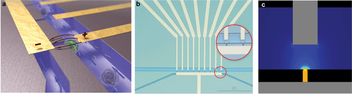 | ||
| Fig. 1 Silicon-glass microfluidic device for single cell electroporation and gene transfection studies (20 × 15 × 1 mm) (a) Artistic 3D impression of trapped cells; (b) Microfluidic chip layout, zoom-in on trapped single cells; (c) Analysis of the electric field strength distribution at the trapping sites shows that a voltage of 1 V yields an electric field strength of 0.57 kV cm–1. | ||
The electrodes are positioned such that individual traps can be electrically addressed. The electric field is focused at the trapping sites (Fig 1c), while it is negligible in the upper channel, as well as in the neighboring trapping sites (as analyzed with finite element modeling). Thus, cells which are not trapped or trapped at the neighboring trapping sites are not affected by the electroporation protocol, as was verified experimentally.
The integrated microholes structure in the flow-through chip represents a way of handling single cells. The cell sample flows along the upper channel, while the lower channel is used to create an under-pressure, which was accomplished by suction (via a pump, 1–2 psi) on the bottom access hole. Once the cells have been trapped, the pump is switched off and cells are localized at the traps.
After trapping of cells, the DNA construct to be electroporated is loaded into the cell trap device. 40 µl of the DNA construct at a concentration of 100 ng ml–1 is added in the top and bottom reservoirs and transported into the microfluidic channels by hydrodynamic flow. DNA–cell contact is established within a pre-incubation period of 10 min before applying an electric field. Subsequently, DNA transport across the cell membrane is initiated by one electric pulse of 6 ms and electric field strength of 0.67 kV cm–1. A post-incubation time up to 10 min is given for the cell–DNA mixture before cell culture medium is added to the microfluidic channels. The chip is then immersed in a small Petri dish with this cell culture medium and placed in the incubator (37 °C and 5% CO2). Optical inspection for gene expression of the cells is done 24 h after electroporation.
Mouse myoblastic cells (C2C12)
C2C12 (ATCC) cells were cultured in DMEM medium (Invitrogen) supplemented with 10% fetal bovine serum (FBS) (Invitrogen), 100 IU ml–1penicillin, 100 mg ml–1streptomycin, 2 mM L-glutamine, 250 mg ml–1 fungizone and 1% sodium pyruvate. Cells were harvested by incubation with 0.025% (w/v) trypsin (Invitrogen).Mesenchymal stem cells (MSCs)
Mesenchymal stem cell growth medium consisted of αMEM (Invitrogen), 10% FBS (Cambrex), 1 ng ml–1bFGF (Invitrogen), 100 µg ml–1penicillin, 100 IU ml–1streptomycin (Invitrogen), and 0.4 mmol ml–1ascorbic acid (Sigma). Cells were harvested by incubation with 0.25% (w/v) trypsin (Invitrogen). Cells were used up to passage number 6 (approximately 40 passage doublings)For electroporation
Cells were harvested using 0.25% trypsin. Trypsin was inactivated by addition of complete growth medium, followed by centrifuging. Cells (C2C12 or MSC) were resuspended in electroporation buffer (10 mM HEPES pH 7.4, 140 mM NaCl, 2.68 mM KCl, and 1.7 mM MgCl2, 25 mM glucose, pH 7.4) at a concentration of 0.5×10⁶cells ml–1.Generation of an EGFP-ERK1 fusion construct
ERK1 DNA was amplified using PCR with Pfu Polymerase (Promega). The PCR primers were directed against the start and stopcodon and included specific restriction sites for easy isolation. The PCR products were cloned into PCR2.1 using a TOPO TA cloning kit (Invitrogen). ERK1 was isolated from PCR2.1 by digestion with XhoI and BamHI and ligated into the XhoI and BamHI sites of pEGFP-N1 (Clontech).Instrumentation
The microfluidic device was mounted onto an X-Y-Z translation stage on an inverted wide fluorescence microscope (Leica DM IRM, Leica Microsystems, Wetzlar, GmbH, Germany). The microscope system is equipped with a mercury lamp, 20×, 40×, 50×, 63× objectives, and a fluorescence filter set (BP 480/40, LP 515). In addition, a computer-controlled CCD camera (Leica DFC300 FX) was mounted on the microscope for image recording. For the electroporation signal, a custom-made Labview (National Instruments) application controls a function generator card (NI5041, National Instruments) and a data acquisition card (NI PCI-6221, National Instruments), which were connected to the electrodes of the device via an especially home-designed holder.Cell imaging and correction for photobleaching
Track images were taken every 5 min with 488 nm excitation and a LP 515 emission filter. Fluorescence intensity changes in either the cytoplasm or nucleus of the cells was determined using ImageJ software.13 For correction of photobleaching, it is assumed that over the time of the experiment, the total fluorescent intensity in the cell is constant. In order to determine the corrected intensity, the mean intensity is calculated inside a mask of the whole cell (I0) and inside a region of interest, defined manually, both in the cytoplasm and in the nucleus of the cell upon their position over time. Subsequently, each pixel in each frame was multiplied by the factor (I0/It), where I0 is the original intensity (t = 0) and It is the current frame intensity. For time zero (t = 0 min) the correction factor is 1, but as the image bleaches, the correction factor gets larger. This correction factor was applied to the track images for the nuclear translocation of EGFP-ERK1, as well as to the graphs of the fluorescence intensity versus time.Electric field distribution
The electric field distribution in the cell trapping device has been modeled using finite element modeling software (Femlab 3.0, Comsol, Sweden) for a 2D situation. The DC conductive medium model was used for a static state situation, which solves Gauss' differential equation. The boundary conditions are considered as being electrically insulated, with the two electrodes being 1 V and grounded. The subdomain has a conductivity of 0.1 S m–1.Results
Electroporation of C2C12 cells
In order to introduce DNA into cells, we determined the electrical parameters for electroporation of mammalian cells. Since human adult stem cells are relatively hard to isolate and cannot be kept in culture indefinitely, we used a C2C12 mouse myoblastic cell line that is similar in size and has some of the properties of the MSC.The voltage (E-field) and pulse length needed for cell membrane permeabilization of individual C2C12 cells that are trapped in the cell trap device were determined by using propidium iodide (PI) as membrane integrity indicator. In a series of experiments, pulses with different amplitudes and/or pulse lengths were applied to individual cells and the fluorescence intensity of the cell was measured one minute after each single pulse. At the start of each experiment, trapped cells were not red fluorescent, indicating that the cell membrane was intact. First the minimum voltage for successful PI uptake was determined for a pulse length of 6 ms. Electrical pulses of 6 ms with increasing amplitude from 1 to 3 V (steps of 0.5 V) and an interval pulse of 1 min were applied to the cells (Fig. 2a–b and supplementary Fig. S1).† Subsequently, for the lowest voltage for electroporation of C2C12 cells (2 V), the effect of the pulse length on PI uptake was studied (supplementary Fig. S2).† In order to test DNA uptake under the defined parameters, a DNA construct encoding green fluorescent protein (EGFP-N1) was electroporated into C2C12 cells. Twenty-four hours after electroporation, EGFP expression was visible in all cells as green fluorescent staining (Fig. 2d and Table 1). The cells also showed healthy morphology observed under light microscopy images. This healthy morphology was maintained at least 120 h post-transfection (after which the cells had divided one time). Thus, a potential of 2 V for at least 6 ms results in single cell electroporation of all C2C12 cells. This electroporation procedure resulted for the first time in GFP transfection and expression into single C2C12 cells and was used to transfect plasmids into MSCs.
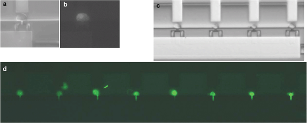 | ||
| Fig. 2 Electroporation and transport PI and expression of EGFP-N1 into C2C12 cells. Proof of principle; (a) bright field and (b) fluorescence image of C2C12 cell showing PI uptake after a pulse of 2 V and 6 ms; (c) immobilised C2C12 cells in the microfluidic device before electroporation; (d) Overview of all nine cell traps in the chip: electroporation of EGFP-N1 in C2C12 cells resulted in 100% transfection efficiency after 24 h, as visible by EGFP expression. | ||
| Cell type | GFP experiments | GFP-ERK experiments | ||||||
|---|---|---|---|---|---|---|---|---|
| # Trapped cells | # Transfected cells (green cells) | TE (%) | # Trapped cells | # Transfected cells (green cells) | TE (%) | |||
| 24 h | Avg | 24 h | Avg | |||||
| C2C12 | 7 | 7 | 100 | 75 | 7 | 7 | 100 | 70 |
| 5 | 3 | 60 | ||||||
| 8 | 3 | 38 | ||||||
| 3 | 1 | 33 | ||||||
| 9 | 7 | 78 | ||||||
| 7 | 6 | 86 | ||||||
| hMSC | 6 | 5 | 80 | 65 | 4 | 4 | 100 | 90 |
| 5 | 5 | 100 | ||||||
| 8 | 8 | 100 | ||||||
| 8 | 6 | 75 | ||||||
| 6 | 3 | 50 | 6 | 4 | 67 | |||
| 5 | 5 | 100 | ||||||
| 8 | 8 | 100 | ||||||
| 4 | 3 | 75 | ||||||
Electroporation of human mesenchymal stem cells
Extracellular signal-regulated kinase, ERK1 or MAPK3, is a protein that is important for transducing signals from the cells' environment to the cell nucleus.14 Its action is important for a variety of cellular functions, from proliferation and development, to inflammatory responses and programmed cell death.15 Binding of growth factors to receptors on the cell membrane results in ERK1 activation and subsequent nuclear translocation, where it can induce gene expression.16 To examine whether cells are still able to respond to their environment after electroporation in a chip, we have utilized an enhanced green fluorescent protein (EGFP)-ERK1 fusion construct. Addition of growth factors to the cells should result in binding of the growth factor to its corresponding receptor, with subsequent activation of the signaling cascade. One of the growth stimulatory factors used in culturing MSC is fibroblast growth factor 2, FGF-2. Addition of FGF-2 should only result in nuclear translocation of our EGFP-ERK1 fusion protein if the cells are healthy and responsive.To investigate the responsiveness to the environment, MSCs were trapped in the device and electroporated with vector DNA encoding either EGFP or EGFP-ERK1. Twenty-four hours after electroporation EGFP or EGFP-ERK1 expression was visible as green fluorescence staining in the cytoplasm, as well as the nucleus. At this time, the normal growth medium was exchanged for medium without FGF-2 and containing 1% serum and the cells were left to grow for an additional 24 h. This serum starvation results in inhibition/lack of activation of surface receptors and subsequent cytoplasmic localization of EGFP-ERK1 (Fig. 3), while EGFP remains homogeneously distributed. Forty-eight hours after electroporation, cells were stimulated by addition of 10 ng ml–1 FGF-2 and cells were imaged every 5 min to visualize protein localization.
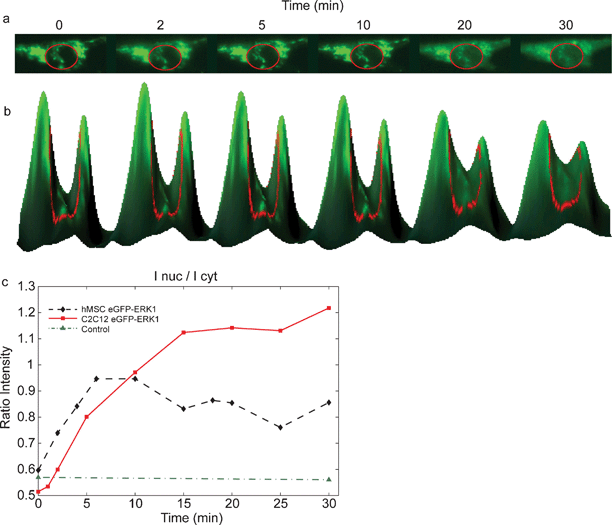 | ||
| Fig. 3 Nuclear translocation of EGFP-ERK1 in MSCs after growth factor stimulation. (a) Addition of FGF-2 to cells expressing EGFP-ERK1 results in the nuclear translocation, visible as increased green fluorescence in the nucleus after stimulation (inside red circle); (b) 3D-visualisation of the translocation; curve height corresponds to fluorescence intensity; (c) time courses for EGFP (control (▲)) and EGFP-ERK1 translocation following growth factor stimulation at t = 0 min: fluorescence intensity of the nucleus measured in time after FGF-2 addition for C2C12 (■) and MSC (♦) cells. | ||
As shown in Fig. 3, EGFP-ERK1 was localized mainly in the cytoplasm after serum starvation and translocated to the nucleus upon FGF-2 stimulation, which is visible as increased green fluorescence in the nucleus in time (Fig 3a). Fig 3b shows the fluorescence intensities of the cytoplasm and nucleus (inside red circle) for various times in a 3D-representation: the peaks correspond to the cytoplasm, the valley between the peaks to the nucleus. That EGFP-ERK1 translocates from the cytoplasm into the nucleus (after FGF-2 stimulation) can be seen in Fig. 3b as a decrease in peak-heights accompanied by an increase of the valley-height (in time). The ratio of the intensities of the nucleus and cytoplasm is plotted in Fig. 3c The maximum intensity of EGFP-ERK1 in the nucleus was reached in less than 15 min after addition of FGF-2, which corresponds with nuclear translocation in response to activation of extracellular signaling in a wide variety of cell types.14 Control experiments showed that EGFP localization was not dependent on either serum starvation or FGF-2 stimulation, indicating that ERK1 and not EGFP responded to FGF-2 stimulation (Fig. 3c). According to us, for the first time, a microfluidic device was used for expression and subsequent nuclear translocation of GFP-ERK1 constructs in human MSCs.
Single cell experimentation
Addition of FGF-2 to the growth medium increases the life-span of MSCs from 40 passage doublings (PDs) to 70 PDs and maintains the differentiation potential until 50 PDs,17 indicating a role of FGF-2 in the maintenance of multipotency and proliferation potential. However, the mechanisms by which FGF-2 exerts its function are as yet unknown.FGF-2 binding to its receptor (FGFR) on the cell surface is followed by activation of the mitogen-activated-protein kinases (MAPK) signaling pathway and nuclear localization of ERK1/ERK2. In addition, FGF-2 has been shown to be important for proliferation of many cell types by localizing to the nucleus,18,19 which results in activation of many nuclear proteins. This is a result of a direct interaction of FGF-2 with casein kinase 2 (CK2), which stimulates CK2 activity.20 Our results show that addition of FGF-2 to the cells results in ERK1 nuclear localization, indicating the activation of the MAPK pathway by activation of the FGFR. In addition, we observed that transport of ERK1 in response to FGF-2 stimulation likely involves actin filament-like structures (Fig. 4). The dot-like structures resulting from EGFP-ERK1 that appear after FGF-2 stimulation seem to be localized along threads that could facilitate transport into the cell nucleus. Although the observed kinetics of the shift of cytoplasmic versus nuclear fluorescence is compatible with nuclear ERK1 activity of growth factor stimulation, further experiments are required the substantiate these findings.
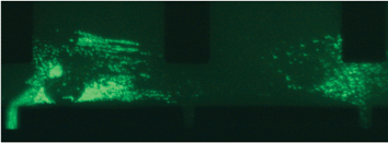 | ||
| Fig. 4 EGFP-ERK1 localized along internal structures in the cytoplasm. Before addition of FGF-2, EGFP-ERK1 is visible as green structures along what appear to be internal filaments. | ||
Discussion and conclusions
To the best of our knowledge, this report is the first to show that we can transfect single human mesenchymal stem cells with high efficiency, while maintaining the viability and the ability of the cell to respond to changes/factors in its environment. These experiments show that we can use these microfluidic devices to introduce DNA into stem cells at very high efficiency via single cell electroporation while imaging them individually. This high efficiency can be obtained through precise control of electroporation potential for each individual cell, as opposed to bulk methods where the electroporation potential varies for each individual cell. Since human MSCs are a rare cell population with a limited life-span, it is important that genetic modification is carried out efficiently. The presented results will provide essential knowledge for a second generation chip that, through parallelization, will enable gene transfer in larger numbers of cells, while maintaining the same high efficiency. In addition, we have shown that we can manipulate single cells in microfluidic devices by presenting growth factors to its microenvironment and imaging internal protein dynamics with relatively high resolution.Since the experimental conditions for manipulation of cells in chips can be tightly controlled while maintaining normal physiological responses, this study shows that cells in microfluidic devices offer prospects to study dynamic processes at the single cell level
Acknowledgements
We thank I. van Uitert for her help regarding Labview programming and 3D images and P. Lenormand for providing us ERK1 in pcDNA3 as a kind gift. This work was supported by the Dutch Technology Foundation STW (Simon Stevin Master grant), the applied science division of NWO and the NanoNed program of the Ministry of Economic Affairs of The Netherlands. This work has been carried out with the Flagship Nanofluidics in the NanoNed program. In the Netherlands, the 3 universities of technology have formed the 3TU.Federation. This article is a result of research in the 3TU.Centre for Bio-Nanoapplications.References
- H. Andersson and A. van den Berg, Sens. Actuators, B, 2003, 92, 315–325 CrossRef.
- A. Valero, F. Merino, F. Wolbers, R. Luttge, I. Vermes, H. Andersson and A. van den Berg, Lab Chip, 2005, 5, 49–55 RSC.
- Y. Huang and B. Rubinsky, Sens. Actuators, A, 2003, 104, 205–212 CrossRef.
- M. Khine, A. Lau, C. Ionescu-Zanetti, J. Seo and L. P. Lee, Lab Chip, 2005, 5, 38–43 RSC.
- J. Olofsson, M. Levin, A. Stromberg, S. G. Weber, F. Ryttsen and O. Orwar, Anal. Chem., 2007, 79, 4410–4418 CrossRef CAS.
- M. B. Fox, D. C. Esveld, A. Valero, R. Luttge, H. C. Mastwijk, P. V. Bartels, A. van den Berg and R. M. Boom, Anal. Bioanal. Chem., 2006, 385, 474–485 CrossRef CAS.
- H. A. Awad, D. L. Butler, G. P. Boivin, F. N. Smith, P. Malaviya, B. Huibregtse and A. I. Caplan, Tissue Eng., 1999, 5, 267–277 CrossRef CAS.
- M. Owen and A. J. Friedenstein, Ciba Found. Symp., 1988, 136, 42–60 Search PubMed.
- M. F. Pittenger, A. M. Mackay, S. C. Beck, R. K. Jaiswal, R. Douglas, J. D. Mosca, M. A. Moorman, D. W. Simonetti, S. Craig and D. R. Marshak, Science, 1999, 284, 143–147 CrossRef CAS.
- U. Lakshmipathy, B. Pelacho, K. Sudo, J. L. Linehan, E. Coucouvanis, D. S. Kaufman and C. M. Verfaillie, Stem Cells, 2004, 22, 531–543 Search PubMed.
- R. Ando, H. Mizuno and A. Miyawaki, Science, 2004, 306, 1370–1373 CrossRef CAS.
- M. Costa, M. Marchi, F. Cardarelli, A. Roy, F. Beltram, L. Maffei and G. M. Ratto, J. Cell Sci., 2006, 119, 4952–4963 CrossRef CAS.
- W. Rasband, 2004, ImageJ imaging software.
- M. J. Robinson and M. H. Cobb, Curr. Opin. Cell Biol., 1997, 9, 180–186 CrossRef CAS.
- A. V. Khokhlatchev, B. Canagarajah, J. Wilsbacher, M. Robinson, M. Atkinson, E. Goldsmith and M. H. Cobb, Cell, 1998, 93, 605–615 CrossRef CAS.
- A. Brunet, D. Roux, P. Lenormand, S. Dowd, S. Keyse and J. Pouyssegur, EMBO J., 1999, 18, 664–674 CrossRef CAS.
- G. Bianchi, A. Banfi, M. Mastrogiacomo, R. Notaro, L. Luzzatto, R. Cancedda and R. Quarto, Exp. Cell Res., 2003, 287, 98–105 CrossRef CAS.
- G. Bouche, N. Gas, H. Prats, V. Baldin, J. P. Tauber, J. Teissie and F. Amalric, Proc. Natl. Acad. Sci. U. S. A., 1987, 84, 6770–6774 CrossRef CAS.
- X. Zhan, X. Hu, S. Friedman and T. Maciag, Biochem. Biophys. Res. Commun., 1992, 188, 982–991 CrossRef CAS.
- K. Bailly, F. Soulet, D. Leroy, F. Amalric and G. Bouche, FASEB J., 2000, 14, 333–344 CAS.
Footnotes |
| † Electronic supplementary information (ESI) available: Supplementary Fig. S1 and Fig. S2 and movie clip. See DOI: 10.1039/b713420g |
| ‡ These authors contributed equally. |
| This journal is © The Royal Society of Chemistry 2008 |