 Open Access Article
Creative Commons Attribution 3.0 Unported Licence
Efficient direct seawater electrolysers using selective alkaline NiFe-LDH as OER catalyst in asymmetric electrolyte feeds†
Sören
Dresp‡
 ,
Trung
Ngo Thanh‡
,
Malte
Klingenhof
,
Sven
Brückner
,
Philipp
Hauke
and
Peter
Strasser
,
Trung
Ngo Thanh‡
,
Malte
Klingenhof
,
Sven
Brückner
,
Philipp
Hauke
and
Peter
Strasser
 *
*
Department of Chemistry, Technical University Berlin, Straße des 17. Juni 124, 10623 Berlin, Germany. E-mail: pstrasser@tu-berlin.de
First published on 20th May 2020
Abstract
Direct seawater electrolysis faces fundamental catalytic and process engineering challenges. Here we demonstrate a promising seawater electrolyser configuration using asymmetric electrolyte feeds. We further investigated the faradaic O2 efficiency of NiFe-LDH in alkalinized Cl−-containing electrolytes in comparison to commercial IrOx-based catalysts. Other than IrOx, NiFe-LDH prevents the oxidation of Cl− and appears highly selective for the oxygen evolution reaction in alkalinized seawater even at cell potentials beyond 3.0 Vcell.
The storage of renewable solar or wind electricity is a major challenge in our efforts to build a sustainable future energy system. More and more focus is placed on water electrolysers that split water into O2 and H2 (2H2O + energy → 2H2 + O2) with H2 being the energy storage/platform molecule of interest. Water electrolysers operate on highly purified water, which is incompatible with wind parks at offshore ocean locations or photovoltaic plants in ocean-side arid deserts. There, the direct use of seawater in water electrolysers would be highly desirable.1 But splitting seawater faces chemical and engineering challenges. The competing reactions between the desired oxygen evolution reaction (OER) (4OH− → O2 + 2H2O + 4e−; E0 = 1.23 VRHE) and the undesired chloride oxidation reactions, i.e. the Chlorine evolution reaction (ClER) (2Cl− → Cl2; E0 = 1.36 VRHE) at low pH and the formation of hypochlorite (OCl−) (Cl− + 2OH− → OCl− + H2O + 2e−; E0 = 1.71 VRHE) at high pH restrict the operating electrolyser cell voltage.2 The two design criteria for seawater splitting mandate an anode potential <1.72 VRHE and an electrolyte pH > 7.5 to prevent ClO− formation to ensure a 100% selective OER.2 Despite the favourable natural pH of seawater (pHseawater ∼ 8),3,4 alkaline pH buffering is needed to avoid local pH changes at the anode surface.5 Indeed, at high pH, NiFeOxHy layered double hydroxide (NiFe-LDH) has revealed its full performance as anode catalyst for seawater electrolysers.6 However, at high pH, the cathode faces Mg(OH)2 deposition blocking catalytic active sites for the hydrogen evolution reaction (HER).7 In addition, the separator/membrane strongly affects the overall electrolyser performance:8 saline water constituents such as Cl− reduce the ionic conductivity of the anion exchange membrane (AEM) by ion exchange and can result in performance losses. Efficient seawater splitting without making it more alkaline has therefore remained a challenge. Typical seawater electrolyser use a symmetric feed of alkalinized seawater to achieve efficiencies comparable to state of the art electrolysers.7
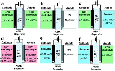
Here, we report how asymmetric electrolyte feeds increase the performance of seawater electrolysers and avoid the undesired alkalinisation of seawater. We demonstrate our approach in an electrolyser operating directly on natural seawater. Previous designs of seawater electrolysers included identical electrolyte compositions (alkalinized seawater) on anode and cathode,6,8–10 but the limiting anode potential of 1.72 VRHE to ensure 100% oxygen selectivity resulted in low electrolyser cell current densities limited to about 200 mA cm−2. More efficient and compact electrolysers should reach cell performances and current densities of at least up to 1 A cm−2. To circumvent the limiting potential range, we developed a new electrolyser feed scheme and compared it to conventional electrolyte feed schemes of seawater and alkaline electrolysers. Fig. 1 shows the various feed schemes discussed here in more detail. While Fig. 1a and d show conventional symmetric electrolyte feeds, Fig. 1b and e illustrate – in analogy but opposite to PEM electrolysers – the electrolyte feed at the cathode only. Fig. 1c and f demonstrate our novel approach for efficient future seawater electrolysers using asymmetric feed scheme compositions.
The electrolyser studies were performed using a customized test station (Fig. S1, ESI†), commercial cell assemblies (Fig. S2, ESI†) and membrane electrode assemblies (MEAs) including an anion exchange membrane (AEM) spray coated with crystalline Ni0.66Fe0.34-LDH (Fig. S3, ESI†) as anode catalyst material and commercially available cathode catalyst. Compared to other 3d-transition metal catalysts, NiFe-LDH has shown outstanding OER activity and could proof its suitability as seawater oxidizing catalyst.2,6,8,11,12 The microwave-assisted solvothermal synthesis and properties of NiFe-LDH are described in the ESI† and elsewhere.8 All configurations were initially tested using a specific measurement protocol (Fig. S4, ESI†), consisting of subsequent polarization curves and potentiostatic tests with 1.5 h and 12 h at 1.7 Vcell.
Initial performance test
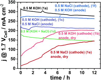
Fig. 2 shows a 12 h potentiostatic test at 1.7 Vcell. Consistent to prior results,8 the symmetric 0.5 M KOH electrolyte feed, that is the conventional alkaline electrolysis on highly purified water, showed the best performance. Alkaline seawater feed on either side (Fig. 1d) showed very low performance.8 Surprisingly, the asymmetric feed schemes with distinct fed compositions on cathode and anode (Fig. 1c and f) showed superior cell performances compared to the symmetric mixed electrolytes (Fig. 1d). | ||
| Fig. 2 12 h electrolyser stability measurement at constant cell potential of 1.7 Vcell of various electrolyte feeds using an active area of 5 cm2 and commercial Pt/C (48.5 wt%) with loading of 0.5 mgPt cm−2 as cathode and crystalline Ni0.66Fe0.34-LDH with loading of 2.0 mgcat cm−2 as anode catalyst. The feed schemes of Fig. 1 are indicated in parentheses behind the electrolyte composition. | ||
Even the saline seawater feed at the cathode only (Fig. 1e), outperformed the mixed electrolyte feed scheme of Fig. 1d significantly.
While initial electrolyser polarization curves differed sharply among the schemes, the cell characteristics after 12 h converged somewhat (see Fig. S5, ESI†) in line with the 12 h stability measurement in Fig. 2. It appears as if the membrane needs a longer break-in time for dry anodes, which is further supported by the trends in the high frequency resistances (HFR) of Fig. S6 (ESI†), in which the HFR decreases after each long-term test.
However, the intriguing possibility of using only untreated seawater directly (Fig. 1e) caused us to extend the stability test beyond 12 h (Fig. S7a, ESI†). The current density gradually increased, until after 18 h the cell performance dropped to almost zero current. The performance loss was attributed to strong corrosion processes at the catalyst and the porous transport layer (PTL): a dark green NiOx solution accumulated in the anode reservoir (Fig. S7c, ESI†), while the PTL sharply darkened (Fig. S7d, ESI†). Without a buffer or an alkaline electrolyte, the local pH has likely decreased drastically such that the anode materials suffered strong acidic dissolution. This led us to the conclusion that the anodic feed of KOH is critical. Hence, a continuously circulating KOH anolyte combined with pure single-pass seawater feeding at the cathode appeared as the desired scheme (Fig. 1f). For this asymmetric electrolyte feed scheme, we analysed the electrocatalysis and transport of Cl− ions across the membrane and detected a total Cl− amount of 6.36 ± 0.04 mmol after our standardized testing protocol (Fig. S3, ESI†). As shown below, this low level of Cl− cross over into the circulating KOH anolyte does not affect the anode catalysis thanks to the high catalytic selectivity of NiFe-LDH for the OER.
Seawater electrolysis selectivity
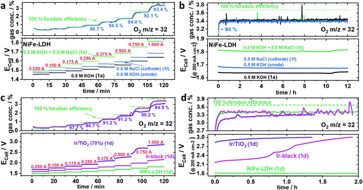
A chemically selective anode catalyst is important for durable seawater electrolysers in order to prevent component degradation caused by the oxidation of Cl− to wet Cl2 (acidic) or to hypochlorite (OCl−) (neutral/alkaline). Faradaic efficiencies of O2 were obtained from inline mass spectrometry (MS) conducted during a galvanostatic test protocol (Fig. S8, ESI†). To detect hypochlorite (OCl−), we used an iodometric titration method.Fig. 3a shows the sequence of chronopotentiometric (CP), applied current steps that made up a full polarization curve (0.05–1.0 A, steps labelled in red). Due to residual O2 from the preceding break-in CP step at 0.2 A, faradaic efficiencies of O2 (FEO2) below 0.25 A exceed their theoretical value. Even though the measured potential varied for the different electrolytes, all their FEO2 remained almost identical and close to 100%, indicating no significant Cl− oxidation at any time. Compared to the symmetric mixed NaCl/KOH feed scheme of Fig. 1d, the cell potential using asymmetric, separated KOH and saline feeds (Fig. 1f) displayed significantly lower, and thus favourable cell voltages resulting in a superior cell performance. Interestingly, all electrolyte feed schemes showed stable activities over the 12 h (Fig. 3b). Even at cell voltages >1.8 Vcell (Fig. 3b green) the FEO2 stayed at 94%, suggesting the absence of significant Cl− oxidation. Iodometric titration confirmed that no OCl− was formed at any time. In order to convince ourselves that OCl− formation is possible and detectable, however, we tested Ir/TiO2 and Ir-black as shown in Fig. 3c and d.
 | ||
| Fig. 3 Faradaic efficiency of O2 (FEO2) using various anode catalysts with an active area of 5 cm−2 and a loading of 2.0 mgcat. cm−2. O2 was analysed by mass spectrometry under 100 ml min−1 N2 carrier gas flow. The feed schemes of Fig. 1 are indicated in parentheses, the applied currents are in red numbers, the green dotted line represents an O2 concentration corresponding to 100% FEO2. (a and b) Ni0.66Fe0.34-LDH as anode catalyst using the following electrolyte feed schemes: symmetric 0.5 M KOH (black), symmetric 0.5 M (KOH + NaCl) (green) and asymmetric 0.5 M KOH at the anode and 0.5 M NaCl at the cathode. (a) Stepped constant current tests with current holds of 15 min each (b) subsequent 12 h stability test at applied current density of 200 mA cm−2 (I = 1.0 A). (c and d) Commercial Ir-black (magenta) and TiO2 supported Ir (purple) anode benchmark catalysts versus NiFe-LDH (green) using symmetric 0.5 M (KOH + NaCl) electrolyte feed scheme. (c) Stepped constant current tests with current holds of 15 min each (d) subsequent stability test at 200 mA cm−2 (I = 1.0 A). | ||
While iridium black (magenta) showed an undesired larger cell voltage, the FEO2 was identical to NiFe-LDH (green). In contrast, Ir/TiO2 (purple) showed a sudden drop in FEO2 at Ecell >2.4 Vcell pointing to the electro-catalytic formation of OCl−. Thus, 2.4 V appears to be the onset potential of OCl− formation. Looking at the CP at 1.0 A (200 mA cm−2) in Fig. 3d, Ir-black showed a dramatic increase of Ecell surpassing 2.4 V (Fig. 3d) resulting in a drop of O2 concentration and thus in FEO2. Iodometry after both Ir-black and Ir/TiO2 confirmed the formation of OCl−. In case of the Ir/TiO2 400 μmol and Ir/black 320 μmol OCl− could be determined.
Despite the change in FEO2 for Ecell > 2.4 Vcell, it remained unclear whether OCl− was formed over a short time window or whether it formed gradually over the entire testing period. It appears kinetically interesting that the two electron transfer reaction to OCl− in alkaline requires such a large overpotential, while the formation of Cl2 showed comparably small overpotential in acidic environment as presented by Vos et al.13 Conclusively, Ir-based catalysts in our tests showed inferior performances as seawater anode catalysts compared to NiFe-LDH. To investigate the OER/ClOx selectivity of NiFe-LDH under higher loads, larger cell potentials appear necessary to enter a regime where the OCl− formation is kinetically preferred.
In that context, the absolute current while using NiFe-LDH as anode catalyst was increased up to 4.0 A (800 mA cm−2) resulting in cell potentials larger than 2.4 V (Fig. S10, ESI†). All faradaic efficiencies ranged around 94%, which is consistent with our former tests. Finally, at 4.0 A, the potential suddenly increased to 4.0 V showing reduced FEO2 of 84%. But again, no OCl− was detected by iodometry. This led us to believe that the lower FEO2 was caused by the shorter retention time. In essence, NiFe-LDH appeared to successfully suppress Cl− oxidation even at large currents, which highlights it favourable catalytic OER selectivity and suitability for seawater electrolysis. The excellent OER selectivity of NiFe-LDH at very high voltages and currents underlines that the previously reported Design Criteria of seawater electrolysis are of thermodynamic, but not kinetic nature. In fact, high current densities at cell voltages of up to 2.5 Vcell in Cl−-containing electrolyte is feasible. This also supports the suitability of NiFe-LDH electrodes as investigated by Kuang et al.6 and underscores the potential of our proposed asymmetric KOH/NaCl feed configuration.
Long-term stability
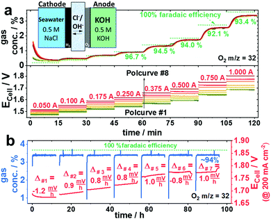
To investigate the stability of the NiFe-LDH gas diffusion electrode deployed in seawater electrolysers with asymmetric electrolyte feed, we extended the initial selectivity test by six additional repetitive cycles between the galvanostatic polarization curve and the 12 h galvanostatic test (protocol see Fig. S4, ESI†) to obtain a total test time of ∼100 h consisting of eight polarization curves and seven 12 h tests at 200 mA cm−2 (Fig. 4). Although the measured electrode potential slightly increased for each cycle, the FEO2 values remained essentially identical. This applies for all polcurves (Fig. 4a) and at any time during each of the seven 12 h stability tests (Fig. 4b). Starting from 1.7 Vcell at 200 mA cm−2, the cell voltage increased by roughly 8–10 mV per 12 h stability cycle, resulting in ∼100 mV after the entire 100 h test. Given the stability of NiFe-LDH electrodes,6 we attribute this electrolyser performance loss to anode catalyst, current collectors or membrane components. Indeed, AEM membranes have remained one of the bottlenecks of durable seawater electrolysers. Further, Pt-free seawater cathode HER catalysts will become important in the future, because Pt is particularly vulnerable in Cl− containing electrolytes due to the formation of Cl-complexes. Mn-doped NiO/Ni hetero-structured cathodes exhibiting Pt-like performances in both neutral electrolytes and natural seawater14 or CoMoP@C electrocatalysts with even superior activities to Pt/C are currently under investigations and will be incorporated in the current flow schemes in the future.15Conclusions
We have developed and reported a new asymmetric electrolyte feed concept for direct seawater electrolyser. This approach enables direct feed of neutral seawater at the cathode in a single pass, while circulating pure KOH electrolyte at the anode. In Cl− containing alkaline electrolyte, NiFe-LDH showed superior catalytic activity and OER selectivity compared to Ir-based benchmark catalysts up to unprecedented cell voltages of up to 4.0 Vcell. Even though trace amounts of Cl− crossed the membrane to the anode compartment, the NiFe-LDH anode catalyst remained fully selective for OER without any oxidation of Cl−, which makes it an excellent catalyst for continuous, high-power direct seawater electrolysis at high cell voltages and high current densities. The catalytic mechanism behind the ClER suppression by using NiFe-LDH remain unclear and require further investigations in a future work.Conflicts of interest
There are no conflicts to declare.Acknowledgements
Financial support by the federal ministry for economic affairs and energy (Bundesministerium für Wirtschaft und Energie, BMWi) under grant number 03EIV041F in the collaborative research project “MethQuest” in the group “MethFuel” and the German Research Foundation (DFG) through grant reference number STR 596/12-1 are grateful acknowledged.Notes and references
- S. Dresp, F. Dionigi, M. Klingenhof and P. Strasser, ACS Energy Lett., 2019, 4, 933–942 CrossRef CAS
.
- F. Dionigi, T. Reier, Z. Pawolek, M. Gliech and P. Strasser, ChemSusChem, 2016, 9, 962–972 CrossRef CAS PubMed
.
- R. Kester Dana, W. Duedall Iver, N. Connors Donald and M. Pytkowicz Ricardo, Limnol. Oceanogr., 1967, 12, 176–179 CrossRef
.
- S. M. Ji, H. Jun, J. S. Jang, H. C. Son, P. H. Borse and J. S. Lee, J. Photochem. Photobiol., A, 2007, 189, 141–144 CrossRef CAS
.
- Y. Surendranath, M. Dinca and D. G. Nocera, J. Am. Chem. Soc., 2009, 131, 2615–2620 CrossRef CAS PubMed
.
- Y. Kuang, M. J. Kenney, Y. Meng, W.-H. Hung, Y. Liu, J. E. Huang, R. Prasanna, P. Li, Y. Li, L. Wang, M.-C. Lin, M. D. McGehee, X. Sun and H. Dai, Proc. Natl. Acad. Sci. U. S. A., 2019, 116, 6624–6629 CrossRef CAS PubMed
.
- W. Tong, M. Forster, F. Dionigi, S. Dresp, R. Sadeghi Erami, P. Strasser, A. J. Cowan and P. Farràs, Nat. Energy, 2020, 6, 367–377, DOI:10.1038/s41560-020-0550-8
.
- S. Dresp, F. Dionigi, S. Loos, J. Ferreira de Araujo, C. Spöri, M. Gliech, H. Dau and P. Strasser, Adv. Energy Mater., 2018, 8, 1800338 CrossRef
.
- G. Amikam, P. Nativ and Y. Gendel, Int. J. Hydrogen Energy, 2018, 43, 6504–6514 CrossRef CAS
.
- S. H. Hsu, J. Miao, L. Zhang, J. Gao, H. Wang, H. Tao, S. F. Hung, A. Vasileff, S. Z. Qiao and B. Liu, Adv. Mater., 2018, 30, 1707261 CrossRef PubMed
.
- S. Dresp and P. Strasser, ChemCatChem, 2018, 10, 4162 CrossRef CAS
.
- F. Dionigi and P. Strasser, Adv. Energy Mater., 2016, 6, 1600621 CrossRef
.
- J. G. Vos and M. T. M. Koper, J. Electroanal. Chem., 2018, 819, 260–268 CrossRef CAS
.
- X. Lu, J. Pan, E. Lovell, T. H. Tan, Y. H. Ng and R. Amal, Energy Environ. Sci., 2018, 11, 1898–1910 RSC
.
- Y.-Y. Ma, C.-X. Wu, X.-J. Feng, H.-Q. Tan, L.-K. Yan, Y. Liu, Z.-H. Kang, E.-B. Wang and Y.-G. Li, Energy Environ. Sci., 2017, 10, 788–798 RSC
.
Footnotes |
| † Electronic supplementary information (ESI) available. See DOI: 10.1039/d0ee01125h |
| ‡ S. D. and T. N. T. contributed equally. |
| This journal is © The Royal Society of Chemistry 2020 |


