DOI:
10.1039/C9RA06549K
(Paper)
RSC Adv., 2019,
9, 32441-32447
Experimental and computational studies of a graphene oxide barrier layer covalently functionalized with amino acids on Mg AZ13 alloy in salt medium
Received
20th August 2019
, Accepted 2nd October 2019
First published on 11th October 2019
Abstract
Magnesium alloys are promising materials for the biomedical and automobile industries. The Mg alloy's light-weight property leads to numerous industrial applications. However, the magnesium alloy oxide layers are not stable in salt environments. Organic inhibitors and epoxy coatings fail as long term barriers in such media. Recently, carbon based functionalized materials, graphene oxides, were shown to be promising materials for improving corrosion resistance in acid and salt environments. Our research considered graphene oxide covalently functionalized with the amino acid leucine to form anticorrosion coating materials. The functionalized materials were characterized by XRD, Raman, FESEM, HRTEM, FTIR, and AFM methods. The corrosion inhibition efficiency was monitored by electrochemical methods. The novelty of the functionalized graphene oxide materials is that they are water impermeable, and thus could enhance the anticorrosion resistance in salt environments.
1. Introduction
Magnesium-based alloys are light-weight materials which are used broadly in the motor industry. The magnesium alloys have weak corrosion resistance in salt environments. The synthetic organic inhibitor molecules or inorganic metal complex inhibitors are known to fail to have long time inhibition efficiency in corrosive environments. Also, these synthetic inhibitors are harmful to the environment as well as to human life. Furthermore, Birbilis et al. showed that La and LaPO4 coated magnesium alloy AZ91D has corrosion resistance in a 1 M NaCl environment. They suggested that pitting corrosion of the La coated magnesium alloy initiated on alloy surface as compared to LaPO4 coated magnesium alloy. But in the case of LaPO4 coated magnesium alloy no pitting corrosion on the alloy developed due to strong phosphate anchoring on alloy surface.1 Wen et al. studied triethanolamine as corrosion inhibitor in salt environment on magnesium alloy AZ91D. The corrosion inhibition studies revealed that triethanolamine behaves as mixed type corrosion inhibitor in salt environment.2 Xi et al. studied corrosion resistance of phenylalanine polyester amide coated magnesium alloy in artificial human body fluids environments in vitro. The polymer coated magnesium alloy showed outstanding corrosion resistance in vitro.3 The addition of neodymium and zinc to magnesium alloy improved corrosion resistance in vitro and in vivo.4 Liu et al. reported remarkable corrosion inhibition of plasma method hydroxyapatite coated AZ91D magnesium alloys in the human osteoblast cell environment.5 The authors reported corrosion resistance of the laser treated magnesium WE43 alloy in 3.5% NaCl environments. Results suggested that laser treated magnesium alloy had excellent corrosion resistance in salt environments.6 Xu et al. reported corrosion resistance of the phosphate coated AZ13 magnesium alloy in artificial human body fluid. The phosphate coated magnesium alloy showed excellent corrosion resistance due to the phosphate strong physisorption on alloy surface.7 The authors reported that silane modified coated AZ31 magnesium alloy corrosion resistance increased in artificial body fluids due to the silane acting as self-healing agent. Further, alanine, glycine, and leucine amino acids were shown to work as corrosion inhibitors on mild steel in the 1 M HCl medium,8–12 and with increased amount of the inhibitor corrosion inhibition efficiency increased. Furthermore, the cerium decorated GO and GO coated Mg alloy were treated in 3.5% NaCl medium.13–15 It was suggested that with the increase of coating thickness the inhibition efficiency increased for functionalized graphene oxide materials adsorbed on active Mg alloy surface. The amino acids are eco-friendly and demonstrate high electron transfer rates. Leucine functionalized graphene oxide coated Mg AZ13 alloy has not been studied in the salt environment so far. We have performed first investigation of the green corrosion inhibition barrier layer in salt environment.
2. Experimental
2.1. Reactants
Natural graphite, H2SO4, H2PO4, H2O2, KMnO4, and leucine amino acid were purchased from Alfa Aser. Mg AZ31 was of commercial grade, and the GO was synthesized by modified hummer methods. The 1 g of graphite powder was placed into the round bottom flask (RB). The RB was kept in ice containing beaker and 40 ml of H2SO4, 60 ml of H2PO4 and 3 g KMnO4 were slowly added to the mixture. The mixture was refluxed at 60 °C for 12 h and after that the mixture was cooled at room temperature. The final product was washed with excess of deionised water to neutralize the mixture. The black product was dried at 80 °C in vacuum oven.
2.2. Amino acid functionalization
100 mg of GO were placed in the 50 ml of ethanol contained in the 100 ml RB. The mixture was continuously sonicated for 3 h to obtain finely dispersed solution by using Multi Ultrasonic cleaner model SB-300 DTY at 40 W, and 10 mg of leucine were added to the finely dispersed GO solution. This mixture was refluxed at 60 °C continuously for 24 h. The mixture was cooled at room temperature and washed with ethanol and water to obtain neutral solution. The final product was dried at 60 °C in the vacuum oven for 24 h.
2.3. Material characterization
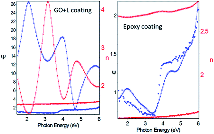
The GO and leucine and graphene oxide (GO + L) functional groups were analysed by using PerkinElmer 65 FTIR. The carbon disorder was studied by confocal Raman WITec 532 nm laser vibration and crystallinity of GO and (GO + L) functional materials was studied by XRD 8 Advance Bruker. Further, the microstructure was studied by using FESEM Merline Carlzeiss, and TEM FEI Model Tecnai G2 S Twin (200 kV) facility GATAN. The coated Mg alloy surface wettability was studied by Drop Shape Analyzer – DSA25. The epoxy and GO + L coated magnesium alloys were dried at 80° for 24 h, after that their thickness was studied at applied voltage ranging from 1.5000 eV to 6.0000 eV, with the increment of 0.0500 eV by Ellipsometer uvisel-2 model. The coating fitting was analysed by UVisel-2 software.
2.4. Corrosion inhibition studies
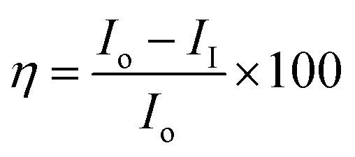
AZ13 mg alloy was cut into 1 cm × 1 cm pieces and polished with series of silicon paper from 400 to 1200 micron.9 The polished Mg alloys were washed with acetone and water before coating. The (GO + L) and epoxy powder were mixed in 2![[thin space (1/6-em)]](https://www.rsc.org/images/entities/char_2009.gif) :1 ratio with binder (polyamine), the coating was done by brush method and brush size was 0.2 micron. After coating Mg alloy was dried for 24 h at 80 °C. As prepared Mg alloy was used as a working electrode, platinum foil was used as counter electrode and Ag/AgCl as a reference electrode for electrochemical reaction. The corrosion inhibition study was carried out in the 3.5% NaCl medium because electrolyte was used at the same concentration. The coated alloys were immersed for 48 h continuously in 3.5% NaCl medium. After this the corrosion inhibition efficiency was analysed by CHI920D model. Corrosion inhibition efficiency was calculated following eqn (1) and (2).
:1 ratio with binder (polyamine), the coating was done by brush method and brush size was 0.2 micron. After coating Mg alloy was dried for 24 h at 80 °C. As prepared Mg alloy was used as a working electrode, platinum foil was used as counter electrode and Ag/AgCl as a reference electrode for electrochemical reaction. The corrosion inhibition study was carried out in the 3.5% NaCl medium because electrolyte was used at the same concentration. The coated alloys were immersed for 48 h continuously in 3.5% NaCl medium. After this the corrosion inhibition efficiency was analysed by CHI920D model. Corrosion inhibition efficiency was calculated following eqn (1) and (2).| |  | (1) |
| |  | (2) |
2.5. Computational studies
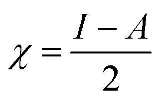
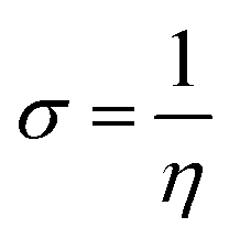
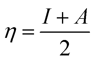
In our calculations we used the C44H16O8 GO model with two –CO2H groups, two –OH group, and two ![[double bond, length as m-dash]](https://www.rsc.org/images/entities/char_e001.gif) O groups. To this model the leucine amino acid molecule was covalently bound through its –NH2 group to the O group located in the centre of the GO model, thus the N group was formed. All calculations were done using the Gaussian09 program package,16 implementing the hybrid B3LYP functional17 and split-valence polarized basis set 6-31G*18 with polarization functions on heavier atoms. The calculations were performed in the gas phase. The electronic structure of the optimized GO–leucine species was calculated and using the molecular orbital energies such global reactivity parameters as electrophilicity, hardness, softness, and electronegativity were calculated by using eqn (3)–(6). Charge distribution analysis was performed using the Natural Bonding Order scheme.19 The structure and molecular orbitals of the model studies were visualised using the Molden software.20
O groups. To this model the leucine amino acid molecule was covalently bound through its –NH2 group to the O group located in the centre of the GO model, thus the N group was formed. All calculations were done using the Gaussian09 program package,16 implementing the hybrid B3LYP functional17 and split-valence polarized basis set 6-31G*18 with polarization functions on heavier atoms. The calculations were performed in the gas phase. The electronic structure of the optimized GO–leucine species was calculated and using the molecular orbital energies such global reactivity parameters as electrophilicity, hardness, softness, and electronegativity were calculated by using eqn (3)–(6). Charge distribution analysis was performed using the Natural Bonding Order scheme.19 The structure and molecular orbitals of the model studies were visualised using the Molden software.20| |  | (3) |
| |  | (4) |
| |  | (5) |
| |  | (6) |
3. Result and discussion
3.1. Spectroscopy
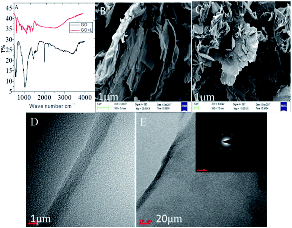
In Fig. 1A (FTIR) the functional groups analysis of GO and (GO + L) composite materials is provided. For the functionalized graphene oxide stretching frequencies are present in Fig. 1A. The GO hydroxyl stretching frequency appears at 3500 cm−1, and stretching frequency appearing at 1520 cm−1 is associated with CC bond vibration. Furthermore, the carbonyl groups stretching frequency appears at 1800 cm−1 and peak appearing at 1150 cm−1 is attributed to C–O bond. The peak appearing at 1430 cm−1 is related to C–O–C vibration. The secondary amine NH stretching frequency appears at 3300 cm−1.21
 |
| | Fig. 1 (A) FTIR spectroscopy of functionalized materials, (B) and (C) FESEM images of GO + L composite materials, and (D) and (E) TEM images of GO + L materials micro crystalline structure. | |
3.2. Microscopy studies
The GO + L composite material microstructures are shown in Fig. 1B, the (GO + L) FESEM image suggested that bilayer graphene oxide sheet is formed due to harsh oxidation environments.22,23 GO exfoliation was uniform and did not form any defects on the sheet. As shown in Fig. 1C FESEM image of (GO + L), ribbon shapes are formed, and layer shrinks due to the secondary nitrogen atom interconnected with π-electrons of GO. The microscopy results suggested that few layer graphene oxides exfoliate uniformly from graphite multilayer structure. Furthermore, we analysed the crystallinity of the functionalized graphene oxide materials by TEM, as shown in Fig. 1D, the analysis results suggested the size of the continuous graphene oxide layer around 1μ, and this could improve the long-time stability of the structure. Fig. 1E allows to suggest that few layers 4,5-diphenyl graphene oxide, with the thickness around 20μ and continuous sheet, was uniformly exfoliated by ultrasonification. Analysis of the functionalized materials, along with the polycrystalline index shown in the Fig. 1E, reveals that imidazole derivative functionalized on GO 002 phase is regularly arranged in hexagonal structure.
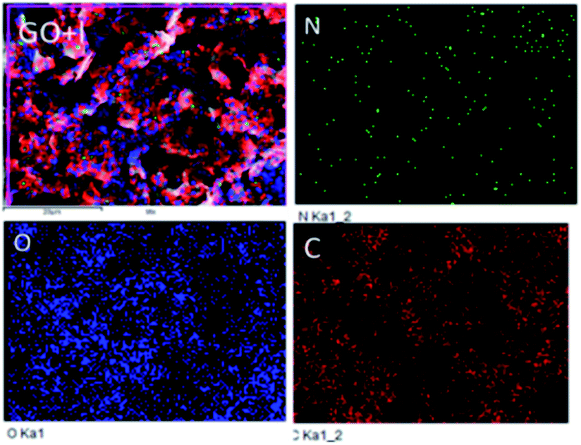
As shown in Fig. 2, in the functionalized GO the amino acid attached via N-atom connection to π-bond is regularly distributed over the graphene oxide sheet. The other elements concentrations are high due to the graphene oxide edge functional groups, whereas the N percentage is lower because the amino acid guest molecules are chemisorbed on the π–π plane of graphene oxide.
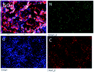 |
| | Fig. 2 Leucine functionalized graphene oxide elemental mapping. | |
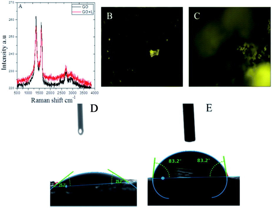
Fig. 3 presents the results of the Raman spectroscopy studies of GO and GO + L functional material carbon disorder.24 The peak appearing at 1230 cm−1 is associated with D and peak at 1540 cm−1 is associated with G bond characteristic, and it is suggested that GO and functional GO materials are regularly formed without any defects due to mild oxidation agent used. In Fig. 3B Raman image of without amino acid functionalizations GO is not bright due to absence of active nitrogen. In Fig. 3C image of amino acid functionalized GO sheet is bright due to presence of active nitrogen groups. However, in Fig. 3D epoxy coated magnesium alloy shows the surface wettability around 25° due to the epoxy coating peel off from alloy surface. In Fig. 3E presence of amino acid functionalized graphene oxide coated magnesium alloy surface is showing high wettability of 83° degrees.25 It helps to avoid aggressive solution interaction with coated surface. The wettability results reveal that amino acid functionalized graphene oxide has excellent hydrophobicity due to the active nitrogen interactions through π-bonds with GO sheet, and thus prevents the aggressive ions penetration to the coated surface.
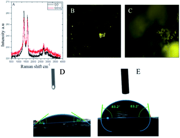 |
| | Fig. 3 (A) Raman studies of GO functional materials, (B) and (C) Raman image of with and without amino acids GO, (D) epoxy coated, and (E) GO + L coated magnesium surface wettabilities. | |
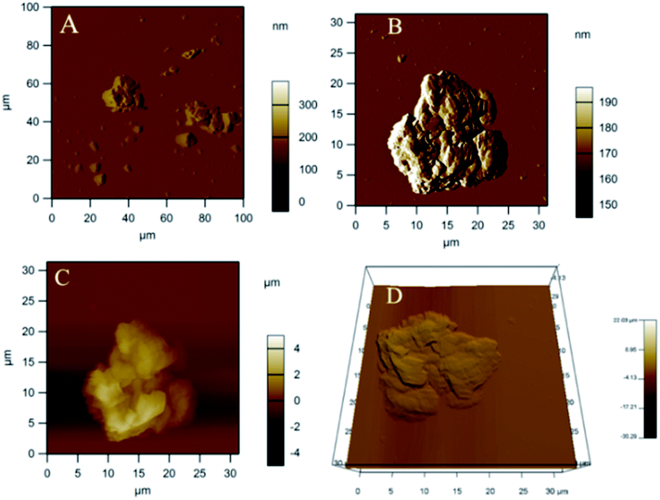
As shown in Fig. 4, AFM leucine functionalized graphene oxide looks like regularly exfoliated from bulk graphite layers by oxidation agent. Fig. 4A of the (GO + L) composite indicates few-layer graphene oxide. And the GO + L composite microstructure shown in Fig. 4B suggests that sheets are less the 10 microns due to the high-pressure hydrothermal reaction.26Fig. 4C indicates that few layer graphene oxide sheets are uniformly exfoliated by ultrasonic energy. The AFM results thus are supported by microscopy studies. As shown in Fig. 5 (XRD of GO and (GO + L)), peak appearing at 2θ = 10° is associated with graphene oxide few layer (002), and peak for GO and GO + L phase is changed which indicates that the GO material is crystalline. The small peak at 2θ = 28° and 2θ = 30° is characteristic peak of -N- functionalized graphene oxide sheet.27 The XRD studies reveal that amino acid functionalized GO sheet has crystalline structure, coherent with microscopy studies.
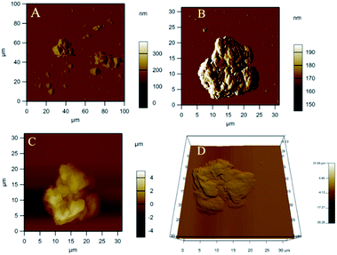 |
| | Fig. 4 AFM studies of leucine functionalized graphene oxide (A) 100 micron area analysis, (B) single GO + L sheet analysed, (C) and (D) GO + L few layer. | |
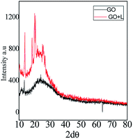 |
| | Fig. 5 XRD of GO and GO + L functionalized materials. | |
3.3. Corrosion inhibition studies
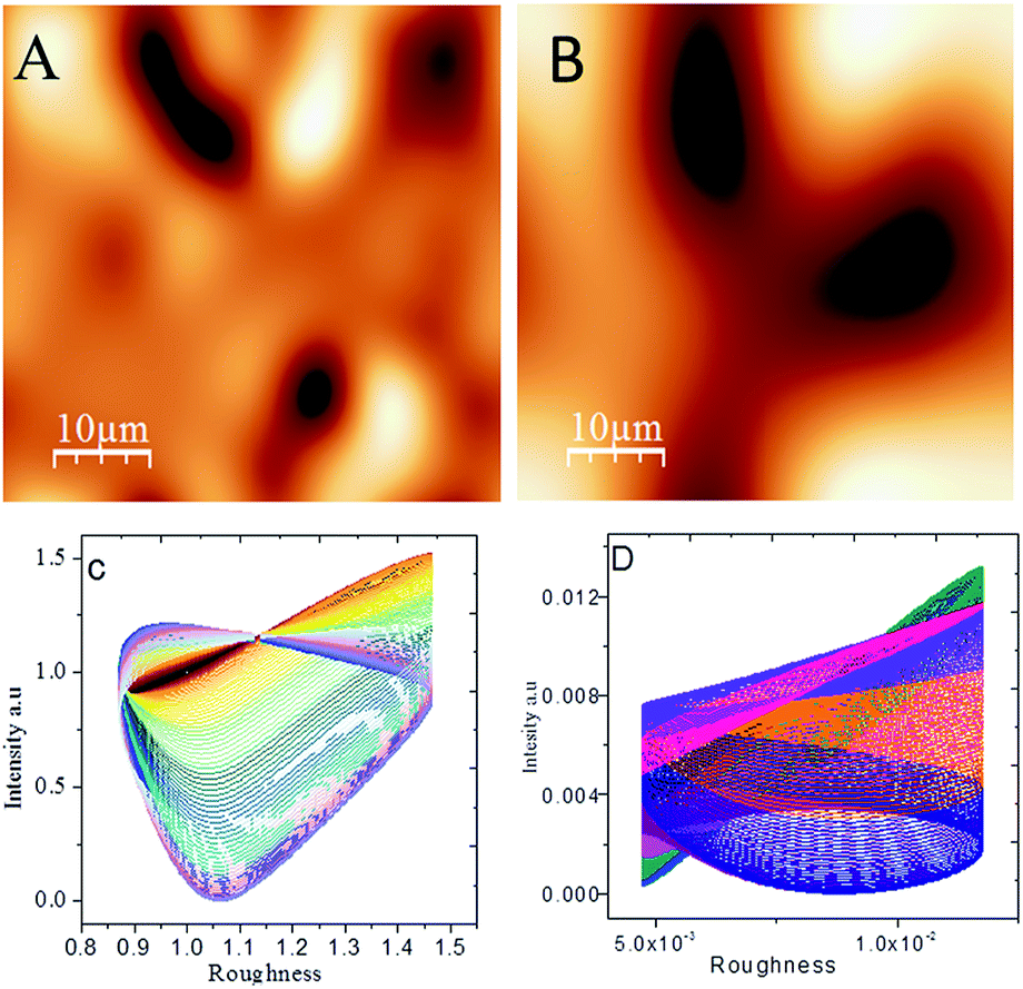
The results of potentiodynamic polarization studies of the epoxy coated Mg alloy and (GO + L) composite coated Mg alloys studied after 48 h immersed in 3.5% NaCl salt medium are presented in Fig. 6A. The conventional epoxy coated Mg alloy has corrosion inhibition decreased due to the epoxy coating poor stability in salt environments. Epoxy coated Mg alloy surface was badly affected due to the chloride attack. Further, corrosion current density value is increased up to 6.260 mA and corrosion potential value is decreased down to 1.420 mV because Mg alloy surface was affected by corrosive ions penetrating to the epoxy coated alloy surface. In the case of (GO + L) coated Mg alloy has strong adsorption on the alloy surface. Hence anodic alloy dissolution and cathodic hydrogen gas evolution have been controlled by (GO + L) composite coating. Although, the corrosion potential is increased as compared with epoxy coating, and corrosion current has also decreased as compared with epoxy coating Mg alloy. Further, the alloy active sites are passivated by the GO functionalized materials.28–32Fig. 6B shows that impedance of epoxy coating Mg alloy Rct value is decreased to 24 Ω and Cdl value is increased to 9.2228 μF which may indicate that Mg alloy undergoes corrosion due to epoxy coating peel off from alloy surface. Meanwhile, for the GO + L coated Mg alloy Rct value is increased up to 38 Ω and Cdl value is decreased to 2.7192 μF due to GO + L materials strong adsorption barrier film on Mg alloy. The corrosion inhibition values are presented in Table 1. As shown in Fig. 6C, GO + L composite coated Mg alloy microstructure is smooth, and localised corrosion is controlled by the composite materials physisorption on Mg alloy surface.33–35 In Fig. 6D it is shown that epoxy coated Mg alloy has pitting on alloy surface, it leads to hydrogen evolution. This is the reason why for the Mg alloy surface localised corrosion was initiated on alloy surface. Fig. 6D shows that epoxy coated Mg alloy microstructure is harshly affected, several cracks appeared on the alloy surface due to the epoxy coating failure.36,37 In Fig. 7 coating thicknesses of epoxy and GO + L coated Mg alloy are shown. Coating fitting χ2 values less than 1 indicate that coating is uniform, and there is no un-uniform surface. The coating values are given in Table 1, the epoxy coating thickness and GO + L coating are almost the same. The coating results support electrochemical studies. As shown in Fig. 8, AFM surface roughness of magnesium alloy, the epoxy coated alloy was corroded and roughness was increased around 2μ due to the chloride ions attack on the alloy surface (Fig. 8B). In Fig. 8A for the GO + L coated Mg alloy no pitting corrosion on surface is shown due to strong barrier layer formed on surface.38,39 In Fig. 8D, epoxy coated Mg alloy shows high surface roughness due to the poor physisorption of epoxy film on alloy surface. Whereas, results shown in Fig. 8C suggested that pitting propagation is controlled by functionalized materials and roughness values are reduced to around 1μ by the GO + L functionalized materials adsorbed on active alloy surface. Further in Fig. 8D it can be seen that pitting propagation is increased due to the absence of active functional group in the epoxy coating and pitting corrosion is increased to around 5μ by attack of chloride ions on alloy surface.
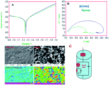 |
| | Fig. 6 (A) polarization, (B) impedance and corrosion inhibition studies and (C)–(E) GO + L coated magnesium alloy and E indicates pitting on surface, and (D)–(F) epoxy coated alloy surface, (F) indicates pitting on surface and (G) impedance curve fitting equivalent circuit. | |
Table 1 Epoxy and GO + L composite coated magnesium alloy corrosion inhibition values
| S. no. |
Coating |
−Ecorr mV |
−ICorr mA |
R
ct Ω |
C
dl μF |
χ
2
|
Å |
| 1 |
Epoxy |
1.420 |
6.260 |
24 |
9.2228 |
1.0167 |
182 |
| 2 |
GO + L |
1.900 |
2.420 |
38 |
2.7192 |
1.9719 |
186 |
 |
| | Fig. 7 The dry coating thickness of epoxy and GO + L coated magnesium alloy. | |
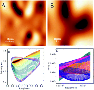 |
| | Fig. 8 AFM images of (A) GO + L coated magnesium alloy, (B) epoxy coated magnesium alloy; roughness plots for (C) GO + L coated magnesium alloy and (D) epoxy coated magnesium alloy. | |
3.4. Quantum chemical studies
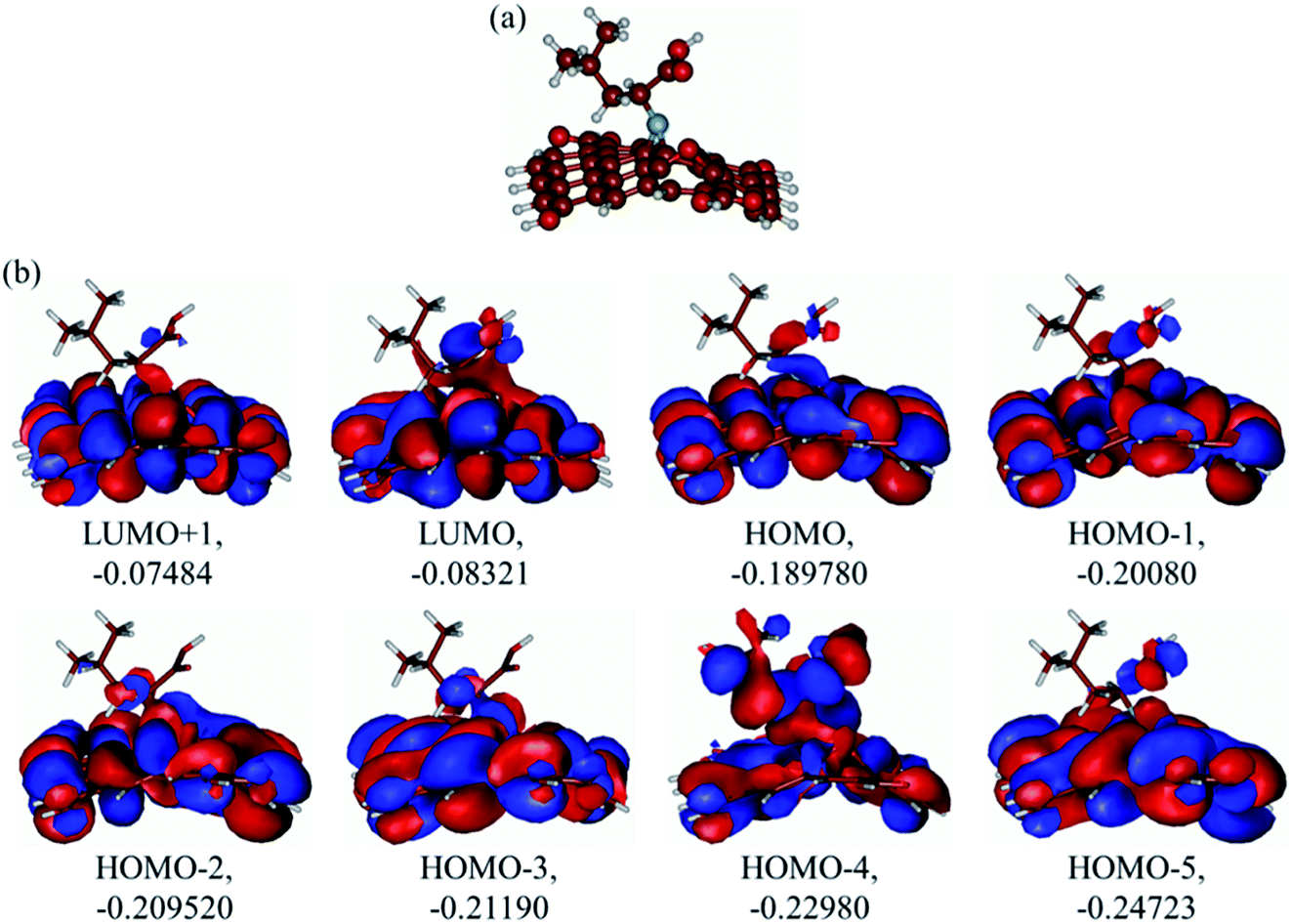
The optimized structure of the GO-leucine model and its several MOs are presented in Fig. 9a and b respectively. As can be seen in Fig. 9a, upon optimization the graphene model layer becomes quite noticeably distorted. However, the leucine molecule keeps its structure and is coordinated to the GO model surface only through the N-atom. Analysis of the several MOs of the GO-leucine model shows that from the HOMO and down to HOMO−4 dominating contributions in the MOs are from the GO moiety, and the leucine molecule contributions are smaller, mainly coming from its N group and –CH2CHCO2H part attached to the N group. The HOMO−4 has very significant contributions from both the GO moiety and leucine. The LUMO has relatively small contributions from the leucine part and dominating contributions from the GO moiety, whereas the LUMO+1 has even smaller leucine contributions. Also, as can be noticed, the HOMO has noticeable contributions from the –CO2H groups, too, which might suggest that the leucine functionalized GO material would be able to absorb on metal surface. Table 2 presents the global reactivity parameters computed using energies of two couples of MOs of the system studied, HOMO & LUMO and HOMO−1 & LUMO−1. As can be seen, the global hardness (η) values of the inhibitor molecule model are quite small and global softness (σ) values are very noticeable, being ca. 115–138 times greater than the global hardness (η) values, which suggests that this inhibitor system would be highly reactive towards oxidizing agents attacking the surface. This is also supported by relatively small energy gap value (ΔE) for the GO–leucine composite material. This narrow gap along with the Frontier orbitals composition suggests that in the amino acid functionalized material electron transfer would occur between graphene surface and leucine molecule acting as inhibitor. Small global electronegativity (χ) and electrophilicity (ω) values suggest that no charge transfer between the metal alloy surface and the GO–leucine system would occur, thus preventing from possible destruction of the metal alloy surface.40–42 The possible reactivity of the leucine molecule is also supported by the results of NBO analysis which showed quite noticeable negative charge accumulation on the atoms of the leucine.
 |
| | Fig. 9 (a) Optimized structure and (b) several unoccupied and occupied molecular orbitals of the graphene oxide model with covalently bound leucine. Energies of MOs given in A.U. | |
Table 2 Global reactivity parameters computed for the graphene oxide model with covalently bound leucine. Values in A.U. A = HOMO & LUMO, B = HOMO−1 & LUMO−1
| |
I
|
A
|
ΔE |
χ
|
σ
|
η
|
ω
|
| A |
0.18978 |
0.08321 |
0.10657 |
0.053285 |
18.767 |
0.136495 |
0.0104 |
| B |
0.20080 |
0.07484 |
0.12596 |
0.06298 |
15.878 |
0.13782 |
0.01439 |
3.5. Corrosion inhibition mechanism
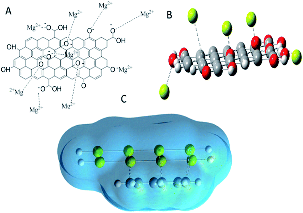
For the inhibition mechanism, we proposed that graphene oxide functionalized by leucine behaves as negatively charged surface. The active magnesium alloy surface is positively charged which is attributed to physisorption on alloy surface as shown in Fig. 10A and B. The physisorption could be improved by blocking active magnesium alloy surface. Hence, as shown in Fig. 8B, alloy surface Mg2+ ions could interact via electrostatic forces with graphene oxide active functional groups, which blocks the corrosive ions diffusion as shown in Fig. 8C. Furthermore, the functionalized materials have multifunctional groups which can improve chemisorption on positively charged magnesium alloy. According to our experimental and DFT studies, amino acid functionalized graphene oxide acts as excellent corrosion barrier layer on magnesium AZ13 alloy.
 |
| | Fig. 10 Proposed mechanism: (A) suggested physisorption of negative charged functionalized GO materials on Mg alloy surface, (B) depiction of Mg2+ state–alloy surface electrostatic interaction, (C) total electrostatic interaction of functionalized graphene oxide materials on Mg alloy. | |
4. Conclusions
The results of the studies of morphology and corrosion inhibition efficiency of the amino acid functionalized graphene oxide materials are presented. The spectroscopy results reveal that respective functional groups are present in the materials. The Raman results suggest that carbon defect contents noticeably decrease. The functionalized materials crystalline structure is confirmed by the XRD. Microscopy studies indicate that GO and GO + L microstructure have nanometer range. The electrochemical results reveal that amino acid functionalized graphene oxide acts as an excellent barrier layer in salt environments. The alloy roughness results suggest that epoxy coating is rougher as compared with GO amino acid composited coated Mg alloy. Furthermore, the amino acid functionalized GO sheet slowed down anodic and cathodic reaction. The computational results corroborate with the experimental studies.
Conflicts of interest
There are no conflicts to declare.
Acknowledgements
N. P. thanks to Central University of Gujarat and Non-NET fellowship and Central Instrument Facility. The authors thank to Dr C. Balasubramanian at the Facilitation Centre for Industrial Plasma Technologies in the Institute for Plasma Research in Gandhinagar for supporting AFM.
References
- Y. J. Wu, X.-B. Chen, G. Williams, J. R. Scully, T. Gengenbach and N. Birbilis, RSC Adv., 2016, 6, 43408–43417 RSC.
- W. S. Chubin He, Y. Wen, Y. Wang and Z. Zhang, RSC Adv., 2016, 6, 113967–113980 RSC.
- J. Liu, X. L. Liu, T. F. Xi and C. C. Chu, J. Mater. Chem. B, 2015, 3, 878–893 RSC.
- Q. Xu, Y. Liu, C. Liu, A. Tian, X. Shi, C. Dong, Y. Zhou and H. Zhou, RSC Adv., 2015, 5, 14458–14464 RSC.
- C. Liu, Q. Li, J. Liang, J. Zhou and L. Wang, RSC Adv., 2016, 6, 30642–30651 RSC.
- H. Zhao, S. Cai, Z. Ding, M. Zhang, Y. Lia and G. Xu, RSC Adv., 2015, 5, 24586–24590 RSC.
- S. Agarwal, M. Morshed, M. N. Labour, D. Hoey, B. Duffy, J. Curtin and S. Jaiswa, RSC Adv., 2016, 6, 113871–113883 RSC.
- N. Palaniappan, I. S. Cole, F. Caballero-Briones, K. Balasubaramanian and C. Lal, RSC Adv., 2018, 8, 34275–34286 RSC.
- N. Palaniappan, I. S. Cole, F. Caballero-Briones, S. Manickam, C. Lal and J. Sathiskumar, RSC Adv., 2019, 9, 8537–8545 RSC.
- H. A. Sorkhabi, M. R. Majidi and K. Seyyedi, Appl. Surf. Sci., 2004, 225, 176–185 CrossRef.
- N. H. Helal and W. A. Badawy, Electrochim. Acta, 2011, 56, 581–6587 CrossRef.
- M. Selvam, K. Saminathan, P. Siva, P. Saha and V. Rajendran, Mater. Chem. Phys., 2016, 172, 129–136 CrossRef CAS.
- L. B. Tong, J. B. Zhang, C. Xu, X. Wang, S. Y. Song, Z. H. Jiang, S. Kamado, L. R. Cheng and H. J. Zhang, Carbon, 2016, 109, 351 CrossRef.
- F. Fan, C. Zhou, X. Wang and J. Szpunar, ACS Appl. Mater. Interfaces, 2015, 7, 27271–27278 CrossRef CAS.
- Z. Qiu, R. Wang, J. Wu, Y. Zhang, Y. Qu and X. Wu, RSC Adv., 2015, 5, 44149–44159 RSC.
-
M. J. Frisch, G. W. Trucks, H. B. Schlegel, et al., Gaussian 09: ES64L-G09RevD.01 24-Apr-2013, Gaussian, Inc., Wallingford CT, 2013 Search PubMed.
-
R. G. Parr, W. Yang, Density-functional theory of atoms and molecules, Oxford University Press, Oxford, 1989 Search PubMed.
- R. Ditchfield, W. J. Hehre and J. A. Pople, Self-consistent molecular-orbital methods. IX. An extended Gaussian-type basis for molecular-orbital studies of organic molecules, J. Chem. Phys., 1971, 54, 724–728 CrossRef CAS.
- A. E. Reed, R. B. Weinstock and F. Weinhold, Natural-population analysis, J. Chem. Phys., 1985, 83, 735–746 CrossRef CAS.
- G. Schaftenaar and J. H. Noordik, Molden: a pre- and post-processing program for molecular and electronic structures, J. Comput. Aided Mol. Des., 2000, 14, 123–134 CrossRef CAS.
- J. Ding, H. Zhao, D. Ji, B. Xu, X. Zhao, Z. Wang, D. Wang, Q. Zhou and H. Yu, J. Mater. Chem. A, 2019, 7, 2864–2874 RSC.
- M. Bagherzadeh, Z. S. Ghahfarokhib and E. Ghiamati Yazdi, RSC Adv., 2016, 6, 22007–22015 RSC.
- C. K. Chua and M. Pumera, Chem. Soc. Rev., 2014, 43, 291–312 RSC.
- P. Du, J. Wang, G. Liu, H. Zhao and L. Wang, Mater. Chem. Front., 2019, 3, 321–330 RSC.
- J. Fenga and Z. Guo, Nanoscale Horiz., 2019, 4, 339–364 RSC.
- Z. Sofer, P. Simek, O. Jankovsky, D. Sedmidubsky, P. Beran and M. Pumera, Nanoscale, 2014, 6, 13082–13089 RSC.
- S. M. Beladi-Mousavi and M. Pumera, Chem. Soc. Rev., 2018, 47, 6964–6989 RSC.
- S. Mayavan, T. Siva and S. Sathiyanarayanan, RSC Adv., 2013, 3, 24868–24871 RSC.
- Y. Song, Y. Liu, H. b. Jiang, S. y. Li, C. Kaya, T. Stegmaier, Z. w. Han and L. q. Ren, Nanoscale, 2018, 10, 3813–3822 RSC.
- S. Dea and J. L. Lutkenhaus, Green Chem., 2018, 20, 506–514 RSC.
- J. Ding, H. Zhao, X. Zhao, B. Xu and H. Yu, J. Mater. Chem. A, 2019, 7, 13511–13521 RSC.
- M. Mo, W. Zhao, Z. Chen, E. Liua and Q. Xuea, RSC Adv., 2016, 6, 7780–7790 RSC.
- R. Ramachandran and M. Nosonovsky, Phys. Chem. Chem. Phys., 2015, 17, 24988–24997 RSC.
- C. Wu, Q. Liu, J. Liu, R. Chen, K. Takahashi, L. Liu, R. Li, P. Liu and J. Wang, New J. Chem., 2017, 41, 12767–12776 RSC.
- E. G. Yazdi, Z. S. Ghahfarokhia and M. Bagherzadeh, New J. Chem., 2017, 41, 12470–12480 RSC.
- C. Liu, S. Qiu, P. Du, H. Zhao and L. Wang, Nanoscale, 2018, 10, 8115–8124 RSC.
- W. Sun, L. Wang, T. Wu, Y. Pana and G. Liu, J. Mater. Chem. A, 2015, 3, 16843–16848 RSC.
- S. J. R. Prabakar, C. Park, A. B. Ikhe, K. S. Sohn and M. Pyo, ACS Appl. Mater. Interfaces, 2017, 50, 43767–43773 CrossRef.
- N. Baig, D. S. Chauhan, T. A. Saleha and M. A. Quraish, New J. Chem., 2019, 43, 2328–2337 RSC.
- Y. H. Yu, Y. Y. Lin, C. H. Lin, C. C. Chan and Y. C. Huang, Polym. Chem., 2014, 5, 535–550 RSC.
- H. T. Larijani, M. D. Ganji and M. Jahanshahi, RSC Adv., 2015, 5, 92843–92857 RSC.
- R. K. Gupta, M. Malviya, C. Verma, N. K. Gupta and M. A. Quraishi, RSC Adv., 2017, 7, 39063–39074 RSC.
|
| This journal is © The Royal Society of Chemistry 2019 |
Click here to see how this site uses Cookies. View our privacy policy here. 
 Open Access Article
 This Open Access Article is licensed under a Creative Commons Attribution-Non Commercial 3.0 Unported Licence
 *a,
I. S.
Cole
*a,
I. S.
Cole