
 Open Access Article
 This Open Access Article is licensed under a Creative Commons Attribution-Non Commercial 3.0 Unported Licence
Slurry nebulisation ICP-MS direct determination of high field strength elements (Nb, Ta, Zr, and Hf) in silicate rocks
Rui
Tong
and
Wei
Guo
 *
*
State Key Laboratory of Biogeology and Environmental Geology, China University of Geosciences, Wuhan, 430074, P. R. China. E-mail: Wei.Guo@cug.edu.cn; Tel: +86-027-67848602
First published on 10th October 2019
Abstract
A simple, rapid, and reliable method was developed for the direct determination of four high field strength elements (HFSEs, namely, Nb, Ta, Zr, and Hf) in refractory silicate rocks using slurry nebulisation inductively coupled plasma mass spectrometry (ICP-MS). Samples were dispersed in a 0.2% Triton X-100 solution by wet-grinding with a tissue cell-destroyer, and 90% of the particles in the slurry were found to be less than 1.5 μm in diameter during 90 s of milling. Fine slurry was directly introduced into ICP and detected by mass spectrometry. The behaviors of different particle size distributions in the transportation and ionisation processes were investigated. Results indicated that the cut-off size for particle efficient transport (in the sample introduction system) and complete ionization (in the ICP) was approximately 8 μm and 4 μm, respectively. Our fine slurries (mean particle size, <1.0 μm) showed comparable mass transfer efficiency and ionisation efficiency to aqueous standards. Calibration can be carried out via aqueous standards, with a limit of quantification (LOQ) in the range of 18–30 ng g−1. Satisfactory accuracy (recovery, 91 to 103%) and precision (RSD, 0.9 to 6.3%) were verified by analysis of a series of silicate rock certified reference materials (CRMs).
Introduction
Zr–Hf and Nb–Ta form two pairs of “twin” elements that are known as “high field strength elements (HFSEs)”, and these are of great interest in geochemistry and cosmochemistry.1 The ratios (Zr/Nb or Hf/Ta) have been widely used to monitor the degree of depletion/enrichment of mantle reservoirs relative to the primitive mantle, because of the different affinities of Zr (Hf) and Nb (Ta) for silicate melts.2 Compared with the rock involved carbonatitic magmas or associated with fluorine-rich complexing fluids, the ratios of Zr/Hf and/or Nb/Ta show very limited variations in rocks formed by processes involving partial melting of silicate solids or fractional crystallisation of silicate liquids.3,4 Therefore, it is important to acquire accurate and precise data for these HFSEs at trace levels in silicate rocks.X-ray fluorescence spectrometry (XRF) and instrumental neutron activation analysis (INAA) have been widely used for the determination of Zr–Nb or Hf–Ta, respectively.5,6 However, these techniques cannot be used to analyse these four elements simultaneously because of their inadequate sensitivity for many geological materials.1 A highly sensitive and multi-element simultaneous analytical method based on inductively coupled plasma mass spectrometry (ICP-MS) has been developed to measure the contents of HFSEs and other trace elements over the past three decades.7–21 The dissolution of solid samples (by acid digestion or alkaline fusion) is required before materials are introduced into the ICP-MS instrument as aerosols of aqueous solutions. There are presently two difficulties encountered when using silicate digestion procedures for HFSEs measurements. (i) First, HFSEs are generally present in insoluble mineral phases, and thus, high pressure closed acid digestion or alkaline fusion methods are needed to digest the silicate rock samples completely. However, these methods either require excessive times (>48 hours) or complicated separation procedures to decrease the high total dissolved solid (TDS) content of the final solution.22–24 (ii) Second, HFSEs easily undergo hydrolysis and form insoluble compounds in the final solution of samples (e.g. Nb and Ta), which results in poor accuracy and precision for these elements compared to others.25,26 To overcome the hydrolysis problem, researchers have demonstrated that HFSEs can be stabilized in solution by adding hydrofluoric acid (HF) for forming soluble HFSE–Fn2−,27–29 but F− can easily form fluoride precipitates with matrix elements (e.g. Al, Mg, and Ca), which may adsorb HFSEs from the HF solution and ultimately result in the loss of the targets.30–32 Organic compounds (e.g. tartaric acid, citric acid, oxalic acid, malic acid or alpha-hydroxy acids)33,34 also have been employed to form soluble HFSE-complexes in the final solution; however, it is more difficult to purify these organic compounds than that of the HNO3 or HF to avoid high reagent blanks.
An alternative technique based on the direct introduction of aqueous suspensions of finely powdered solids (5–10 μm), termed slurry nebulisation, has been successfully applied to the direct ICP optical emission spectrometry (ICP-OES) analyses of refractory materials.35–39 The slurry nebulisation technique offers unique advantages over other types of solid sample introduction methods such as laser ablation (LA)40 or electrothermal evaporation (ETV)41 because it has the potential for calibration with aqueous standards, together with essentially a conventional pneumatic sample introduction system.42 Although ICP-MS typically presents a three-order of magnitude sensitivity and simple spectra better than those from ICP-OES, there are few reports43–45 in the literature of slurry nebulisation in ICP-MS, probably due to its low intolerance for matrix effects owing to particle deposition on the sampler cone, and the consequent need to dilute that impairs the detection capability.46 Only one study based on the slurry nebulisation ICP-MS technique to analyse Nb and Ta in 13 geological certified reference materials (CRMs) was found.45 In that work, a minimum of 15 h grinding was required to obtain particles 4 μm in diameter, and poor accuracy (the measured errors >50%) was found for most of the geological CRMs.45 The reason may have been that the particle sizes of the geological samples were too large to be transported and/or ionised when they were introduced into the ICP plasma. Thus, more precise procedures should be established for slurry preparation to use this system for the routine analysis of trace levels of HFSEs in silicate samples.
The ability to calibrate by using simple aqueous standards would be a very important feature of the slurry nebulisation method for direct elemental analysis of solid samples, because solid standard samples with both complete matrix-matched and similar particle size distribution characteristics are not readily available. However, previous studies by ICP-OES on the direct analysis of slurries indicated there is a limitation associated with the use of solution standards.47,48 Compared to the signal response of Cr and Ni obtained by solution nebulisation in plasma during the ICP technique, only 30–50% of the signal response of Cr and Ni was obtained by slurry nebulisation with a particle size of 6 μm.47 Mochizuki et al.48 observed that the relative signal responses (RSRs) of rare earth elements were improved up to 61–83% when a smaller particle size of 3 μm was adopted. Although long milling times (>8 h) were required to obtain the desired particle size range (3 to 6 μm), an obvious trend of increases in the RSR with decreases in the particle size was observed.48 Therefore, a value of the RSR close to 100% is a good prerequisite for the direct use of simple aqueous standards to calibrate the slurry introduction technique. The aim of this study was to develop a reliable slurry nebulisation ICP-MS method that can be used to obtain accurate data on the content of HFSEs in silicate rocks. A fast grinding method using a tissue cell-destroyer was employed to produce fine particles of <1.0 μm (mean particle size, Dm) in diameter during 90 s of milling. The behavior of different sized particles in the silicate slurry during the transportation and ionization processes of suspension nebulisation ICP-MS was investigated in detail. Results obtained by slurry nebulisation ICP-MS with aqueous standard calibrations were evaluated through comparisons with the certified values for a series of silicate rock certified reference materials.
Experimental
Instrumentation, reagents, and standards
All measurements were carried out on an Agilent 7700× single quadrupole ICP-MS (Palo Alto, CA) with a conical U-series nebuliser (Glass Expansion, Australia) and a Peltier-cooled Scott-type double pass spray chamber (2 °C). The optimised operating parameters for ICP-MS are listed in Table 1. A Mastersizer 3000 laser diffraction analyser (Malvern PAnalytical Ltd., England) with a measurement range extending from 0.01 to 3500 μm was applied for the determination of the particle size distribution. A Tissue Cell-Destroyer 1000 (Hubei Xinzongke Viral Disease Control Bio-Tech Ltd., China) was used to obtain the series of the desirable particle sizes of silicate rocks by changing the mill time.| ICP-MS | Agilent 7700× |
|---|---|
| RF power, W | 1500 |
| Plasma-gas flow, L min−1 | 16 |
| Auxiliary-gas flow, L min−1 | 1.0 |
| Nebulizer-gas flow, L min−1 | 0.9 |
| Sampling depth, mm | 8 |
| Sweeps | 25 |
| Reading per replicate | 3 |
| Dwell time, ms | 50 |
| Monitored isotopes | 90Zr, 93Nb, 178Hf, and 181Ta |
High-purity water (resistivity of 18.2 MΩ cm) obtained from a Millipore water purification system (Darmstadt, Germany) was used throughout for the preparation of samples and standard solutions. The 1000 μg mL−1 standard solutions of single elements (e.g. Nb, Ta, Zr, Hf, Rh, and Re) were obtained from the National Centre for Analysis and Testing of Steel Materials (Beijing, China). Ultrapure Triton-100 was purchased from Alfa Aesar Ltd (Tianjin, China). A series of CRMs covering different types of silicate rocks (e.g. AGV-2, BCR-2, BHVO-2, GBW07103-07, GBW07109-13, and GBW07121-25) were purchased from the United States Geological Survey (USGS, USA), and the Institute of Geophysical and Geochemical Exploration (IGGE, China).
Slurry preparation
A total of 0.010 g of dry silicate CRMs (<74 μm) were ground up with the tissue cell-destroyer together with 5.0 mL 0.2% m/v Triton-100 and 0.5 g shaking beads (o.d. = 0.1 mm). After milling by the optimised procedures (Table 2), the slurry was diluted to 100 mL with the 0.2% m/v Triton-100 solution. Then, it was directly introduced into the ICP and analysed by MS. The particle size distribution in the slurry was examined by a Mastersizer 3000 laser diffraction analyser. The mean particle size was 1.0 μm, and 90% of the particles in the slurry were smaller than 1.5 μm in diameter during the 90 s of milling.| Parameter | Optimum values |
|---|---|
| Rotate speed, rpm | 5500 |
| Each mill time, s | 10 |
| Interval time, s | 10 |
| Total mill time, s | 90 |
| Temperature, °C | 37 |
Transport and ionisation behavior of slurry particles
The particle size in slurry affects the transport and/or ionisation efficiency and ultimately the sensitivity of the analytes. In this work, the upper limit of the particle size that can be transported into the ICP torch and completely ionised in the ICP was determined. The transport behavior of slurry particles was tested as follows: (i) slurry with a particle size of 15 μm (mill time of about 30 s) was introduced into the nebuliser, and then, the produced aerosol was trapped in water and measured by the Mastersizer 3000 analyzer; (ii) after the slurry aerosol passed through the spray chamber and the torch injector, it was trapped in water and measured by the Mastersizer 3000 analyser, respectively. The relative ionisation efficiency (RIE) was obtained by calculating the ratio of the signal intensity of the HSFEs in the particle slurry to those in aqueous solution containing equivalent concentrations.Results and discussion
Reduction of the silicate particle size
The particle size obtained by grinding depends on the milling time for the refractory silicate rocks, and it can have a great influence on the accuracy and precision. Following the first study on the analysis of silicate rocks using the slurry nebulisation technique, Jarvis and Williams45 found that the grain-size distribution for diorite samples varies greatly. After 2 h of grinding, there was a wide range of particle sizes (about 15% of particles >60 μm), and after 15 h of grinding, the required particle size with a mean size of 2–4 μm was obtained.45 Another paper reported that it took 5 h to obtain good quantitative recovery levels (>90% for Na and Ta) for silicate geological samples when using slurry sampling ICP-OES with a planetary ball mill.33 In this work, a new tissue cell-destroyer was employed to investigate the relationship of the milling time and particle size of the silicate rocks. As shown in Fig. 1a, the mean diameter (Dm) for andesite AGV-2 decreased with the increasing mill time, and no significant changes were observed when the mill time was set to more than 90 s. When the mill time was selected as 90 s, the curve of the particle size distribution showed that homogenisation occurred within narrow size range of 0.5 to 1.5 μm for 90% of the particles (Fig. 1b).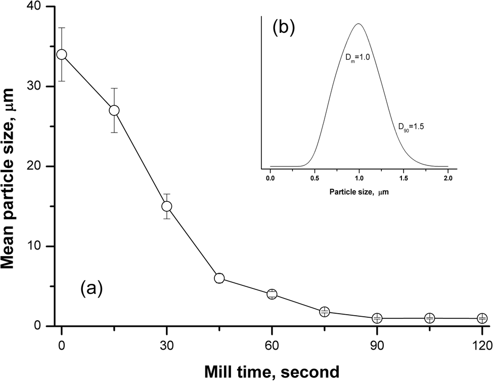 | ||
| Fig. 1 (a) Effect of mill time on the mean particle diameter (Dm) for andesite AGV-2 certified reference material, and (b) the homogenization of particle size distributions at 90 s mill time. D90 = 1.5 μm: 90% of the particles in the slurry were smaller than 1.5 μm in diameter. | ||
Effect of particle size on transport efficiency
Some researchers have reported that only particles less than 10 μm could contribute to the analyte emission signal in ICP-OES.35,49 Fine particles preferentially migrate to the plasma through selective transport because of the order-sorting of the spray chamber and gravity effects. In order to investigate the transport behavior of the silicate particles, the upper size limit of the particles transported to the different parts of the introduction system (e.g. chamber and torch) was evaluated. As described in the Experimental section, the size distributions of the slurry aerosols collected at the outlet of the nebuliser, outlet of the spray chamber, and outlet of the torch injector were determined, respectively. As shown in Fig. 2a, the size distribution of particles collected at the torch outlet were obviously smaller than those of the original slurry, and the cut-off size (D90) reduced from 23 to 8 μm. We also found that the size distribution of particles collected at the torch outlet displayed no distinct difference from those of the spray chamber outlet, and the size distribution of particles was almost the same between the slurry aerosols collected from the nebuliser outlet and the original slurry (Fig. 2a). The D90 values of the particles were ordered as follows: 23 (original slurry) = 23 (nebulizer outlet) > 8.1 (spray chamber outlet) > 8.0 (torch outlet). The upper size limit (D90) of the silicate particles transported to the plasma during the ICP method was approximately 8 μm, which is in accordance with the results that ranged from 7 to 10 μm for ceramic materials.46 This means that silicate particles with a size less than 8 μm can reach the plasma, and thus, our used particle mean size of 1.0 μm (D90 = 1.5 μm) was confirmed to be small enough for slurry nebulisation ICP-MS.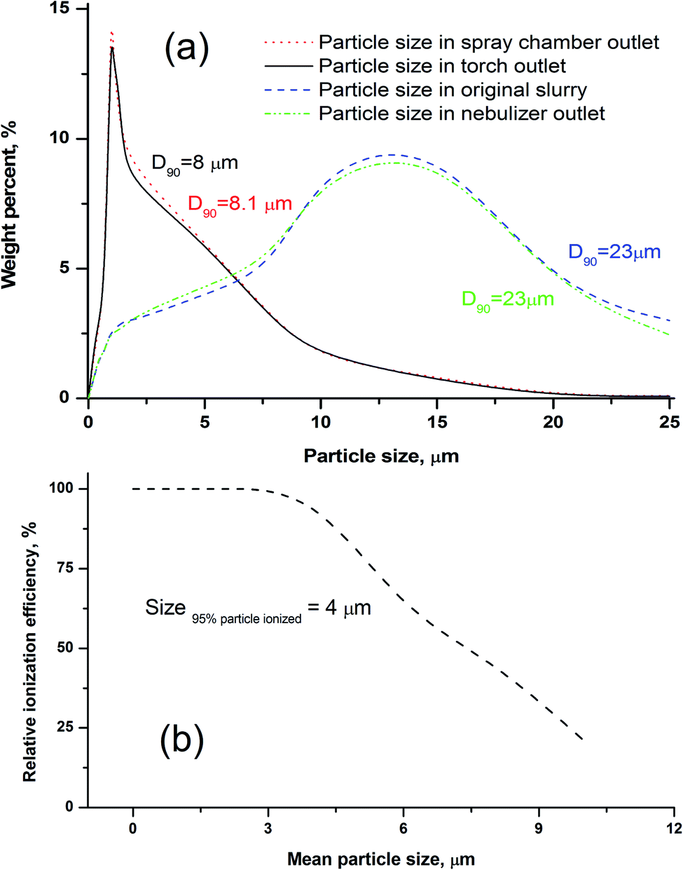 | ||
| Fig. 2 (a) Particle size distributions of the slurry aerosol collected outlet of the ICP torch, spray chamber outlet, nebulizer outlet, and the original slurry; (b) the effect of particle sizes on the relative ionisation efficiency (RIE) for andesite AGV-2. D90 means 90% of the particles in the slurry were smaller than XX μm in diameter. Relative ionization efficiency (RIE), obtained by calculating the ratios of the signal intensity of the HSFEs in particle slurry to those in aqueous solution containing equivalent concentration. | ||
Effect of particle size on the ionisation efficiency
Another important factor to ensure the consistency of the ion sensitivity between the slurry nebulisation and aqueous nebulisation is the ionisation behaviour in plasma during the ICP-MS method. Generally, the finer the particle aerosol is, the easier it is to be ionised. In this work, the RIE was invoked to investigate the effects of particle size on target ionisation. The RIE percentages of andesite AGV-2 powders in different particle sizes were simply calculated by eqn (1) as follows: | (1) |
The effects of particle size on the RIE percentages of AGV-2 slurry powders are shown in Fig. 2b. The upper limit of the silicate particle size that can be completely ionised (RIE, >95%) in the plasma was approximately 4 μm. The ionisation efficiency decreased with the increasing particle size, and only about 48% of the particle mass could be ionised at a particle size of 8 μm. Our calculated size of the complete ionisation (4 μm) was obviously smaller than that of complete vaporisation (7 μm) reported by Wang et al.36 This can be explained by the fact that the complete ionisation of particles (for ICP-MS) requires more energy than particle evaporation (for ICP-OES). The results indicated that the HSFEs in the fine silicate slurry (mean particle size of 1.0 μm) can be completely ionised in ICP. As shown in Fig. 3, differences in ICP-MS sensitivity between the aqueous solution and the fine slurry were less than 5%, and these levels were deemed acceptable for quantification purposes. This finding partly resulted from the almost identical behavior of the material during transport and ionisation.
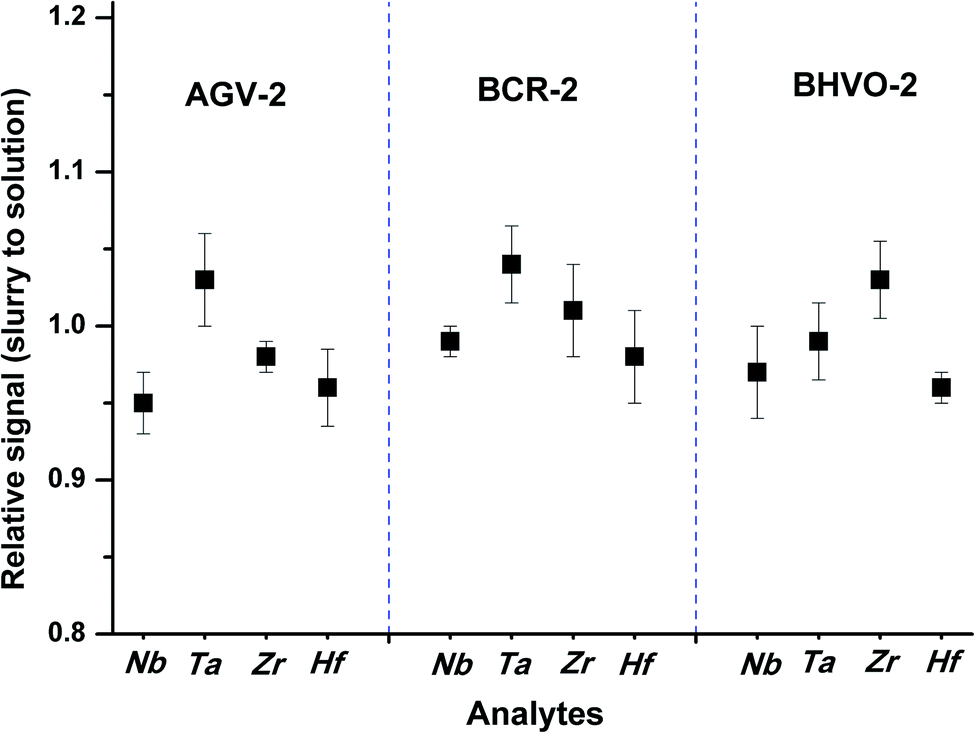 | ||
| Fig. 3 Sensitivity differences for Nb, Ta, Zr, and Hf between the slurries of rock reference materials (AGV-2, BCR-2, and BHVO-2) and the aqueous solution containing equivalent concentration. | ||
Analytical performances
Calibration curves of the standard aqueous solutions were constructed in the range of 0.1–200 ng mL−1 for the analytes. Satisfactory results were obtained for the linear correlation coefficient (R2 > 0.999). The limit of quantification (LOQ) for the HSFEs was calculated as 10 times the standard deviation of 10 procedure blank measurements (taken at a 1000 times dilution), respectively. The LOQ values for this method (18–30 ng g−1) were comparable to those for solution nebulisation ICP-MS following high pressure closed acid digestion (11–42 ng g−1); however, the proposed slurry nebulisation ICP-MS method is simple, fast, easy to operate, and does not need a labour-intensive and time-consuming sample digestion procedure.Analysis of rock CRMs
To evaluate the accuracy and precision of the rapid method, a series of silicate rock CRMs were analysed by the proposed slurry nebulisation ICP-MS method. Fig. 4 shows the measured values and the certified values for these CRMs. The certified values were taken from the website of GeoReM50 and the China Geological Reference Materials Data Sharing Service System,51 respectively. The measured values were in good agreement with the reference values (recovery, 91 to 103%), and the precision (RSD, n = 3) ranged from 0.9 to 6.3% for HSFE contents of 0.18 to 1540 μg g−1.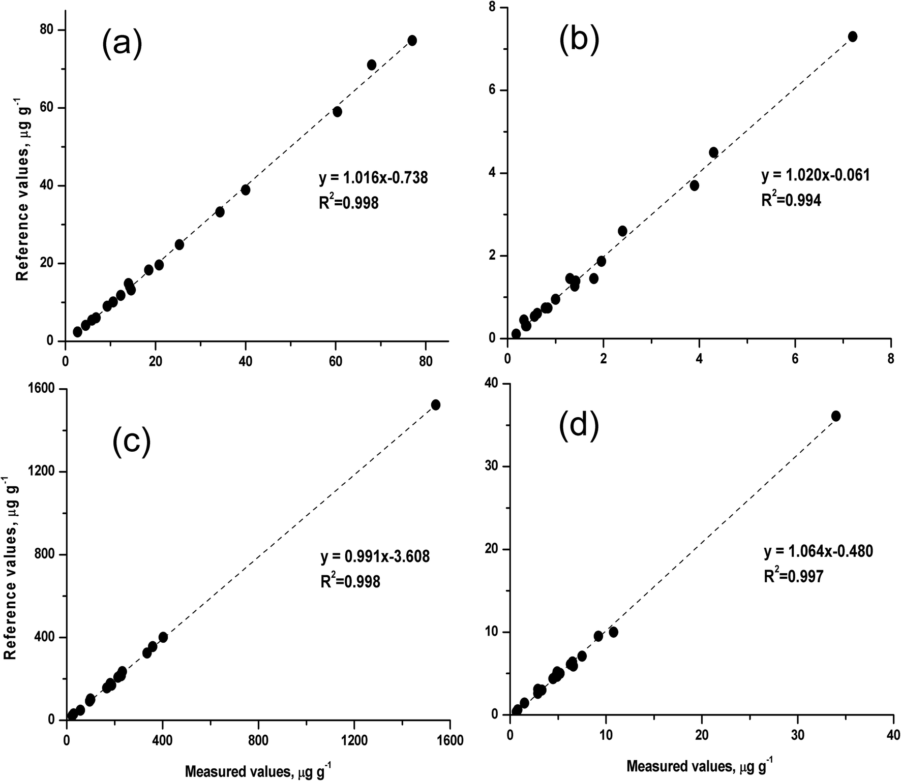 | ||
| Fig. 4 Comparison of the measured values and the certified values for 18 silicate rock certified reference materials (CRMs). | ||
Conclusion
Ultra-fine silicate particles (mean particle size, <1.0 μm) were obtained by wet-grinding with a tissue cell-destroyer during 90 s of milling. Our experiments indicated that the fine silicate slurries with a particle size of <4 μm showed comparable transportation efficiencies and ionisation efficiencies with the aqueous standard solutions. Calibrations for slurry nebulisation ICP-MS were simply carried out by using aqueous solution standards without any other procedures (i.e. internal standards or correction factors). Satisfactory measurement results for 18 rock CRMs obtained from slurry nebulisation ICP-MS were in good agreement with the certified values. This technique can therefore provide a good alternative for the rapid determination of Nb, Ta, Zr, and Hf in refractory silicate rocks.Conflicts of interest
There are no conflicts to declare.Acknowledgements
Financial support from the National Key Research and Development Program of China (No. 2016YFE0203000), the National Natural Science Foundation of China (No. 41873072, and 41521001), and the Fundamental Research Funds for the Central Universities, China University of Geosciences (Wuhan) (No. CUG180603).References
- X. J. Yang and C. Pin, Anal. Chim. Acta, 2002, 458, 375–386 CrossRef CAS.
- A. J. Erlank and E. J. D. Kable, Contrib. Mineral. Petrol., 1976, 54, 281–291 CrossRef CAS.
- R. Rudnick, W. F. McDonough and B. W. Chappell, Earth Planet. Sci. Lett., 1993, 114, 463–478 CrossRef CAS.
- L. Rimbault, G. Meyer and M. Treuil, Bull. Miner., 1987, 110, 591–601 CrossRef.
- U. El-Ghawi, N. Vajda and G. Patzay, J. Radioanal. Nucl. Chem., 1999, 241, 605–616 CrossRef CAS.
- S. Waheed, N. Siddique and Y. Faiz, Geostand. Geoanal. Res., 2013, 37, 197–205 CrossRef CAS.
- G. Bayon, J. A. Barrat, J. Etoubleau, M. Benoit, C. Bollinger and S. Revillon, Geostand. Geoanal. Res., 2009, 33, 51–62 CrossRef CAS.
- C. Xiong, M. He and B. Hu, Geostand. Geoanal. Res., 2009, 33, 385–396 CrossRef CAS.
- E. V. Smirnova, B. Flem, E. A. Anchutina, I. N. Mysovskaya, V. I. Lozhkin and L. L. Petrov, Geostand. Geoanal. Res., 2010, 34, 49–65 CrossRef CAS.
- S. L. Sun and J. Li, Microchem. J., 2015, 119, 102–107 CrossRef CAS.
- G. Tel-Cayan, Z. Ullah, M. Ozturk, M. Yabanli, F. Aydin and M. E. Duru, At. Spectrosc., 2018, 39, 29–37 CAS.
- N. M. Karaaslan and M. Yaman, At. Spectrosc., 2018, 39, 16–21 Search PubMed.
- M. Satyanarayanan, V. Balaram, S. S. Sawant, K. S. V. Subramanyam, G. V. Krishna, B. Dasaram and C. Manikyamba, At. Spectrosc., 2018, 39, 1–15 CAS.
- M. Vannuci-Silva, E. D. da Silva, M. C. Artal, A. dos Santos, F. Silva, G. D. Umbuzeiro and S. Cadore, At. Spectrosc., 2018, 39, 67–74 CAS.
- E. Arica, B. Yuksel, I. Yener, I. Dolak, E. Gok and E. Yilmaz, At. Spectrosc., 2018, 39, 62–66 CAS.
- S. Z. Chen, S. P. Zhu and D. B. Lu, At. Spectrosc., 2018, 39, 55–61 CAS.
- K. A. Vance, A. Makhmudov, G. Shakirova, H. Roenfanz, R. L. Jones and K. L. Caldwell, At. Spectrosc., 2018, 39, 95–99 CAS.
- M. V. B. Krishna, S. Chappa, K. Chandrasekaran, D. Karunasagar and A. K. Pandey, At. Spectrosc., 2018, 39, 142–150 CAS.
- X. B. Yin, X. Y. Wang, S. Chen, Y. Ma, G. Kun and Z. G. Zeng, At. Spectrosc., 2018, 39, 137–141 CAS.
- B. K. Nagar, M. K. Saxena and B. S. Tomar, At. Spectrosc., 2018, 39, 185–190 CAS.
- B. Yuksel and E. Arica, At. Spectrosc., 2018, 39, 179–184 CAS.
- R. Gogue, Fresenius' J. Anal. Chem., 1992, 344, 326–333 CrossRef.
- G. E. M. Hall and J. C. Pelchat, J. Anal. At. Spectrom., 1990, 5, 339–349 RSC.
- X. L. Ou, C. Z. Huang, B. Hu and Z. C. Jiang, Geostand. Geoanal. Res., 2006, 30, 97–105 CrossRef.
- H. P. Longerich, G. A. Jenner, B. J. Fryer and S. E. Jackson, Chem. Geol., 1990, 83, 105–118 CrossRef CAS.
- C. Münker, Chem. Geol., 1998, 144, 23–45 CrossRef.
- A. Makishima, E. Nakamura and T. Nakano, Geostand. Newsl., 1999, 23, 7–20 CrossRef CAS.
- S. Weyer, C. Münker, M. Rehkämper and K. Mezger, Chem. Geol., 2002, 187, 295–313 CrossRef CAS.
- W. Zhang, Z. C. Hu, Y. S. Liu, L. Chen, H. H. Chen, M. Li, L. S. Zhao, S. H. Hu and S. Gao, Geostand. Geoanal. Res., 2012, 36, 271–289 CrossRef CAS.
- R. Tanaka, A. Makishima, H. Kitagawa and E. Nakamura, J. Anal. At. Spectrom., 2003, 18, 1458–1463 RSC.
- W. Zhang, Z. C. Hu, Y. S. Liu, H. H. Chen, S. Gao and R. M. Gaschnig, Anal. Chem., 2012, 84, 10686–10693 CrossRef CAS.
- W. Zhang, L. Qi, Z. C. Hu, C. J. Zheng, Y. S. Liu, H. H. Chen, S. Gao and S. H. Hu, Geostand. Geoanal. Res., 2016, 40, 195–216 CrossRef CAS.
- X. J. Song, T. C. Duan, P. G. Guo and H. T. Chen, Microchem. J., 2006, 84, 22–25 CrossRef CAS.
- M. Biver and M. Filella, Geostand. Geoanal. Res., 2018, 42, 395–401 CrossRef CAS.
- Z. Wang and P. Y. Yang, J. Anal. At. Spectrom., 2014, 29, 2091–2103 RSC.
- Z. Wang, J. Y. Zhang, H. J. Zou, M. Dong, D. R. Qiu and P. Y. Yang, Talanta, 2013, 107, 338–343 CrossRef CAS.
- Z. Wang, D. R. Qiu, G. Y. Tao and P. Y. Yang, J. Anal. At. Spectrom., 2009, 24, 1258–1261 RSC.
- M. Mujuru, R. I. McCrindle and N. Panichev, J. Anal. At. Spectrom., 2009, 24, 494–501 RSC.
- L. Halicz, I. B. Brenner and O. Yoffe, J. Anal. At. Spectrom., 1993, 8, 475–480 RSC.
- Y. T. Li, W. Guo, Z. C. Hu, L. L. Jin, S. H. Hu and Q. H. Guo, J. Agric. Food Chem., 2019, 67, 935–942 CrossRef CAS.
- A. S. Henn, E. M. M. Flores, V. L. Dressler, M. F. Mesko, J. Feldmann and P. A. Mello, J. Anal. At. Spectrom., 2018, 33, 1384–1393 RSC.
- L. Ebdon, M. E. Foulkes and S. Hill, J. Anal. At. Spectrom., 1990, 5, 67–73 RSC.
- J. G. Williams, A. L. Gray, P. Norman and L. Ebdon, J. Anal. At. Spectrom., 1987, 2, 469–472 RSC.
- T. Mochizuki, A. Sakashita, H. Iwata, Y. Ishibashi and N. Gunji, Anal. Sci., 1989, 5, 311–317 CrossRef CAS.
- K. E. Jarivs and J. G. Williams, Chem. Geol., 1989, 77, 53–63 CrossRef.
- M. C. Santos and J. A. Nobrega, Appl. Spectrosc. Rev., 2006, 41, 427–448 CrossRef CAS.
- C. W. Fuller, R. C. Hutton and B. Preston, Analyst, 1981, 106, 913–920 RSC.
- T. Mochizuki, A. Sakashita, H. Iwata, Y. Ishibashi and N. Gunji, Anal. Sci., 1989, 5, 311–317 CrossRef CAS.
- L. Ebdon, M. Foulkes and K. Sutton, J. Anal. At. Spectrom., 1997, 5, 213–229 RSC.
- http://georem.mpch-mainz.gwdg.de/ .
- http://geodata.geoscience.cn/bzwz/bzwz.action .
| This journal is © The Royal Society of Chemistry 2019 |