Heterogeneous photocatalyst materials for water splitting†
Akihiko Kudo* and Yugo Miseki
Faculty of Science, Tokyo University of Science, 1-3 Kagurazaka, Shinjuku-ku, Tokyo 162-1861, Japan. E-mail: a-kudo@rs.kagu.tus.ac.jp; Fax: +81-35261-4631; Tel: +81-35228-8267
First published on 18th November 2008
Abstract
This critical review shows the basis of photocatalytic water splitting and experimental points, and surveys heterogeneous photocatalyst materials for water splitting into H2 and O2, and H2 or O2 evolution from an aqueous solution containing a sacrificial reagent. Many oxides consisting of metal cations with d0 and d10 configurations, metal (oxy)sulfide and metal (oxy)nitride photocatalysts have been reported, especially during the latest decade. The fruitful photocatalyst library gives important information on factors affecting photocatalytic performances and design of new materials. Photocatalytic water splitting and H2 evolution using abundant compounds as electron donors are expected to contribute to construction of a clean and simple system for solar hydrogen production, and a solution of global energy and environmental issues in the future (361 references).
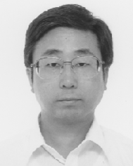 Akihiko Kudo | Akihiko Kudo was born in Tokyo. He received his early education at Tokyo University of Science obtaining a BS degree in 1983 and his PhD degree in 1988 from Tokyo Institute of Technology. After one and half years as a post-doctoral fellow at the University of Texas at Austin he became a Research Associate at the Tokyo Institute of Technology until 1995. He then joined the Tokyo University of Science as a Lecturer before he became Associate Professor in 1998 and Full Professor in 2003. His research interests include photocatalysts for water splitting, electrocatalysis and luminescence materials. |
 Yugo Miseki | Yugo Miseki was born in Tokyo. He received BS and MS degrees from Tokyo University of Science in 2004 and 2006, respectively. He is currently on a doctorate course in Tokyo University of Science under the supervision of Professor Akihiko Kudo. His research interests include the development of novel photocatalysts for water splitting. |
1. Introduction
Energy and environmental issues at a global level are important topics. It is indispensable to construct clean energy systems in order to solve the issues. Hydrogen will play an important role in the system because it is an ultimate clean energy and it can be used in fuel cells. Moreover, hydrogen is used in chemical industries. For example, a large amount of hydrogen is consumed in industrial ammonia synthesis. At present, hydrogen is mainly produced from fossil fuels such as natural gas by steam reforming.| CH4 + H2O → CO + 3H2 | (1) |
| CO + H2O → CO2 + H2 | (2) |
(i) Electrolysis of water using a solar cell, a hydroelectric power generation, etc.
(ii) Reforming of biomass.
(iii) Photocatalytic or photoelectrochemical water splitting (artificial photosynthesis).
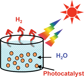
The characteristic point of water splitting using a powdered photocatalyst is the simplicity as shown in Fig. 1. Sun shines at photocatalyst powders dispersed in a pool with water, and then hydrogen is readily obtained. The necessity of separation of H2 evolved from O2 is disadvantageous toward the photocatalytic water splitting process. However, the problem will be able to be overcome using a Z-scheme photocatalyst system. Moreover, powdered photocatalyst systems will be advantageous for large-scale application of solar water splitting because of the simplicity. So, photocatalytic water splitting is an attractive reaction and will contribute to an ultimate green sustainable chemistry and solving energy and environmental issues resulting in bringing an energy revolution.
The photon energy is converted to chemical energy accompanied with a largely positive change in the Gibbs free energy through water splitting as shown in Fig. 2. This reaction is similar to photosynthesis by green plants because these are uphill reactions. Therefore, photocatalytic water splitting is regarded as an artificial photosynthesis and is an attractive and challenging theme in chemistry. From the viewpoint of the Gibbs free energy change, photocatalytic water splitting is distinguished from photocatalytic degradation reactions such as photo-oxidation of organic compounds using oxygen molecules that are generally downhill reactions. This downhill-type reaction is regarded as a photoinduced reaction and has been extensively studied using TiO2 photocatalysts.1,2
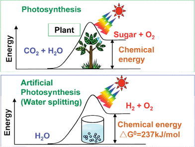 | ||
| Fig. 2 Photosynthesis by green plants and photocatalytic water splitting as an artificial photosynthesis. | ||
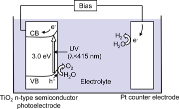
The Honda–Fujishima effect of water splitting using a TiO2 electrode was reported in the early 1970s. When TiO2 is irradiated with UV light electrons and holes are generated as shown in Fig. 3.3 The photogenerated electrons reduce water to form H2 on a Pt counter electrode while holes oxidize water to form O2 on the TiO2 electrode with some external bias by a power supply or pH difference between a catholyte and an anolyte. Numerous researchers had extensively studied water splitting using semiconductor photoelectrodes and photocatalysts since the finding. However, efficient materials for water splitting into H2 and O2 under visible light irradiation had not been found. Accordingly, the photon energy conversion by water splitting using photocatalysts had been considered to be pessimistic, and its research activity had been sluggish. However, new photocatalyst materials for water splitting have recently been discovered one after another. Although the photon energy conversion using powdered photocatalysts is not at the stage of practical use, the research in photocatalytic water splitting is being advanced. The photocatalytic water splitting is still a challenging reaction even if the research history is long.
Many reviews and books for photocatalytic water splitting have been published.4–30 In the present review, we focus on heterogeneous photocatalyst materials of metal oxides, metal (oxy)sulfides and metal (oxy)nitrides for water splitting into H2 and O2 in stoichiometric amount, and H2 or O2 evolution from an aqueous solution containing a sacrificial reagent. After the bases of photocatalytic water splitting are interpreted heterogeneous photocatalyst materials are surveyed. Factors affecting photocatalytic performances and strategies of photocatalyst design are discussed through the general viewpoint. Some applications of newly developed photocatalysts to other photocatalytic reactions such as degradation of organic compounds are also introduced.
2. Bases of photocatalytic water splitting
2.1 Processes in photocatalytic water splitting
Fig. 4 shows the main processes in a photocatalytic reaction.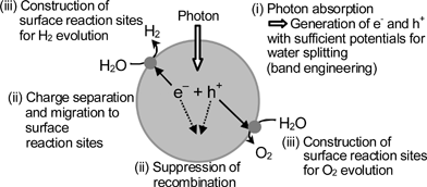 | ||
| Fig. 4 Main processes in photocatalytic water splitting. | ||
The first step (i) is absorption of photons to form electron–hole pairs. Many heterogeneous photocatalysts have semiconductor properties. Photocatalytic reactions proceed on semiconductor materials as schematically shown in Fig. 5. Semiconductors have a band structure in which the conduction band is separated from the valence band by a band gap with a suitable width. When the energy of incident light is larger than that of a band gap, electrons and holes are generated in the conduction and valence bands, respectively. The photogenerated electrons and holes cause redox reactions similarly to electrolysis. Water molecules are reduced by the electrons to form H2 and are oxidized by the holes to form O2 for overall water splitting. Important points in the semiconductor photocatalyst materials are the width of the band gap and levels of the conduction and valence bands. The bottom level of the conduction band has to be more negative than the redox potential of H+/H2 (0 V vs. NHE), while the top level of the valence band be more positive than the redox potential of O2/H2O (1.23 V). Therefore, the theoretical minimum band gap for water splitting is 1.23 eV that corresponds to light of about 1100 nm.
| Band gap (eV) = 1240/λ (nm) | (3) |
| CdS + 2h+→ Cd2+ + S | (4) |
| ZnO + 2h+→ Zn2+ + 1/2O2 | (5) |
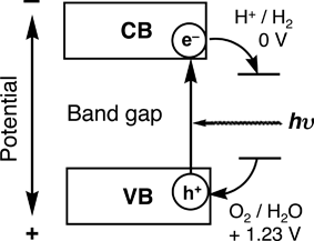 | ||
| Fig. 5 Principle of water splitting using semiconductor photocatalysts. | ||
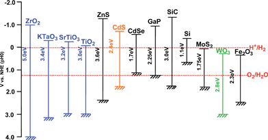 | ||
| Fig. 6 Relationship between band structure of semiconductor and redox potentials of water splitting.5 | ||
The second step (ii) in Fig. 4 consists of charge separation and migration of photogenerated carriers. Crystal structure, crystallinity and particle size strongly affect the step as shown in Fig. 7. The higher the crystalline quality is, the smaller the amount of defects is. The defects operate as trapping and recombination centers between photogenerated electrons and holes, resulting in a decrease in the photocatalytic activity. If the particle size becomes small, the distance that photogenerated electrons and holes have to migrate to reaction sites on the surface becomes short and this results in a decrease in the recombination probability.
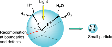 | ||
| Fig. 7 Effects of particle size and boundary on photocatalytic activity. | ||
The final step (iii) in Fig. 4 involves the surface chemical reactions. The important points for this step are surface character (active sites) and quantity (surface area). Even if the photogenerated electrons and holes possess thermodynamically sufficient potentials for water splitting, they will have to recombine with each other if the active sites for redox reactions do not exist on the surface. Co-catalysts such as Pt, NiO and RuO2 are usually loaded to introduce active sites for H2 evolution because the conduction band levels of many oxide photocatalysts are not high enough to reduce water to produce H2 without catalytic assistance. Active sites for 4-electron oxidation of water are required for O2 evolution. Co-catalysts are usually unnecessary for oxide photocatalysts because the valence band is deep enough to oxidize water to form O2 as mentioned in section 7.1.1. This is the characteristic point of heterogeneous photocatalysts being different from homogeneous photocatalysts for which O2 evolution with 4-electron oxidation of H2O is a challenging reaction. Back reactions to form water by reactions between evolved H2, O2, and intermediates easily proceed because of an uphill reaction. Therefore, poor properties for the back reactions are required for the surface of co-catalyst and photocatalyst.
Fig. 8 shows how the processes indicated in Fig. 4 are affected by conditions of a photocatalyst in the case of TiO2. The TiO2 photocatalyst is prepared by several methods. For example, amorphous TiO2 that may be denoted as TiO2·nH2O is obtained by hydrolysis of titanium tetra-isopropoxide. When the amorphous TiO2 is calcined some factors are simultaneously changed. Anatase and rutile are obtained through phase transition. The band gap of anatase is 3.2 eV while that of rutile is 3.0 eV indicating that the crystal structure determines the band gap even if the composition is the same. The difference in the band gap between anatase and rutile is mainly due to the difference in the conduction band level. The conduction band level of anatase is higher than that of rutile leading the difference in photocatalytic abilities between anatase and rutile (brookite TiO2 is selectively prepared by a hydrothermal method).31 Crystallinity is increased by calcination: that is a positive factor as shown in Fig. 7. The crystallinity is confirmed from half-widths of peaks of XRD patterns and also observation by electron microscopes. On the other hand, the surface area (as determined by BET measurement) is decreased with an increase in particle size through sintering: that is a negative factor. Small particle size sometimes gives a quantum size effect as seen in colloidal particles resulting in widening of band gap and blue shift in the absorption spectrum. The resultant photocatalytic activity is dominated by the balance among these factors. A high degree of crystallinity is often required rather than a high surface area for water splitting because recombination between photogenerated electrons and holes is especially a serious problem for uphill reactions. In contrast, high surface area is necessary for photocatalytic degradation of organic compounds because adsorption of the organic compound is the important process. Concentration of surface hydroxyl groups may also affect photocatalytic activity.32
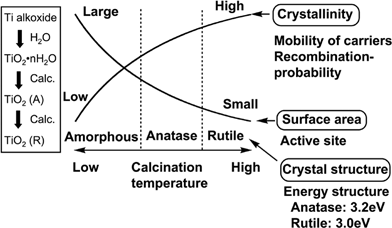 | ||
| Fig. 8 Conditions affecting photocatalytic activity of TiO2. | ||
Many photocatalysts are also materials for solar cells, phosphors and dielectrics. However, the significant difference between the photocatalyst and the other materials is that chemical reactions are involved in the photocatalytic process, but not in the other physical properties. Only when three steps shown in Fig. 4 are simultaneously completed photocatalytic activities can be obtained. Thus, suitable bulk and surface properties, and energy structure are required for photocatalysts. So, it is understandable that photocatalysts should be highly functional materials.
2.2 Photocatalytic H2 or O2 evolution in sacrificial systems
Sacrificial reagents are often employed to evaluate the photocatalytic activity for water splitting as shown in Fig. 9, because overall water splitting is a tough reaction. When the photocatalytic reaction is carried out in an aqueous solution including a reducing reagent, in other words, electron donors or hole scavengers, such as alcohol and a sulfide ion, photogenerated holes irreversibly oxidize the reducing reagent instead of water. It enriches electrons in a photocatalyst and an H2 evolution reaction is enhanced as shown in Fig. 9(a). This reaction will be meaningful for realistic hydrogen production if biomass and abundant compounds in nature and industries are used as the reducing reagents.33–38 On the other hand, photogenerated electrons in the conduction band are consumed by oxidizing reagents (electron acceptors or electron scavengers) such as Ag+ and Fe3+ resulting in that an O2 evolution reaction is enhanced as shown in Fig. 9(b). These reactions using sacrificial reagents are studied to evaluate if a certain photocatalyst satisfies the thermodynamic and kinetic potentials for H2 and O2 evolution. These reactions are regarded as half reactions of water splitting and are often employed as test reactions of photocatalytic H2 or O2 evolution as mentioned in sections 6 and 7. Even if a photocatalyst is active for these half reactions the results do not guarantee a photocatalyst to be active for overall water splitting into H2 and O2 in the absence of sacrificial reagents. From this point, the term of “water splitting” should be distinguishably used for H2 or O2 evolution from aqueous solutions in the presence of sacrificial reagents. Water splitting means to split water into H2 and O2 in a stoichiometric amount in the absence of sacrificial reagents.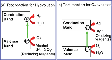 | ||
| Fig. 9 H2 or O2 evolution reaction in the presence of sacrificial reagents—Half reactions of water splitting. | ||
3. Experimental method for water splitting
3.1 Points that should be paid attention
The points that should be paid attention to evaluate photocatalytic water splitting are shown in Fig. 10.7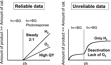 | ||
| Fig. 10 Important points for evaluation of data for photocatalytic water splitting. | ||
 | (6) |
 | (7) |
 | (8) |
The number of reacted electrons is calculated from the amount of evolved H2. The TONs (7) and (8) are smaller than the real TON (6) because the number of atoms is more than that of active sites. Normalization of photocatalytic activity by weight of used photocatalyst (for example, μmol h−1 g−1) is not acceptable because the photocatalytic activity is not usually proportional to the weight of photocatalyst if an amount of photocatalyst is enough for a certain experimental condition. The amount of photocatalyst should be optimized for an each experimental setup. In this case, photocatalytic activity usually depends on the number of photons absorbed by a photocatalyst unless the light intensity is too strong.
 | (9) |
 | (10) |
There are many other points that researchers have to pay attention. The details of experiments for general photocatalysis are described in the literature by Ohtani.40
3.2 Experimental setup
There are several types of apparatus for water splitting. The present authors have usually used a gas-closed circulation system equipped with a vacuum line, a reaction cell and a gas sampling port that is directly connected to a gas chromatograph as shown in Fig. 11. If a photocatalytic activity is too high to use a gas chromatograph a volumetric method is employed for determination of evolved gases. The apparatus should be air-free because the detection of O2 is very important for evaluation of photocatalytic water splitting. There are several reaction cells. In general, efficient irradiation is conducted when an inner irradiation reaction cell is used. A high-pressure mercury lamp is often used with a quartz cell for photocatalysts with wide band gaps when intensive UV light with wavelength shorter than about 300 nm is especially needed. When visible light irradiation is necessary a Xe-lamp with a cut-off filter is usually employed. It is important to know the spectrum of the incident light. It depends on a light source, a material of a reaction cell, an optical filter, a mirror, etc. A solar simulator that is a standard light source for evaluation of solar cells should ideally be used if solar hydrogen production is considered. A solar simulator with an air-mass 1.5 filter (AM-1.5) irradiates 100 mW cm−2 of power.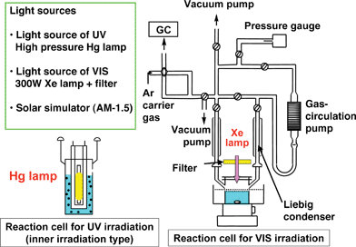 | ||
| Fig. 11 An example of the experimental setup for photocatalytic water splitting. | ||
4. General view of elements constructing heterogeneous photocatalyst materials
Fig. 12 shows elements constructing heterogeneous photocatalyst materials. The elements are classified into four groups; (i) to construct crystal structure and energy structure, (ii) to construct crystal structure but not energy structure, (iii) to form impurity levels as dopants and (iv) to be used as co-catalysts.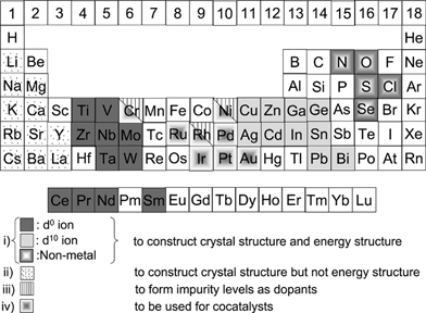 | ||
| Fig. 12 Elements constructing heterogeneous photocatalysts. | ||
Most metal oxide, sulfide and nitride photocatalysts consist of metal cations with d0 and d10 configurations. Their conduction bands for the d0 and d10 metal oxide photocatalysts are usually composed of d and sp orbitals, respectively, while their valence bands consist of O 2p orbitals. Valence bands of metal sulfide and nitride photocatalysts are usually composed of S 3p and N 2p orbitals, respectively. Orbitals of Cu 3d in Cu+, Ag 4d in Ag+, Pb 6s in Pb2+, Bi 6s in Bi3+, and Sn 5s in Sn2+ can also form valence bands in some metal oxide and sulfide photocatalysts as mentioned in sections 7.1.4 and 9.3.
Alkali, alkaline earth and some lanthanide ions do not directly contribute to the band formation and simply construct the crystal structure as A site cations in perovskite compounds.
Some transition metal cations with partially filled d orbitals such as Cr3+, Ni2+ and Rh3+ form some impurity levels in band gaps when they are doped or substituted for native metal cations. Although they often work as recombination centres between photogenerated electrons and holes they sometimes play an important role for visible light response as mentioned in sections 7.1.3 and 9.2.
Some transition metals and the oxides such as noble metals (Pt,41,42 Rh42,43 and Au44,45), NiO46 and RuO247,48 function as co-catalysts for H2 evolution. In water splitting, a back reaction to form water from evolved H2 and O2 has to be suppressed because of an uphill reaction. Au, NiO and RuO2 are suitable co-catalysts on which the back reaction hardly proceeds. A Cr–Rh oxide has recently been found as an excellent co-catalyst for H2 evolution by oxynitride photocatalysts.49,50 IrO2 colloids works as an O2 evolution co-catalyst.51–53
5. Wide band gap metal oxide photocatalysts for water splitting under UV irradiation
5.1 Oxide photocatalysts consisting of d0 metal cations42–43,45,46,54–151
Table 1 shows photocatalyst materials consisting of d0 metal cations (Ti4+, Zr4+, Nb5+, Ta5+ and W6+) for water splitting with reasonable activities. The activities are not directly compared with each other because experimental conditions such as light sources, reaction cells, and the scale of the reaction are different from each other. But the values of activities would make sense as to how high the activities of photocatalysts are.| Photocatalyst | Crystal structure | BG/eV | Co-catalyst | Reactant solution | Activity/μmol h−1 | QY (%) | Ref. (Year) | ||
|---|---|---|---|---|---|---|---|---|---|
| Light sourcea | H2 | O2 | |||||||
| a Hg–Q: combination of 400–450 W Hg lamp with a quartz cell, Hg–P: combination of 400–450 W Hg lamp with a Pyrex cell, Xe–Q: combination of 300–500 W Xe lamp with a quartz cell, Hg–Xe–P: combination of 1000 W Hg–Xe lamp with a Pyrex cell, Hg–Xe–Q: combination of 200 W Hg–Xe lamp with a quartz cell. | |||||||||
| Ti photocatalysts | |||||||||
| TiO2 | Anatase | 3.2 | Rh | Hg–Q | Water vapor | 449 | 29 | 43 (1985) | |
| TiO2 | Anatase | 3.2 | NiOx | Hg–P | 3 M NaOH | 6 | 2 | 54 (1987) | |
| TiO2 | Anatase | 3.2 | Pt | Hg–Q | 2.2 M Na2CO3 | 568 | 287 | 55 (1997) | |
| TiO2 | Anatase | 3.2 | Pt | Hg–Q | Pure water | 106 | 53 | 56 (1995) | |
| B/Ti oxide | Anatase | 3.2 | Pt | Hg–Q | Pure water | 22 | 11 | 57 (1998) | |
| CaTiO3 | Perovskite | 3.5 | NiOx | Hg–Q | 0.2 M NaOH | 30 | 17 | 58 (2002) | |
| SrTiO3 | Perovskite | 3.2 | NiOx | Hg–P | 5 M NaOH | 40 | 19 | 46, 59–63 (1980) | |
| SrTiO3 | Perovskite | 3.2 | Rh | Hg–Xe–P | Pure water | 27 | 14 | 42, 43, 64 (1980) | |
| Sr3Ti2O7 | Layered perovskite | 3.2 | NiOx | Hg–Q | Pure water | 144 | 72 | 65 (2006) | |
| Sr4Ti3O10 | Layered perovskite | 3.2 | NiOx | Hg–Q | Pure water | 170 | 4.5 (at 360 nm) | 66 (2002) | |
| K2La2Ti3O10 | Layered perovskite | 3.4–3.5 | NiOx | Hg–Q | 0.1 M KOH | 2186 | 1131 | 67, 68 (1997) | |
| Rb2La2Ti3O10 | Layered perovskite | 3.4–3.5 | NiOx | Hg–Q | 0.1 M RbOH | 869 | 430 | 5 (at 330 nm) | 67 (1997) |
| Cs2La2Ti3O10 | Layered perovskite | 3.4–3.5 | NiOx | Hg–Q | Pure water | 700 | 340 | 67 (1997) | |
| CsLa2Ti2NbO10 | Layered perovskite | 3.4–3.5 | NiOx | Hg–Q | Pure water | 115 | 50 | 67 (1997) | |
| La2TiO5 | Layered perovskite | NiOx | Hg–Q | Pure water | 442 | 69 (2005) | |||
| La2Ti3O9 | Layered perovskite | NiOx | Hg–Q | Pure water | 386 | 69 (2005) | |||
| La2Ti2O7 | Layered perovskite | 3.8 | NiOx | Hg–Q | Pure water | 441 | 12 (<360 nm) | 69–78 (1999) | |
| La2Ti2O7:Ba | Layered perovskite | NiOx | Hg–Q | Pure water | 5000 | 50 | 69 (2005) | ||
| KaLaZr0.3Ti0.7O4 | Layered perovskite | 3.91 | NiOx | Hg–Q | Pure water | 230 | 116 | 12.5 | 79 (2003) |
| La4CaTi5O17 | Layered perovskite | 3.8 | NiOx | Hg–Q | Pure water | 499 | 20 (<320 nm) | 70 (1999) | |
| KTiNbO5 | Layered structure | 3.6 | NiOx | Hg–Q | Pure water | 30 | 10 | 80 (1999) | |
| Na2Ti6O13 | Tunnel structure | RuO2 | Xe–Q | Pure water | 7.3 | 3.5 | 81–84 (1990) | ||
| BaTi4O9 | Tunnel structure | RuO2 | Xe–Q | Pure water | 33 | 16 | 84–90 (1992) | ||
| Gd2Ti2O7 | Cubic pyrochlore | 3.5 | NiOx | Hg–Q | Pure water | 400 | 198 | 76 (2006) | |
| Y2Ti2O7 | Cubic pyrochlore | 3.5 | NiOx | Hg–Q | Pure water | 850 | 420 | 6 (at 313 nm) | 76, 91, 92 (2004) |
| ZrO2 | 5.0 | None | Hg–Q | Pure water | 72 | 36 | 93–97 (1993) | ||
| Nb photocatalysts | |||||||||
| K4Nb6O17 | Layered structure | 3.4 | NiOx | Hg–Q | Pure water | 1837 | 850 | 5 (at 330 nm) | 45, 98–108 (1986) |
| Rb4Nb6O17 | Layered structure | 3.4 | NiOx | Hg–Q | Pure water | 936 | 451 | 10 (at 330 nm) | 105 (1997) |
| Ca2Nb2O7 | Layered perovskite | 4.3 | NiOx | Hg–Q | Pure water | 101 | 7 (<288 nm) | 70 (1999) | |
| Sr2Nb2O7 | Layered perovskite | 4.0 | NiOx | Hg–Q | Pure water | 217 | 97 | 70, 109–111 (1999) | |
| Ba5Nb4O15 | Layered perovskite | 3.85 | NiOx | Hg–Q | Pure water | 2366 | 1139 | 7 (at 270 nm) | 112 (2006) |
| NaCa2Nb3O10 | Layered perovskite | RuO2 | Hg–Q | Pure water | 118 | 56 | 113 (2005) | ||
| ZnNb2O6 | Columbite | 4.0 | NiOx | Hg–Q | Pure water | 54 | 21 | 114 (1999) | |
| Cs2Nb4O11 | Pyrochlore like | 3.7 | NiOx | Hg–Q | Pure water | 1700 | 800 | 3 (at 270 nm) | 115 (2005) |
| La3NbO7 | Cubic fluorite | 3.9 | NiOx | Hg–Q | Pure water | 35 | 17 | 76, 116 (2004) | |
| Ta photocatalysts | |||||||||
| Ta2O5 | 4.0 | NiOx | Hg–Q | Pure water | 1154 | 529 | 94, 105, 117, 118 (1994) | ||
| K2PrTa5O15 | Tungsten bronze | 3.8 | NiO | Hg–Q | Pure water | 1550 | 830 | 12, 119 (2000) | |
| K3Ta3Si2O13 | Tungsten bronze | 4.1 | NiO | Hg–Q | Pure water | 390 | 200 | 120 (1997) | |
| K3Ta3B2O12 | Tungsten bronze | 4.0 | None | Hg–Q | Pure water | 2390 | 1210 | 6.5 (at 254 nm) | 121 (2006) |
| LiTaO3 | Ilumenite | 4.7 | None | Hg–Q | Pure water | 430 | 220 | 117, 122 (1998) | |
| NaTaO3 | Perovskite | 4.0 | NiO | Hg–Q | Pure water | 2180 | 1100 | 20 (at 270 nm) | 117, 122–124 (1998) |
| KTaO3 | Perovskite | 3.6 | Ni | Hg–Q | Pure water | 6 | 2 | 105, 117, 122 (1996) | |
| AgTaO3 | Perovskite | 3.4 | NiOx | Hg–Q | Pure water | 21 | 10 | 125 (2002) | |
| KTaO3:Zr | Perovskite | 3.6 | NiOx | Xe–Q | Pure water | 9.4 | 4.2 | 126, 127 (1999) | |
| NaTaO3:La | Perovskite | 4.1 | NiO | Hg–Q | Pure water | 19![[thin space (1/6-em)]](https://www.rsc.org/images/entities/char_2009.gif) 800 800 | 9700 | 56 (at 270 nm) | 128, 129 (2000) |
| NaTaO3:Sr | Perovskite | 4.1 | NiO | Hg–Q | Pure water | 9500 | 4700 | 130 (2004) | |
| Na2Ta2O6 | Pyrochlore | 4.6 | NiO | Hg–Q | Pure water | 391 | 195 | 131 (2006) | |
| K2Ta2O6 | Pyrochlore | 4.5 | NiO | Hg–Q | Pure water | 437 | 226 | 131, 132 (2004) | |
| CaTa2O6 | CaTa2O6 (orth.) | 4.0 | NiO | Hg–Q | Pure water | 72 | 32 | 133 (1999) | |
| SrTa2O6 | CaTa2O6 (orth.) | 4.4 | NiO | Hg–Q | Pure water | 960 | 490 | 7 (at 270 nm) | 133 (1999) |
| BaTa2O6 | CaTa2O6 (orth.) | 4.1 | NiO | Hg–Q | Pure water | 629 | 303 | 117, 133 (1998) | |
| NiTa2O6 | 3.7 | None | Hg–Q | Pure water | 11 | 4 | 117 (1998) | ||
| Rb4Ta6O17 | Layered structure | 4.2 | NiO | Hg–Q | Pure water | 92 | 46 | 105 (1996) | |
| Ca2Ta2O7 | Layered perovskite | 4.4 | NiO | Hg–Q | Pure water | 170 | 83 | 131 (2006) | |
| Sr2Ta2O7 | Layered perovskite | 4.6 | NiO | Hg–Q | Pure water | 1000 | 480 | 12 (at 270 nm) | 109–111, 134 (2000) |
| K2SrTa2O7 | Layered perovskite | 3.9 | None | Hg–Q | Pure water | 374 | 192 | 135 (2004) | |
| RbNdTa2O7 | Layered perovskite | 3.9 | NiOx | Hg–Q | Pure water | 117 | 59 | 136–139 (1999) | |
| H2La2/3Ta2O7 | Layered perovskite | 4.0 | NiOx | Hg–Q | Pure water | 940 | 459 | 140 (2005) | |
| K2Sr1.5Ta3O10 | Layered perovskite | 4.1 | RuO2 | Hg–Q | Pure water | 100 | 39.4 | 2 (at 252.5 nm) | 141 (2007) |
| LiCa2Ta3O10 | Layered perovskite | 4.2–4.3 | NiOx | Hg–Q | Pure water | 708 | 333 | 142 (2008) | |
| KBa2Ta3O10 | Layered perovskite | 3.5 | NiOx | Hg–Q | Pure water | 170 | 8 (<350 nm) | 70 (1999) | |
| Sr5Ta4O15 | Layered perovskite | 4.75 | NiO | Hg–Q | Pure water | 1194 | 722 | 134 (2005) | |
| Ba5Ta4O15 | Layered perovskite | NiO | Hg–Q | Pure water | 2080 | 910 | 143 (2005) | ||
| H1.8Sr0.81Bi0.19Ta2O7 | Layered perovskite | 3.88 | None | Hg–Q | Pure water | 250 | 110 | 144 (2008) | |
| Mg–Ta Oxide | Mesoporous | NiO | Hg–Q | Pure water | 102 | 51 | 145 (2004) | ||
| LaTaO4 | Fergusonite | 3.9 | NiOx | Hg–Q | Pure water | 116 | 52 | 146 (2001) | |
| La3TaO7 | Cubic fluorite | 4.6 | NiOx | Hg–Q | Pure water | 164 | 80 | 76, 116 (2004) | |
| Other photocatalysts | |||||||||
| PbWO4 | Scheelite | 3.9 | RuO2 | Hg–Xe–Q | Pure water | 24 | 12 | 147, 148 (2004) | |
| RbWNbO6 | Pyrochlore | 3.6 | NiOx | Hg–Q | 1M RbOH | 11.4 | 4.3 | 149 (2004) | |
| RbWTaO6 | Pyrochlore | 3.8 | NiOx | Hg–Q | 1M RbOH | 69.7 | 34.5 | 149 (2004) | |
| CeO2:Sr | Fluorite | RuO2 | Hg–Q | Pure water | 110 | 55 | 150 (2007) | ||
| BaCeO3 | Perovskite | 3.2 | RuO2 | Hg–Q | Pure water | 59 | 26 | 151 (2008) | |
Valence bands of these photocatalysts, except for AgTaO3, consist of O 2p orbitals of which the potential is about 3 eV vs. NHE while conduction band levels are more negative than 0 eV. It results in that these materials respond to only UV. An Ag 4d orbital forms a valence band of AgTaO3 with a O 2p orbital.125
These metal mixed oxides are usually prepared by a solid-state reaction. Metal oxides and/or alkali and alkaline earth carbonates of starting materials are calcined at high temperature in air.
A polymerizable complex method152 is sometimes used for preparation of photocatalysts.68,74,80,111,112,134,143 This preparation method gives fine and well-crystalline powders with a high surface area at relatively low calcination temperature and short calcination time compared with a conventional solid state method. The example of an Sr2Ta2O7 photocatalyst is shown in Fig. 13.111 SrCO3 and TaCl5 are dissolved in an ethylene glycol (EG) and methanol mixed solution containing anhydrous citric acid (CA) of a chelating agent to stabilize metal cations. The transparent colourless solution is heated at 403 K with stirring to promote polymerization between CA and EG. The solution becomes more viscous with time, and a brown resin-like gel is obtained without any visible precipitation after several hours. The brown gel is heated at 723 K for several hours to remove residual solvents and to burn out unnecessary organics. The powder obtained is referred to as powder precursors for Sr2Ta2O7. The powder precursor is calcined at temperatures between 973 and 1273 K for 5–100 h in air. Some metal oxide photocatalysts that are hardly prepared by solid-state reactions can be obtained by the polymerizable complex method.143 Aqueous processes such as hydrothermal synthesis31,131 are also employed for the preparation of photocatalysts. Photocatalysts prepared by these soft processes sometimes show higher activities than those prepared by solid state reaction because they have small particle size and good crystallinity. Next, let us see each photocatalyst.
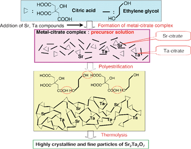 | ||
| Fig. 13 Polymerizable complex method for preparation of Sr2Ta2O7 photocatalyst.111 | ||
SrTiO329,153 and KTaO329,154 photoelectrodes with perovskite structure can split water without an external bias being different from TiO2 because of their high conduction band levels as shown in Fig. 6. These materials can be used as powdered photocatalysts. Domen and co-workers have reported that NiO-loaded SrTiO3 powder can decompose pure water into H2 and O2.46,59–63 The NiO co-catalyst for H2 evolution is usually activated by H2 reduction and subsequent O2 oxidation to form a NiO/Ni double layer structure that is convenient for electron migration from a photocatalyst substrate to a co-catalyst.61 The pretreated NiO co-catalyst is often denoted as NiOx in literature. It is important that the NiO co-catalyst does not cause the back reaction between H2 and O2, being different from Pt. The excellent NiO co-catalyst has often been employed for many photocatalysts for water splitting as seen in Table 1. Rh is also a suitable co-catalyst for the SrTiO3 photocatalyst.42
TiO2 and SrTiO3 photocatalysts are also active for reduction of NO3− using water as an electron donor.155–157
K2La2Ti3O10 that possesses a layered perovskite structure is a unique photocatalyst. H2 evolution proceeds on a pretreated NiOx co-catalyst while O2 evolves at the hydrated interlayer. Many titanate, niobate and tantalate photocatalysts with layered perovskite structure have been reported since the K2La2Ti3O10 photocatalyst was found. Sr3Ti2O7 and Sr4Ti3O10 photocatalysts have perovskite slabs of SrTiO3. La2Ti2O7, La2Ti2O7:Ba, KLaZr0.3Ti0.7O4 and La4CaTi5O17 photocatalysts with layered perovskite structure give high quantum yields.
Na2Ti6O13 and BaTi4O9 with tunnel structure are also unique titanate photocatalysts. KTiNbO5 shows activity when it is prepared by a polymerizable complex method. Gd2Ti2O7 and Y2Ti2O7 with pyrochlore structure are also active.
ZrO2 is active without co-catalyst because of its high conduction band level. This photocatalyst is also active for CO2 reduction to CO accompanied with O2 evolution by oxidation of water without any sacrificial reagents.93
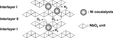 | ||
| Fig. 14 Water splitting over K4Nb6O17 photocatalyst with layered structure.100 | ||
Ca2Nb2O7, Sr2Nb2O7 and Ba5Nb4O15 with layered perovskite structure show high activity. NaCa2Nb3O10 and KCa2Nb3O10 stacked with RuO2 colloids from exfoliated nano-sheets are active for water splitting although the native NaCa2Nb3O10 and KCa2Nb3O10 are active just for half reactions in the presence of sacrificial reagents.113
ZnNb2O6 photocatalyst with d10 and d0 metal ions produce H2 and O2 from pure water.
Ta2O5 shows high activity. K3Ta3Si2O13 and K3Ta3Bi2O12 with pillared structure in which three linear chains of corner-shared TaO6 are connected with each other are active for water splitting without any co-catalyst.120,121 The activity of K3Ta3Si2O13 drastically increased with loading a small amount of a NiO co-catalyst while naked K3Ta3B2O12 shows high activity. Alkali and alkaline earth tantalates show photocatalytic activities for water splitting into H2 and O2. These tantalate photocatalysts are also active for reduction of NO3− to N2 using water as an electron donor.157
Ishihara and co-workers have reported that photocatalytic activity of KTaO3 is improved by doping of Zr, Ti and Hf. Moreover, modification of the KTaO3:Zr photocatalyst by some metal complexes such as vitamin B12 improves the photocatalytic activity through a dye sensitized two-photon process.158 On the other hand, many tantalates with layered perovskite structure are also active. The photocatalytic activity of K2LnTa5O15 with tungsten bronze structure depends on Ln as well as RbLnTa2O7 with layered perovskite structure.119,139
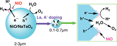
Among tantalates, NiO/NaTaO3 is highly active. The photocatalytic activity of NiO/NaTaO3 increased remarkably with doping of lanthanide ions.128,129 An optimized NiO (0.2 wt%)/NaTaO3:La (2%) photocatalyst shows high activity with an apparent quantum yield of 56% for water splitting. The activity is stable for more than 400 h under irradiation of light from a 400-W high pressure mercury lamp. Bubbles of H2 and O2 evolved can be observed when the photocatalyst is irradiated with UV from a 200 W Xe–Hg lamp as shown in Fig. 15. Only light, water and photocatalyst powder exist in the system. It is amazing that reduction and oxidation of water, completely opposite reactions, simultaneously proceed on the same surface of a nano-particle. The NaTaO3:La photocatalyst is also active for methane coupling.159
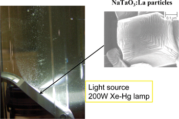 | ||
| Fig. 15 Water splitting using NiO/NaTaO3:La photocatalyst. | ||
A series of A3MO3 (A = Bi, Al, Ga and In, M = Nb and Ta) has been reported.160,161
5.2 Factors affecting photocatalytic ability of d0 metal oxides
Many photocatalysts for water splitting have been found as shown in Table 1. It is important to make such a photocatalyst library because the relationship between the nature of materials and the photocatalytic abilities can be considered. For example, systematic comparison of photocatalytic activities between niobates and tantalates with similar structure give some information on factors that affect photocatalytic ability as mentioned below.| Vfb(NHE) = 2.94 −Eg | (11) |
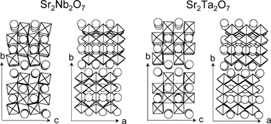 | ||
| Fig. 16 Layered perovskite structures of Sr2M2O7 (M = Nb and Ta).162,163 | ||
The band structures of Sr2Ta2O7 and Sr2Nb2O7 can be roughly described as shown in Fig. 17.109 Band structure of NiO is also shown.165 O2 evolution on Sr2Ta2O7 is as easy as that on Sr2Nb2O7 because the potentials of their valence bands are deep enough to oxidize water into O2. Therefore, it is due to the difference in the conduction band level that the photocatalytic activity of Sr2Ta2O7 is higher than that of Sr2Nb2O7. The high conduction band level causes the driving force for reduction of water to form H2. The reason why Sr2Ta2O7 is able to decompose pure water without co-catalysts is also due to its high conduction band.
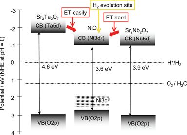 | ||
| Fig. 17 Band structures of Sr2M2O7 (M = Nb and Ta) photocatalysts and NiO co-catalyst.109 | ||
In general, pretreatment of H2 reduction and subsequent O2 oxidation is indispensable for obtaining high activities for NiO-loaded photocatalysts as mentioned in section 5.1.1. The pretreatment is indispensable for NiO/Sr2Nb2O7 as usual whereas it is not for NiO/Sr2Ta2O7. In the case of the nontreated NiO/Sr2Ta2O7 photocatalyst, it is possible that the photogenerated electrons in a conduction band of Sr2Ta2O7 can transfer to a conduction band of NiO because of the suitable potential difference as shown in Fig. 17. In contrast, this appears to be difficult for Sr2Nb2O7 because the potential difference in the conduction band between Sr2Nb2O7 and NiO is negligible. In such a case, pretreatment would be necessary as well as in the case of NiO/SrTiO3. Therefore, the effect of the conduction band level dominates the photocatalytic activities of the Sr2M2O7 system. Systematic investigation of solid solutions also gives some information on factors affecting photocatalytic activities.110,111
In this section, main factors were just discussed from the viewpoint of band structure as shown in Fig. 5. The nature of connection of MO6 octahedra in crystal structure should be suitable for migration of photogenerated electrons and holes, and surface reactions of the carriers with water as indicated by steps (ii) and (iii) in Fig. 4 as mentioned in the next section.
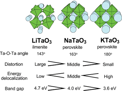 | ||
| Fig. 18 Crystal and energy structures of alkali tantalate photocatalysts.122 | ||
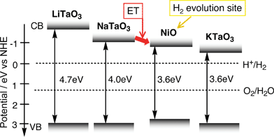 | ||
| Fig. 19 Band structures of alkali tantalate photocatalysts and NiO co-catalyst.122 | ||
Charge separation of photogenerated electrons and holes is required in the case of a water splitting reaction into H2 and O2 more strongly than in the case of photocatalytic reactions in the presence of sacrificial reagents in order to prevent recombination. Sr2Nb2O7 has a dipole moment along perovskite layers, the c axis, due to the distortion of the framework of perovskite layers as shown in Fig. 16. The charge separation may be enhanced by the dipole moment.109 Inoue has proposed the effects of local distortion of polyhedra consisting of the crystal structure of photocatalysts on the charge separation.18 These factors affect charge separation of the step (ii) in Fig. 4.
Time-resolved IR measurements reveal that the La doping prolongs the lifetime of photogenerated electrons in a conduction band or a shallow trap level as shown in Fig. 21.168 The absorption is due to the electrons photogenerated by band gap excitation at 266 nm. The increase in the lifetime is also one of the factors for the improvement of photocatalytic ability. This factor affects the step (ii) in Fig. 4.
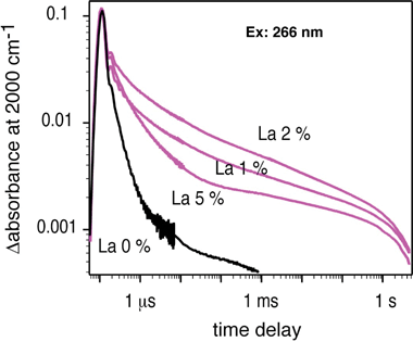 | ||
| Fig. 21 Decay curves of photogenerated electrons in La-doped NaTaO3.168 | ||
5.3 Oxide photocatalysts consisting of d10 metal cations169–180
d10 metal oxides such as ZnO and In2O3 are well-known photocatalysts for a long time. However, they are not active for water splitting because of photocorrosion according to eqn (5) and the low conduction band level, respectively.7 In contrast, Inoue’s group has found various mixed oxide photocatalysts consisting of d10 metal cations, Ga3+, In3+, Ge4+, Sn4+ and Sb5+, for water splitting as shown in Table 2. A RuO2 co-catalyst is indispensable for these photocatalysts except for a Ga2O3 photocatalyst. The RuO2 co-catalyst is loaded using Ru3(CO)12 by an impregnation method. Conduction bands of these photocatalysts consist of sp orbitals of d10 metal cations. These bands are dispersed well resulting in high mobility of photogenerated electrons. Inoue has proposed that the dipole moment formed by distortions of MO4 tetrahedra and MO6 octahedra enhances charge separation of photogenerated carriers.170,176,177 The CaIn2O4 photocatalyst is also used for degradation of Methylene Blue.181–184 Sakata and co-workers have reported a highly efficient Zn-doped β-Ga2O3 photocatalyst with a Ni co-catalyst.180| Photocatalyst | Crystal structure | BGd/eV | Activity/μmol h−1 | Ref. (Year) | |
|---|---|---|---|---|---|
| H2 | O2 | ||||
| a Co-catalyst: RuO2, reactant solution: pure water, light source: 200 W Hg–Xe lamp and a quartz cell.b Co-catalyst: NiO, light source: 450 W Hg lamp equipped in a quartz cell.c Co-catalyst: Ni, light source: 450 W Hg lamp equipped in a quartz cell.d Band gaps not mentioned in papers were determined from DRS. | |||||
| NaInO2 | Layered structure | 3.9 | 0.9 | 0.3 | 169, 170 (2003) |
| CaIn2O4 | Tunnel structure | 21 | 10 | 169–172 (2001) | |
| SrIn2O4 | Tunnel structure | 3.6 | 7 | 3 | 169–173 (2001) |
| LaInO3 | 4.1 | 1 | 0.5 | 172 (2003) | |
| YxIn2−xO3 | 4.3 | 8 | 4 | 174 (2008) | |
| NaSbO3 | Ilmenite | 3.6 | 1.7 | 0.8 | 171, 175 (2001) |
| CaSb2O6 | Layered structure | 3.6 | 1.5 | 0.2 | 175 (2002) |
| Ca2Sb2O7 | Weberite | 3.9 | 3 | 1 | 175 (2002) |
| Sr2Sb2O7 | Weberite | 4.0 | 8 | 3 | 175 (2002) |
| Sr2SnO4 | 5 | 2.5 | 171 (2001) | ||
| ZnGa2O4 | 4.2 | 10 | 4 | 176 (2002) | |
| Zn2GeO4 | Willemite | 4.6 | 22 | 10 | 177 (2004) |
| LiInGeO4 | 4.4 | 26 | 13 | 178 (2005) | |
| Ga2O3b | 4.6 | 46 | 23 | 179 (2004) | |
| Ga2O3:Znc | 4.6 | 4100 | 2200 | 180 (2008) | |
6. Wide band gap metal oxide photocatalysts for H2 or O2 evolution from an aqueous solution containing a sacrificial reagent under UV irradiation185–197
Many metal oxide photocatalysts for water splitting without any sacrificial reagents have been developed as shown in Tables 1 and 2. Therefore, it may appear meaningless to develop wide band gap metal oxide photocatalysts not for water splitting but for H2 or O2 evolution from an aqueous solution containing a sacrificial reagent under UV irradiation. However, their development is still important to get information on factors affecting photocatalytic activity.Table 3 shows wide band gap metal oxide photocatalysts that are active for H2 or O2 evolution from an aqueous solution containing a sacrificial reagent under UV irradiation.
Many layered titanates are active for H2 evolution. H+-exchange often gives higher activity for H2 evolution than the native materials even in the absence of co-catalysts such as Pt. It means that these protonated layered metal oxides possess excellent active sites for H2 evolution. K2Ti4O9 and HCa2Nb3O10 with SiO2 pillars at the interlayer show high activities.188 These layered metal oxides are attractive materials for preparing nano-sheets. Sasaki’s group has extensively studied nano-sheets of layered oxide materials,198 and the term “nano-sheet” was probably first used by Sasaki’s group. Titanate nano-sheets show photocatalytic activity for self-cleaning. Osterloh and co-workers have reported photocatalytic reactions using Pt/HCa2Nb3O10 nano-sheets.199,200
| Photocatalyst | Crystal structure | BG/eV | H2 evolutionb | O2 evolutionc | Ref. (Year) | ||
|---|---|---|---|---|---|---|---|
| Light sourcea | Co-catalyst | Activity/μmol h−1 | Activity/μmol h−1 | ||||
| a Hg–Q: combination of 400–450 W Hg lamp with a quartz cell, Hg–P: combination of 400–450 W Hg lamp with a Pyrex cell, Xe–Q: combination of 300 W Xe lamp with a quartz cell, Xe–P: combination of 300 W Xe lamp with a quartz cell.b Sacrificial reagent: CH3OH aq.c Sacrificial reagent: AgNO3 aq.d ex-Ca2Nb3O10/K+ means that nanosheet was flocculated with K+. | |||||||
| Na2Ti3O7 | Layered structure | Xe–P | Pt | 19 | — | 185 (1987) | |
| K2Ti2O5 | Layered structure | Xe–P | Pt | 34.7 | — | 185 (1987) | |
| K2Ti4O9 | Layered structure | Xe–P | Pt | 4.8 | — | 185 (1987) | |
| Cs2Ti2O5 | Layered structure | 4.4 | Hg–Q | None | 500 | — | 186 (1997) |
| H+-Cs2Ti2O5 | Layered structure | Hg–Q | None | 852 | — | 186 (1997) | |
| Cs2Ti5O11 | Layered structure | 3.75 | Hg–Q | None | 90 | — | 186 (1997) |
| Cs2Ti6O13 | Layered structure | 3.7 | Hg–Q | None | 38 | — | 186 (1997) |
| H+-CsTiNbO5 | Layered structure | 3.0 | Hg–P | Pt | 87 | — | 187 (1990) |
| H+-CsTi2NbO7 | Layered structure | 3.2 | Hg–P | Pt | 320 | — | 187 (1990) |
| SiO2-pillared K2Ti4O9 | Layered structure | 3.17 | Hg–P | Pt | 560 | — | 188 (2000) |
| SiO2-pillared K2Ti2.7Mn0.3O7 | Layered structure | Hg–P | None | 320 | — | 188 (2000) | |
| Na2W4O13 | Layered structure | 3.1 | Hg–P | Pt | 21 | 9 | 189 (1997) |
| H+-KLaNb2O7 | Layered perovskite | Hg–Q | Pt | 3800 | 46 | 8 (2000) | |
| H+-RbLaNb2O7 | Layered perovskite | Hg–Q | Pt | 2600 | 2 | 8 (2000) | |
| H+-CsLaNb2O7 | Layered perovskite | Hg–Q | Pt | 2200 | 3 | 8 (2000) | |
| H+-KCa2Nb3O10 | Layered perovskite | Hg–Q | Pt | 19![[thin space (1/6-em)]](https://www.rsc.org/images/entities/char_2009.gif) 000 000 | 8 | 8 (2000) | |
| SiO2-pillared KCa2Nb3O10 | Layered perovskite | Hg–P | Pt | 10![[thin space (1/6-em)]](https://www.rsc.org/images/entities/char_2009.gif) 800 800 | 190, 191 (1993) | ||
| ex-Ca2Nb3O10/K+ nanosheet4) | Layered perovskite | Xe–P | Pt | 550 | 192 (2002) | ||
| Restacked ex-Ca2Nb3O10/Na+ | Layered perovskite | Xe–P | Pt | 880 | 192 (2002) | ||
| H+-RbCa2Nb3O10 | Layered perovskite | Hg–Q | Pt | 17![[thin space (1/6-em)]](https://www.rsc.org/images/entities/char_2009.gif) 000 000 | 16 | 8 (2000) | |
| H+-CsCa2Nb3O10 | Layered perovskite | Hg–Q | Pt | 8300 | 10 | 8 (2000) | |
| H+-KSr2Nb3O10 | Layered perovskite | Hg–Q | Pt | 43![[thin space (1/6-em)]](https://www.rsc.org/images/entities/char_2009.gif) 000 000 | 30 | 8 (2000) | |
| H+-KCa2NaNb4O13 | Layered perovskite | Hg–Q | Pt | 18![[thin space (1/6-em)]](https://www.rsc.org/images/entities/char_2009.gif) 000 000 | 39 | 8 (2000) | |
| Bi2W2O9 | Aurivillius like | 3.0 | Hg–P | Pt | 18 | 281 | 193 (1999) |
| Bi2Mo2O9 | Aurivillius like | 3.1 | Xe–P | — | — | 1.8 | 193 (1999) |
| Bi4Ti3O12 | Aurivillius | 3.1 | Hg–P | Pt | 0.6 | 3 | 193 (1999) |
| BaBi4Ti4O15 | Aurivillius | 3.1 | Hg–P | Pt | 8.2 | 3.7 | 193 (1999) |
| Bi3TiNbO9 | Aurivillius | 3.1 | Hg–P | Pt | 33 | 31 | 193 (1999) |
| PbMoO4 | Scheelite | 3.31 | Xe–P | Pt | 1.9 | 12.8 | 194 (1990) |
| (NaBi)0.5MoO4 | Scheelite | 3.1 | Xe–P | Pt | 0.6 | 58 | 195 (2004) |
| (AgBi)0.5MoO4 | Scheelite | 3.0 | Xe–P | Pt | 0 | 10.7 | 195 (2004) |
| (NaBi)0.5WO4 | Scheelite | 3.5 | Xe–P | Pt | 7 | 1.3 | 195 (2004) |
| (AgBi)0.5WO4 | Scheelite | 3.5 | Xe–P | Pt | 0.1 | 5.8 | 195 (2004) |
| Ga1.14In0.86O3 | 3.7 | Hg–P | Pt | 30 | 30 | 196 (1998) | |
| β–Ga2O3 | 4.6 | Xe–Q | Pt | 50 | 7 | 196 (1998) | |
| Ti1.5Zr1.5(PO4)4 | 3.8 | Xe–Q | Pt | 11.8 | — | 197 (2005) | |
Bi2W2O9, BaBi4Ti4O15 and Bi3TiNbO9 consisting of a layered structure with perovskite slabs are active not only for O2 but also H2 evolution in the presence of sacrificial reagent. Na2W4O13 photocatalyst with layered structure is also active for H2 or O2 evolution from aqueous solutions in the presence of sacrificial reagents although WO3 is inactive for H2 evolution. Homogeneous photocatalysts of tungsten-polyacids are also active for H2 evolution.201
PbMoO4 with scheelite structure shows activities for H2 and O2 evolution in the presence of sacrificial reagents under UV irradiation. The substituted compounds, Na0.5Bi0.5MoO4, Ag0.5Bi0.5MoO4, Na0.5Bi0.5WO4 and Ag0.5Bi0.5WO4, are also active for O2 evolution. In these photocatalysts, although these molybdates and tungstates respond to only UV, Pb, Bi and Ag play an important role for making the valence bands as mentioned in section 7.1.4.
Solid solutions of β-Ga2O3 and In2O3 consisting of d10 cations have been systematically studied for photocatalytic activities for H2 or O2 evolution from aqueous solutions in the presence of sacrificial reagents.196 In this photocatalyst system, the band gap and luminescent energy decrease as the ratio of indium increases.
7. Photocatalysts with visible light response for H2 or O2 evolution from an aqueous solution containing a sacrificial reagent
Development of photocatalysts that work only for half reactions of water splitting in the presence of sacrificial reagents might seem meaningless but this view is incorrect. These photocatalysts can be used to construct Z-scheme systems that are active for water splitting under visible light irradiation as mentioned in section 8.3. Moreover, some of them will be able to produce H2 using biomass and abundant compounds.33–38Tables 4 and 5 list photocatalysts for H2 or O2 evolution from aqueous solutions containing sacrificial reagents under visible light irradiation.| Photocatalyst | BG (EG)/eV | Activity/μmol h−1 | Ref. (Year) | ||
|---|---|---|---|---|---|
| Light sourcea | H2b | O2c | |||
| a Xe–L42: 300–500 W Xe lamp with a cut-off filter (L42), Hg–L42: 500 W lamp with a cut-off filter (L42), Xe–L44: 300 W Xe lamp with a cut-off filter (L44), W–L42: 450 W lamp with a cut-off filter (L42).b Co-catalyst: Pt, sacrificial reagent: CH3OH aq.c Sacrificial reagent: AgNO3 aq.d Co-catalyst: IrO2. | |||||
| WO3 | 2.8 | Xe–L42 | — | 65 | 4, 5, 202–204 (1962) |
| Bi2WO6 | 2.8 | Xe–L42 | — | 3 | 193 (1999) |
| Bi2MoO6 | 2.7 | Xe–L42 | — | 55 | 205 (2006) |
| Bi2Mo3O12 | 2.88 | Xe–L42 | — | 8 | 205 (2006) |
| Zn3V2O8 | 2.92 | Xe–L42 | — | 10.2 | 206 (2005) |
| Na0.5Bi1.5VMoO8 | 2.5 | Xe–L42 | — | 74 | 207 (2008) |
| In2O3(ZnO)3 | 2.6 | Xe–L42 | 1.1 | 1.3 | 208 (1998) |
| SrTiO3:Cr/Sb | 2.4 | Xe–L42 | 78 | 0.9 | 209 (2002) |
| SrTiO3:Ni/Ta | 2.8 | Xe–L42 | 2.4 | 0.5 | 210 (2005) |
| SrTiO3:Cr/Ta | 2.3 | Xe–L42 | 70 | — | 211 (2004) |
| SrTiO3:Rh | 2.3 | Xe–L42 | 117 | 0 | 212 (2004) |
| CaTiO3:Rh | Xe–L42 | 8.5 | 0 | 213 (2006) | |
| La2Ti2O7:Cr | 2.2 | Hg–L42 | 15 | — | 214, 215 (2004) |
| La2Ti2O7:Fe | 2.6 | Hg–L42 | 10 | — | 214, 215 (2004) |
| TiO2:Cr/Sb | 2.2 | Xe–L42 | 0.06 | 31.5 | 209 (2002) |
| TiO2:Ni/Nb | 2.6 | Xe–L44 | 0 | 7.6 | 210 (2005) |
| TiO2:Rh/Sb | 2.13 | Xe–L44 | — | 16.9 | 216 (2007) |
| PbMoO4:Cr | 2.26 | Xe–L42 | — | 71.5 | 217 (2007) |
| RbPb2Nb3O10 | 2.5 | Xe–L42 | 4 | 1.1 | 218 (1993) |
| PbBi2Nb2O9 | 2.88 | W–L42 | 3.2 | 520 | 219, 220 (2004) |
| BiVO4 | 2.4 | Xe–L42 | — | 421 | 221–224 (1998) |
| BiCu2VO6 | 2.1 | Xe–L42 | — | 2.3 | 225 (2005) |
| BiZn2VO6 | 2.4 | Xe–L42 | — | 6 | 226 (2006) |
| SnNb2O6 | 2.3 | Xe–L42 | 14.4 | 62.8d | 227–229 (2004) |
| AgNbO3 | 2.86 | Xe–L42 | 8.2 | 37 | 125 (2002) |
| Ag3VO4 | 2.0 | Xe–L42 | — | 17 | 230 (2003) |
| AgLi1/3Ti2/3O2 | 2.7 | Xe–L42 | — | 24 | 231 (2008) |
| AgLi1/3Sn2/3O2 | 2.7 | Xe–L42 | — | 53 | 231 (2008) |
| Photocatalyst | Sensitizer | Sacrificial reagent | Light source | Incident light/nm | H2 evolution/μmol h−1 | Ref. (Year) |
|---|---|---|---|---|---|---|
| a Turnover number. | ||||||
| TiO2 | Ru(bpy)32+ | Water–MeOH vapor | 500 W Xe | >440 | 0.9 | 270, 271 (1982) |
| Pt/ZnO | Erythrosine | Triethanolamine + I− | 500 W Xe | >420 | 80.4 | 272 (1985) |
| H2K2Nb6O17 | Ru(bpy)32+ | I− | 500 W Hg–Xe | >400 | 0.4 | 273 (1993) |
| Pt/TiO2 | Zn-porphyrin | EDTA | 1000 W Xe | >520 | 182 (9h)a | 274 (1995) |
| Pt/TiO2 | NK-2405 | Acetonitrile + I | 300 W Xe | >410 | 210 | 275, 276 (2003) |
| Pt/TiO2 | C-343 | Acetonitrile + I | 300 W Xe | >410 | 156 | 275, 276 (2003) |
| Pt(in)/H4Nb6O17 | NK-2405 | Acetonitrile + I | 300 W Xe | >410 | 94 | 275, 276 (2003) |
| Ni/K4Nb6O17 | CdS | K2SO3 | 300 W Xe | >420 | 56 | 277, 278 (1988) |
| H4Nb6O17 | CdS | Na2S | 100 W Hg | >400 | 220 | 279 (2001) |
| H2Ti4O9 | CdS | Na2S | 100 W Hg | >400 | 560 | 279 (2001) |
7.1 Oxide photocatalysts4–5,125,193,202–231
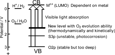 | ||
| Fig. 22 Band structure control to develop visible light-driven-photocatalysts for water splitting. | ||
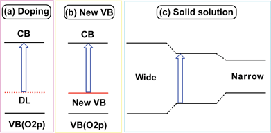 | ||
| Fig. 23 Strategies of band engineering for design of visible-light-driven photocatalysts. | ||
Oxide photocatalysts for H2 or O2 evolution from aqueous solutions in the presence of sacrificial reagents under visible light irradiation are summarized in Table 4.
Bi2WO6 and Bi2MoO6 with the Aurivillius structure are active for an O2 evolution reaction under visible light irradiation. These tungstate and molybdate photocatalysts are not active for H2 evolution because of the low conduction band level. These photocatalysts are also used for degradation of HCHO,233 CH3OH,234 CH3COOH,235,236 Rhodamine B237–249 and Methylene Blue.240,244,247
Co-doping of Cr3+/Ta5+, Cr3+/Sb5+, Ni2+/Ta5+ and doping of Rh cations is effective in sensitization of SrTiO3 to visible light. These doped SrTiO3 powders with Pt co-catalysts show photocatalytic activities for H2 evolution from aqueous methanol solutions under visible light irradiation. Cr and Fe are effective dopants for H2 evolution over a La2Ti2O7 photocatalyst. Rh-doped SrTiO3 is one of the rare oxide photocatalysts that can efficiently produce H2 under visible light irradiation. This Rh doping is also effective for CaTiO3. The SrTiO3:Rh photocatalyst plays an important role on a Z-scheme photocatalyst system for water splitting under visible light irradiation as mentioned in section 8.3. On the other hand, TiO2 (rutile) co-doped with Cr3+/Sb5+, Rh3+/Sb5+ and Ni2+/Nb5+ is active for O2 evolution from aqueous silver nitrate solutions. In these doped photocatalysts, the dopants form electron donor levels in the band gap of the TiO2 and SrTiO3 host materials, resulting in visible light response. When Ti4+ is replaced with Cr3+ or Ni2+, the charge becomes unbalanced. This may result in the formation of recombination centres. Co-doped metal cations such as Nb5+, Ta5+ and Sb5+ compensate the charge imbalance, resulting in the suppression of the formation of the recombination centres and maintaining the property of visible light absorption. When about 1% of Cr was doped into TiO2 without any co-dopant, activities were never obtained as a rule. Thus, transition metal doping into photocatalysts with wide band gaps is effective for the development of visible light responsive photocatalysts if a suitable combination of dopant–co-dopant is chosen. Next, the co-doping effect is discussed using the TiO2:Rh/Sb and TiO2:Cr/Sb photocatalysts in more detail.
Fig. 24 shows dependence of photocatalytic O2 evolution from an aqueous silver nitrate solution on TiO2:Rh/Sb upon the ratio of doped Sb to Rh.216 When only Rh is doped into TiO2 no activity is obtained and the colour of the photocatalyst is black. When the ratio of Sb/Rh is equal to or larger than the unity O2 evolution activity is observed accompanied with a colour change from black to orange. TiO2:Rh without co-doping of Sb contains Rh4+ because Rh is doped at a Ti4+ site. The Rh4+ species predominantly works as a recombination site. As the ratio of co-doped Sb increases, the formation of Rh4+ is suppressed. Co-doping with Sb5+ produces Rh3+ forming an electron donor level, due to keeping of the charge balance, and results in showing of photocatalytic activities. The same dependency is observed for a TiO2:Cr/Sb photocatalyst in which formation of Cr6+ is suppressed by the Sb5+ co-doping.209 It is confirmed by IR transient absorption spectroscopy for the TiO2:Cr/Sb photocatalyst that the Sb5+ co-doping prolongs a lifetime of photogenerated electrons as shown in Fig. 25.251 TiO2:Cr/Sb with 1.0–2.0 of optimum ratios gives slowest decay when it is excited by 532 nm. It is interesting that the lifetime of photogenerated electrons for the optimized TiO2:Cr/Sb is longer than that for nondoped TiO2 even by the band gap excitation. The decay is too fast to measure in this time scale by pumping of both wavelengths for inactive TiO2:Cr/Sb with smaller ratios than unity. The visible light responses are due to the transitions from electron donor levels consisting of Rh3+ and Cr3+ to the conduction band of the TiO2 host. The TiO2:Rh/Sb and TiO2:Cr/Sb photocatalysts can use visible light up to 600 nm, of relatively long wavelength for O2 evolution photocatalysts.
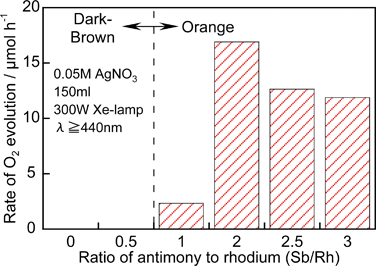 | ||
| Fig. 24 Effect of co-doping of Sb to TiO2:Rh (1.3%) on photocatalytic activity under visible light irradiation.216 | ||
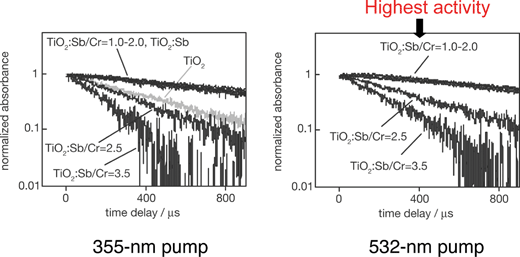 | ||
| Fig. 25 Decay curves of photogenerated electrons in TiO2:Sb/Cr photocatalyst.251 | ||
PbMoO4 shows activities for H2 and O2 evolution in the presence of sacrificial reagents under UV irradiation as shown in Table 3. When Cr6+ is partly replaced for Mo6+ in this host material Cr6+ forms an electron acceptor level resulting in a visible light response.217 DFT calculation revealed that this visible light response is due to the transition from the valence band consisting of Pb 6s and O 2p to the electron acceptor level composed of Cr 3d empty orbitals. Formation of such an acceptor level is also useful for sensitization of wide band gap photocatalysts to visible light if the potential for H2 evolution is not required.
Anion doping such as nitrogen to a TiO2 photocatalyst has been studied for oxidation of organic compounds.250
Orbitals of Pb 6s in Pb2+, Bi 6s in Bi3+, Sn 5s in Sn2+ and Ag 4d in Ag+ can form valence bands above the valence band consisting of O 2p orbitals in metal oxide photocatalysts. The degree of the contribution of these metal cations to the valence band formation depends on the crystal structure and the ratio of the metal cations contained.
RbPb2Nb3O10 and PbBi2Nb2O9 with layered perovskite structure show activity for H2 or O2 evolution.
BiVO4 with a monoclinic scheelite structure shows photocatalytic activities for O2 evolution from aqueous silver nitrate solutions under visible light irradiation. BiVO4 can be prepared by an aqueous process at ambient temperature and pressure222,223 in an environmentally friendly process. The photocatalytic activity of BiVO4 prepared by the aqueous process is much higher than that of BiVO4 prepared by a conventional solid state reaction. The difference in the photocatalytic activity between BiVO4 obtained by the different methods is due to the crystallinity and defects. The aqueous process is especially advantageous for the preparation of materials in which defects are easily formed by volatilization at high temperature calcination. The valence band formation by Bi 6s orbitals is confirmed by the band structure and density of states obtained by DFT calculation as shown in Fig. 26. The conduction band is composed of V 3d as in other d0 oxide photocatalysts. Although BiVO4 does not show activity for H2 evolution due to the low conduction level, it is noteworthy that the valence band formed with Bi 6s orbitals possesses the potential for water oxidation to form O2 accompanied by 4-electron oxidation. BiVO4 is also used for the decomposition of endocrine disruptors such as nonylphenol252 and degradation of Methylene Blue,253,254 Methyl Orange,255–258 Rhodamine B,259,260 4-n-alkylphenol,261,262 4-n-nonylphenol,261,262 aromatic hydrocarbons,263 and benzopyrene.264 OH radicals that are often an active species for photocatalytic oxidation of organic compounds are not involved with the degradation in the case of the BiVO4 photocatalyst.265
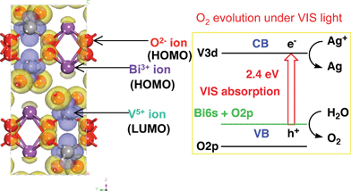 | ||
| Fig. 26 Band structure of BiVO4 calculated by DFT. | ||
SnNb2O6 shows activity for H2 or O2 evolution when suitable co-catalysts are loaded. Especially, IrO2/SnNb2O6 shows relatively high activity for O2 evolution.229 Although SnNb2O6 is active for half reactions of water splitting under visible light irradiation overall water splitting is as yet not successful. Sn 5s orbitals in Sn2+ form a valence band as seen in SnNb2O6 while Sn 5s5p orbitals in Sn4+ form a conduction band as observed for Sr2SnO4 (Table 2).
AgNbO3 with a perovskite structure and Ag3VO4 are active for O2 evolution. AgLi1/3Ti2/3O2 and AgLi1/3Sn2/3O2 with delafossite structure are synthesized by treating layered compounds Li2TiO3 and Li2SnO3 with molten AgNO3 through ion exchange of Li+ for Ag+ and show activities for O2 evolution from an aqueous silver nitrate solution under visible light irradiation. The visible light responses of AgNbO3, AgLi1/3Ti2/3O2 and AgLi1/3Sn2/3O2 are due to the band gap excitation between conduction bands consisting of either Nb 4d or Ti 3d or Sn 5s5p orbitals and valence bands consisting of Ag 4d orbitals.125,231 AgNbO3 is also active for the decomposition of endocrine disruptors such as nonylphenol.266 Moreover, band engineering using the Ag 4d orbital is applied to develop solid solution photocatalysts of AgNbO3–SrTiO3 for degradations of 2-propanol267,268 and CH3CHO.269
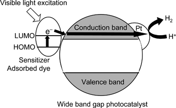 | ||
| Fig. 27 Scheme of sensitized-type photocatalyst. | ||
7.2 (Oxy)nitride and oxysulfide photocatalysts281–296
Domen and co-workers have reported (oxy)nitrides and oxysulfides as new types of visible light-driven photocatalysts as shown in Table 6. The valence bands of these photocatalysts consist of N 2p and S 3p orbitals, in addition to O 2p, resulting in the formation of narrow band gaps. These materials can utilize up to 500–600 nm visible light.| Photocatalyst | BG/eV | H2 evolutionb | O2 evolutionc | Ref. (Year) | ||||
|---|---|---|---|---|---|---|---|---|
| Co-catal. | Activity/μmol h−1 | QY (%) | Co-catal. | Activity/μmol h−1 | QY (%) | |||
| a Light source: 300 W Xe lamp with a cut-off filter (L42).b Sacrificial reagent: CH3OH aq.c Sacrificial reagent: AgNO3 aq. La2O3 or La(NO)3 was added as a buffer for pH. | ||||||||
| LaTiO2N | 2.1 | Pt | 30 | 0.15 | IrO2 | 41 | 1.5 | 281 (2002) |
| Ca0.25La0.75TiO2.25N0.75 | 2.0 | Pt | 5.5 | IrO2 | 230 | 5 | 281 (2002) | |
| TaON | 2.5 | Ru | 120 | 0.2 | 380 | 34 | 282–286 (2002) | |
| Ta3N5 | 2.1 | Pt | 10 | 0.1 (420–600 nm) | 420 | 10 (420–600 nm) | 284, 286–288 (2002) | |
| CaNbO2N | 1.9 | Pt | 1.5 | — | 46 | — | 289 (2002) | |
| CaTaO2N | 2.5 | Pt | 15 | — | 0 | — | 290 (2004) | |
| SrTaO2N | 2.1 | Pt | 20 | — | 0 | — | 290 (2004) | |
| BaTaO2N | 2.0 | Pt | 15 | — | 0 | — | 290 (2004) | |
| LaTaO2N | 2.0 | Pt | 20 | — | 0 | — | 289 (2002) | |
| Y2Ta2O5N2 | 2.2 | Pt-Ru | 250 | — | 140 | — | 291 (2004) | |
| TiNxOyFz | 2.2 | — | — | — | 30 | — | 292, 293 (2003) | |
| Sm2Ti2O5S2 | 2.0 | Pt | 22 | 0.3 | 30 | 0.6 | 53, 294, 295(2002) | |
| La–In oxisulfide | 2.6 | Pt | 10 | 0.2 | IrO2 | 7 | 0.1 | 296 (2007) |
Oxynitride photocatalysts consisting of metal cations of Ti4+, Nb5+ and Ta5+ with d0 configuration are active for H2 or O2 evolution in the presence of sacrificial reagents. TaON and Ta3N5 give high quantum yields for O2 evolution. However, they are not active for water splitting into H2 and O2 without sacrificial reagents at the present stage. These materials can also be applied to photoelectrochemical cells.297–299 Although metal sulfides such as CdS cannot evolve O2 because of photocorrosion, Sm2Ti2O5S2, an oxysulfide with layered perovskite structure is active for the O2 evolution.
8. Photocatalyst systems for water splitting under visible light irradiation
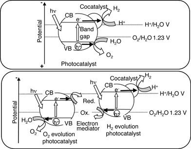
There are two types of photocatalyst systems for water splitting under visible light irradiation as shown in Fig. 28. Band engineering is indispensable to develop the single photocatalyst system as shown in Fig. 22. Some oxynitride photocatalysts are active for water splitting as mentioned in the next section. Two-photon systems, as seen in photosynthesis by green plants (Z-scheme), is another way to achieve overall water splitting as mentioned in section 8.3. The Z-scheme is composed of an H2-evolution photocatalyst, an O2-evolution photocatalyst, and an electron mediator. Photocatalysts that are active only for half reactions of water splitting as shown in Fig. 9 can be employed for the construction of the Z scheme: that is the merit of the Z scheme. Some photocatalysts listed in Table 4 are actually used for Z-scheme systems.8.1 d10 metal nitrides300–312
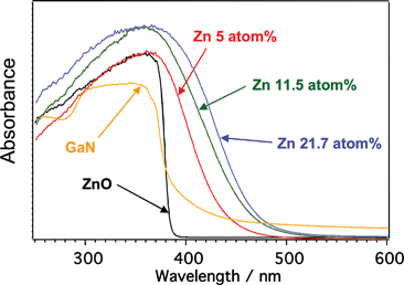
Nitrides consisting of d10 metal cations are active for water splitting as shown in Table 7, in contrast to d0 metal (oxy)nitrides. Ge3N4 shows activity under UV irradiation. This is the first example of a non-oxide powdered photocatalyst for water splitting.300 GaN is the well known semiconductor that is used for a blue light emitting diode.313 Native GaN powder is not active whereas GaN loaded with Rh2−xCrxO3 co-catalyst and Mg-doped GaN powders are active under UV irradiation. In contrast, GaN:ZnO solid solutions are active under visible light irradiation. The solid solutions are prepared by NH3-treatment of a mixture of Ga2O3 and ZnO at 1123–1223 K for 5–30 h. Although native GaN and ZnO possess only UV absorption bands, the solid solutions have visible light absorption bands depending on the composition as shown in Fig. 29.307 The visible light absorption is due to a Zn-related acceptor level and/or p–d repulsion between Zn 3d and N 2p + O 2p in addition to the contribution of N 2p to valence band formation.312,314,315 Optimized GaN:ZnO with Rh2−xCrxO3 co-catalyst gives 5.9% of quantum yield.311 Ge3N4:ZnO is also active under visible light irradiation.| Photocatalyst | BG/eV | Co-catalyst | Incident light/nm | Reactant solution | Activity/μmol h−1 | QY (%) | Ref. (Year) | |
|---|---|---|---|---|---|---|---|---|
| H2 | O2 | |||||||
| a Light source: 450 W high pressure mercury lamp, reaction cell: inner irradiation cell.b Made of quartz.c Made of Pyrex.d Made of Pyrex filled with aqueous NaNO2 solution as a filter. | ||||||||
| Ge3N4 | 3.6 | RuO2 | >200b | Pure water | 1400 | 700 | 9 (at 300 nm) | 300–303 (2005) |
| GaN | 3.4 | Rh2−xCrxO3 | >300c | H2SO4 (pH 4.5) | 19 | 9.5 | 0.7 (300–340 nm) | 304 (2007) |
| GaN:Mg | 3.4 | RuO2 | >300c | Pure water | 730 | 290 | 305, 306 (2006) | |
| (Ga0.88Zn0.12)(N0.88O0.12) | 2.6 | Rh2−xCrxO3 | >400d | H2SO4 (pH 4.5) | 800 | 400 | 5.9 (420–440 nm) | 50, 307–311 (2005) |
| Zn1.44GeN2.08O0.38 | 2.7 | RuO2 | >400d | Pure water | 14.2 | 7.4 | 312 (2007) | |
8.2 d0 metal oxides
InTaO4316,317 and YBiWO6318 have been reported for water splitting as single photocatalyst systems under visible light irradiation.8.3 Z-Scheme systems (two-photon process)319–325
Table 8 summarizes Z-scheme systems that work under visible light irradiation. Combined systems with Fe ion-WO3,326 Pt/TiO2(anatase)–TiO2(rutile)–IO3−/I−321,327 and Pt/TiO2(anatase)–Pt/WO3–IO3−/I−321 are active for water splitting through a two-photon process under UV irradiation because an iron ion and TiO2 respond to only UV. Combined systems with Pt/SrTiO3:Cr/Ta for the H2 evolution photocatalyst and Pt/WO3 for the O2 evolution photocatalyst can split water into H2 and O2 in stoichiometric amounts under visible light irradiation in the presence of an IO3−/I− redox couple. Oxynitride photocatalysts, TaON, CaTa2O2N and BaTa2O2N can be used as H2 evolution photocatalysts with a Pt/WO3 of O2 evolution photocatalyst. These photocatalyst systems respond to about 450-nm light, which is limited by the band gap of WO3. The system of Pt/TaON with RuO2/TaON is a unique combination and is active up to 500 nm. The Z-scheme system consisting of Pt/SrTiO3:Rh and BiVO4 or Bi2MoO6 is also active in the presence of an Fe3+/Fe2+ redox couple. The system of Pt/SrTiO3:Rh and BiVO4 responds to 520-nm light, which corresponds to the energy and band gaps of SrTiO3:Rh and BiVO4 as shown in Fig. 30. Although the efficiency is low, solar hydrogen production from water has been accomplished using the Z-scheme system with powdered photocatalysts as shown in Fig. 31. It is a simple system: the sun is allowed to shine on the powders dispersed in aqueous solutions of iron ions and Co complexes which causes water splitting to form H2 and O2.| H2 photocatalyst | O2 photocatalyst | Mediator | Activity/μmol h−1 | QY (%) | Ref. (Year) | |
|---|---|---|---|---|---|---|
| H2 | O2 | |||||
| a Light source: 300 W Xe lamp with a cut-off filter (L42). | ||||||
| Pt/SrTiO3:Cr,Ta | Pt/WO3 | IO3−/I− | 16 | 8 | 1 (at 420 nm) | 319–321 (2001) |
| Pt/TaON | RuO2/TaON | IO3−/I− | 3 | 1.5 | 0.1–0.2 | 322 (2008) |
| Pt/CaTaO2N | Pt/WO3 | IO3−/I− | 6.6 | 3.3 | — | 323 (2008) |
| Pt/BaTaO2N | Pt/WO3 | IO3−/I− | 4 | 2 | — | 323 (2008) |
| Pt/TaON | Pt/WO3 | IO3−/I− | 24 | 12 | 0.4 (at 420 nm) | 324 (2005) |
| Pt/SrTiO3:Rh | BiVO4 | Fe3+/2+ | 15 | 7.2 | 0.3 (at 440 nm) | 325 (2004) |
| Pt/SrTiO3:Rh | Bi2MoO6 | Fe3+/2+ | 19 | 8.9 | 0.2 (at 440 nm) | 325 (2004) |
| Pt/SrTiO3:Rh | WO3 | Fe3+/2+ | 7.8 | 4.0 | 0.2 (at 440 nm) | 325 (2004) |
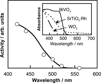 | ||
| Fig. 30 Action spectrum for water splitting using (Ru/SrTiO3:Rh)–(BVO4)–FeCl3.325 | ||
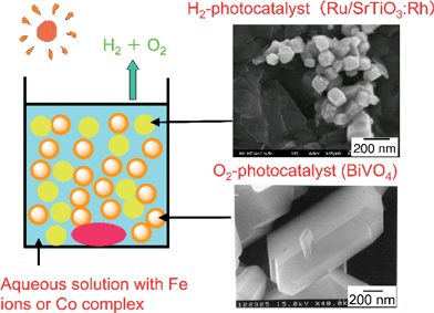 | ||
| Fig. 31 Solar water splitting by Z-scheme photocatalyst system with nano-oxides. | ||
9. Metal sulfide photocatalysts with visible light response for H2 evolution from an aqueous solution containing a sacrificial reagent328–349
Metal sulfides are attractive materials as candidates of visible-light-driven photocatalysts. The valence band usually consists of S 3p orbitals the level of which is more negative than O 2p as shown in Fig. 22. Although instability is a drawback of metal sulfide photocatalysts the photocorrosion is suppressed by hole scavenger such as S2− and SO32−.Many metal sulfide photocatalysts have been reported for H2 evolution in the presence of sacrificial reagents as shown in Table 9.
| Photocatalyst | BG/eV | Incident light/nm | Light source | Reactant solution | H2 evolution/μmol h−1 | QY (%) | Ref. (Year) |
|---|---|---|---|---|---|---|---|
| Pt/CdS | 2.4 | >390 | 500 W Hg | Na2SO3 | 40 | 35 (at 436 nm) | 328–331 (1983) |
| ZnS | 3.1 | >200 | 200 W Hg | Na2S + H3PO2 + NaOH | 13![[thin space (1/6-em)]](https://www.rsc.org/images/entities/char_2009.gif) 000 000 | 90 (at 313 nm) | 332, 333 (1984) |
| CuInS2 | >300 | 400 W Xe | Na2SO3 | 0.3 | 334 (1992) | ||
| CuIn5S8 | >300 | 400 W Xe | Na2SO3 | 1.8 | 0.02 (at 460 nm) | 334 (1992) | |
| Rh/AgGaS2 | 2.6 | >420 | 300 W Xe | Na2S + K2SO3 | 1340 | 25 (at 440 nm) | 17 (2006) |
| Pt/AgIn5S8 | 1.8 | >420 | 400 W Xe | Na2S + K2SO3 | 60 | 5.3 (at 411.2 nm) | 335 (2007) |
| Pt/NaInS2 | 2.3 | >420 | 300 W Xe | K2SO3 | 470 | 6 (at 440 nm) | 336 (2002) |
| Pt/ZnIn2S4 | 2.3 | >420 | 300 W Xe | Na2S + Na2SO3 | 77 | 337 (2003) | |
| Na10In16Cu4S35 | 2.0 | >420 | 300 W Xe | Na2S | 9 | 3.7 (at 420 nm) | 338 (2005) |
| In10S186−: APE | >300 | 300 W Xe | Na2SO3 | 20 | 338 (2005) | ||
| [Na5(H2O)6]5+[SIn4(SIn4)6/2]5− | 3.2 | >300 | 300 W Xe | Na2SO3 | 2.4 | 339 (2005) | |
| ZnS:Cu | 2.5 | >420 | 300 W Xe | K2SO3 | 450 | 3.7 (at 420 nm) | 340 (1999) |
| ZnS:Ni | 2.3 | >420 | 300 W Xe | Na2S + K2SO3 | 280 | 341 (2000) | |
| ZnS:Pb, Cl | 2.3 | >420 | 300 W Xe | Na2S + K2SO3 | 40 | 342 (2003) | |
| Pt/CdS:Ag | 2.35 | >300 | 900 W Xe | Na2S + Na2SO3 | 11![[thin space (1/6-em)]](https://www.rsc.org/images/entities/char_2009.gif) 440 440 | 25 (at 450 nm) | 329 (1986) |
| CdS–ZnS | 2.35 | >400 | 300 W Hg | Na2S + Na2SO3 | 250 | 0.60 | 329–331 (2006) |
| Pt/AgInZn7S9 | 2.4 | >420 | 300 W Xe | Na2S + K2SO3 | 940 | 20 (at 420 nm) | 343,344 (2004) |
| Pt/Cu0.09In0.09Zn1.82S2 | 2.35 | >420 | 300 W Xe | Na2S + K2SO3 | 1200 | 12.5 (at 420 nm) | 345 (2005) |
| Ru/Cu0.25Ag0.25In0.5ZnS2 | 2.0 | >420 | 300 W Xe | Na2S + K2SO3 | 2300 | 7.4 (at 520 nm) | 346,347 |
| Pt/AgGa0.9In0.1S2 | 2.4 | >420 | 450 W Hg | Na2S + Na2SO3 | 350 | 348 (2008) | |
| Pt/[In(OH)ySz]:Zn | 2.2 | >420 | 300 W Xe | Na2S + Na2SO3 | 67 | 0.59 (at 420 nm) | 349 (2004) |
9.1 Native visible-light driven photocatalysts328–339
CdS with a 2.4 eV-band gap is a well known metal sulfide photocatalyst that can produce H2 under visible light irradiation in the presence of a sacrificial reagent.328–331 CdS has been studied for a long time. ZnS with 3.6 eV-band gap is also a well-known photocatalyst for H2 evolution though it responds to only UV. It shows high activity without any assistance of co-catalysts such as Pt. Therefore, ZnS is an attractive host photocatalyst for doping and preparing solid solutions as mentioned below. Photocatalytic H2 evolution on CuInS2, CuIn5S8, AgGaS2 and AgIn5S8 has been reported in the presence of sacrificial reagents. These metal sulfides consist of elements of groups 11 and 13. NaInS2 with layered structure and ZnIn2S4 with spinel structure are active. Feng and co-workers have reported unique photocatalysts of indium sulfide compounds with open-framework structure.338,3399.2 Doped photocatalysts330,340–342
Fig. 32 shows diffuse reflection spectra of ZnS doped with various metal cations. Visible light absorption band tails are observed in addition to the band gap absorption band of the ZnS host. These spectra have typical shapes of doped photocatalysts being different from those of band gap transitions. These metal cation-doped ZnS photocatalysts show activities for H2 evolution from aqueous solutions containing S2− and/or SO32− as electron donors. Loading of co-catalysts such as Pt is not necessary for the H2 evolution, indicating that the high conduction band of the ZnS host is maintained after the doping of metal cations. Ag doping is also effective for a CdS photocatalyst.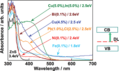 | ||
| Fig. 32 Diffuse reflection spectra of metal ion-doped ZnS photocatalysts. | ||
9.3 Solid solution photocatalysts330–332,343–348
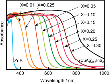
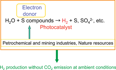
CdS and ZnS possess the same crystal structure indicating that they can form solid solutions. The CdS–ZnS solid solution is active for H2 evolution.Solid solutions of AgInS2–ZnS, CuInS2–ZnS and CuInS2–AgInS2–ZnS that are designed according to the strategy as shown in Fig. 23(c) show high photocatalytic activities for H2 evolution from aqueous sulfide and sulfite solutions under visible light irradiation. A solid solution photocatalyst of AgGa0.9In0.1S2 is also active. The solid solution formation is usually confirmed by X-ray diffraction. Peaks of XRD shift with the composition of the solid solution according to the difference in ionic radii between metal cations. The diffuse reflectance spectra of AgInS2–CuInS2–ZnS solid solutions shift monotonically with the composition of the solid solution as shown in Fig. 33. DFT calculation indicates that the levels of the conduction band consisting of Zn 4s4p and In 5s5p, and of the valence band consisting of Cu 3d, Ag 4d and S 3p, shift with the varying composition. Ru/Cu0.25Ag0.25In0.5ZnS2 shows an excellent activity for H2 evolution with a solar simulator (AM-1.5). These sulfide solid solution photocatalysts can utilize visible light of wavelengths up to about 700 nm. Moreover, solid solutions of AgInS2-CuInS2 are black photocatalysts with about 1.5 eV band gap for H2 evolution. The black photocatalysts can utilize near-infrared radiation up to 820 nm. The authors have demonstrated solar hydrogen products from an aqueous Na2S + K2SO3 solution using the AgInS2–CuInS2–ZnS solid solution photocatalyst and a reactor of 1 m2. H2 evolution at a rate of about 2 L/m2 h was observed in November in Tokyo. This photocatalytic H2 evolution will be important if abundant sulfur compounds in chemical industries or nature can be used as electron donors as shown in Fig. 34. Ideally, this reaction produces H2 at ambient temperature and pressure but does not consume fossil fuels and does not emit CO2. It should be noted that the photocatalytic H2 evolution is not a solar energy conversion because the change in the Gibbs free energy is not so positive. Toji’s group have studied CdS and ZnS photocatalysts with shell structure in the presence of an electron donor aiming at solar hydrogen production.350
AgInS2–ZnS and CuInS2–ZnS solid solution materials are applied to unique luminescent materials of which emission wavelengths are tuneable with the ratio of the solid solutions.351–353
10. Conclusions
Energy and environment issues are discussed in literature.354–359 Solar water splitting including photocatalytic processes is focused on as a candidate of the science and technology for solving the issues in the future.354,358,359 The number of photocatalysts for water splitting was very limited about twenty years ago. Furthermore, the only well-known visible light driven photocatalysts were CdS and WO3 for H2 and O2 evolution, respectively, even in the presence of sacrificial reagents. Now, many photocatalyst materials have been developed as introduced in the present review paper. So, we are sure that this research area is progressing. For example, a highly efficient water splitting was achieved using a powdered photocatalyst of NiO/NaTaO3:La under UV irradiation. The finding has proven that highly efficient water splitting is actually possible using powered photocatalysts. New powdered photocatalyst systems of oxynitrides such as CrxRh2−xO3/GaN:ZnO and Z-scheme systems such as Ru/SrTiO3:Rh-BiVO4 have been developed for overall water splitting under visible light irradiation after about 35 years from the report of the Honda–Fujishima effect. Solar water splitting is confirmed using the Ru/SrTiO3:Rh–BiVO4 photocatalyst system. Moreover, in the presence of sulfur compounds as electron donors, the sulfide solid solution photocatalysts AgInS2–CuInS2–ZnS are highly active for H2 evolution under solar light irradiation. H2 is thus realistically obtained under sunlight irradiation. Thus, the library of photocatalyst materials has become plentiful. The photocatalyst library will give information on factors affecting photocatalytic abilities and the further development of new photocatalysts. The science for understanding photocatalytic processes is also developed.40,168,251,360,361The target for efficiency for water splitting into H2 and O2 is 30% in terms of a quantum yield at 600 nm in this research field. This efficiency gives about 5% of solar energy conversion. The CrxRh2−xO3/GaN:ZnO and Ru/SrTiO3:Rh-BiVO4 photocatalysts respond to about 500 nm for overall water splitting so approaching this target but the quantum yield is still low. So, surveying photocatalyst materials are still important. It will be also important to construct the operating system for photocatalytic hydrogen production. Such an achievement will contribute to global energy and environmental issues in the future resulting in bringing about an energy revolution.
Acknowledgements
This work was supported by the Core Research for Evolutional Science and Technology (CREST) program of the Japan Science and Technology (JST) Agency, and a Grant-in-Aid for Priority Area Research from the Ministry of Education, Culture, Science, and Technology. The authors thank Dr Kato, Dr Tsuji, Prof. Domen, Prof. Kakihana, Prof. Kobayashi, Prof. Kohtani, Prof. Onishi and Prof. Torimoto for their collaborations and valuable discussions.References
- A. Fujishima, T. N. Rao and D. A. Tryk, J. Photochem. Photobiol., C, 2000, 1, 1 CrossRef CAS.
- A. Fujishima, X. Zhang and D. A. Tryk, Int. J. Hydrogen Energy, 2007, 32, 2664 CrossRef CAS.
- A. Fujishima and K. Honda, Nature, 1972, 238, 37 CAS.
- M. Grätzel, Energy Resources through Photochemistry and Catalysis, Academic Press, New York, 1983 Search PubMed.
- N. Serpone and E. Pelizzetti, Photocatalysis, Wiley, New York, 1989 Search PubMed.
- H. Yoneyama, Crit. Rev. Solid State Mater. Sci., 1993, 18, 69 CrossRef CAS.
- A. Kudo, Hyomen, 1998, 36, 625 Search PubMed [in Japanese].
- K. Domen, J. N. Kondo, M. Hara and T. Takata, Bull. Chem. Soc. Jpn., 2000, 73, 1307 CrossRef CAS.
- H. Arakawa and K. Sayama, Catal. Surv. Jpn., 2000, 4, 75 CrossRef CAS.
- K. Domen, M. Hara, J. N. Kondo, T. Takata, A. Kudo, H. Kobayashi and Y. Inoue, Korean J. Chem. Eng., 2001, 18, 862 Search PubMed.
- A. Kudo, J. Ceram. Soc. Jpn., 2001, 109, 81.
- A. Kudo, Catal. Surv. Asia, 2003, 7, 31 CrossRef CAS.
- Z. Zou and H. Arakawa, J. Photochem. Photobiol., A, 2003, 158, 145 CrossRef CAS.
- H. Yamashita, M. Takeuchi and M. Anpo, Encyclopedia of Nanoscience and Nanotechnology, American Scientific Publishers, California, 2004, 10, p. 639 Search PubMed.
- M. Anpo, S. Dohshi, M. Kitano, Y. Hu, M. Takeuchi and M. Matsuoka, Annu. Rev. Mater. Res., 2005, 35, 1 CrossRef CAS.
- J. S. Lee, Catal. Surv. Asia, 2005, 9, 217 CrossRef CAS.
- A. Kudo, Int. J. Hydrogen Energy, 2006, 31, 197 CrossRef CAS.
- Y. Inoue, Chem. Ind., 2006, 108, 623 CAS.
- W. Zhang, S. B. Park and E. Kim, Photo/Electrochemistry and Photobiology in the Environment, Energy and Fuel, 2006, 295 Search PubMed.
- K. Maeda, K. Teramura, N. Saito, Y. Inoue, H. Kobayashi and K. Domen, Pure Appl. Chem., 2006, 78, 2267 CrossRef CAS.
- W. Shanguan, Sci. Technol. Adv. Mater., 2007, 8, 76 CrossRef.
- A. Kudo, Pure Appl. Chem., 2007, 79, 1917 CrossRef CAS.
- A. Kudo, Int. J. Hydrogen Energy, 2007, 32, 2673 CrossRef CAS.
- K. Maeda and K. Domen, J. Phys. Chem. C, 2007, 111, 7851 CrossRef CAS.
- K. Maeda, K. Teramura and K. Domen, Catal. Surv. Asia, 2007, 11, 145 CrossRef CAS.
- S. Ekambaram, J. Alloys Compd., 2008, 448, 238 CrossRef CAS.
- M. Laniecki, Ceram. Eng. Sci. Proc., 2008, 28, 23 Search PubMed.
- F. E. Osterloh, Chem. Mater., 2008, 20, 35 CrossRef CAS.
- J. Nozik, Annu. Rev. Phys. Chem., 1978, 29, 189 CAS.
- Y. V. Pleskov and Y. Y. Gurevich, in Semiconductor Photoelectrochemistry, ed. P. N. Bartlett, Plenum, New York, 1986 Search PubMed.
- K. Tomita, V. Petrykin, M. Kobayashi, M. Shiro, M. Yoshimura and M. Kakihana, Angew. Chem., Int. Ed., 2006, 45, 2378 CrossRef CAS.
- Y. Oosawa and M. Gätzel, J. Chem. Soc., Faraday Trans. 1, 1988, 84, 197 RSC.
- T. Kawai and T. Sakata, Nature (London, U. K.), 1979, 282, 283 Search PubMed.
- T. Kawai and T. Sakata, J. Chem. Soc., Chem. Commun., 1979, 1047 RSC.
- T. Kawai and T. Sakata, Nature (London, U. K.), 1980, 286, 474 Search PubMed.
- T. Kawai and T. Sakata, J. Chem. Soc., Chem. Commun., 1980, 694 RSC.
- T. Kawai and T. Sakata, Chem. Lett., 1981, 10, 81 CrossRef.
- T. Sakata and T. Kawai, Nouv. J. Chim., 1981, 5, 579 Search PubMed.
- S. Ikeda, T. Takata, M. Komoda, M. Hara, J. N. Kondo, K. Domen, A. Tanaka, H. Hosono and H. Kawazoe, Phys. Chem. Chem. Phys., 1999, 1, 4485 RSC.
- B. Ohtani, Chem. Lett., 2008, 37, 217 CAS.
- S. Sato and J. M. White, Chem. Phys. Lett., 1980, 72, 83 CrossRef CAS.
- J.-M. Lehn, J.-P. Sauvage and R. Ziessel, Nouv. J. Chim., 1980, 4, 623 Search PubMed.
- K. Yamaguti and S. Sato, J. Chem. Soc., Faraday Trans. 1, 1985, 81, 1237 RSC.
- G. R. Bamwenda, S. Tshbota, T. Nakamura and M. Haruta, J. Photochem. Photobiol., A, 1995, 89, 177 CrossRef CAS.
- A. Iwase, H. Kato and A. Kudo, Catal. Lett., 2006, 108, 7 CrossRef CAS.
- K. Domen, S. Naito, S. Soma, M. Onishi and K. Tamaru, J. Chem. Soc., Chem. Commun., 1980, 543 RSC.
- T. Kawai and T. Sakata, Chem. Phys. Lett., 1980, 72, 87 CrossRef CAS.
- Y. Inoue, O. Hayashi and K. Sato, J. Chem. Soc., Faraday Trans., 1990, 86, 2277 RSC.
- K. Maeda, K. Teramura, D. Lu, N. Saito, Y. Inoue and K. Domen, Angew. Chem., Int. Ed., 2006, 45, 7806 CrossRef CAS.
- K. Maeda, K. Teramura, D. Lu, N. Saito, Y. Inoue and K. Domen, J. Catal., 2006, 243, 303 CrossRef CAS.
- A. Iwase, H. Kato and A. Kudo, Chem. Lett., 2005, 34, 946 CrossRef CAS.
- M. Hara, C. C. Waraksa, J. T. Lean, B. A. Lewis and T. E. Mallouk, J. Phys. Chem. A, 2000, 104, 5275 CrossRef CAS.
- A. Ishikawa, T. Takata, J. N. Kondo, M. Hara, H. Kobayashi and K. Domen, J. Am. Chem. Soc., 2002, 124, 13547 CrossRef CAS.
- A. Kudo, K. Domen, K. Maruya and T. Onishi, Chem. Phys. Lett., 1987, 133, 517 CrossRef CAS.
- K. Sayama and H. Arakawa, J. Chem. Soc., Faraday Trans., 1997, 93, 1647 RSC.
- S. Tabata, N. Nishida, Y. Masaki and K. Tabata, Catal. Lett., 1995, 34, 245 CrossRef CAS.
- S.-C. Moon, H. Mametsuka, E. Suzuki and M. Anpo, Chem. Lett., 1998, 27, 117 CrossRef.
- H. Mizoguchi, K. Ueda, M. Orita, S. C. Moon, K. Kajihara, M. Hirano and H. Hosono, Mater. Res. Bull., 2002, 37, 2401 CrossRef CAS.
- K. Domen, S. Naito, T. Onishi, T. Tamaru and M. Soma, J. Phys. Chem., 1982, 86, 3657 CrossRef CAS.
- K. Domen, S. Naito, T. Onishi and K. Tamaru, Chem. Phys. Lett., 1982, 92, 433 CrossRef CAS.
- K. Domen, A. Kudo, T. Onishi, N. Kosugi and H. Kuroda, J. Phys. Chem., 1986, 90, 292 CrossRef CAS.
- K. Domen, A. Kudo and T. Ohnishi, J. Catal., 1986, 102, 92 CrossRef CAS.
- A. Kudo, A. Tanaka, K. Domen and T. Onishi, J. Catal., 1988, 111, 296 CAS.
- K. Yamaguti and S. Sato, Nouv. J. Chim., 1986, 10, 217 Search PubMed.
- H. Jeong, T. Kim, D. Kim and K. Kim, Int. J. Hydrogen Energy, 2006, 31, 1142 CrossRef CAS.
- Y. G. Ko and W. Y. Lee, Catal. Lett., 2002, 83, 157 CrossRef CAS.
- T. Takata, Y. Furumi, K. Shinohara, A. Tanaka, M. Hara, J. N. Kondo and K. Domen, Chem. Mater., 1997, 9, 1063 CrossRef CAS.
- S. Ikeda, M. Hara, J. N. Kondo, K. Domen, H. Takahashi, T. Okubo and M. Kakihana, Chem. Mater., 1998, 10, 72 CrossRef CAS.
- J. Kim, D. W. Hwang, H. G. Kim, S. W. Bae, J. S. Lee, W. Li and S. H. Oh, Top. Catal., 2005, 35, 295 CrossRef CAS.
- H. G. Kim, D. W. Hwang, J. Kim, Y. G. Kim and J. S. Lee, Chem. Commun., 1999, 1077 RSC.
- A. Kim, D. W. Hwang, S. W. Bae, Y. G. Kim and J. S. Lee, Korean J. Chem. Eng., 2001, 18, 941 Search PubMed.
- J. Kim, D. W. Hwang, H. G. Kim, S. W. Bae, S. M. Ji and J. S. Lee, Chem. Commun., 2002, 2488 RSC.
- D. W. Hwang, J. S. Lee, W. Li and S. H. Oh, J. Phys. Chem. B, 2003, 107, 4963 CrossRef CAS.
- H. G. Kim, D. W. Hwang, S. W. Bae, J. H. Jung and J. S. Lee, Catal. Lett., 2003, 91, 193 CrossRef CAS.
- H. G. Kim, S. M. Ji, J. S. Jang, S. W. Bae and J. S. Lee, Korean J. Chem. Eng., 2004, 21, 970 Search PubMed.
- R. Abe, M. Higashi, K. Sayama, Y. Abe and H. Sugihara, J. Phys. Chem. B, 2006, 110, 2219 CrossRef CAS.
- H. Song, P. Cai, Y. Huabing and C. Yan, Catal. Lett., 2007, 113, 54 CrossRef CAS.
- S. M. Ji, H. Jun, J. S. Jang, H. C. Son, P. H. Borse and J. S. Lee, J. Photochem. Photobiol., A, 2007, 189, 141 CrossRef CAS.
- V. R. Reddy, D. W. Hwang and J. S. Lee, Catal. Lett., 2003, 90, 39 CrossRef CAS.
- H. Takahashi, M. Kakihana, Y. Yamashita, K. Yoshida, S. Ikeda, M. Hara and K. Domen, J. Alloys Compd., 1999, 285, 77 CrossRef CAS.
- Y. Inoue, T. Kubokawa and K. Sato, J. Chem. Soc., Chem. Commun., 1990, 1298 RSC.
- Y. Inoue, T. Kubokawa and K. Sato, J. Phys. Chem., 1991, 95, 4059 CrossRef CAS.
- Y. Inoue, S. Ogura, M. Kohno and K. Sato, Appl. Surf. Sci., 1997, 121/122, 521 CrossRef.
- S. Ogura, K. Sato and Y. Inoue, Phys. Chem. Chem. Phys., 2000, 2, 2449 RSC.
- Y. Inoue, T. Niiyama, Y. Asai and K. Sato, J. Chem. Soc., Chem. Commun., 1992, 579 RSC.
- Y. Inoue, Y. Asai and K. Sato, J. Chem. Soc., Faraday Trans., 1994, 90, 797 RSC.
- Y. Inoue, M. Kohno, S. Ogura and K. Sato, Chem. Phys. Lett., 1997, 267, 72 CrossRef CAS.
- Y. Inoue, M. Kohno, S. Ogura and K. Sato, J. Chem. Soc., Faraday Trans., 1997, 93, 2433 RSC.
- Y. Inoue, M. Kohno, T. Kaneko, S. Ogura and K. Sato, J. Chem. Soc., Faraday Trans., 1998, 94, 89 RSC.
- T. Sato, M. Kakihana, M. Arima, K. Yoshida, Y. Yamashita, M. Yashima and M. Yoshimura, Appl. Phys. Lett., 1996, 69, 2053 CrossRef.
- R. Abe, M. Higashi, Z. G. Zou, K. Sayama and Y. Abe, Chem. Lett., 2004, 33, 954 CrossRef CAS.
- M. Higashi, R. Abe, K. Sayama, H. Sugihara and Y. Abe, Chem. Lett., 2005, 34, 1122 CrossRef CAS.
- K. Sayama and H. Arakawa, J. Phys. Chem., 1993, 97, 531 CrossRef CAS.
- K. Sayama and H. Arakawa, J. Photochem. Photobiol., A, 1994, 77, 243 CrossRef CAS.
- K. Sayama and H. Arakawa, J. Photochem. Photobiol., A, 1996, 94, 67 CrossRef CAS.
- V. R. Reddy, D. W. Hwang and J. S. Lee, Korean J. Chem. Eng., 2003, 20, 1026 Search PubMed.
- J. J. Zou, C. J. Liu and Y. P. Zhang, Langmuir, 2006, 22, 2334 CrossRef CAS.
- K. Domen, A. Kudo, A. Shinozaki, A. Tanaka, K. Maruya and T. Onishi, J. Chem. Soc., Chem. Commun., 1986, 356 RSC.
- K. Domen, A. Kudo, M. Shibata, A. Tanaka, K. Maruya and T. Onishi, J. Chem. Soc., Chem. Commun., 1986, 1706 RSC.
- A. Kudo, A. Tanaka, K. Domen, K. Maruya, K. Aika and T. Onishi, J. Catal., 1988, 111, 67 CrossRef CAS.
- A. Kudo, K. Sayama, A. Tanaka, K. Asakura, K. Domen, K. Maruya and T. Onishi, J. Catal., 1989, 120, 337 CrossRef CAS.
- K. Domen, A. Kudo, A. Tanaka and T. Onishi, Catal. Today, 1990, 8, 77 CrossRef CAS.
- K. Sayama, A. Tanaka, K. Domen, K. Maruya and T. Onishi, J. Phys. Chem., 1991, 95, 1345 CrossRef CAS.
- K. Sayama, A. Tanaka, K. Domen, K. Maruya and T. Onishi, Catal. Lett., 1990, 4, 217 CrossRef CAS.
- K. Sayama, H. Arakawa and K. Domen, Catal. Today, 1996, 28, 175 CrossRef CAS.
- S. Ikeda, A. Tanaka, K. Shinohara, M. Hara, J. N. Kondo, K. Maruya and K. Domen, Microporous Mesoporous Mater., 1997, 9, 253 CAS.
- K. H. Chung and D. C. Park, J. Photochem. Photobiol., A, 1998, 129, 53 CAS.
- K. Sayama, K. Yase, H. Arakawa, K. Asakura, A. Tanaka, K. Domen and T. Onishi, J. Photochem. Photobiol., A, 1998, 114, 125 CrossRef CAS.
- A. Kudo, H. Kato and S. Nakagawa, J. Phys. Chem. B, 2000, 104, 571 CrossRef CAS.
- H. Kato and A. Kudo, J. Photochem. Photobiol., A, 2001, 145, 129 CrossRef CAS.
- M. Yoshino, M. Kakihana, W. S. Cho, H. Kato and A. Kudo, Chem. Mater., 2002, 14, 3369 CrossRef CAS.
- Y. Miseki, H. Kato and A. Kudo, Chem. Lett., 2006, 35, 1052 CrossRef CAS.
- Y. Ebina, N. Sakai and T. Sasaki, J. Phys. Chem. B, 2005, 109, 17212 CrossRef CAS.
- A. Kudo, S. Nakagawa and H. Kato, Chem. Lett., 1999, 28, 1197 CrossRef.
- Y. Miseki, H. Kato and A. Kudo, Chem. Lett., 2005, 34, 54 CrossRef CAS.
- R. Abe, M. Higashi, Z. G. Zou, K. Sayama and H. Arakawa, J. Phys. Chem. B, 2004, 108, 811 CrossRef CAS.
- H. Kato and A. Kudo, Chem. Phys. Lett., 1998, 295, 487 CrossRef CAS.
- Y. Takahara, J. N. Kondo, T. Takata, D. Lu and K. Domen, Chem. Mater., 2001, 13, 1194 CrossRef CAS.
- A. Kudo, H. Okutomi and H. Kato, Chem. Lett., 2000, 29, 1212 CrossRef.
- A. Kudo and H. Kato, Chem. Lett., 1997, 26, 867 CrossRef.
- T. Kurihara, H. Okutomi, Y. Miseki, H. Kato and A. Kudo, Chem. Lett., 2006, 35, 274 CrossRef CAS.
- H. Kato and A. Kudo, J. Phys. Chem. B, 2001, 105, 4285 CrossRef CAS.
- H. Kato and A. Kudo, Catal. Lett., 1999, 58, 153 CrossRef CAS.
- H. Kato and A. Kudo, Catal. Today, 2003, 78, 561 CrossRef CAS.
- H. Kato, H. Kobayashi and A. Kudo, J. Phys. Chem. B, 2002, 106, 12441 CrossRef CAS.
- C. Mitsui, H. Nishiguchi, K. Fukamachi, T. Ishihara and Y. Takita, Chem. Lett., 1999, 28, 1327 CrossRef.
- T. Ishihara, H. Nishiguchi, K. Fukamachi and Y. Takita, J. Phys. Chem. B, 1999, 103, 1 CrossRef CAS.
- A. Kudo and H. Kato, Chem. Phys. Lett., 2000, 331, 373 CrossRef CAS.
- H. Kato, K. Asakura and A. Kudo, J. Am. Chem. Soc., 2003, 125, 3082 CrossRef CAS.
- A. Iwase, H. Kato, H. Okutomi and A. Kudo, Chem. Lett., 2004, 33, 1260 CrossRef CAS.
- S. Ikeda, M. Fubuki, Y. K. Takahara and M. Matsumura, Appl. Catal., A, 2006, 300, 186 CrossRef CAS.
- T. Ishihara, N. S. Baik, N. Ono, H. Nishiguchi and Y. Takita, J. Photochem. Photobiol., A, 2004, 167, 149 CrossRef CAS.
- H. Kato and A. Kudo, Chem. Lett., 1999, 28, 1207 CrossRef.
- K. Yoshioka, V. Petrykin, M. Kakihana, H. Kato and A. Kudo, J. Catal., 2005, 232, 102 CrossRef CAS.
- K. Shimizu, Y. Tsuji, T. Hatamachi, K. Toda, T. Kodama, M. Sato and Y. Kitayama, Phys. Chem. Chem. Phys., 2004, 6, 1064 RSC.
- M. Machida, J. Yabunaka and T. Kijima, Chem. Commun., 1999, 1939 RSC.
- M. Machida, J. Yabunaka and T. Kijima, Chem. Mater., 2000, 12, 812 CrossRef CAS.
- M. Machida, J. Yabunaka, T. Kijima, S. Matsushita and M. Arai, Int. J. Inorg. Chem., 2001, 3, 545 Search PubMed.
- M. Machida, K. Miyazaki, S. Matsushita and M. Arai, J. Mater. Chem., 2003, 13, 1433 RSC.
- K. Shimizu, S. Itoh, T. Hatamachi, T. Kodama, M. Sato and K. Toda, Chem. Mater., 2005, 17, 5161 CrossRef CAS.
- W. Yao and J. Ye, Chem. Phys. Lett., 2007, 435, 96 CrossRef CAS.
- T. Mitsuyama, A. Tsutsui, T. Hara, K. Ikeue and M. Machida, Bull. Chem. Soc. Jpn., 2008, 81, 401 CrossRef CAS.
- H. Otsuka, K. Kim, A. Kouzu, I. Takimoto, H. Fujimori, Y. Sakata, H. Imamura, T. Matsumoto and K. Toda, Chem. Lett., 2005, 34, 822 CrossRef CAS.
- Y. Li, G. Chen, C. Zhou and Z. Li, Catal. Lett., 2008, 123, 80 CrossRef CAS.
- J. N. Kondo, M. Uchida, K. Nakajima, L. Daling, M. Hara and K. Domen, Chem. Mater., 2004, 16, 4304 CrossRef CAS.
- M. Machida, S. Murakami and T. Kijima, J. Phys. Chem. B, 2001, 105, 3289 CrossRef CAS.
- N. Saito, H. Kadowaki, H. Kobayashi, K. Ikarashi, H. Nishiyama and Y. Inoue, Chem. Lett., 2004, 33, 2004.
- H. Kadowaki, N. Saito, H. Nishiyama, H. Kobayashi, Y. Shimodaira and Y. Inoue, J. Phys. Chem. C, 2007, 111, 439 CrossRef CAS.
- S. Ikeda, T. Itani, K. Nango and M. Matsumura, Catal. Lett., 2004, 98, 229 CrossRef CAS.
- H. Kadowaki, N. Saito, H. Nishiyama and Y. Inoue, Chem. Lett., 2007, 36, 440 CrossRef CAS.
- Y. Yuan, J. Zheng, X. Zhang, Z. Li, T. Yu, J. Ye and Z. Zou, Solid State Ionics, 2008, 178, 1711 CrossRef CAS.
- M. Kakihana and K. Domen, MRS Bull., 2000, 25, 27 CAS.
- J. G. Mavroides, J. A. Kafalas and D. F. Kolesar, Appl. Phys. Lett., 1976, 28, 241 CrossRef CAS.
- A. B. Ellis, S. W. Kaiser and M. S. Wrighton, J. Phys. Chem., 1976, 80, 1325 CrossRef CAS.
- A. Kudo, K. Domen, K. Maruya and T. Onishi, Chem. Lett., 1987, 16, 1019 CrossRef.
- A. Kudo, K. Domen, K. Maruya and T. Onishi, J. Catal., 1992, 135, 300 CrossRef CAS.
- H. Kato and A. Kudo, Phys. Chem. Chem. Phys., 2002, 4, 2833 RSC.
- H. Hagiwara, N. Ono, T. Inoue, H. Matsumoto and T. Ishihara, Angew. Chem., Int. Ed., 2006, 45, 1420 CrossRef CAS.
- H. Yoshida, S. Kato, K. Hirao, J. Nishimoto and T. Hattori, Chem. Lett., 2007, 36, 430 CrossRef CAS.
- J. F. Luan, S. R. Zheng, X. P. Hao, G. Y. Luan, X. Wu and Z. Zou, J. Braz. Chem. Soc., 2006, 17, 1368 CAS.
- J. F. Luan, X. P. Hao, S. R. Zheng, G. Y. Luan and X. S. Wu, J. Mater. Sci., 2006, 41, 8001 CrossRef CAS.
- N. Ishizawa, F. Marumo, T. Kawamura and M. Kimura, Acta Crystallogr., Sect. B: Struct. Crystallogr. Cryst. Chem., 1975, 31, 1912 CrossRef.
- N. Ishizawa, F. Marumo, T. Kawamura and M. Kimura, Acta Crystallogr., Sect. B: Struct. Crystallogr. Cryst. Chem., 1976, 32, 2564 CrossRef.
- D. E. Scaife, Sol. Energy, 1980, 25, 41 CrossRef CAS.
- M. P. Dare-Edwards, J. P. Goodenough, A. Hamnett and N. D. Nicholson, J. Chem. Soc., Faraday Trans. 2, 1981, 77, 643 RSC.
- M. Wiegel, M. H. J. Emond, E. R. Stobbe and G. J. Blasse, J. Phys. Chem. Solids, 1994, 55, 773 CrossRef.
- Z. Zou, J. Ye and H. Arakawa, Chem. Phys. Lett., 2000, 332, 271 CrossRef CAS.
- A. Yamakata, T. Ishibashi, H. Kato, A. Kudo and H. Onishi, J. Phys. Chem. B, 2003, 51, 14383 CrossRef.
- J. Sato, H. Kobayashi, N. Saito, H. Nishiyama and Y. Inoue, J. Photochem. Photobiol., A, 2003, 158, 139 CrossRef CAS.
- J. Sato, H. Kobayashi and Y. Inoue, J. Phys. Chem. B, 2003, 107, 7970 CrossRef CAS.
- J. Sato, N. Saito, H. Nishiyama and Y. Inoue, J. Phys. Chem. B, 2001, 105, 6061 CrossRef CAS.
- J. Sato, N. Saito, H. Nishiyama and Y. Inoue, J. Phys. Chem. B, 2003, 107, 7965 CrossRef CAS.
- J. Sato, N. Saito, H. Nishiyama and Y. Inoue, Chem. Lett., 2001, 30, 868 CrossRef.
- N. Arai, N. Saito, H. Nishiyama, Y. Shimodaira, H. Kobayashi, Y. Inoue and K. Sato, J. Phys. Chem. C, 2008, 112, 5000 CrossRef CAS.
- J. Sato, N. Saito, H. Nishiyama and Y. Inoue, J. Photochem. Photobiol., A, 2002, 148, 85 CrossRef CAS.
- K. Ikarashi, J. Sato, H. Kobayashi, N. Saito, H. Nishiyama and Y. Inoue, J. Phys. Chem. B, 2002, 106, 9048 CrossRef CAS.
- J. Sato, H. Kobayashi, K. Ikarashi, N. Saito, H. Nishiyama and Y. Inoue, J. Phys. Chem. B, 2004, 108, 4369 CrossRef CAS.
- K. Ikarashi, J. Sato, H. Kobayashi, N. Saito, H. Nishiyama, Y. Simodaira and Y. Inoue, J. Phys. Chem. B, 2005, 109, 22995 CrossRef.
- T. Yanagida, Y. Sakata and H. Imamura, Chem. Lett., 2004, 33, 726 CrossRef CAS.
- Y. Sakata, Y. Matsuda, T. Yanagida, K. Hirata, H. Imamura and K. Teramura, Catal. Lett., 2008, 125, 22 CrossRef CAS.
- J. Tang, Z. Zou, J. Yin and J. Ye, Chem. Phys. Lett., 2003, 382, 175 CrossRef CAS.
- J. Tang, Z. Zou and J. Ye, Chem. Mater., 2004, 16, 1644 CrossRef CAS.
- J. Tang, Z. Zou, M. Katagiri, T. Kako and J. Ye, Catal. Today, 2004, 93, 885 CrossRef.
- J. Tang, Z. Zou and J. Ye, Res. Chem. Intermed., 2005, 31, 513 CrossRef CAS.
- M. Shibata, A. Kudo, A. Tanaka, K. Domen, K. Maruya and T. Onishi, Chem. Lett., 1987, 16, 1017 CrossRef.
- A. Kudo and T. Kondo, J. Mater. Chem., 1997, 7, 777 RSC.
- T. Sekine, J. Yoshimura, A. Tanaka, K. Domen, K. Maruya and T. Onishi, Bull. Chem. Soc. Jpn., 1990, 63, 2107 CAS.
- M. Machida, X. W. Ma, H. Taniguchi, J. Yabunaka and T. Kijima, J. Mol. Catal. A: Chem., 2000, 155, 131 CrossRef CAS.
- A. Kudo and H. Kato, Chem. Lett., 1997, 26, 421 CrossRef.
- K. Domen, Y. Ebina, T. Sekine, A. Tanaka, J. Kondo and C. Hirose, Catal. Today, 1993, 16, 479 CrossRef CAS.
- Y. Ebina, A. Tanaka, J. N. Kondo and K. Domen, Chem. Mater., 1996, 8, 2534 CrossRef CAS.
- Y. Ebina, T. Sasaki, M. Harada and M. Watanabe, Chem. Mater., 2002, 14, 4390 CrossRef CAS.
- A. Kudo and S. Hijii, Chem. Lett., 1999, 28, 1103 CrossRef.
- A. Kudo, A. Steinberg, A. J. Bard, A. Campion, M. A. Fox, T. E. Mallouk, S. E. Webber and J. M. White, Catal. Lett., 1990, 5, 61 CrossRef CAS.
- H. Kato, N. Matsudo and A. Kudo, Chem. Lett., 2004, 33, 1216 CrossRef CAS.
- A. Kudo and I. Mikami, J. Chem. Soc., Faraday Trans., 1998, 94, 2929 RSC.
- M. P. Kapoor, S. Inagaki and H. Yoshida, J. Phys. Chem. B, 2005, 109, 9231 CrossRef CAS.
- T. Sasaki, J. Ceram. Soc. Jpn., 2007, 115, 9 CrossRef CAS.
- O. C. Compton, E. C. Carroll, J. Y. Kim, D. S. Larsen and F. E. Osterloh, J. Phys. Chem. C, 2007, 111, 14589 CrossRef CAS.
- O. C. Compton, C. H. Mullet, S. Chiang and F. E. Osterloh, J. Phys. Chem. C, 2008, 112, 6202 CrossRef CAS.
- T. Yamase, Chem. Rev., 1998, 98, 307 CrossRef CAS.
- A. A. Krasnovsky and G. P. Brin, Dokl. Akad. Nauk SSSR, 1962, 147, 656.
- J. R. Darwent and A. Mills, J. Chem. Soc., Faraday Trans. 2, 1982, 78, 359 RSC.
- W. Erbs, J. Desilvestro, E. Borgarello and M. Grätzel, J. Phys. Chem., 1984, 88, 4001 CrossRef CAS.
- Y. Shimodaira, H. Kato, H. Kobayashi and A. Kudo, J. Phys. Chem. B, 2006, 110, 17790 CrossRef CAS.
- D. Wang, J. Tang, Z. Zou and J. Ye, Chem. Mater., 2005, 17, 5177 CrossRef CAS.
- W. Yao and J. Ye, Chem. Phys. Lett., 2008, 450, 370 CrossRef CAS.
- A. Kudo and I. Mikami, Chem. Lett., 1998, 10, 1027 CrossRef.
- H. Kato and A. Kudo, J. Phys. Chem. B, 2002, 106, 5029 CrossRef CAS.
- R. Niishiro, H. Kato and A. Kudo, Phys. Chem. Chem. Phys., 2005, 7, 2241 RSC.
- T. Ishii, H. Kato and A. Kudo, J. Photochem. Photobiol., A, 2004, 163, 181 CrossRef CAS.
- R. Konta, T. Ishii, H. Kato and A. Kudo, J. Phys. Chem. B, 2004, 108, 8992 CrossRef CAS.
- S. Nishimoto, M. Matsuda and M. Miyake, Chem. Lett., 2006, 35, 308 CrossRef CAS.
- D. W. Hwang, H. G. Kim, J. S. Jang, S. W. Bae, S. M. Ji and J. S. Lee, Catal. Today, 2004, 93, 845 CrossRef.
- D. W. Hwang, H. G. Kim, J. S. Lee, J. Kim, W. Le and S. H. Oh, J. Phys. Chem. B, 2005, 109, 2093 CrossRef CAS.
- R. Niishiro, R. Konta, H. Kato, W. J. Chun, K. Asakura and A. Kudo, J. Phys. Chem. C, 2007, 111, 17420 CrossRef CAS.
- Y. Shimodaira, H. Kato, H. Kobayashi and A. Kudo, Bull. Chem. Soc. Jpn., 2007, 80, 885 CrossRef CAS.
- J. Yoshimura, Y. Ebina, J. Kondo, K. Domen and A. Tanaka, J. Phys. Chem., 1993, 97, 1970 CrossRef CAS.
- H. G. Kim, D. W. Hwang and J. S. Lee, J. Am. Chem. Soc., 2004, 126, 8912 CrossRef CAS.
- H. G. Kim, O. S. Becker, J. S. Jang, S. M. Ji, P. H. Borse and J. S. Lee, J. Solid State Chem., 2006, 179, 1214 CrossRef CAS.
- A. Kudo, K. Ueda and H. Kato, Catal. Lett., 1998, 53, 229 CrossRef CAS.
- A. Kudo, K. Omori and H. Kato, J. Am. Chem. Soc., 1999, 121, 11459 CrossRef CAS.
- S. Tokunaga, H. Kato and A. Kudo, Chem. Mater., 2001, 13, 4624 CrossRef CAS.
- J. Q. Yu and A. Kudo, Adv. Funct. Mater., 2006, 16, 2163 CrossRef CAS.
- H. Liu, R. Nakamura and Y. Nakato, ChemPhysChem, 2005, 6, 2499 CrossRef CAS.
- H. Liu, R. Nakamura and Y. Nakato, Electrochem. Solid-State Lett., 2006, 9, G187 CrossRef CAS.
- Y. Hosogi, K. Tanabe, H. Kato, H. Kobayashi and A. Kudo, Chem. Lett., 2004, 33, 28 CrossRef CAS.
- Y. Hosogi, H. Kato and A. Kudo, Chem. Lett., 2006, 35, 578 CrossRef CAS.
- Y. Hosogi, Y. Shimodaira, H. Kato, H. Kobayashi and A. Kudo, Chem. Mater., 2008, 20, 1299 CrossRef CAS.
- R. Konta, H. Kato, H. Kobayashi and A. Kudo, Phys. Chem. Chem. Phys., 2003, 5, 3061 RSC.
- Y. Hosogi, H. Kato and A. Kudo, J. Mater. Chem., 2008, 18, 647 RSC.
- R. Abe, H. Takami, N. Murakami and B. Ohtani, J. Am. Chem. Soc., 2008, 130, 7780 CrossRef CAS.
- J. Yu, J. Xiong, B. Cheng, Y. Yu and J. Wang, J. Solid State Chem., 2005, 178, 1968 CrossRef CAS.
- J. Tang, Z. Zou and J. Ye, Catal. Lett., 2004, 92, 53 CrossRef CAS.
- F. Amano, K. Nogami, R. Abe and B. Otani, Chem. Lett., 2007, 36, 1314 CrossRef CAS.
- F. Amano, K. Nogami, R. Abe and B. Otani, J. Phys. Chem. C, 2008, 112, 9320 CrossRef CAS.
- H. Fu, C. Pan, W. Yao and Y. Zhu, J. Phys. Chem. B, 2005, 109, 22432 CrossRef CAS.
- C. Zhang and Y. Zhu, Chem. Mater., 2005, 17, 3537 CrossRef CAS.
- S. Zhang, C. Zhang, Y. Man and Y. Zhu, J. Solid State Chem., 2006, 179, 62 CrossRef CAS.
- S. Zhu, T. Xu, H. Fu, J. Zhao and Y. Zhu, Environ. Sci. Technol., 2007, 41, 6234 CrossRef CAS.
- J. Wu, F. Duan, Y. Zheng and Y. Xie, J. Phys. Chem. C, 2007, 111, 12866 CrossRef CAS.
- J. Li, X. Zhang, Z. Ai, F. Jia, L. Zhang and J. Lin, J. Phys. Chem. C, 2007, 111, 6832 CrossRef CAS.
- S. Zhang, J. Shen, H. Fu, W. Dong, Z. Zheng and L. Shi, J. Solid State Chem., 2007, 180, 1165 CrossRef.
- H. Xie, D. Shen, X. Wang and G. Shen, Mater. Chem. Phys., 2007, 103, 334 CrossRef CAS.
- H. Fu, C. Pan, L. Zhang and Y. Zhu, Mater. Res. Bull., 2007, 42, 696 CrossRef CAS.
- L. Wu, J. Bi, Z. Li, X. Wang and X. Fu, Catal. Today, 2008, 131, 15 CrossRef CAS.
- H. Fu, S. Zhang, T. Xu, Y. Zhu and J. Chen, Environ. Sci. Technol., 2008, 42, 2085 CrossRef CAS.
- L. Zhou, W. Wang and L. Zhang, J. Mol. Catal. A: Chem., 2007, 268, 195 CrossRef CAS.
- C. A. Martinez-de la, S. O. Alfaro, E. L. Cuellar and U. O. Mendez, Catal. Today, 2007, 129, 194 CrossRef.
- R. Asahi, T. Morikawa, T. Ohwaki, K. Aoki and Y. Taga, Science, 2001, 293, 269 CrossRef CAS.
- T. Ikeda, T. Nomoto, K. Eda, Y. Mizutani, H. Kato, A. Kudo and H. Onishi, J. Phys. Chem. C, 2008, 112, 1167 CrossRef CAS.
- S. Kohtani, A. Koshiko, A. Kudo, K. Tokumura, Y. Ishigaki, A. Toriba, K. Hayakawa and R. Nakagaki, Appl. Catal., B, 2003, 46, 573 CrossRef CAS.
- X. Zhang, Z. Ai, F. Jia, L. Zhang, X. Fan and Z. Zou, Mater. Chem. Phys., 2007, 103, 162 CrossRef CAS.
- H. Xu, H. Li, C. Wu, J. Chu, Y. Yan, H. Shu and Z. Gu, J. Hazard. Mater., 2008, 153, 877 CrossRef CAS.
- L. Zhou, W. Wang, S. Liu, L. Zhang, H. Xu and W. Zhu, J. Mol. Catal. A: Chem., 2006, 252, 120 CrossRef CAS.
- L. Ge, Mater. Chem. Phys., 2008, 107, 465 CrossRef CAS.
- L. Ge, Mater. Lett., 2008, 62, 926 CrossRef CAS.
- L. Ge, J. Inorg. Mater., 2008, 23, 449 Search PubMed.
- L. Zhou, W. Wang, L. Zhang, H. Xu and W. Zhu, J. Phys. Chem. C, 2007, 111, 13659 CrossRef CAS.
- Y. Zheng, J. Wu, F. Duan and Y. Xie, Chem. Lett., 2007, 36, 520 CrossRef CAS.
- S. Kohtani, S. Makino, A. Kudo, K. Tokumura, Y. Ishigaki, T. Matsunaga, O. Nikaido, K. Hayakawa and R. Nakagaki, Chem. Lett., 2002, 7, 660 CrossRef.
- S. Kohtani, J. Hiro, N. Yamamoto, A. Kudo, K. Tokumura and R. Nakagaki, Catal. Commun., 2005, 6, 185 CrossRef CAS.
- S. Kohtani, M. Tomohiro, K. Tokumura and R. Nakagaki, Appl. Catal., B, 2005, 58, 265 CrossRef CAS.
- S. Kohtani, Y. Inaoka, K. Hayakawa and R. Nakagaki, J. Adv. Oxid. Technol., 2007, 10, 381 Search PubMed.
- S. Kohtani, K. Yoshida, T. Maekawa, A. Iwase, A. Kudo, H. Miyabe and R. Nakagaki, Phys. Chem. Chem. Phys., 2008, 10, 2986 RSC.
- S. Kohtani, N. Yamamoto, K. Kitajima, A. Kudo, H. Kato, K. Tokumura, K. Hayakawa and R. Nakagaki, Photo/Electrochem. Photobiol. Environ. Energy Fuel, 2004, 173 Search PubMed.
- H. Irie, Y. Maruyama and K. Hashimoto, J. Phys. Chem. C, 2007, 111, 1847 CrossRef CAS.
- G. Li, T. Kako, D. Wang, Z. Zou and J. Ye, J. Solid State Chem., 2007, 180, 2845 CrossRef CAS.
- D. Wang, T. Kako and J. Ye, J. Am. Chem. Soc., 2008, 130, 2724 CrossRef CAS.
- T. Kajiwara, K. Hasimoto, T. Kawai and T. Sakata, J. Phys. Chem., 1982, 86, 4516 CrossRef CAS.
- K. Hashimoto, T. Kawai and T. Sakata, Nouv. J. Chim., 1983, 7, 249 Search PubMed.
- T. Shimidzu, T. Iyoda and Y. Koide, J. Am. Chem. Soc., 1985, 107, 35 CrossRef CAS.
- Y. I. Kim, S. J. Atherton, E. S. Brigham and T. E. Mallouk, J. Phys. Chem., 1993, 97, 11802 CrossRef CAS.
- E. A. Malinka, G. L. Kamalov, S. V. Vodzinskii, V. I. Melnik and Z. I. Zhilina, J. Photochem. Photobiol., A, 1995, 90, 153 CrossRef CAS.
- R. Abe, K. Sayama and H. Arakawa, Chem. Phys. Lett., 2003, 379, 230 CrossRef CAS.
- R. Abe, K. Sayama and H. Arakawa, J. Photochem. Photobiol., A, 2004, 166, 115 CrossRef CAS.
- J. Yoshimura, A. Kudo, A. Tanaka, K. Domen, K. Maruya and T. Onishi, Chem. Phys. Lett., 1988, 147, 401 CrossRef CAS.
- J. Yoshimura, A. Tanaka, J. N. Kondo and K. Domen, Bull. Chem. Soc. Jpn., 1995, 68, 2439 CAS.
- S. Tawkaew, Y. Fujishiro, S. Yin and T. Sato, Colloids Surf., A, 2001, 179, 139 CrossRef CAS.
- Z. Tong, S. Takagi, H. Tachibana, K. Takagi and H. Inoue, J. Phys. Chem. B, 2005, 109, 21612 CrossRef CAS.
- A. Kasahara, K. Nukumizu, G. Hitoki, T. Takata, J. N. Kondo, M. Hara, H. Kobayashi and K. Domen, J. Phys. Chem. A, 2002, 106, 6750 CrossRef CAS.
- G. Hitoki, T. Takata, J. N. Kondo, M. Hara, H. Kobayashi and K. Domen, Chem. Commun., 2002, 1698 RSC.
- M. Hara, J. Nunoshige, T. Takata, J. N. Kondo and K. Domen, Chem. Commun., 2003, 3000 RSC.
- M. Hara, G. Hitoki, T. Takata, J. N. Kondo, H. Kobayashi and K. Domen, Catal. Today, 2003, 78, 555 CrossRef CAS.
- M. Hara, T. Takata, J. N. Kondo and K. Domen, Catal. Today, 2004, 90, 313 CrossRef CAS.
- T. Takata, G. Hitoki, J. N. Kondo, M. Hara, H. Kobayashi and K. Domen, Res. Chem. Intermed., 2007, 33, 13 CrossRef CAS.
- G. Hitoki, A. Ishikawa, J. N. Kondo, M. Hara and K. Domen, Chem. Lett., 2002, 31, 736 CrossRef.
- Y. Lee, K. Nukumizu, T. Watanabe, T. Takata, M. Hara, M. Yoshimura and K. Domen, Chem. Lett., 2006, 35, 352 CrossRef CAS.
- G. Hitoki, T. Takata, J. N. Kondo, M. Hara, H. Kobayashi and K. Domen, Electrochemistry (Tokyo, Jpn.), 2002, 70, 463 CAS.
- D. Yamasita, T. Takata, M. Hara, J. N. Kondo and K. Domen, Solid State Ionics, 2004, 172, 591 CrossRef CAS.
- M. Liu, W. You, Z. Lei, G. Zhou, J. Yang, G. Wu, G. Ma, G. Luan, T. Takata, M. Hara, K. Domen and C. Lee, Chem. Commun., 2004, 2192 RSC.
- K. Nukumizu, J. Nunoshige, T. Takata, J. N. Kondo, M. Hara, H. Kobayashi and K. Domen, Chem. Lett., 2003, 32, 196 CrossRef CAS.
- K. Maeda, Y. Shimodaira, B. Lee, K. Teramura, D. Lu, H. Kobayashi and K. Domen, J. Phys. Chem. C, 2007, 111, 18264 CrossRef CAS.
- A. Ishikawa, Y. Yamada, T. Takata, J. N. Kondo, M. Hara. H. Kobayashi and K. Domen, Chem. Mater., 2003, 15, 4442 CrossRef CAS.
- A. Ishikawa, T. Takata, T. Matsumura, J. N. Kondo, M. Hara. H. Kobayashi and K. Domen, J. Phys. Chem. B, 2004, 108, 2637 CrossRef CAS.
- K. Ogisu, A. Ishikawa, K. Teramura, K. Toda, M. Hara and K. Domen, Chem. Lett., 2007, 36, 854 CrossRef CAS.
- A. Ishikawa, T. Takata, J. N. Kondo, M. Hara and K. Domen, J. Phys. Chem. B, 2004, 108, 11049 CrossRef CAS.
- R. Abe, T. Takata, H. Sugihara and K. Domen, Chem. Lett., 2005, 34, 1162 CrossRef CAS.
- R. Nakamura, T. Tanaka and Y. Nakato, J. Phys. Chem. B, 2005, 109, 8920 CrossRef CAS.
- J. Sato, N. Saito, Y. Yamada, K. Maeda, T. Takata, J. N. Kondo, M. Hara, H. Kobayashi, K. Domen and Y. Inoue, J. Am. Chem. Soc., 2005, 127, 4150 CrossRef CAS.
- Y. Lee, T. Watanabe, T. Takata, M. Hara, M. Yoshimura and K. Domen, J. Phys. Chem. B, 2006, 110, 17563 CrossRef CAS.
- K. Maeda, N. Saito, D. Lu, Y. Inoue and K. Domen, J. Phys. Chem. C, 2007, 111, 4749 CrossRef CAS.
- K. Maeda, N. Saito, Y. Inoue and K. Domen, Chem. Mater., 2007, 19, 4092 CrossRef CAS.
- K. Maeda, K. Teramura, N. Saito, Y. Inoue and K. Domen, Bull. Chem. Soc. Jpn., 2007, 80, 1004 CrossRef CAS.
- N. Arai, N. Saito, H. Nishiyama, Y. Inoue, K. Domen and K. Sato, Chem. Lett., 2006, 35, 796 CrossRef CAS.
- N. Arai, N. Saito, H. Nishiyama, K. Domen, H. Kobayashi, K. Sato and Y. Inoue, Catal. Today, 2007, 129, 407 CrossRef CAS.
- K. Maeda, T. Takata, M. Hara, N. Saito, Y. Inoue, H. Kobayashi and K. Domen, J. Am. Chem. Soc., 2005, 127, 8286 CrossRef CAS.
- K. Maeda, K. Teramura, T. Takata, M. Hara, N. Saito, Y. Inoue, H. Kobayashi and K. Domen, J. Phys. Chem. B, 2005, 109, 20504 CrossRef CAS.
- K. Maeda, K. Teramura, D. Lu, T. Takata, N. Saito, Y. Inoue and K. Domen, Nature, 2006, 440, 295 CrossRef CAS.
- X. Sun, K. Maeda, F. M. Le, K. Teramura and K. Domen, Appl. Catal., A, 2007, 327, 114 CrossRef CAS.
- K. Maeda, K. Teramura and K. Domen, J. Catal., 2008, 254, 198 CrossRef CAS.
- Y. Lee, H. Terashita, Y. Shimodaira, K. Teramura, M. Hara, H. Kobayashi, K. Domen and M. Yashima, J. Phys. Chem. C, 2007, 111, 1042 CrossRef CAS.
- S. Nakamura, Solid State Commun., 1997, 102, 237 CrossRef CAS.
- T. Hirai, K. Maeda, M. Yoshida, J. Kubota, S. Ikeda, M. Matsumura and K. Domen, J. Phys. Chem. C, 2007, 111, 18853 CrossRef CAS.
- L. L. Jensen, J. T. Muckerman and M. D. Newton, J. Phys. Chem. C, 2008, 112, 3439 CrossRef CAS.
- Z. Zou, J. Ye, K. Sayama and H. Arakawa, Nature, 2001, 414, 625 CrossRef CAS.
- Z. Zou, J. Ye and H. Arakawa, J. Phys. Chem. B, 2002, 106, 13098 CrossRef CAS.
- H. Liu, W. Shangguan and Y. Teraoka, J. Phys. Chem. C, 2008, 112, 8521 CrossRef CAS.
- K. Sayama, K. Mukasa, R. Abe, Y. Abe and H. Arakawa, Chem. Commun., 2001, 24169 Search PubMed.
- K. Sayama, K. Mukasa, R. Abe, Y. Abe and H. Arakawa, J. Photochem. Photobiol., A, 2002, 148, 71 CrossRef CAS.
- R. Abe, K. Sayama and H. Sugihara, J. Phys. Chem. B, 2005, 109, 16052 CrossRef CAS.
- M. Higashi, R. Abe, A. Ishikawa, T. Takata, B. Ohtani and K. Domen, Chem. Lett., 2008, 37, 138 CrossRef CAS.
- M. Higashi, R. Abe, K. Teramura, T. Takata, B. Ohtani and K. Domen, Chem. Phys. Lett., 2008, 452, 120 CrossRef CAS.
- R. Abe, T. Takata, H. Sugihara and K. Domen, Chem. Commun., 2005, 3829 RSC.
- H. Kato, M. Hori, R. Konta, Y. Shimodaira and A. Kudo, Chem. Lett., 2004, 33, 1348 CrossRef CAS.
- K. Sayama, R. Yoshida, H. Kusama, K. Okabe, Y. Abe and H. Arakawa, Chem. Phys. Lett., 1997, 277, 387 CrossRef CAS.
- R. Abe, K. Sayama, K. Domen and H. Arakawa, Chem. Phys. Lett., 2001, 344, 339 CrossRef CAS.
- M. Matsumura, Y. Saho and H. Tsubomura, J. Phys. Chem., 1983, 87, 3807 CrossRef CAS.
- J. F. Reber and M. Rusek, J. Phys. Chem., 1986, 90, 824 CrossRef CAS.
- N. Kakuta, K. H. Park, M. F. Finlayson, A. Ueno, A. J. Bard, A. Campion, M. A. Fox, S. E. Webber and J. M. White, J. Phys. Chem., 1985, 89, 732 CrossRef CAS.
- C. Xing, Y. Zhang, W. Yan and L. Guo, Int. J. Hydrogen Energy, 2006, 31, 2018 CrossRef CAS.
- J. F. Reber and K. Meier, J. Phys. Chem., 1984, 88, 5903 CrossRef CAS.
- W. Ming, G. Wanzhen, L. Wenzhao, Z. Xiangwet, W. Fudong and Z. Shiting, Stud. Surf. Sci. Catal., 1995, 92, 257.
- K. Kobayakawa, A. Teranishi, T. Tsurumaki, Y. Sato and A. Fujishima, Electrochim. Acta, 1992, 37, 465 CrossRef CAS.
- D. Chen and J. Ye, J. Phys. Chem. Solids, 2007, 68, 2317 CrossRef CAS.
- A. Kudo, A. Nagane, I. Tsuji and H. Kato, Chem. Lett., 2002, 31, 882 CrossRef.
- Z. Lei, W. You, M. Liu, G. Zhou, T. Takata, M. Hara, K. Domen and C. Li, Chem. Commun., 2003, 2142 RSC.
- N. Zheng, X. Bu, H. Vu and P. Feng, Angew. Chem., Int. Ed., 2005, 44, 5299 CrossRef CAS.
- N. Zheng, X. Bu and P. Feng, J. Am. Chem. Soc., 2005, 127, 5286 CrossRef CAS.
- A. Kudo and M. Sekizawa, Catal. Lett., 1999, 241 CrossRef CAS.
- A. Kudo and M. Sekizawa, Chem. Commun., 2000, 1371 RSC.
- I. Tsuji and A. Kudo, J. Photochem. Photobiol., A, 2003, 156, 249 CrossRef CAS.
- I. Tsuji, H. Kato and A. Kudo, Chem. Commun., 2002, 1958 RSC.
- I. Tsuji, H. Kato, H. Kobayashi and A. Kudo, J. Am. Chem. Soc., 2004, 41, 13406 CrossRef.
- I. Tsuji, H. Kato, H. Kobayashi and A. Kudo, J. Phys. Chem. B, 2005, 109, 7323 CrossRef CAS.
- I. Tsuji, H. Kato and A. Kudo, Angew. Chem., Int. Ed., 2005, 44, 3565 CrossRef CAS.
- I. Tsuji, H. Kato and A. Kudo, Chem. Mater., 2006, 18, 1969 CrossRef CAS.
- J. S. Jang, P. H. Borse, J. S. Lee, S. H. Choi and H. G. Kim, J. Chem. Phys., 2008, 128, 154717 CrossRef.
- Z. Lei, G. Ma, M. Liu, W. You, H. Yan, G. Wu, T. Takata, M. Hara, K. Domen and C. Li, J. Catal., 2006, 237, 322 CrossRef CAS.
- T. Arai, S. Senda, Y. Sato, H. Takahashi, K. Shinoda, B. Jeyadevan and K. Toji, Chem. Mater., 2008, 20, 1997 CrossRef CAS.
- H. Nakamura, W. Kato, M. Uehara, K. Nose, T. Omata, S. O. Y. Matuo, M. Miyazaki and H. Maeda, Chem. Mater., 2006, 18, 3330 CrossRef CAS.
- T. Torimoto, T. Adachi, K. Okazaki, M. Sakuraoka, T. Shibayama, B. Ohtani, A. Kudo and S. Kuwabata, J. Am. Chem. Soc., 2007, 129, 12388 CrossRef CAS.
- T. Kameyama, K. Okazaki, Y. Ichikawa, A. Kudo, S. Kuwabata and T. Torimoto, Chem. Lett., 2008, 37, 700 CrossRef CAS.
- N. S. Lewis, Nature, 2001, 414, 589 CrossRef CAS.
- K. W. J. Barnham, M. Mazzer and B. Clive, Nat. Mater., 2006, 5, 161 CrossRef CAS.
- Editorial, Nat. Mater., 2006, 5, 159 CrossRef.
- Q. Schiermeier, J. Tollefson, T. Scully, A. Witze and O. Morton, Nature, 2008, 454, 823.
- K. Sanderson, Nature, 2008, 452, 400 CrossRef CAS.
- R. Schloegl, Nat. Mater., 2008, 7, 772 CrossRef CAS.
- H. Uetsuka, C. Pang, A. Sasahara and H. Onishi, Langmuir, 2005, 21, 11802 CrossRef CAS.
- M. A. Henderson, J. M. White, H. Uetsuda and H. Onishi, J. Catal., 2006, 238, 153 CrossRef CAS.
Footnote |
| † Part of the renewable energy theme issue. |
| This journal is © The Royal Society of Chemistry 2009 |

