Theoretical insights into single-atom catalysts for improved charging and discharging kinetics of Na–S and Na–Se batteries†
Mukesh
Jakhar
 *ab,
Veronica
Barone
 *ab and
Yi
Ding
c
aDepartment of Physics, Central Michigan University, Mt. Pleasant, MI 48859, USA. E-mail: baron1v@cmich.edu
bScience of Advanced Materials Program, Central Michigan University, Mt. Pleasant, MI 48859, USA
cU.S. Army DEVCOM-GVSC, Warren, MI 48397, USA
First published on 17th June 2024
Abstract
Dissolution of poly-sulfide/selenides (p-S/Ses) intermediates into electrolytes, commonly known as the shuttle effect, has posed a significant challenge in the development of more efficient and reliable Na–S/Se batteries. Single-atom catalysts (SACs) play a crucial role in mitigating the shuttling of Na–pS/Ses and in promoting Na2S/Se redox processes at the cathode. In this work, single transition metal atoms Co, Fe, Ir, Ni, Pd, Pt, and Rh supported in nitrogen-deficient graphitic carbon nitride (rg-C3N4) are investigated to explore the charging and discharging kinetics of Na–S and Na–Se batteries using Density Functional Theory calculations. We find that SAs adsorbed on reduced g-C3N4 monolayers are substantially more effective in trapping higher-order Na2Xn than pristine g-C3N4 surfaces. Moreover, our ab initio molecular dynamics calculations indicate that the structure of X8 (X = S, Se) remains almost intact when adsorbed on Fe, Co, Ir, Ni, Pt, and Rh SACs, suggesting that there is no significant S or Se poisoning in these cases. Additionally, SACs reduce the free energies of the rate-determining step during discharge and present a lower decomposition barrier of Na2X during charging of Na–X electrode. The underlying mechanisms behind this fast kinetics are thoroughly examined using charge transfer, bonding strength, and d-band center analysis. Our work demonstrates an effective strategy for designing single-atom catalysts and offers solutions to the performance constraints caused by the shuttle effect in sodium–sulfur and sodium–selenium batteries.
1. Introduction
The increased interest in electric vehicles and the widespread use of portable devices have prompted extensive research to develop more efficient energy storage technologies. While lithium-ion batteries currently dominate the battery market,1 their continued expansion faces challenges related to raw materials supply, safety concerns linked to organic electrolytes, and high cost, among other factors.2,3 At the same time, sodium (Na)-ion batteries are drawing more attention due to the low cost and abundance of Na compared to Li.4–6 Sodium chalcogen batteries, specifically Na–S batteries, have been extensively studied and show promising potential for applications in next-generation sustainable energy storage systems.7–9 While sulfur (S) and selenium (Se) are promising cathode materials due to their abundance and impressive volumetric capacities of 3467 mA h cm−3 and 3268 mA h cm−3, respectively.10–12 These battery technologies still face various challenges for practical applications. Some of these challenges are sluggish reaction kinetics, complex reaction mechanisms, and significant volume expansion during charge/discharge cycles.13,14 To address these concerns, especially in preventing the shuttle effect, extensive research has focused on the idea of physical confinement and chemical adsorption that can effectively immobilize soluble intermediates.15,16 Various low-dimensional materials have been incorporated to serve as the framework for the chalcogen (S, Se) cathode system such as carbon nanotubes,17 graphene,8,18 porous carbon,9,19 polymers,20 and other low-dimensional materials.10 However, enhancing the affinity between the anchoring materials and both low (Na2Xn; n ≤ 2) and high order (Na2Xn; n > 2) Na–poly-sulfide/selenides (Na–pS/Ses) is not sufficient to notably diminish the shuttle effect arising from the sluggish kinetics of immobilized Na2S/Se. Hence, there has been a recent focus on accelerating conversion kinetics by optimizing the compounds involved in these reactions through the shift from insoluble Na2S/Se to soluble extended-chain Na–pXs (X = S, Se).21–23Single atom catalysts (SACs) have been studied as efficient catalysts for electrochemical reactions within metal–S/Se batteries as they exhibit homogeneous active sites, a high catalytic activity, and an optimal catalyst utilization compared to conventional nanocatalysts.24 In order to prevent the aggregation of single atoms (SAs), a substrate that offers effective anchoring sites to trap these SAs is needed. Presently, SACs consisting of transition metal atoms supported on N-doped defective graphene is the most studied model for electrocatalysis in Li–S batteries to suppress the shuttle effect and improve the electrode electrochemical performance.25–28
Besides N-doped graphene, metal-free graphitic carbon nitride sheets (g-C3N4) have attracted attention owing to their unique porous structure and abundant sites for confinement of metal atoms facilitated by their high nitrogen concentration.29–32 In fact, there have been several reports about utilizing SAs supported by g-C3N4 as reliable electrocatalysts for different reactions such as HER,33 OER,34 and Co2RR.35 Moreover, few results are also reported with N-coordinated Fe36 and Ni37 adsorbed on two-dimensional g-C3N4 for applications in Li–S batteries. However, due to the lack of the special anchoring sites, pristine g-C3N4 encounters some challenges in preventing the single metal atoms from aggregation. It has been reported that a stronger metal–support interaction can be achieved by introducing N-vacancies in the g-C3N4 monolayer to boost photocatalytic H2 production,38 nitrogen fixation,39 and in bifunctional oxygen electrocatalyst applications.34 To the best of our knowledge, there is no literature studying SACs in N-deficient graphitic carbon nitride for Na–S and Na–Se batteries.
This study systematically investigates the effect of SACs in the charging and discharging kinetics of Na–S and Na–Se cathodes through Density Functional Theory (DFT) calculations. To this end, we choose seven SA (Co, Fe, Ir, Ni, Pd, Pt, and Rh) adsorbed on a N-deficient graphitic carbon nitride (rg-C3N4) monolayer as SACs model systems. We also perform ab initio molecular dynamics (AIMD) simulations for X8 (X = S, Se) species adsorbed on SACs models and discuss the interaction mechanism between the SAC and Na–pXs. Our calculations indicate that SACs can accelerate the discharging kinetics of sulfur and selenium reduction reaction and we also compare their effectiveness in the Na–S and Na–Se systems. Furthermore, an exploration of decomposition energy barriers and integrated crystal orbital Hamilton populations (ICOHPs) is conducted to compare the charging performance of the SACs models. In both, Na–S and Na–Se systems, SACs demonstrate a significantly improve charging and discharging performance. These findings can guide experimental investigations for exploration and implementation of SACs in energy storage systems.
2. Computational methods
Spin-polarized DFT calculations are performed using the Vienna Ab initio Simulation Package (VASP).40,41 The exchange–correlation interactions are described using the gradient-corrected Perdew–Burke–Ernzerhof (GGA-PBE) functional42 and the projector augmented-wave (PAW) method.43 In addition, van der Waals interactions are included utilizing the Grimme DFT-D3 correction scheme.44 For the plane-wave expansion, the cutoff energy is set to 520 eV. The SAC models are built by adsorbing single atom (SA) on a 2 × 2 × 1 supercell of a reduced graphitic carbon nitride monolayer (rg-C3N4). Monkhorst–Pack meshes with 3 × 3 × 1 k-points are used for geometric relaxation following previous theoretical studies of SA supported on g-C3N4.45–47 During the geometric optimization of Na–pXs within the SACs models, relaxation of atomic positions is carried out with a constant cell shape until the residual force reaches a threshold of less than 0.01 eV Å−1. A 20 Å vacuum space along the z-direction is considered to prevent interactions with adjacent periodic images. Our ab initio molecular dynamics (AIMD) simulations are conducted using the Nose–Hoover thermostat at room temperature (300 K) for X8 (X = S, Se) species on the SACs models. The climbing image-nudged elastic-band (CI-NEB) method is used to calculate the decomposition energies of Na2X.48,49 Bader charge analysis is carried out to analyze the charge transfer between Na2X and the SA.50 Phonon dispersion curves are obtained using DFPT (density functional perturbation theory) and the PHONONPY packages.51,52 The chemical bond analyses based on the Crystal Orbital Hamilton Population (COHP) method were conducted using the LOBSTER package.53 The d-band center and Gibbs free energy correction is calculated using vaspkit.54 The VESTA code was used for the visualization of geometric configurations and charge density differences.55The adsorption energies (Eads) of Na–pXs on the rg-C3N4 substrate was evaluated using the following equation56,57
| Eads = ENa–pXs + ESubstrate − ETotal |
3. Results and discussion
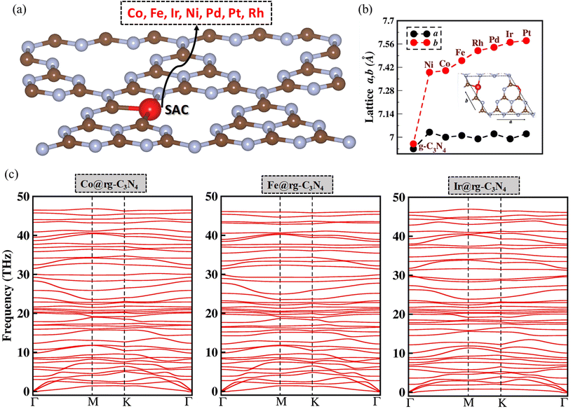
As shown in Fig. 1(a), SACs are modeled by embedding a SA on a N-deficient graphitic carbon nitride (SA@rg-C3N4) monolayer. The metals selected as SACs are Co, Fe, Ir, Ni, Pd, Pt, and Rh as they have been identified as the are most robust SACs based on their high thermodynamic, electrochemical, and thermal stability.58 As depicted in Fig. 1(b), the lattice parameters (a and b for a 1 × 1 unit cell) of the SA@rg-C3N4 systems exhibit a significant increase compared to the pristine (a = 6.93 Å, b = 6.95 Å) and reduced (a = 6.91 Å, b = 5.94 Å) g-C3N4 monolayers. This volume expansion can be attributed to the large van der Waals radii of the SAs incorporated in the manolayer.59 Additionally the optimized configuration and electronic band structure of g-C3N4 and rg-C3N4 monolayers are presented in Fig. S1.† In order to verify the dynamic stability of the SA@rg-C3N4 systems, we conducted an analysis of the phonon dispersion spectra. As illustrated in Fig. 1(c) for Co, Fe, and Ir, and Fig. S2† for the remaining SAs, no noticeable imaginary phonon modes are detected in the spectra, indicating the overall dynamic stability of all seven SA@rg-C3N4 systems.3.1. Adsorption of X8
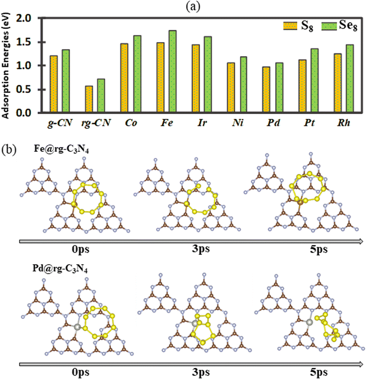
Initially, the adsorption of X8 (with X = S and Se) species is examined on pristine and reduced g-C3N4 as well as SA@rg-C3N4. The calculated adsorption energies are shown in Fig. 2(a), where we observe that the adsorption on all substrates is slightly stronger for Se8 than for S8, even though the overall trends are similar for the two cases. In both cases, the highest adsorption energy is obtained for the Fe catalyst and can be correlated to the shortest bond lengths Fe–S (2.16 Å) and Fe–Se (2.29 Å) among all SAC substrates. With the exception of Pd and Ni, the adsorption energies on the SAC surfaces of both S8 and Se8 structures are notably higher than on pristine and reduced g-C3N4 indicating that the incorporation of SACs can boost the capacity of g-C3N4 to load S and Se active materials. To further elucidate the adsorption mechanism of X8 on the SAC substrates, the charge transfer between the X8 molecules and the substrates is obtained (Fig. S4†). In the case of Pd and Pt catalysts there is a small charge transfer of approximately 0.016 electrons from S8 to the substrate. For Fe, Co, Ir, Ni, and Rh SACs, the charge transfer is also small but occurs in the opposite direction, with approximately in the range from 0.047 to 0.13 electrons transferred from the substrate to S8.In order better understand the adsorption behaviour of S8 and Se8 at the early stages of discharge, AIMD simulations starting at the optimized adsorption configurations on various substrates are performed. After 5 ps, all adsorption configurations of S8 and Se8 on the SAC substrates (except on the Pd SAC) remain intact without any apparent migration or deformation (S8 on the Fe SAC is shown as an example in Fig. 2(b)). However, our calculations indicate that for X8 adsorption on substrates without metal atom catalysts (pristine and reduced g-C3N4 substrates), there is a substantial surface reconstruction and deformation of the X8 molecule. The AIMD snapshots of S8 and Se8 on various substrates are presented in Fig. S5 and S6,† respectively. The apparent migration and rotation of S8 from the hollow cavity shown in Fig. 2(b) can be correlated to the lower adsorption energy of S8 on Pd-based SAC compared to other SA catalysts. Our AIMD calculations indicate that up to 5 ps, the structure of X8 remains almost intact when adsorbed on Fe, Co, Ir, Ni, Pt, and Rh SACs, suggesting that there is no significant occurrence of sulfur or selenium poisoning in these substrates.28,60
3.2. Adsorption of Na–pXs (X = S, Se)
During the discharge process, the interaction of Na cations with the X cathode can generate a series of intermediate compounds from Na2X8 to Na2X (Na2X8, Na2X6, Na2X4, Na2X2, and Na2X). Therefore, we also investigated the interaction between both insoluble species (Na2Xn; n = 1, 2) and soluble species (Na2Xn; n = 4, 6, 8) and the substrates to elucidate the role of the SAC in mitigating the poly-sulfide and selenide shuttle effect in Na–S and Na–Se electrodes. The optimized geometric configurations of all the Na2Xn; n = 1, 2, 4, 6, 8 species are provided in Fig. S7† and the obtained X–X and Na–X bond distance agrees well with previous studies (Table S2†).61–63Fig. 3(a) shows the adsorption energies of Na2Xn (n = 1, 4, 8) species on the surface of pristine (g-C3N4), reduced (rg-C3N4) and seven SA@rg-C3N4 catalysts. The most stable configurations of Na–pSs and Na–pSes adsorbed on various substrates are presented in Fig. S8 and S9,† respectively. The adsorption configurations of Na–pXs for SACs are very similar. Both X and Na atoms contribute to their adsorption via SA–X and Na–N interactions, while the adsorption on pristine and reduced g-C3N4 primarily results only from the interaction between Na and N, which is further confirmed by the charge density analysis in section 3.4. Taking Fe SAC as a representative example, Fig. 3(b) shows that the Fe–S bond length is shortened from 2.18 Å (Na2S8) to 2.16 Å (Na2S), suggesting an enhanced interaction in low-order Na–pXs. Moreover, the adsorption energies of insoluble Na2X on the surface of SACs are in the range of 3.0–3.8 eV, significantly larger than on pristine and reduced g-C3N4 (2.5–2.8 eV), which indicates that the introduction of SAs can enhance the interaction of Na–pXs and rg-C3N4. For comparison, it is worth noting that Na–pSs (Na2Sn; n = 1, 2, 4, 6) exhibit stronger adsorption energies than Na–pSes. However, Na2Se8 exhibits a larger adsorption energies than Na2S8. Among the SACs studied in this work, Fe@rg-C3N4 presents the strongest interaction for both Na–pSs and Na–pSes, with adsorptions energies surpassing numerous previously reported 2D sulfur hosts like graphene,64 MXenes,65 VS2,66 and As2S3.67 Additionally, we have also computed the adsorption energy for Na2X3 species on pristine, reduced g-C3N4, and Fe SAC as shown in Fig. S10.† The observed trend of adsorption strength, with Na2X3 exhibiting greater affinity than Na2X4 and lesser affinity than Na2X, closely mirrors findings reported in the literature for Li2S3.68 It is interesting to compare the Na–pXs binding strengths on these substrates with the interaction energies of these species in commonly used electrolyte solvents such as 1,3-dioxolane (DOL) and 1,2 dimethoxymethane (DME).69 The optimized configurations of DOL and DME with Na–pXs (X = S, Se) are shown in Fig. S11.† The interaction energies (0.58–0.81 eV)65 between Na–pXs and DOL/DME are significantly lower than the adsorption energies (1.65–3.83 eV) of Na–pXs on SACs, suggesting that these SACs can effectively preclude Na–pXs shuttling in Na–S and Na–Se batteries.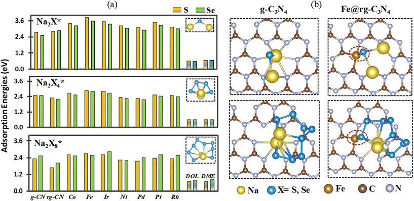 | ||
| Fig. 3 (a) The adsorption energies of Na2Xn (n = 1, 4, 8) adsorbed on SA@rg-C3N4. (b) Geometrical structures of Na2Xn (n = 1, 8) adsorbed on a pristine g-C3N4 and Fe@rg-C3N4 monolayer. | ||
In order to further understand the underlying physical mechanisms governing the interaction between Na–pXs and SAC, we examined the charge transfer of the adsorbed Na–pXs using Bader charge analysis. Our results (see Table S3†) indicate that overall, as sodiation progresses from Na2X8 to Na2X, there is a gradual increase in the amount of charge transferred between the Na–pXs and the substrate. This result indicates that the interaction between each SAC substrate and Na–pXs becomes more robust with increased sodiation, which in turn could explain their greater adsorption affinity for lower Na–pXs. However, when comparing different substrates, we note that the charge transfer between Na–pXs and substrates is, in general, larger in pristine and reduced g-C3N4 than in the SACs substrates. As the binding energies of Na–pXs are significantly larger in the SACs substrates, it is then expected that the SACs substrates increase the covalency of the interactions compared to pristine and reduced g-C3N4.
3.3. Discharging performance of Na–S and Na–Se electrodes
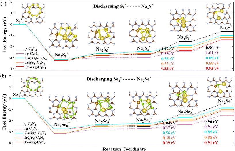
To analyze the discharging performance of the electrodes, we next explore the sulfur and selenium reduction reactions on various g-C3N4 substrates. During the initial discharge process of a Na–S electrode, the solid-phase S8 undergoes a transformation into a series of soluble Na–pSs (Na2Sn; 4 ≤ n ≤ 8), which are subsequently further reduced into insoluble Na–pSs (Na2Sn; 1 ≤ n ≤ 3).70 As discussed previously, the electrochemical reaction mechanisms of Na–Se batteries is similar to that of Na–S batteries, with the formation of Na–pSes as intermediate products and Na2Se as the final discharge product.10 The Gibbs free energy of each intermediate reaction step from S8* to Na2S* and from Se8* to Na2Se* over g-C3N4, rg-C3N4 and SA@rg-C3N4 (with SA = Co, Ir, and Fe) are shown in Fig. 4(a) and (b), respectively. The remaining Gibbs free energy plots for the reduction of Na–pSs and Na–pSes on SA@g-C3N4 (with SA = Rh, Ni, Pd, and Pt) are presented in ESI (Fig. S12†). Following current literature notation, * represents an active site on the catalytic substrate.For both battery systems, the initial step corresponding to the reduction of X8 to Na2X8 is an exothermic reaction regardless of the substrate, indicating the spontaneous nature of this conversion. All the following four reactions steps are endothermic reactions. Our calculations indicate that for g-C3N4, the limiting step corresponds to the transition from Na2X4 to Na2X2, and from Na2X2 to Na2X in the rg-C3N4 substrate. A similar trend of limiting steps is observed in graphene and N-doped graphene for Li–S battery systems.71 For Ir, Co, Fe, and Rh SACs, the last transition from Na2X2 to Na2X is associated with a notably high positive Gibbs free energy barrier compared to other steps indicating the last reaction step as the rate determining (RD) step in the whole process. On the other hand, for SACs containing Ni, Pd, and Pt, the transition from a soluble Na2X4 to an insoluble Na2X2 is found to be the RD step as they present the highest energy barrier. In comparison to Na–S, Na–Se shows a superior reaction kinetics due to the lower RD step barrier for selenium reduction reactions on SACs. The RD step on the surface of SACs is significantly reduced, falling within the range of 0.68 to 1.0 eV, compared to the 1.17 eV and 1.01 eV for pristine g-C3N4 and rg-C3N4, respectively. The obtained RD step barriers for Ni, and Co, Ir, Fe, Rh are lower than for the reported highly active MXenes for Na–S batteries (0.85–1.23 eV)72 and Na–Se batteries (0.80–1.4 eV).61 Overall, the presence of a SA in conjunction with a rg-C3N4 support significantly enhances the discharging performance for the sulfur and selenium reduction reactions.
3.4. Charging performance of Na–S and Na–Se electrodes
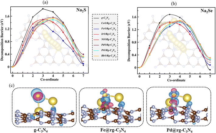
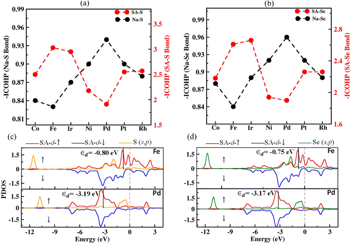
The reaction kinetics during the charging process of Na–S and Na–Se electrodes are primarily governed by the decomposition of Na2S and Na2Se, respectively.11 Therefore, reducing the decomposition barriers of Na2X can significantly enhance the oxidation reaction kinetics and prolong the life cycle of the electrodes. We investigated the decomposition mechanisms of Na2X oxidation (Na2X* → NaX* + Na+ + e−) using the CI-NEB method.48,49 The energy profiles along the optimal reaction pathways for Na2X decomposition are illustrated in Fig. 5(a) and (b). The barriers for the Na2X decomposition on the SACs substrates (1.44–1.56 eV for Na2S and 1.42–1.48 eV for Na2Se) are significantly lower than in both g-C3N4 (1.83 eV for Na2S and 1.68 eV for Na2Se) and rg-C3N4 substrate (2.69 eV for Na2S and 2.53 eV for Na2Se). Furthermore, in Fig. 5(c) we show the charge density difference, defined as Δρ = ρtotal − ρsubstrate − ρNa–pXs,73 where ρtotal, ρsubstrate, and ρNa–pXs stand for the charge densities of the Na–pXs (X = S, Se) molecule adsorbed on the SA@rC3N4 substrate, the SA@rC3N4 substrate, and the isolated Na–pXs molecule, respectively. Fig. 5c, indicates that in the case of pristine g-C3N4, the charge transfer occurs predominantly between Na atoms and the substrate. However, for the SAC substrates, in addition to electron transfer from Na to the substrate, there is also a substantial flow of electrons between S and the metal atom (SA). It is worth noting that the electron transfer is more pronounced in Fe–S than in Pd–S bonds. This increased electron transfer between S and the SA atom can lead to the formation of a S–SA bond and a weakening the Na–S bond.To further investigate the Na2X decomposition mechanism on different SAC substrates, the intensity of Na–X and SA–X on various SACs substrates is evaluated using the Integrated of Crystal Orbital Hamilton Population (ICOHP) analysis.74,75 For clarity, on Fig. 6(a) and (b), we present the negative values of the ICOHP results, –ICOHP, in units of eV per bond. Therefore, larger values of –ICOHP represent stronger inter-atomic interactions. The results shown in Fig. 6(a) and (b) suggest that the strength of both the SA–S and SA–Se bonds is largest for Fe among all other SACs, in agreement with our previous analysis. Conversely, for Na–X bonds, –ICHOP results reveal the opposite trend, i.e., this interaction is weakest for Fe. Additionally, the Na–X bond strength (–ICOHP = 0.95 eV for Na2S and 0.96 eV for Na2Se) is larger in pristine g-C3N4 than in SACs based substrates, in agreement with the decomposition barriers results. The bonding interactions are further explored by plotting the partial density of states (PDOS) for SACs to reveal the electronic states of the SA and X (S, Se) atom. The strength of the SA–X interaction can be correlated to the position of the antibonding state (relative to the Fermi level), where a closer position of the antibonding state to the Fermi level can indicate a stronger SA–X interaction. The d-band model is extensively utilized to elucidate bond formation and reactivity patterns observed in transition metals.76 Results presented in Fig. 6(c) and (d) show that the d-band centers (εd) of Fe are closer to the Fermi level than in other SACs. This proximity results in a stronger interaction between X and Fe, in agreement with the calculated decomposition barriers and binding strengths and the consequent weakening of the Na–X bonds in Na2X. The remaining PDOS for Na2X–SAC (SAC = Co, Ir, Rh, Ni, and Pt) are presented in Fig. S13.†
4. Conclusions
In summary, first-principles calculations are performed to elucidate the charging and discharging kinetics of SACs embedded on reduced g-C3N4 for Na–S and Na–Se electrodes. Through an analysis of Na–pS/Ses adsorption energies, the anchoring functionality of rg-C3N4 monolayer is found to be enhanced through the incorporation of SACs. AIMD simulations are performed to better understand the adsorption behaviour of S8 and Se8 species at the early stages of discharge and indicate no significant occurrence of sulfur or selenium poisoning on the surface of Fe, Co, Ir, Ni, Pt, and Rh SACs.During the discharge process, the Gibbs free energy of the rate-limiting step of S/Se reduction reactions on the SACs is greatly reduced compared to the pristine g-C3N4 and rg-C3N4 surfaces, indicating a higher catalytic activity in the SACs substrates.
For the charging of S and Se electrodes, our results indicate that SACs substrates present a lower decomposition energy barrier for Na2S and Na2Se indicating a faster charging process of Na–S and Na–Se electrodes. These results are further supported by our ICOHP, PDOS, and d-band center analysis of Na2S and Na2Se adsorbed on SAC substrates.
This study offers solutions to the performance limitations caused by the shuttle effect and proposes an effective approach for optimizing single-atom catalysts to enhance the efficiency of sodium–sulfur and sodium–selenium electrodes.
Conflicts of interest
There are no conflicts to declare.Acknowledgements
The authors acknowledge the support of the Automotive Research Center (ARC), Cooperative Agreement W56HZV-19-2-0001 U.S. Army DEVCOM GVSC. DISTRIBUTION STATEMENT A. Approved for public release; distribution is unlimited. OPSEC#8405. We acknowledge the computational resources and services provided by the Institute for Cyber-Enabled Research at Michigan State University.References
- J. Bi, Z. Du, J. Sun, Y. Liu, K. Wang, H. Du, W. Ai and W. Huang, Adv. Mater., 2023, 35, 2210734 CrossRef CAS.
- Y.-K. Liu, C.-Z. Zhao, J. Du, X.-Q. Zhang, A.-B. Chen and Q. Zhang, Small, 2023, 19, 2205315 CrossRef CAS.
- J. Neumann, M. Petranikova, M. Meeus, J. D. Gamarra, R. Younesi, M. Winter and S. Nowak, Adv. Energy Mater., 2022, 12, 2102917 CrossRef CAS.
- N. T. Aristote, X. Deng, K. Zou, X. Gao, R. Momen, F. Li, W. Deng, H. Hou, G. Zou and X. Ji, J. Alloys Compd., 2022, 913, 165216 CrossRef CAS.
- R. Wang, D. Wang, Y. Dong, B. Xie, X. Wu, Q. Wu, S. Zhu, G. Diao and M. Chen, J. Alloys Compd., 2023, 952, 169980 CrossRef CAS.
- L. Jingjing, L. Hongji, H. Qiang and C. Zhe, Prog. Chem., 2022, 34, 857 Search PubMed.
- P. Chen, C. Wang and T. Wang, Mater. Res. Lett., 2022, 10, 691–719 CrossRef CAS.
- P. Hu, F. Xiao, Y. Wu, X. Yang, N. Li, H. Wang and J. Jia, Chem. Eng. J., 2022, 443, 136257 CrossRef CAS.
- G. Wang, Y. Chen, S. Yuan and P. Ge, Molecules, 2022, 27, 5880 CrossRef CAS.
- Z. Huang, P. Jaumaux, B. Sun, X. Guo, D. Zhou, D. Shanmukaraj, M. Armand, T. Rojo and G. Wang, Electrochem. Energy Rev., 2023, 6, 21 CrossRef CAS.
- J. Xu, Y. Qiu, J. Yang, H. Li, P. Han, Y. Jin, H. Liu, B. Sun and G. Wang, Adv. Funct. Mater., 2024, 34, 2306206 CrossRef CAS.
- Z. Wu, X. Lin, J. Zhang, X. Chu, J. Xu, J. Li, Y. Liu, H. Yu, L. Yan and L. Zhang, et al. , Chem. Eng. J., 2023, 454, 140433 CrossRef CAS.
- C. Wu, Y. Lei, L. Simonelli, D. Tonti, A. Black, X. Lu, W.-H. Lai, X. Cai, Y.-X. Wang and Q. Gu, et al. , Adv. Mater., 2022, 34, 2108363 CrossRef CAS.
- Z. Yan, L. Zhao, Y. Wang, Z. Zhu and S.-L. Chou, Adv. Funct. Mater., 2022, 32, 2205622 CrossRef CAS.
- Y. Wang, D. Zhou, V. Palomares, D. Shanmukaraj, B. Sun, X. Tang, C. Wang, M. Armand, T. Rojo and G. Wang, Energy Environ. Sci., 2020, 13, 3848–3879 RSC.
- R. Fang, J. Xu and D.-W. Wang, Energy Environ. Sci., 2020, 13, 432–471 RSC.
- L. Wang, X. Zhang, L. Deng, J. Tang, H. Deng, W. Hu and Z. Liu, ACS Appl. Mater. Interfaces, 2019, 11, 4995–5002 CrossRef CAS.
- J. Ding, H. Zhou, H. Zhang, T. Stephenson, Z. Li, D. Karpuzov and D. Mitlin, Energy Environ. Sci., 2017, 10, 153–165 RSC.
- Q. Xu, H. Liu, W. Du, R. Zhan, L. Hu, S. Bao, C. Dai, F. Liu and M. Xu, Electrochim. Acta, 2018, 276, 21–27 CrossRef CAS.
- X. L. Huang, Y.-X. Wang, S.-L. Chou, S. X. Dou and Z. M. Wang, Energy Environ. Sci., 2021, 14, 3757–3795 RSC.
- M. S. Nahian, R. Jayan and M. M. Islam, ACS Catal., 2022, 12, 7664–7676 CrossRef CAS.
- F. Jin, B. Wang, J. Wang, Y. Wang, Y. Ning, J. Yang, Z. Zhang, P. Liu, Y. Zhou and D. Wang, et al. , Matter, 2021, 4, 1768–1800 CrossRef CAS.
- C. Wang, T. Li, X. Hou, M. Jiang, Q. Zheng and X. Li, Chem. Eng. J., 2023, 451, 139062 CrossRef CAS.
- H. Tian, A. Song, H. Tian, J. Liu, G. Shao, H. Liu and G. Wang, Chem. Sci., 2021, 12, 7656–7676 RSC.
- Z. Du, X. Chen, W. Hu, C. Chuang, S. Xie, A. Hu, W. Yan, X. Kong, X. Wu and H. Ji, et al. , J. Am. Chem. Soc., 2019, 141, 3977–3985 CrossRef CAS.
- Y. Li, J. Wu, B. Zhang, W. Wang, G. Zhang, Z. W. Seh, N. Zhang, J. Sun, L. Huang and J. Jiang, et al. , Energy Storage Mater., 2020, 30, 250–259 CrossRef.
- Z. Zeng, W. Nong, Y. Li and C. Wang, Adv. Sci., 2021, 8, 2102809 CrossRef CAS.
- T. Duan, L. Wang, Z. Ma and Y. Pei, Small, 2023, 19, 2303760 CrossRef CAS.
- I. Choudhuri, P. Bhauriyal and B. Pathak, Chem. Mater., 2019, 31, 8260–8285 CrossRef CAS.
- Z. Chen, J. Zhao, C. R. Cabrera and Z. Chen, Small Methods, 2019, 3, 1800368 CrossRef.
- D. Zeng, W. Xu, W.-J. Ong, J. Xu, H. Ren, Y. Chen, H. Zheng and D.-L. Peng, Appl. Catal., B, 2018, 221, 47–55 CrossRef CAS.
- W. Sun, Z. Song, Z. Feng, Y. Huang, Z. J. Xu, Y.-C. Lu and Q. Zou, Nano–Micro Lett., 2022, 14, 222 CrossRef CAS.
- M. Jyothirmai, D. Roshini, B. M. Abraham and J. K. Singh, ACS Appl. Energy Mater., 2023, 6, 5598–5606 CrossRef CAS.
- H. Niu, X. Wan, X. Wang, C. Shao, J. Robertson, Z. Zhang and Y. Guo, ACS Sustainable Chem. Eng., 2021, 9, 3590–3599 CrossRef CAS.
- Y. Lu, H. Wang, P. Yu, Y. Yuan, R. Shahbazian-Yassar, Y. Sheng, S. Wu, W. Tu, G. Liu and M. Kraft, et al. , Nano Energy, 2020, 77, 105158 CrossRef CAS.
- S. He, J. Yang, S. Liu, X. Wang, X. Che, M. Wang and J. Qiu, Chem. Eng. J., 2023, 454, 140202 CrossRef CAS.
- W.-W. Liu, S.-T. Niu, Z.-Q. Xu, R. Zou, C.-Y. Cui, Y.-X. Lei, X.-B. Zhang and F. Ran, Appl. Surf. Sci., 2023, 609, 155327 CrossRef CAS.
- P. Zhou, F. Lv, N. Li, Y. Zhang, Z. Mu, Y. Tang, J. Lai, Y. Chao, M. Luo and F. Lin, et al. , Nano Energy, 2019, 56, 127–137 CrossRef CAS.
- X. Chen, X. Zhao, Z. Kong, W.-J. Ong and N. Li, J. Mater. Chem. A, 2018, 6, 21941–21948 RSC.
- G. Kresse and J. Furthmüller, Phys. Rev. B: Condens. Matter Mater. Phys., 1996, 54, 11169 CrossRef CAS.
- G. Kresse and J. Furthmüller, Comput. Mater. Sci., 1996, 6, 15–50 CrossRef CAS.
- J. P. Perdew, K. Burke and M. Ernzerhof, Phys. Rev. Lett., 1996, 77, 3865 CrossRef CAS.
- P. E. Blöchl, Phys. Rev. B: Condens. Matter Mater. Phys., 1994, 50, 17953 CrossRef.
- S. Grimme, J. Antony, S. Ehrlich and H. Krieg, J. Chem. Phys., 2010, 132, 154104 CrossRef.
- N. Yamsang, J. Sittiwong, P. Srifa, B. Boekfa, M. Sawangphruk, T. Maihom and J. Limtrakul, Appl. Surf. Sci., 2021, 565, 150378 CrossRef CAS.
- Y. Cheng, Y. Dou, D. Kan, Y. Wang and Y. Wei, Appl. Surf. Sci., 2023, 610, 155481 CrossRef CAS.
- G. D. Fao and J.-C. Jiang, Mol. Catal., 2022, 526, 112402 CrossRef CAS.
- G. Henkelman, B. P. Uberuaga and H. Jónsson, J. Chem. Phys., 2000, 113, 9901–9904 CrossRef CAS.
- G. Henkelman and H. Jónsson, J. Chem. Phys., 2000, 113, 9978–9985 CrossRef CAS.
- W. Tang, E. Sanville and G. Henkelman, J. Phys.: Condens. Matter, 2009, 21, 084204 CrossRef CAS.
- A. Togo, F. Oba and I. Tanaka, Phys. Rev. B: Condens. Matter Mater. Phys., 2008, 78, 134106 CrossRef.
- A. Togo and I. Tanaka, Scr. Mater., 2015, 108, 1–5 CrossRef CAS.
- S. Maintz, V. L. Deringer, A. L. Tchougréeff and R. Dronskowski, J. Comput. Chem., 2016, 37, 1030–1035 CrossRef CAS.
- V. Wang, N. Xu, J.-C. Liu, G. Tang and W.-T. Geng, Comput. Phys. Commun., 2021, 267, 108033 CrossRef CAS.
- K. Momma and F. Izumi, J. Appl. Crystallogr., 2011, 44, 1272–1276 CrossRef CAS.
- Y. Zhao and J. Zhao, Appl. Surf. Sci., 2017, 412, 591–598 CrossRef CAS.
- L. Song, M. Zhang and J. Guo, Chem. Phys. Lett., 2021, 777, 138711 CrossRef CAS.
- M. Jakhar, Y. Ding, B. D. Fahlman and V. Barone, Nano Express, 2024, 5, 015028 CrossRef.
- S. S. Batsanov, Inorg. Mater., 2001, 37, 871–885 CrossRef CAS.
- X. Song, D. Tian, Y. Qiu, X. Sun, B. Jiang, C. Zhao, Y. Zhang, L. Fan and N. Zhang, Energy Storage Mater., 2021, 41, 248–254 CrossRef.
- C. Wei, M. Ge, T. Fang, X. Tang and X. Liu, Phys. Chem. Chem. Phys., 2023, 25, 24948–24959 RSC.
- N. Li, Y. Zhan, H. Wu, J. Fan and J. Jia, Nanoscale, 2022, 14, 17027–17035 RSC.
- M. Sajjad, T. Hussain, N. Singh and J. A. Larsson, Langmuir, 2020, 36, 13104–13111 CrossRef CAS.
- R. Jayan and M. M. Islam, J. Phys. Chem. C, 2021, 125, 4458–4467 CrossRef CAS.
- N. Li, Y. Zhan, H. Wu, J. Fan and J. Jia, Nanoscale, 2023, 15, 2747–2755 RSC.
- R. Jayan and M. M. Islam, ACS Appl. Mater. Interfaces, 2021, 13, 35848–35855 CrossRef CAS.
- T. Kaewmaraya, T. Hussain, R. Umer, Z. Hu and X. Zhao, Phys. Chem. Chem. Phys., 2020, 22, 27300–27307 RSC.
- S. Mukherjee, L. Kavalsky, K. Chattopadhyay and C. V. Singh, Nanoscale, 2018, 10, 21335–21352 RSC.
- Y. Liu, Y. Elias, J. Meng, D. Aurbach, R. Zou, D. Xia and Q. Pang, Joule, 2021, 5, 2323–2364 CrossRef CAS.
- H. Liu, W.-H. Lai, Q. Yang, Y. Lei, C. Wu, N. Wang, Y.-X. Wang, S.-L. Chou, H. K. Liu and S. X. Dou, Nano–Micro Lett., 2021, 13, 121 CrossRef CAS.
- G. Zhou, S. Zhao, T. Wang, S.-Z. Yang, B. Johannessen, H. Chen, C. Liu, Y. Ye, Y. Wu and Y. Peng, et al. , Nano Lett., 2019, 20, 1252–1261 CrossRef.
- M. S. Nahian, R. Jayan, T. Kaewmaraya, T. Hussain and M. M. Islam, ACS Appl. Mater. Interfaces, 2022, 14, 10298–10307 CrossRef CAS.
- Z. Yi, F. Su, L. Huo, G. Cui, C. Zhang, P. Han, N. Dong and C. Chen, Appl. Surf. Sci., 2020, 503, 144446 CrossRef CAS.
- V. L. Deringer, A. L. Tchougréeff and R. Dronskowski, J. Phys. Chem. A, 2011, 115, 5461–5466 CrossRef CAS.
- M. Tachibana, K. Yoshizawa, A. Ogawa, H. Fujimoto and R. Hoffmann, J. Phys. Chem. B, 2002, 106, 12727–12736 CrossRef CAS.
- S. Bhattacharjee, U. V. Waghmare and S.-C. Lee, Sci. Rep., 2016, 6, 35916 CrossRef CAS.
Footnote |
| † Electronic supplementary information (ESI) available: Phonon spectrum curves for SA@rg-C3N4; charge transfer and AIMD plot for the X8 (X = S, Se) molecules; the optimized geometric configurations of Na–pXs (X = S, Se); geometric configurations of electrolyte solvent (DOL and DME); Gibbs free energy profile for sulfur/selenium reduction reactions (S/SeRRs); partial density of states (PDOS) of Na2X–SA. See DOI: https://doi.org/10.1039/d4nr01134a |
| This journal is © The Royal Society of Chemistry 2024 |

