 Open Access Article
Creative Commons Attribution 3.0 Unported Licence
Important factors for effective use of carbon nanotube matrices in electrochemical capacitor hybrid electrodes without binding additives†
Ricardo
Quintero
ab,
Dong Young
Kim
a,
Kei
Hasegawa
a,
Yuki
Yamada
b,
Atsuo
Yamada
b and
Suguru
Noda
*a
aDepartment of Applied Chemistry, Waseda University, 3-4-1 Okubo, Shinjuku-ku, Tokyo, 169-8555, Japan. E-mail: noda@waseda.jp; Fax: +81 352862769; Tel: +81 352862769
bDepartment of Chemical System Engineering, The University of Tokyo, 7-3-1 Hongo, Bunkyo-ku, Tokyo 113-8656, Japan
First published on 29th January 2015
Abstract
Various capacitive particles are currently available for use in electrochemical capacitors, but their electrical conductivities are typically low and require enhancement. Carbon nanotube (CNT) matrices can be used to fabricate self-supporting electrodes without binding or conducting additives. Herein, liquid dispersion and subsequent vacuum filtration were used to prepare thick (∼100 μm) hybrid electrodes of activated carbon (AC) and CNTs. Factors including CNT type, AC particle size, solvent, and surfactant strongly affected the capacitance and rate performance of the hybrid electrodes. Different solvents and types of CNTs were best suited for pure CNT electrodes and AC–CNT hybrid electrodes; single-wall CNTs (SWCNTs) with a strong dispersant produced CNT electrodes with the best performance among pure CNT electrodes. Meanwhile, few-wall CNTs (FWCNTs) with a weak dispersant produced AC–CNT hybrid electrodes with the best performance among hybrid electrodes. Addition of 10 wt% FWCNTs to AC yielded a self-supporting hybrid electrode with improved performance (132 F g−1, 58 F cm−3, 0.70 F cm−2 at 100 mV s−1) compared with that of a conventional AC electrode with conducting and binding additives (74 F g−1, 26 F cm−3, 0.60 F cm−2 at 100 mV s−1), and a pure electrode of expensive SWCNTs (52 F g−1, 26 F cm−3, 0.26 F cm−2 at 100 mV s−1).
Introduction
Electrochemical capacitors (ECs), also known as supercapacitors, are receiving increasing attention as possible storage systems for electrical energy. Extensive research to improve the performance of ECs has been undertaken, including fabrication of active materials with higher energy densities, electrolytes with wider voltage windows and hybrid systems using Faradaic reactions.1 Activated carbon (AC) is the material of choice for electric double layer (EDL) capacitors because of its large capacitance, long cycling life, low cost and good processability. The high specific surface area (SSA) of 1000–3500 m2 g−1 (ref. 2) and the porous structure of AC allow charge storage at the electrode/electrolyte interface, with a capacitance of 10 μF cm−2 (ref. 3). Conventional electrodes are made from AC particles using conductive additives and polymeric binders that are chemically stable at given electrochemical potentials. Other types of widely investigated capacitive particle are transition metal oxides, which can store considerable electrical charge through fast and reversible Faradaic redox reactions. Capacitances as high as 768 F g−1 for ruthenium oxide4 and 265–320 F g−1 for manganese oxide5,6 have been achieved. However, some of these materials are limited by low surface area and electrical conductivity, making their efficient use difficult.Carbon nanotubes (CNTs) possess high tensile strength, flexibility, electrical conductivity and reasonably high SSA. Pristine CNT electrodes exhibit excellent rate performance, i.e., a low capacitance reduction ratio at high scan rates, and moderate capacitances.7,8 Single-wall CNTs (SWCNTs) have the highest SSA for their exterior surface among CNTs, of up to 1320 m2 g−1. Pure SWCNT electrodes exhibit excellent rate performance,9 although their cost of up to ∼1000 USD per g limits their practical application. CNTs have also been used in electrodes as current-collecting substrates for other active materials such as conductive polymers and metal oxides,10–14 and with high-voltage window electrolytes.15,16 However, the strong van der Waals interactions in SWCNTs17,18 leads to formation of bundles and disordered networks, which makes it difficult to realise their optimum mechanical and electronic properties.19,20
Chemical vapour deposition (CVD) is suitable for producing large amounts of CNTs. Fluidised-bed CVD (FB-CVD), in which catalyst-supported powders are uniformly heated and mixed with a reactant gas, is especially suitable to produce CNTs. Multi-wall CNTs (MWCNTs) are mass produced by FB-CVD at amounts of several hundred tons annually per plant and production cost of ∼100 USD per kg.21 We previously developed FB-CVD, and realised the continuous and batch production of sub-millimetre-long few-wall CNTs (FWCNTs)22,23 and SWCNTs,24 respectively. FWCNTs offer advantages over SWCNTs in terms of cost, ease of manipulation, and capability of functionalization by oxidation while retaining conductivity. The flexibility and high aspect ratio of FWCNTs can yield self-supporting films, and positive electrodes for lithium batteries have been developed using oxidised FWCNTs.25
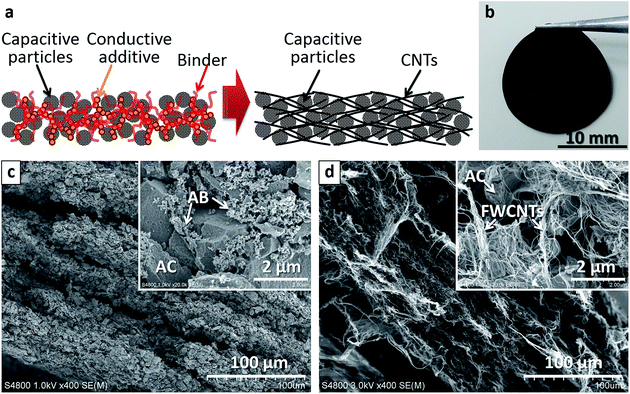
Combining CNTs with AC in hybrid electrodes has been explored to increase the conductivity of conventional electrodes, and as a replacement for conventional conductive additives.26–29 Self-supporting hybrid films of AC and CNTs have been reported,30–32 which may produce light-weight, high-capacity electrodes without using metal collectors, thus avoiding their contribution to the weight of the device.33 In the current study, we use sub-millimetre-long FWCNTs22,23 and SWCNTs24 as matrix to hold capacitive particles for ECs. Pure CNT electrodes and AC–CNT hybrid electrodes are fabricated without binders, and their performance is compared with that of conventional hybrid electrodes of AC with the conductive additive acetylene black (AB) and binder polytetrafluoroethylene (PTFE) (Fig. 1a). A photo of a typical AC–CNT hybrid film (Fig. 1b) shows its self-supporting and flexible nature without the aid of binders. Both conventional and proposed electrodes had a layered structure parallel to the film surface (Fig. 1c and d). In the latter electrode (Fig. 1d), AC particles distributed uniformly and individual AC particles were covered well with numerous CNTs. When we consider practical devices, volumetric and areal capacitances are very important in addition to gravimetric capacitances. Thus we worked on thick electrodes (∼200 μm as-prepared and ∼100 μm after pressing) and discussed these capacitance values. The effects of factors including the types of solvent and surfactant used to disperse AC and CNTs, AC particle size, SSA of AC, and CNT loading on electrode performance are investigated systematically to achieve hybrid EC electrodes with enhanced capacity and conductivity.
Experimental
Electrode preparation
FWCNTs and SWCNTs were fabricated by FB-CVD using C2H2 as a carbon source as reported previously.22–24 The CNTs were highly pure as produced (99 wt% or higher), so we used them without any purification. To prepare pure CNT electrodes, SWCNTs and FWCNTs were dispersed in three different solvents: H2O with sodium dodecylbenzenesulphonate (SDBS) surfactant (0.5 wt%), N-methylpyrrolidone (NMP) and ethanol (EtOH). Dispersion was carried out using a bath-type 600-W sonicator for 30 min, with a cooling unit to maintain the temperature at 20 °C. Electrodes were formed by vacuum filtration of the dispersions through PTFE membrane filters with a pore size of 5 μm. To remove residual SDBS, electrodes were rinsed with boiling distilled water, soaked for 10 min in 60 wt% HNO3 at room temperature, and finally rinsed with boiling distilled water. Residual EtOH and NMP were removed by drying the electrodes at 150 and 205 °C, respectively.To prepare AC–CNT hybrid electrodes, different amounts of CNTs were mixed with AC particles in different solvents. Two different types of AC were used: activated charcoal untreated powder (100–400 mesh, 1001 m2 g−1, Sigma-Aldrich, St. Louis, MO, USA) and YP80-F AC (5–20 μm diameter, 2042 m2 g−1, Kuraray Chemical Co., Tokyo, Japan), which are referred to as AC1000 and AC2000, respectively. Different ratios of AC and CNTs were added to the dispersing agents H2O–SDBS (0.5 wt%), NMP and EtOH to give mixtures with 0.1 mg of carbon material per mL of solution. Dispersion of each mixture was carried out using a bath-type 600-W sonicator for 30 min at 20 °C. Electrodes were obtained by vacuum filtration of the dispersions through PTFE membrane filters with a pore size of 5 μm and subsequent drying at 150 °C in air for ∼3 h. Residual SDBS, EtOH, and NMP were removed in the same manner as for the pure CNT electrodes. Most electrodes were ∼200 μm thick as prepared and ∼100 μm thick after pressing at 10 MPa.
To observe the dispersion states of CNTs in different dispersants, the dispersions were spin-coated at 4000 rpm for 30 s on Si wafers that had been pretreated in piranha solution (96 wt% sulphuric acid and 30 wt% hydrogen peroxide with a volume ratio of 70![[thin space (1/6-em)]](https://www.rsc.org/images/entities/char_2009.gif) :
:![[thin space (1/6-em)]](https://www.rsc.org/images/entities/char_2009.gif) 30) for 10 min.
30) for 10 min.
Electrode characterization
Microstructures of the CNT-based self-supporting films were analysed by scanning electron microscopy (SEM, Hitachi S-4800, Tokyo, Japan). The CNTs spin-coated on Si wafers were also analysed by SEM to evaluate their dispersion state. Sheet resistance was determined by the four-point probe method. SSAs were calculated by Brunauer–Emmett–Teller (BET) analysis of nitrogen adsorption isotherms measured at 77 K (BEL Japan Belsorp-28SA, Osaka, Japan or Quantachrome Instruments Autosorb 1C, Boynton Beach, FL, USA). Elemental composition was determined using a wavelength-dispersive X-ray fluorescence spectrometer (XRF, Rigaku ZSX Primus II, Akishima, Japan).Three-electrode cells were used to perform cyclic voltammetry (CV), electrochemical impedance spectroscopy (EIS) and galvanostatic charge–discharge measurements with a potentiostat (Bio-Logic VMP3, France). The three-electrode cell consisted of either a pure CNT or AC–CNT film (sandwiched with two Ti meshes and pressed at 10 MPa) as the working electrode, Pt-mesh counter electrode and Ag/AgCl reference electrode (in saturated aqueous NaCl). The electrolyte was aqueous 1 M H2SO4. EIS was performed over the frequency range of 100 kHz to 10 mHz at a constant potential of 0.0 V vs. Ag/AgCl, and the amplitude of the excitation signal was ±10 mV.
Results and discussion
Performance of pure SWCNT and FWCNT electrodes
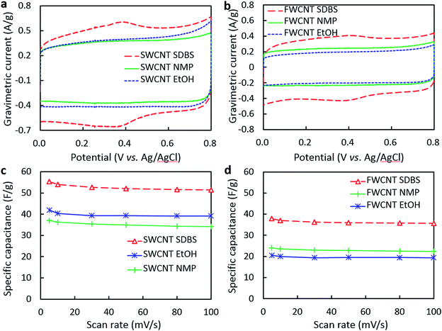
The dispersibility and cost of CNTs are important considerations in their practical application, so the properties of different types of CNTs are compared in this section. The CVs in Fig. 2 provide information about the rate capability of the SWCNT and FWCNT electrodes, and the influence of different dispersion solvents. The gravimetric current of the pure SWCNT electrodes (Fig. 2a and c) was higher than that of the pure FWCNT ones (Fig. 2b and d), but the shapes of the CVs (Fig. 2a and b) were similar for the electrodes prepared from dispersions of the same solvents. The CVs of the electrodes processed in NMP and EtOH exhibited regular rectangular shapes without any apparent peaks (Fig. 2a and b), similar to those of an ideal capacitor, where electric charge (q) is proportional to applied voltage (V), and the constant of proportionality is capacitance (C); that is, q = CV. High electrical conductivity and the absence of parasitic reactions translate into rectangular CVs, which indicate uniform ion diffusion and good rate performance.34 The electrodes processed in H2O–SDBS exhibited a broad peak at around 0.4 V in the forward and reverse scans (Fig. 2a and b), consistent with a contribution from pseudocapacitance in addition to the predominant EDL capacitance. This peak may result from the acid rinsing of the electrode to remove SDBS. The immersion time of the electrode in acid was sufficient to form oxygen functionalities like –COOH, –OH, and![[double bond splayed left]](https://www.rsc.org/images/entities/char_e009.gif) C
C![[double bond, length as m-dash]](https://www.rsc.org/images/entities/char_e001.gif) O on the CNT surface.8,35 The electrode processed in H2O–SDBS solution had a higher oxygen content (4.17 wt%) than those of the electrodes processed in NMP (2.03 wt%) and EtOH (1.47 wt%) (see ESI, Table S1†), confirming that rinsing with acid resulted in the presence of additional functional groups. Thus soaking in HNO3 had two different effects: removing SDBS to increase the conductivity and the surface area available for EDL capacitance of the CNT networks, and modifying the carbon surface with electrochemically active oxygen-containing groups. The contributions from specific functionalities on carbon surfaces to capacitance has been widely reported, including those from N- and S-based groups,36–41 although N and S contents were low in our samples.
O on the CNT surface.8,35 The electrode processed in H2O–SDBS solution had a higher oxygen content (4.17 wt%) than those of the electrodes processed in NMP (2.03 wt%) and EtOH (1.47 wt%) (see ESI, Table S1†), confirming that rinsing with acid resulted in the presence of additional functional groups. Thus soaking in HNO3 had two different effects: removing SDBS to increase the conductivity and the surface area available for EDL capacitance of the CNT networks, and modifying the carbon surface with electrochemically active oxygen-containing groups. The contributions from specific functionalities on carbon surfaces to capacitance has been widely reported, including those from N- and S-based groups,36–41 although N and S contents were low in our samples.
C of the electrodes was calculated from the CVs using the expression:
 | (1) |
Effect of dispersant on the performance of AC–SWCNT and AC–FWCNT hybrid electrodes
Next, equal weights of AC1000 and CNTs were used to prepare hybrid electrodes to examine the effect of dispersant on the performance of AC–CNT hybrid electrodes. The CVs of the hybrid electrodes processed in EtOH and NMP exhibited a rectangular shape (Fig. 3a and b). The electrodes processed in H2O–SDBS had non-rectangular CVs with a broad peak centred at 0.4 V resulting from the contribution of redox reactions consistent with oxidation of the carbon surface during rinsing with HNO3.8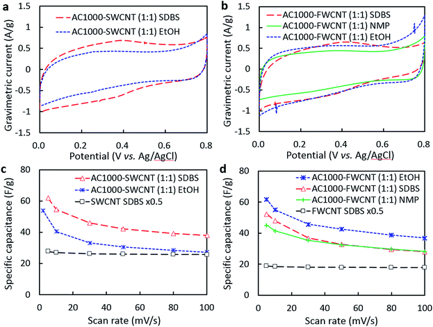 | ||
Fig. 3 (a and b) CVs of AC1000–SWCNT (1![[thin space (1/6-em)]](https://www.rsc.org/images/entities/char_2009.gif) : :![[thin space (1/6-em)]](https://www.rsc.org/images/entities/char_2009.gif) 1) and AC1000–FWCNT (1 1) and AC1000–FWCNT (1![[thin space (1/6-em)]](https://www.rsc.org/images/entities/char_2009.gif) : :![[thin space (1/6-em)]](https://www.rsc.org/images/entities/char_2009.gif) 1) electrodes processed in H2O–SDBS, NMP and EtOH (scan rate = 10 mV s−1). (c and d) Dependence of capacitance on scan rate of the hybrid electrodes. Plots for pure CNT electrodes (from Fig. 2c and d) are also shown for comparison. Specific capacitance values shown for pure CNT electrodes have been halved to clarify the contribution from AC in the hybrid electrodes. 1) electrodes processed in H2O–SDBS, NMP and EtOH (scan rate = 10 mV s−1). (c and d) Dependence of capacitance on scan rate of the hybrid electrodes. Plots for pure CNT electrodes (from Fig. 2c and d) are also shown for comparison. Specific capacitance values shown for pure CNT electrodes have been halved to clarify the contribution from AC in the hybrid electrodes. | ||
The rate capability plots in Fig. 3c and d provide insight into the effect of each dispersant on the porous structure of the hybrid electrodes. The AC–SWCNT electrode processed in H2O–SDBS had higher specific capacitance than that processed in EtOH (Fig. 3c). In particular, the specific capacitance of the latter approached that of the pure SWCNT electrode containing the same weight of CNTs, showing the diminishing contribution of AC to specific capacitance at high scan rates. It is probable that SWCNTs were not effectively dispersed in EtOH, resulting in poor electrical contact with AC particles. Interestingly, the opposite result was obtained for AC–FWCNT electrodes; the electrode processed in EtOH exhibited the highest specific capacitance while that processed in H2O–SDBS did the lowest one among the AC1000–FWCNT electrodes. All of the electrodes exhibited higher specific capacitances than that of the pure FWCNT electrode containing the same weight of CNTs at high scan rates, suggesting sufficient electrical contact with AC particles. However, the specific capacitance of the AC–FWCNT electrodes was higher for those processed in EtOH than the other solvents, suggesting that SDBS and NMP were adsorbed in the pores of AC, which decreases the electrolyte-accessible area of AC. From a practical aspect, it is encouraging that similar specific capacitance and rate performance were achieved for the AC–FWCNT electrode processed in EtOH to those of the AC–SWCNT electrode processed in H2O–SDBS. However, the factors affecting the enhancement of specific capacitance by hybridization with AC should be different for these two electrodes, so next we examined the dispersibility of CNTs and adsorption of dispersants in AC pores.
The dispersion states of CNTs in different solvents were examined by spin-coating the dispersions on Si wafers and observing them by SEM (Fig. 4). The low-magnification images show the aggregate structure while the inset high-magnification images show the bundle structure of the CNTs. These SEM images reveal differences in the dispersion states of SWCNTs and FWCNTs. SWCNTs formed small (∼5 μm), medium (∼10 μm), and large (≫10 μm) aggregates in H2O–SDBS, NMP, and EtOH, respectively. In particular, EtOH-processed SWCNTs formed thick bundles composed of many SWCNTs (inset of Fig. 4e), confirming their poor dispersibility in EtOH. In contrast, FWCNTs adopted a similar dispersion state of large aggregates (>10 μm) of thin bundles regardless of solvent, revealing their good dispersibility. These images confirm that mild dispersants, which do not obstruct the pores of AC, can be used for FWCNTs.
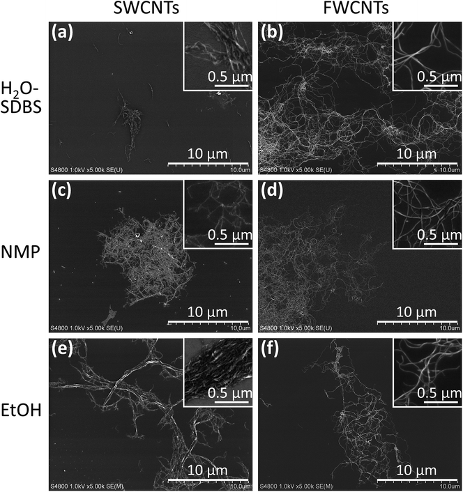 | ||
| Fig. 4 SEM images of dispersions of (a, c and e) SWCNTs and (b, d and f) FWCNTs in (a and b) H2O–SDBS, (c and d) NMP, and (e and f) EtOH spin-coated on Si wafers. | ||
The electrical conductivity and SSA of electrodes processed in H2O–SDBS and EtOH are presented in Table 1. SDBS appeared to be adsorbed within the pores of AC1000, even after successive rinsing with boiling water and HNO3. This decreased the available surface area of the AC1000–FWCNT electrode to 357 m2 g−1, compared with 528 m2 g−1 for the electrode processed in EtOH. The SSA for the electrode processed in EtOH is still smaller than the expected value of 715 m2 g−1 for a simple AC1000–FWCNT mixture, so EtOH reduces the available surface of AC to some extent. A higher bulk conductivity (σ) of 48.8 S cm−1 was achieved using electrodes processed in H2O–SDBS than in EtOH. This was because of the better dispersion and network formation of CNTs in H2O–SDBS than in EtOH, and the effective CNT doping that occurred during acid rinsing. EtOH can disperse both AC and FWCNTs to a certain extent, with σ = 36.6 S cm−1 for the AC1000–FWCNT electrode processed in EtOH. The effect of dispersant on the available surface area of capacitive particles is an important consideration when aiming to maximise charge storage. Different results were obtained for the pure CNT and hybrid AC–CNT electrodes. SWCNTs exhibited better performance in pure CNT electrodes than FWCNTs because of their higher conductivity and SSA. Conversely, FWCNTs yielded better performance than SWCNTs when hybridised with AC because of their good dispersibility in EtOH, which did not obstruct the pores in AC too much. Thus, EtOH and FWCNTs were used in the following study of AC–CNT hybrid electrodes.
| AC1000 | FWCNT (EtOH) | AC1000–FWCNT (1![[thin space (1/6-em)]](https://www.rsc.org/images/entities/char_2009.gif) : :![[thin space (1/6-em)]](https://www.rsc.org/images/entities/char_2009.gif) 1) (H2O–SDBS) 1) (H2O–SDBS) |
AC1000–FWCNT (1![[thin space (1/6-em)]](https://www.rsc.org/images/entities/char_2009.gif) : :![[thin space (1/6-em)]](https://www.rsc.org/images/entities/char_2009.gif) 1) (EtOH) 1) (EtOH) |
|
|---|---|---|---|---|
| SSA (m2 g−1) | 1001 | 428 | 357 | 528 |
| σ (S cm−1) | N.A. | 85.7 | 48.8 | 36.6 |
Effect of AC particle size on electrochemical capacitance
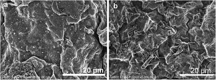
To obtain different particle sizes of capacitive AC, AC1000 was ultrasonically treated in EtOH in a bath-type ultrasonicator for 16 h. The resulting material is referred to as US AC1000. The cavitation energy during ultrasonication can disperse and fracture solids,42 and an overall reduction in AC particle size from 20–100 to 10–60 μm was observed following ultrasonic treatment (Fig. 5).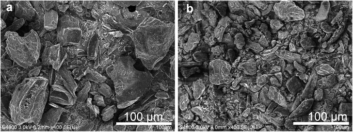 | ||
| Fig. 5 SEM images of (a) as-received AC1000 and (b) AC1000 after ultrasonication for 16 h (US AC1000). | ||
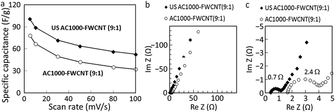
The FWCNT loading of the electrode was reduced to increase the amount of capacitive AC to 90 wt%. The electrical conductivities of the corresponding AC1000–FWCNT and US AC1000–FWCNT electrodes were 5.17 and 8.73 S cm−1, respectively, suggesting less disturbance of the electrical conduction pathway by smaller US AC1000 particles than by larger ones. The rate performance of both hybrid electrodes is illustrated in Fig. 6a. An increase in the specific capacitance of 22–39%, and improvement in rate performance were observed for the hybrid electrodes with smaller particles, i.e., US AC1000 compared with those of the electrodes with larger ones.
EIS measurements were carried out to further analyse the resistance of the hybrid electrodes using Nyquist plots, which are depicted in Fig. 6b and c. Information about electrolyte, contact and ion-diffusion resistances can be obtained from these plots. In general, a straight line along the imaginary axis is related to ideal EDL capacitance, and in real capacitors with a series resistance, this line has a finite slope, representing the diffusive resistivity of the electrolyte within the pores of the electrode.43 The US AC1000–FWCNT electrode exhibited a lower equivalent series resistance (ESR) than the AC1000–FWCNT one. Zhang et al.44 evaluated the effect of particle size of AC with a high surface area on electrode performance using conventional EC electrode architecture. They obtained higher rate performance for smaller AC particles mainly due to the low intraparticle resistivity and rapid diffusion of ions within pores of AC particles. Although the solution series resistance and polarization resistance cannot be reduced by the AC particle size, the use of smaller AC particles is also effective at enhancing the rate performance of our AC–FWCNT hybrid electrodes.
Effect of SSA and particle size of AC on electrode performance
AC1000 and AC2000 particles were used to determine the effects of the particle size and SSA of capacitive particles on the performance of hybrid electrodes. As-received AC2000 had a much smaller average particle size of 10–15 μm than that of as-received AC1000 (20–100 μm). The SEM images in Fig. 7 show the morphologies of the prepared electrodes, in which the size and shape of the AC particles can be distinguished. The mechanically robust matrix of compact interwoven FWCNTs bound to the AC particles, with their surface being partially or completely covered by the flexible FWCNTs.The SSA and conductivity for the AC–FWCNT (9![[thin space (1/6-em)]](https://www.rsc.org/images/entities/char_2009.gif) :
:![[thin space (1/6-em)]](https://www.rsc.org/images/entities/char_2009.gif) 1) hybrid films are summarised in Table 2. BET analyses indicated that the SSA of AC2000 was twice that of AC1000, and almost five times that of FWCNTs (Table 2). The BET SSAs of the AC–FWCNT hybrids included the individual contributions of both AC and CNTs. Although the SSA of AC2000–FWCNT of 1783 m2 g−1 is slightly smaller than the simple sum of the SSAs of AC2000 (0.9 g) and FWCNT (0.1 g) of 1881 m2 g−1, EtOH only reduced the available surface by small amount as expected. The conductivity of the AC2000–FWCNT electrode was 10.1 S cm−1, higher than that of the AC1000–FWCNT electrode of 5.17 S cm−1. The smaller AC2000 particles disturbed electrical conduction less than the larger AC1000 particles, in a similar manner to the small US AC1000 particles.
1) hybrid films are summarised in Table 2. BET analyses indicated that the SSA of AC2000 was twice that of AC1000, and almost five times that of FWCNTs (Table 2). The BET SSAs of the AC–FWCNT hybrids included the individual contributions of both AC and CNTs. Although the SSA of AC2000–FWCNT of 1783 m2 g−1 is slightly smaller than the simple sum of the SSAs of AC2000 (0.9 g) and FWCNT (0.1 g) of 1881 m2 g−1, EtOH only reduced the available surface by small amount as expected. The conductivity of the AC2000–FWCNT electrode was 10.1 S cm−1, higher than that of the AC1000–FWCNT electrode of 5.17 S cm−1. The smaller AC2000 particles disturbed electrical conduction less than the larger AC1000 particles, in a similar manner to the small US AC1000 particles.
| AC2000 | FWCNT (EtOH) | AC1000–FWCNT (9![[thin space (1/6-em)]](https://www.rsc.org/images/entities/char_2009.gif) : :![[thin space (1/6-em)]](https://www.rsc.org/images/entities/char_2009.gif) 1) (EtOH) 1) (EtOH) |
AC2000–FWCNT (9![[thin space (1/6-em)]](https://www.rsc.org/images/entities/char_2009.gif) : :![[thin space (1/6-em)]](https://www.rsc.org/images/entities/char_2009.gif) 1) (EtOH) 1) (EtOH) |
|
|---|---|---|---|---|
| SSA (m2 g−1) | 2042 | 428 | 857 | 1783 |
| σ (S cm−1) | N.A. | 85.7 | 5.17 | 10.1 |
The CVs of the AC1000–FWCNT (9![[thin space (1/6-em)]](https://www.rsc.org/images/entities/char_2009.gif) :
:![[thin space (1/6-em)]](https://www.rsc.org/images/entities/char_2009.gif) 1) and AC2000–FWCNT (9
1) and AC2000–FWCNT (9![[thin space (1/6-em)]](https://www.rsc.org/images/entities/char_2009.gif) :
:![[thin space (1/6-em)]](https://www.rsc.org/images/entities/char_2009.gif) 1) electrodes in Fig. 8 show the change in electrical current of the electrodes at different potentials. These voltammograms suggest that there are important differences in the capacitance mechanisms and rate performances of these electrodes. The AC1000–FWCNT electrode exhibited no visible peaks, and its CVs were irregular, especially in the last scan segments (0.0–0.1 V and 0.7–0.8 V). The AC2000–FWCNT electrode exhibited broad peaks centred at 0.4 and 0.2 V in the forward and reverse scans, respectively, in addition to the overall rectangular shape. These peaks were consistent with fast redox reactions of functional groups, although we did not treat the AC2000–FWCNT hybrid with nitric acid in this experiment. The source of these redox peaks may be the evolution of activated oxygen species adsorbed on the carbon electrode surface, and the subsequent formation of quinoidal species,45 although further investigation is needed to clarify their origin. Elemental characterization of AC2000–FWCNT electrodes prepared using different dispersants is shown in Table S2† for reference.
1) electrodes in Fig. 8 show the change in electrical current of the electrodes at different potentials. These voltammograms suggest that there are important differences in the capacitance mechanisms and rate performances of these electrodes. The AC1000–FWCNT electrode exhibited no visible peaks, and its CVs were irregular, especially in the last scan segments (0.0–0.1 V and 0.7–0.8 V). The AC2000–FWCNT electrode exhibited broad peaks centred at 0.4 and 0.2 V in the forward and reverse scans, respectively, in addition to the overall rectangular shape. These peaks were consistent with fast redox reactions of functional groups, although we did not treat the AC2000–FWCNT hybrid with nitric acid in this experiment. The source of these redox peaks may be the evolution of activated oxygen species adsorbed on the carbon electrode surface, and the subsequent formation of quinoidal species,45 although further investigation is needed to clarify their origin. Elemental characterization of AC2000–FWCNT electrodes prepared using different dispersants is shown in Table S2† for reference.
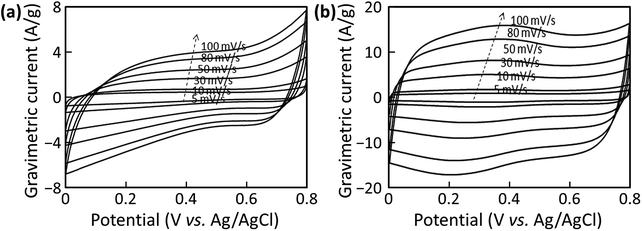 | ||
Fig. 8 CVs measured at different scan rates for the (a) AC1000–FWCNT (9![[thin space (1/6-em)]](https://www.rsc.org/images/entities/char_2009.gif) : :![[thin space (1/6-em)]](https://www.rsc.org/images/entities/char_2009.gif) 1) and (b) AC2000–FWCNT (9 1) and (b) AC2000–FWCNT (9![[thin space (1/6-em)]](https://www.rsc.org/images/entities/char_2009.gif) : :![[thin space (1/6-em)]](https://www.rsc.org/images/entities/char_2009.gif) 1) electrodes. 1) electrodes. | ||
The specific capacitances of the electrodes containing the two types of AC at different scan rates are shown in Fig. 9a. The specific capacitance of the AC2000–FWCNT (9![[thin space (1/6-em)]](https://www.rsc.org/images/entities/char_2009.gif) :
:![[thin space (1/6-em)]](https://www.rsc.org/images/entities/char_2009.gif) 1) electrode was about twice that of the AC1000–FWCNT electrode at a scan rate of 5 mV s−1 (170 F g−1vs. 78 F g−1), and four times higher at a scan rate of 100 mV s−1 (132 F g−1vs. 32 F g−1). This difference, even at low scan rates, resulted from their different SSAs. A higher SSA translates into higher EDL capacitance.46 At low scan rate, the AC pore structure could be fully used,47 yielding the highest EDL capacitance for both electrodes. Faster scan rates caused the performance of both electrodes to decrease, but this decrease was less pronounced for the AC2000–FWCNT electrode than the AC1000–FWCNT one because of its smaller ESR.
1) electrode was about twice that of the AC1000–FWCNT electrode at a scan rate of 5 mV s−1 (170 F g−1vs. 78 F g−1), and four times higher at a scan rate of 100 mV s−1 (132 F g−1vs. 32 F g−1). This difference, even at low scan rates, resulted from their different SSAs. A higher SSA translates into higher EDL capacitance.46 At low scan rate, the AC pore structure could be fully used,47 yielding the highest EDL capacitance for both electrodes. Faster scan rates caused the performance of both electrodes to decrease, but this decrease was less pronounced for the AC2000–FWCNT electrode than the AC1000–FWCNT one because of its smaller ESR.
Fig. 9b and c shows that the magnitude of the ESRs determined from the diameter of the high-frequency semicircle in the Nyquist plots was 1.1 Ω for the AC2000–FWCNT electrode and 2.4 Ω for the AC1000–FWCNT electrode. At low frequencies, the AC2000–FWCNT electrode exhibited a straight vertical line parallel to the imaginary axis, typical of an ideally polarisable electrode. The line in this region of the Nyquist plot of the AC1000–FWCNT electrode inclines to the imaginary axis, and its angle indicates the diffusive resistance of the electrolyte in the electrode.41,48
For EC applications, carbon materials with high SSAs usually have high energy densities because there is more area for charge accumulation and EDL formation. Other factors such as electrical conductivity, pore size distribution, type of electrolyte and surface chemistry also play major roles in the capacitance of a material, and the relationship between specific capacitance and surface area is not linear.49 To enhance the electrical contact between AC and CNTs, the number of contact points between the FWCNTs and AC particles in the parallel circuit should be increased. This can be achieved by dispersing and separating AC particles, and binding them with FWCNTs. The number of contacts between the FWCNTs in a series circuit can also be decreased by increasing the FWCNT length. Longer FWCNTs can reduce the number of contact points in series, and compensate for the poor conductivity of the porous AC particles.
Effect of FWCNT loading on electrode performance
A higher FWCNT loading results in higher conductivity and rate performance, but lower SSA and increased cost. The effect of FWCNT loading on electrode performance was investigated, and the results are shown in Fig. 10a.33 Without FWCNTs but with 5 wt% AB and 5 wt% PTFE, which are respectively conductive and binding additives commonly used in ECs, the specific capacitance of the electrode was reasonable at low scan rate (148 F g−1 at 5 mV s−1), but decreased sharply at high scan rates to 74 F g−1 at 100 mV s−1. The addition of 5 wt% FWCNTs in place of AB and PTFE caused the conductivity to increase considerably, and resulted in specific capacitance of 172 and 119 F g−1 at 5 and 100 mV s−1, respectively. For the electrode with 20 wt% FWCNTs, the decrease in specific capacitance with scan rate was less pronounced (112 F g−1 at 100 mV s−1), although the maximum specific capacitance decreased to 149 F g−1 at 5 mV s−1. A mid-point occurred for the electrode containing 10 wt% FWCNTs, where the performance was the highest across a wide range of scan rates (170 F g−1 at 5 mV s−1 and 132 F g−1 at 100 mV s−1). In addition, 10 wt% FWCNTs is sufficiently low that its cost will not be significant. The performance of electrodes containing AB and PTFE as binders serves as a reference for the performance of a conventional capacitor, and clearly reveals the advantages of using a FWCNT matrix instead.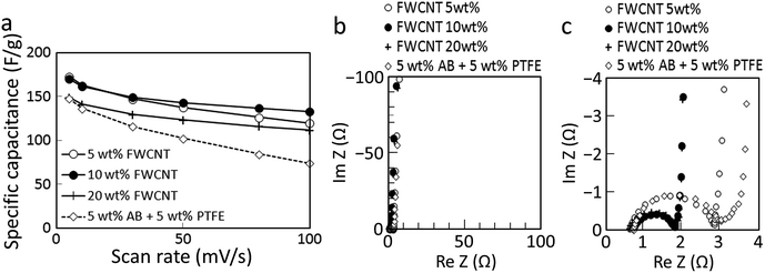 | ||
| Fig. 10 (a) Rate performance determined from CV measurements for AC2000–FWCNT hybrid electrodes with different FWCNT loading.33 The performance of the conventional architecture of 90 wt% AC2000 with 5 wt% AB and 5 wt% PTFE is also shown. Nyquist plots for the same electrodes for the (b) whole range and (c) high-frequency range. | ||
ESR of the conventional architecture (5 wt% AB + 5 wt% PTFE) and 5 wt% FWCNT electrodes were determined from Nyquist plots (Fig. 10b and c), revealing comparable internal resistances of 2.3 and 2.2 Ω, respectively. Electrodes containing 10 and 20 wt% FWCNTs both exhibited smaller internal resistances of 1.1 Ω.
Comparison between the representative electrodes
For real device applications, in addition to specific capacitance, volumetric capacitance and areal capacitance are very important. Table 3 summarizes the structure, property, and capacitance values for the representative AC–AB–PTFE, pure-SWCNT, and AC2000–FWCNT electrodes. These electrodes had mass densities of 0.35–0.50 g cm−3, which is close to the conventional AC-based electrodes (∼0.5 g cm−3).50 Small loading density can yield high specific capacitance values but high loading density is essential for real device (note that a current collector of 15 μm-thick Al foil is as heavy as 4 mg cm−2). All these electrodes have high loading densities of 5.0–8.2 g cm−3. The conventional AC–AB–PTFE electrode showed high specific, volumetric, and areal capacitance values at a low scan rate of 5 mV s−1 but inferior values at a high scan rate of 100 mV s−1 due to the small conductivity of 0.16 S cm−1. The pure-SWCNT electrode showed small capacitance values, which remained almost constant for different scan rates due to the high conductivity of 118 S cm−1. The AC2000–FWCNT electrode showed the best balance; high specific, volumetric, and areal capacitances at both low and high scan rates, due to the high AC content of 90% and fair conductivity of 10.1 S cm−1.| AC–AB–PTFE (conventional) | Pure-SWCNT (SDBS) | AC2000–FWCNT (9![[thin space (1/6-em)]](https://www.rsc.org/images/entities/char_2009.gif) : :![[thin space (1/6-em)]](https://www.rsc.org/images/entities/char_2009.gif) 1) (EtOH) 1) (EtOH) |
|
|---|---|---|---|
| Thickness (μm) | 231 | 100 | 122 |
| Mass density (g cm−3) | 0.35 | 0.50 | 0.44 |
| Loading density (mg cm−2) | 8.2 | 5.0 | 5.3 |
| Conductivity (S cm−1) | 0.16 | 118 | 10.1 |
| Specific capacitance (F g−1) (at 5–100 mV s−1) | 148–74 | 55–52 | 170–132 |
| Volumetric capacitance (F cm−3) (at 5–100 mV s−1) | 52–26 | 28–26 | 74–58 |
| Areal capacitance (F cm−2) (at 5–100 mV s−1) | 1.21–0.60 | 0.28–0.26 | 0.91–0.70 |
Conclusions
CNTs have been widely used to make hybrid electrodes with various capacitive particles for ECs. Because the overall performance of hybrid electrodes mainly depends on their structure, we systematically examined the materials and process conditions for hybrid electrodes using AC as a capacitive material and vacuum filtration processing. SDBS was a good CNT dispersant, and enhanced the conductivity of pure CNT films more than EtOH and NMP. EtOH was a poor CNT dispersant, but was better for retaining the capacitance of AC than H2O–SDBS, because of its easy removal from AC pores. SWCNTs were better suited for pure CNT electrodes than FWCNTs because of their large SSA and conductivity. Meanwhile, FWCNTs were better suited for AC–CNT hybrid electrodes because of their better dispersion in EtOH than SWCNTs. Combining FWCNTs as a conductive matrix with EtOH as a dispersant to prepare AC–CNT hybrid electrodes achieved the highest performance of the examined combinations.The FWCNTs provided a highly conductive network that captured the AC particles in the hybrid electrodes processed in EtOH. Smaller AC particles with larger SSAs were better capacitive materials than larger particles because their interiors could be used at reasonable rates. Addition of 10 wt% FWCNTs to AC yielded a self-supporting hybrid electrode that exhibited the best balance of rate performance and capacitance of those investigated and recorded 170–132 F g−1, 74–58 F cm−3, and 0.91–0.70 F cm−2 at 5–100 mV s−1 for fairly large thickness (122 μm), mass density (0.44 g cm−3), and loading density (5.3 mg cm−2). The addition of a small proportion of CNTs to AC is practical from an economical viewpoint. Careful processing of such hybrid structures will realise further improvements in the performance of hybrid capacitor electrodes.
Acknowledgements
The authors thank Prof. Kuroda, Prof. Shimojima and Mr Yamamoto at Waseda University for their support with BET measurements and Kuraray Co., Ltd. for AC particles. This study was supported by a Grant-in-Aid for Scientific Research (A) (no. 25249111) from Japan Society for the Promotion of Science, Japan, and by the Advanced Low Carbon Technology Research and Development (ALCA) Program from Japan Science and Technology Agency, Japan.Notes and references
- P. Simon and Y. Gogotsi, Nat. Mater., 2008, 7, 845 CrossRef PubMed.
- L. L. Zhang, R. Zhou and X. S. Zhao, J. Mater. Chem., 2010, 20, 5983 RSC.
- A. Lewandowski and M. Galinski, J. Power Sources, 2007, 173, 822 CrossRef CAS.
- J. P. Zheng, P. J. Cygan and T. R. Jow, J. Electrochem. Soc., 1995, 142, 2699 CrossRef CAS.
- C.-C. Hu and T.-W. Tsou, Electrochem. Commun., 2002, 4, 105 CrossRef CAS.
- C.-C. Hu and T.-W. Tsou, Electrochim. Acta, 2002, 47, 3523 CrossRef CAS.
- Y. Honda, T. Haramoto, M. Takeshige, H. Shiozaki, T. Kitamura, K. Yoshikawa and M. Ishikawa, J. Electrochem. Soc., 2008, 155, A930 CrossRef CAS.
- C. Niu, E. K. Sichel, R. Hoch, D. Moy and H. Tennent, Appl. Phys. Lett., 1997, 70, 1480 CrossRef.
- A. Izadi-Najafabadi, S. Yasuda, K. Kobashi, T. Yamada, D. N. Futaba, H. Hatori, M. Yumura, S. Iijima and K. Hata, Adv. Mater., 2010, 22, E235 CrossRef CAS PubMed.
- T. Kudo, Y. Ikeda, T. Watanabe, M. Hibino, M. Miyayama, H. Abe and K. Kajita, Solid State Ionics, 2002, 152–153, 833 CrossRef.
- S. W. Lee, J. Kim, S. Chen, P. T. Hammond and Y. Shao-Horn, ACS Nano, 2010, 4, 3889 CrossRef CAS PubMed.
- R. Ma, B. Wei, C. Xu, J. Liang and D. Wu, Bull. Chem. Soc. Jpn., 2000, 73, 1813 CrossRef CAS.
- X. Qin, S. Durbach and G. T. Wu, Carbon, 2004, 42, 451 CrossRef CAS.
- Y. Wang, H. Liu, X. Sun and I. Zhitomirsky, Scr. Mater., 2009, 61, 1079 CrossRef CAS.
- Y.-T. Kim, K. Tadai and T. Mitani, J. Mater. Chem., 2005, 15, 4914 RSC.
- W. Lu, L. Qu, K. Henry and L. Dai, J. Power Sources, 2009, 189, 1270 CrossRef.
- L. A. Girifalco, M. Hodak and R. S. Lee, Phys. Rev. B: Condens. Matter, 2000, 62, 13104 CrossRef CAS.
- T. Hertel, R. E. Walkup and P. Avouris, Phys. Rev. B: Condens. Matter, 1998, 58, 13870 CrossRef CAS.
- S. Berber, Y.-K. Kwon and D. Tománek, Phys. Rev. Lett., 2000, 84, 4613 CrossRef PubMed.
- J. N. Coleman, U. Khan and Y. K. Gun'ko, Adv. Mater., 2006, 18, 689 CrossRef.
- Q. Zhang, J.-Q. Huang, M.-Q. Zhao, W.-Z. Qian and F. Wei, ChemSusChem, 2011, 4, 864 CrossRef CAS PubMed.
- D. Y. Kim, H. Sugime, K. Hasegawa, T. Osawa and S. Noda, Carbon, 2011, 49, 1972 CrossRef CAS.
- Z. Chen, D. Y. Kim, K. Hasegawa, T. Osawa and S. Noda, Carbon, 2014, 80, 339 CrossRef CAS.
- D. Y. Kim, H. Sugime, K. Hasegawa, T. Osawa and S. Noda, Carbon, 2012, 50, 1538 CrossRef CAS.
- S. W. Lee, B. M. Gallant, Y. Lee, N. Yoshida, D. Y. Kim, Y. Yamada, S. Noda, A. Yamada and Y. Shao-Horn, Energy Environ. Sci., 2012, 5, 5437 CAS.
- C. Emmenegger, P. Mauron, P. Sudan, P. Wenger, V. Hermann, R. Gallay and A. Züttel, J. Power Sources, 2003, 124, 321 CrossRef CAS.
- W. Lu, R. Hartman, L. Qu and L. Dai, J. Phys. Chem. Lett., 2011, 2, 655 CrossRef CAS.
- C. Portet, P. L. Taberna, P. Simon and E. Flahaut, J. Power Sources, 2005, 139, 371 CrossRef CAS.
- Y. Show and K. Imaizumi, Diamond Relat. Mater., 2006, 15, 2086 CrossRef.
- H. Chen, J. Di, Y. Jin, M. Chen, J. Tian and Q. Li, J. Power Sources, 2013, 237, 325 CrossRef CAS.
- J. Smithyman, A. Moench, R. Liang, J. Zheng, B. Wang and C. Zhang, Appl. Phys. A, 2012, 107, 723 CrossRef CAS.
- G. Xu, C. Zheng, Q. Zhang, J. Huang, M. Zhao, J. Nie, X. Wang and F. Wei, Nano Res., 2011, 4, 870 CrossRef CAS.
- R. Quintero, D. Y. Kim, K. Hasegawa, Y. Yamada, A. Yamada and S. Noda, RSC Adv., 2014, 4, 8230 RSC.
- W. G. Pell and B. E. Conway, J. Power Sources, 2001, 96, 57 CrossRef CAS.
- H. Tantang, J. Y. Ong, C. L. Loh, X. Dong, P. Chen, Y. Chen, X. Hu, L. P. Tan and L.-J. Li, Carbon, 2009, 47, 1867 CrossRef CAS.
- Y.-T. Kim, Y. Ito, K. Tadai, T. Mitani, U.-S. Kim, H.-S. Kim and B.-W. Cho, Appl. Phys. Lett., 2005, 87, 234106 CrossRef.
- L. Lai, H. Yang, L. Wang, B. K. Teh, J. Zhong, H. Chou, L. Chen, W. Chen, Z. Shen, R. S. Ruoff and J. Lin, ACS Nano, 2012, 6, 5941 CrossRef CAS PubMed.
- S. K. Park, Q. Mahmood and H. S. Park, Nanoscale, 2013, 5, 12304 RSC.
- E. Raymundo-Piñero, M. Cadek, M. Wachtler and F. Béguin, ChemSusChem, 2011, 4, 943 CrossRef PubMed.
- Y. Wang, Z. Iqbal and S. Mitra, J. Am. Chem. Soc., 2006, 128, 95 CrossRef CAS PubMed.
- J. Shen, A. Liu, Y. Tu, G. Foo, C. Yeo, M. B. Chan-Park, R. Jiang and Y. Chen, Energy Environ. Sci., 2011, 4, 4220 CAS.
- J. Hilding, E. A. Grulke, Z. George Zhang and F. Lockwood, J. Dispersion Sci. Technol., 2003, 24, 1 CrossRef CAS.
- A. Yu, V. Chabot and J. Zhang, Electrochemical Supercapacitors: Energy Storage Delivery Fundamentals Applications, Taylor & Francis, 2013 Search PubMed.
- R. Zhang, B. Zhou, Q.-G. Guo, X.-J. Duan, X.-M. Liu, L.-C. Ling and M.-L. Jing, Materials for Renewable Energy & Environment (ICMREE), 2011 International Conference on (vol. 1), IEEE, 2011, p. 635 Search PubMed.
- K.-W. Kim, M. Kuppuswamy and R. F. Savinell, J. Appl. Electrochem., 2000, 30, 543 CrossRef CAS.
- M. J. Bleda-Martínez, J. A. Maciá-Agulló, D. Lozano-Castelló, E. Morallón, D. Cazorla-Amorós and A. Linares-Solano, Carbon, 2005, 43, 2677–2684 CrossRef.
- R. Kötz and M. Carlen, Electrochim. Acta, 2000, 45, 2483 CrossRef.
- J. H. Jang, S. Yoon, B. H. Ka, Y.-H. Jung and S. M. Oh, J. Electrochem. Soc., 2005, 152, A1418 CrossRef CAS.
- R. Signorelli, D. C. Ku, J. G. Kassakian and J. E. Schindall, Proc. IEEE, 2009, 97, 1837 CrossRef CAS.
- F. Béguin and E. Frackowiak, Carbons for Electrochemical Energy Storage and Conversion Systems, CRC Press, 2010 Search PubMed.
Footnote |
† Electronic supplementary information (ESI) available: Elemental composition (wt%) of pure FWCNT electrodes and AC2000–SWCNT (9![[thin space (1/6-em)]](https://www.rsc.org/images/entities/char_2009.gif) : :![[thin space (1/6-em)]](https://www.rsc.org/images/entities/char_2009.gif) 1) electrodes processed in H2O–SDBS, NMP and EtOH determined by XRF. See DOI: 10.1039/c4ra16560h 1) electrodes processed in H2O–SDBS, NMP and EtOH determined by XRF. See DOI: 10.1039/c4ra16560h |
| This journal is © The Royal Society of Chemistry 2015 |

