Pair-eigenstates and mutual alignment of coupled molecular rotors in a magnetic field
Received
18th January 2016
, Accepted 13th April 2016
First published on 22nd April 2016
Abstract
We examine the rotational states of a pair of polar 2Σ molecules subject to a uniform magnetic field. The electric dipole–dipole interaction between the molecules creates entangled pair-eigenstates of two types. In one type, the Zeeman interaction between the inherently paramagnetic molecules and the magnetic field destroys the entanglement of the pair-eigenstates, whereas in the other type it does not. The pair-eigenstates exhibit numerous intersections, which become avoided for pair-eigenstates comprised of individual states that meet the selection rules ΔJi = 0, ± 1, ΔNi = 2n (n = 0, ±1, ±2,…), and ΔMi = 0, ± 1 imposed by the electric dipole–dipole operator. Here Ji, Ni and Mi are the total, rotational and projection angular momentum quantum numbers of molecules i = 1, 2 in the absence of the electric dipole–dipole interaction. We evaluate the mutual alignment of the pair-eigenstates and find it to be independent of the magnetic field, except for states that undergo avoided crossings, in which case the alignment of the interacting states is interchanged at the magnetic field corresponding to the crossing point. We present an analytic model which provides ready estimates of the pairwise alignment cosine that characterises the mutual alignment of the pair of coupled rotors.
I Introduction
External electric, magnetic and optical fields can be used to manipulate not only the rotational1–32 and translational33–48 motion of individual molecules but also to modify and engineer intermolecular potentials.49–51 This is of relevance to few- and many-body physics where the ability to manipulate intermolecular potentials can be harnessed to, for instance, engineer new phases,52,53 implement Hubbard-type Hamiltonians with controllable parameters,54 simulate spin models,55 or realise the dissipative bond.56,57 In our recent work,50,51 we presented a method for manipulating the interaction potential between a pair of polar 1Σ molecules with far-off-resonant light. That method is based on the triple-combination of the electric dipole–dipole, anisotropic polarisability, and the retarded induced dipole–dipole interactions and offers a wide tunability range of the intermolecular potentials that it generates.
Herein, we examine how the electric dipole–dipole interaction potential between two polar 2Σ molecules – which are inherently paramagnetic – creates entangled pair-eigenstates and how these are affected by the Zeeman interaction between the molecules and a superimposed magnetic field. The electric dipole–dipole intermolecular potential couples Zeeman levels that fulfil selection rules imposed by the electric dipole–dipole operator. This coupling alters the Zeeman levels of the pair-eigenstates in general and modifies the mutual alignment of the two molecular rotors in particular. We are reminded of the coupling of the Zeeman levels of a single polar paramagnetic molecule by a superimposed electric field,8,9 whose interaction with the body-fixed electric dipole of the polar molecule plays the role of the electric dipole–dipole interaction (although under different selection rules). However, the pair-eigenstates exhibit a behaviour quite different from that of single-molecule eigenstates. For instance, we find that the field-free pair-eigenstates are the maximally entangled Bell states.58 The application of a magnetic field is akin to effecting a Bell measurement that results in destroying the pair's entanglement. We made use of these features to propose a new prototype design for a universal quantum computer based on an array of trapped 2Σ molecules.59 Previous proposals relied on the Stark states of trapped polar linear60–62 and symmetric top63 molecules as qubits.
This paper is organised as follows. In Section II, we present the basic theory of the interaction of a pair of polar 2Σ molecules with a magnetic field, starting with a single such molecule in Section II A and laying out the full-fledged theory for the two-molecule system in Section II B. In Section III, we present and discuss our results on the two-molecule system in the absence (Section III A) and presence of a weak (Section III B) and strong (Section III C) electric dipole–dipole coupling as a function of the magnetic field strength. In Section III D we present and discuss our results on the mutual alignment of the two molecules and in Section III E we introduce a model for evaluating the mutual alignment of two coupled molecular rotors. Section IV provides a summary of our results. Appendices 5 and 6 show derivations of the matrix elements of the electric dipole–dipole operator and the pairwise alignment cosine in the cross-product basis set of the two molecules.
II Theory
A The Hamiltonian of a polar 2Σ molecule in a magnetic field
We first consider an individual polar 2Σ molecule in a uniform magnetic (Zeeman) field. Its Hamiltonian (apart from nuclear spin) is given by the sum of the rotational and Zeeman terms.8,32,64–66| | | H = BN2 + γN·S + BηmSZ | (1) |
where B is the rotational constant, N the rotational angular momentum operator, S the electronic spin angular momentum operator, γ the spin-rotation coupling constant and SZ the space-fixed Z component of the molecule's electronic spin. The dimensionless magnetic interaction parameter is given by| |  | (2) |
where μm = gSμB is the electronic magnetic dipole moment of the 2Σ molecule, gS ≅ 2.0023 the electronic gyromagnetic ratio, μB the Bohr magneton and  the magnetic field strength.
Fig. 1 shows the body- and space-fixed frames of reference (x, y, z) and (X, Y, Z), respectively, along with the Euler angles (ϕ, θ, χ) that describe their mutual rotation. The angular momenta N (rotational), J (total) and S (electron spin) are also shown, along the projections M and Ω of the total angular momentum J on the space fixed Z-axis and molecule fixed z-axis, respectively. Note that N = J − S.
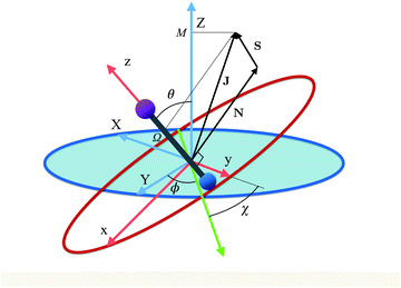 |
| | Fig. 1 Euler angles (ϕ, θ, χ) describing the rotation of the molecular coordinates (x, y, z) fixed to a diatomic molecule (depicted as a bar-bell) with respect to the space-fixed coordinates (X, Y, Z). The green axis is the line of nodes, perpendicular to both z and Z. Also shown are the rotational, N, electron spin, S, and total, J, angular momenta as well as the projections M and Ω of J on the z and Z axes, respectively. | |
While for a 2Σ state the electronic spin angular momentum S = ½, the orbital electronic angular momentum is identically zero and so is the spin–orbit coupling. A field-free 2Σ state thus exhibits a Hund's case (b) coupling between the rotational and electronic angular momenta,64 with the projections of the total and spin electronic angular momenta on the molecular axis (an axis of cylindrical symmetry) Ω = Σ = ½, cf.Fig. 1.
The Hund's case (b) basis functions are equally weighted linear combinations of Hund's case (a) basis functions, each a product of a symmetric top wave function,
| |  | (3) |
and a spin function,
66| |  | (4) |
with
J =
N ±
S the total (rotation and electron spin) angular momentum quantum number,
M and
Ω the projections of the total angular momentum on, respectively, the space-fixed
Z axis and the body-fixed
z axis,
![[Fraktur D]](https://www.rsc.org/images/entities/char_e181.gif) JM,Ω
JM,Ω(
ϕ,
θ,
χ) the Wigner matrix, with
ϕ,
θ,
χ the Euler angles, and
α,
β the spin functions. Thus for a field-free
2Σ state, there are two types of Hund's case (b) basis functions
| |  | (5) |
pertaining to
J =
N ± ½, with parity (−1)
N. The corresponding eigenenergies are
| |  | (6) |
| |  | (7) |
We note that both
J and
N but not
Ω are good quantum numbers for a field-free
2Σ molecule.
The SZ operator couples Hund's case (b) basis functions with same M but with Ns that are either the same or differ by ±2 and hence have the same parity. The selection rule on N moreover ensures that the Hamiltonian matrix in the Hund's case (b) basis for the Zeeman interaction of a 2Σ molecule factors into blocks that are no greater than 2 × 2, rendering the corresponding Zeeman energy at most quadratic in  .
.
The Zeeman states |Ñ, ![[J with combining tilde]](https://www.rsc.org/images/entities/i_char_004a_0303.gif) , M; ηm〉 of a 2Σ molecule adiabatically correlate with the field-free rotor states |N, J, M〉 such that |Ñ,
, M; ηm〉 of a 2Σ molecule adiabatically correlate with the field-free rotor states |N, J, M〉 such that |Ñ, ![[J with combining tilde]](https://www.rsc.org/images/entities/i_char_004a_0303.gif) , M; ηm → 0〉 → |N, J, M〉, where Ñ and
, M; ηm → 0〉 → |N, J, M〉, where Ñ and ![[J with combining tilde]](https://www.rsc.org/images/entities/i_char_004a_0303.gif) are adiabatic labels rather than quantum numbers. The projection quantum number M and the parity (−1)Ñ remain good quantum number even in the presence of the Zeeman field. The effects of the magnetic field on 2Σ molecules have been discussed in greater detail, e.g., in ref. 8 and 32.
are adiabatic labels rather than quantum numbers. The projection quantum number M and the parity (−1)Ñ remain good quantum number even in the presence of the Zeeman field. The effects of the magnetic field on 2Σ molecules have been discussed in greater detail, e.g., in ref. 8 and 32.
B The Hamiltonian of a pair of polar 2Σ molecules in a magnetic field
We now consider a pair of polar 2Σ molecules in the presence of a uniform magnetic field. The Hamiltonian of such a composite, two-molecule system is the sum of the single-molecule Hamiltonians, Hi, and the electric and magnetic dipole–dipole coupling terms. Upon neglecting the much weaker magnetic dipole–dipole interaction, the Hamiltonian takes the form| |  | (8) |
where i = 1, 2 and Vd–d is the electric dipole–dipole interaction operator.
The two molecule system is shown in Fig. 2, along with the space- and body-fixed reference frames (X, Y, Z) and (x, y, z). While the Z axis is defined by the direction of the magnetic field vector, the z-axis coincides with the intermolecular axis. The Euler angles (ϕ, θ, χ) parametrize the rotation matrix which transforms between the laboratory (space-fixed) and intermolecular (body-fixed) frames.67 The rotations between the body-fixed frames of molecules 1 and 2 and the laboratory frame are described by Euler angles (ϕ1, θ1, χ1) and (ϕ2, θ2, χ2).
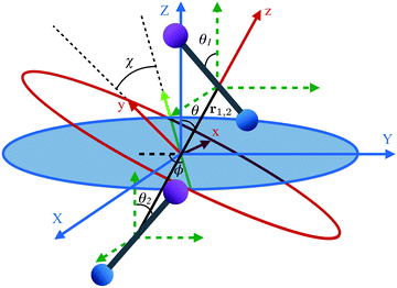 |
| | Fig. 2 Definition of Euler angles (ϕ, θ, χ) describing the rotation of the intermolecular co-ordinate (x, y, z) with respect to the space-fixed coordinates (X, Y, Z) for two diatomic molecules depicted as bar-bells. The intermolecular frame of reference has its z-axis aligned along the internuclear axis, r1,2. The green dashed coordinates are the space fixed coordinates (X, Y, Z) translated to each molecule. The Euler angles for each molecule introduced in Fig. 1 are from here on represented using subscripts 1 and 2 for each molecule. | |
The electric dipole–dipole interaction potential is given by
| |  | (9) |
with
μ1 and
μ2 the electric dipole moments of the two molecules and
r1,2 the relative position vector of the centres of mass of the two molecules whose direction is given by the unit vector

, and
ε0 is the permittivity of the vacuum. As usual,
r1,2 ≡ |
r1,2| and
μi ≡ |
μi| (with
i = 1, 2). Moreover, in our case,
μ1 =
μ2 ≡
μ.
Eqn (9) can be recast in terms of the Wigner matrices ![[scr D, script letter D]](https://www.rsc.org/images/entities/char_e523.gif) lm0(ϕ, θ, χ):
lm0(ϕ, θ, χ):
| |  | (10) |
where
C(
J1,
J2,
J3;
M1,
M2,
M3) are the Clebsch–Gordan coeffcients,
J1 and
J2 the angular momentum quantum numbers of molecules 1 and 2,
M1 and
M2 the projections of the angular momenta of molecules 1 and 2 on the space fixed axis
Z,
J3 and
M3 their respective sums, (
θ1,
ϕ1) and (
θ2,
ϕ2) the rotational coordinates of molecules 1 and 2, (
θ,
ϕ) the spherical coordinates of their relative position vector
r1,2, and
| |  | (11) |
is a parameter that characterises the strength of the electric dipole–dipole interaction. The dimensionless parameter

measures the strength of the electric dipole–dipole interaction in terms of the rotational constant.
The matrix elements of the Hamiltonian were calculated analytically in the cross product Hund's case (a) basis set,
| | | |J1, Ω1, M1, S1, Σ1; J2, Ω2, M2, S2, Σ2〉 = |J1Ω1M1〉 |S1Σ1〉 ⊗ |J2Ω2M2〉 |S2Σ2〉 | (12) |
of the two molecules and the eigen properties of the composite two-molecule system obtained by a numerical diagonalization of a truncated Hamiltonian matrix, whose structure is shown in
Fig. 3.
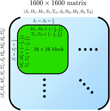 |
| | Fig. 3 Matrix representation of Hamiltonian of eqn (8) in the cross product basis set |J1, Ω1, M1, S1, Σ1; J2, Ω2, M2, S2, Σ2〉 of two Hund's case (b) molecules, truncated such that Ji with i = 1, 2 ranges from ½ to  for molecules 1 and 2 (shown in blue). Hence Mi ranges from −Ji to Ji while for molecules 1 and 2 (shown in blue). Hence Mi ranges from −Ji to Ji while  . Same applies to primed quantities. Note that for instance J1 = J2 = ½ = J1′ = J2′ give rise to a 16 × 16 sub-matrix (shown in green). The size of the blocks increases with J1 and J2, since Mi = −Ji, −Ji + 1,…Ji (i = 1, 2). Note that due to the coupling with the external magnetic field and the intermolecular interaction, the Hamiltonian matrix is not block diagonal. The dots stand for blocks of the matrix. See text. . Same applies to primed quantities. Note that for instance J1 = J2 = ½ = J1′ = J2′ give rise to a 16 × 16 sub-matrix (shown in green). The size of the blocks increases with J1 and J2, since Mi = −Ji, −Ji + 1,…Ji (i = 1, 2). Note that due to the coupling with the external magnetic field and the intermolecular interaction, the Hamiltonian matrix is not block diagonal. The dots stand for blocks of the matrix. See text. | |
Note that the projection quantum numbers Ωi and Σi (with i = 1, 2) of the electronic angular momenta on the body-fixed axis of each 2Σ molecule coincide, i.e., Ωi = Σi. The number of pairs of states determines the size of the basis set and is given by  . For Jmin = ½ and
  , this means that the truncated Hamiltonian matrix is of a 1600 rank. We note that while there is no apparent difference in the sparsity of the Hamiltonian matrices in Hunds case (a) and (b) basis sets, the computation of the Hund's case (a) matrix elements is about four-times faster than that of the Hunds case (b) matrix elements.
The matrix elements in the cross product of Hund's case (a) basis of the two molecules have been obtained in closed form, see Appendix A:
| | 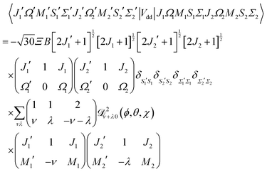 | (13) |
Eqn (13) implies that the electric dipole–dipole interaction couples states with Δ
M1 = 0, ±1, Δ
J1 = 0, ±1, Δ
M2 = 0, ±1 and Δ
J2 = 0, ±1 of molecules 1 and 2. Thus, even in the absence of external fields,
M is not a good quantum number in the presence of the electric dipole–dipole interaction. In Section III B we will introduce a labelling of states that circumvents this difficulty.
III Results and discussion
The diagonalization of the 1600 × 1600 Hamiltonian matrix was carried out using the Armadillo C++ linear algebra library.68 The states were adiabatically tracked as a function of the magnetic field interaction parameter ηm by monitoring the inner product between the eigenvector of a given state at the initial value of ηm and all possible eigenvectors for the new value of ηm. The calculations presented here were carried out for a generic 2Σ molecule with the value of γ taken to be 0.193, which corresponds to the NaO (A2Σ) molecule. Its molecular parameters along with those of additional choice molecules with a 2Σ ground state are summarised in Table 1.
Table 1 Rotational constants, B, spin-rotation constants, γ, electric dipole moments, μ, and values of the dimensionless interaction parameter ηm at a magnetic field of 1 Tesla for NaO(A2Σ) and for choice molecules with a 2Σ ground state. Also shown are the values of the dimensionless electric dipole–dipole interaction parameter Ξ, see eqn (11). Compilation based on ref. 8, 32 and 69 and our own calculations
| |
B [cm−1] |
γ [cm−1] |
μ [D] |
η
m@1 T |
Ξ (r1,2 = 500 nm) |
|
Calculated using Gaussian 09.
B3LYP type calculation using TZP-DKH basis.70,71
|
| NaO |
0.462 |
0.193 |
7.88a,b |
2.02 |
5.42 × 10⁻⁶ |
| CaH |
4.28 |
0.045 |
2.94 |
0.22 |
8.14 × 10⁻⁸ |
| CaF |
0.34 |
0.0013 |
3.34 |
2.75 |
1.32 × 10⁻⁶ |
| MgH |
5.83 |
0.020 |
1.27 |
0.16 |
1.12 × 10⁻⁸ |
| RbO |
0.24 |
0.019 |
8.5 |
3.9 |
1.21 × 10⁻⁵ |
| BeH |
10.32 |
0.005 |
0.1069 |
0.09 |
4.46 × 10⁻¹¹ |
| CN |
1.99 |
0.0073 |
1.45 |
0.47 |
4.2 × 10⁻⁸ |
| CaCl |
0.15 |
0.0014 |
4.47 |
6.23 |
5.37 × 10⁻⁶ |
A Pair-eigenstates in the absence of the electric dipole–dipole coupling, Ξ = 0
In the absence of the electric dipole–dipole interaction, i.e., for Ξ = 0, the pair-eigenstates of the two-molecule system can be decomposed into products of eigenstates of the individual molecules,| | |![[J with combining tilde]](https://www.rsc.org/images/entities/i_char_004a_0303.gif) 1, Ñ1, 1, Ñ1, ![[M with combining tilde]](https://www.rsc.org/images/entities/i_char_004d_0303.gif) 1; 1; ![[J with combining tilde]](https://www.rsc.org/images/entities/i_char_004a_0303.gif) 2, Ñ2, 2, Ñ2, ![[M with combining tilde]](https://www.rsc.org/images/entities/i_char_004d_0303.gif) 2; ηm〉 = | 2; ηm〉 = |![[J with combining tilde]](https://www.rsc.org/images/entities/i_char_004a_0303.gif) 1, Ñ1, 1, Ñ1, ![[M with combining tilde]](https://www.rsc.org/images/entities/i_char_004d_0303.gif) 1; ηm〉 | 1; ηm〉 |![[J with combining tilde]](https://www.rsc.org/images/entities/i_char_004a_0303.gif) 2, Ñ2, 2, Ñ2, ![[M with combining tilde]](https://www.rsc.org/images/entities/i_char_004d_0303.gif) 2; ηm〉 2; ηm〉 | (14) |
This implies that the two Hamiltonians H1 and H2, cf.eqn (1) and (8), can be diagonalised separately in order to obtain the eigenfunctions |![[J with combining tilde]](https://www.rsc.org/images/entities/i_char_004a_0303.gif) 1, Ñ1,
1, Ñ1, ![[M with combining tilde]](https://www.rsc.org/images/entities/i_char_004d_0303.gif) 1; ηm〉 and |
1; ηm〉 and |![[J with combining tilde]](https://www.rsc.org/images/entities/i_char_004a_0303.gif) 2, Ñ2,
2, Ñ2, ![[M with combining tilde]](https://www.rsc.org/images/entities/i_char_004d_0303.gif) 2; ηm〉 and the corresponding eigenenergies E1 and E2. The eigenenergy of the two-molecule system is then calculated to be
2; ηm〉 and the corresponding eigenenergies E1 and E2. The eigenenergy of the two-molecule system is then calculated to be
Fig. 4 shows the eigenenergies (in units of the rotational constant B) of the two-molecule system for Ξ = 0. Each set of eigenstates with the same ![[J with combining tilde]](https://www.rsc.org/images/entities/i_char_004a_0303.gif) 1, Ñ1,
1, Ñ1, ![[J with combining tilde]](https://www.rsc.org/images/entities/i_char_004a_0303.gif) 2 and Ñ2 is plotted in the same colour. The projection quantum numbers M1 and M2 of the individual molecules are good quantum numbers in the absence of the electric dipole–dipole interaction.
2 and Ñ2 is plotted in the same colour. The projection quantum numbers M1 and M2 of the individual molecules are good quantum numbers in the absence of the electric dipole–dipole interaction.
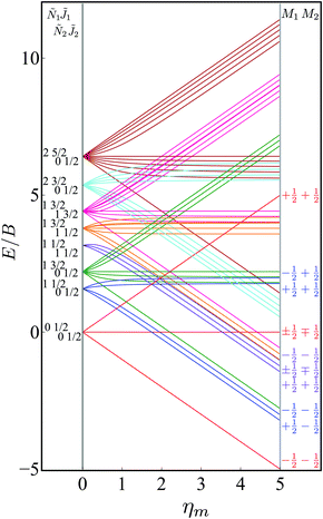 |
| | Fig. 4 Dependence of the eigenenergies E of the system of two polar paramagnetic 2Σ molecules on the magnetic field strength parameter ηm in the absence of the electric dipole–dipole interaction (Ξ = 0). The eigenenergies are measured in terms of the rotational constant B. | |
B Pair-eigenstates in the presence of a small dipole–dipole coupling, Ξ ≪ 1
The pair-eigenstates formed as a result of the electric dipole–dipole interaction can no longer be factored into products of individual molecular eigenstates, as was the case above in eqn (14), and, moreover, even M1 and M2 cease to be good quantum numbers. Fig. 5–7 show correlation diagrams between the individual molecular eigenstates in the absence of the magnetic field (Ξ = 0, ηm = 0) and the pair-eigenstates created by the electric dipole–dipole interaction (Ξ ≠ 0) without (ηm = 0) and with (ηm ≠ 0) the magnetic field for the three lowest sets of pair-eigenstates.
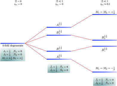 |
| | Fig. 5 Correlation diagram involving the ![[J with combining tilde]](https://www.rsc.org/images/entities/i_char_004a_0303.gif) 1 = ½, Ñ1 = 0, 1 = ½, Ñ1 = 0, ![[J with combining tilde]](https://www.rsc.org/images/entities/i_char_004a_0303.gif) 2 = ½, Ñ2 = 0, pair-eigenstates. The eigenstates, labelled in accordance with Table 2, are degenerate in the absence of the electric dipole–dipole interaction (their multiplicity is indicated by the number of bars) but their degeneracy is lifted when Ξ ≠ 0. The A½ ½+ and A½ ½− states adiabatically transform into M1 = M2 = −½ and M1 = M2 = ½ states, respectively, when the magnetic field is applied. Note that the B states maintain their entanglement throughout. 2 = ½, Ñ2 = 0, pair-eigenstates. The eigenstates, labelled in accordance with Table 2, are degenerate in the absence of the electric dipole–dipole interaction (their multiplicity is indicated by the number of bars) but their degeneracy is lifted when Ξ ≠ 0. The A½ ½+ and A½ ½− states adiabatically transform into M1 = M2 = −½ and M1 = M2 = ½ states, respectively, when the magnetic field is applied. Note that the B states maintain their entanglement throughout. | |
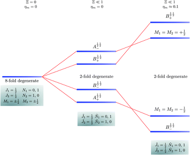 |
| | Fig. 6 Correlation diagram involving the ![[J with combining tilde]](https://www.rsc.org/images/entities/i_char_004a_0303.gif) 1 = ½, Ñ1 = 0, 1, 1 = ½, Ñ1 = 0, 1, ![[J with combining tilde]](https://www.rsc.org/images/entities/i_char_004a_0303.gif) 2 = ½, Ñ2 = 1, 0 pair-eigenstates. The eigenstates, labelled in accordance with Table 2, are eight fold degenerate in the absence of electric dipole–dipole interaction but only doubly degenerate when Ξ ≠ 0 (their multiplicity is indicated by the number of bars). This double degeneracy arises because the indistinguishability of two molecules. A½ ½+ and A½ ½− states adiabatically transform into M1 = M2 = −½ and M1 = M2 = ½ states, respectively, when the magnetic field is applied. Note that the B states maintain their entanglement throughout. 2 = ½, Ñ2 = 1, 0 pair-eigenstates. The eigenstates, labelled in accordance with Table 2, are eight fold degenerate in the absence of electric dipole–dipole interaction but only doubly degenerate when Ξ ≠ 0 (their multiplicity is indicated by the number of bars). This double degeneracy arises because the indistinguishability of two molecules. A½ ½+ and A½ ½− states adiabatically transform into M1 = M2 = −½ and M1 = M2 = ½ states, respectively, when the magnetic field is applied. Note that the B states maintain their entanglement throughout. | |
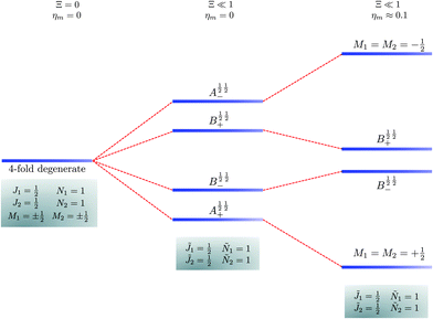 |
| | Fig. 7 Correlation diagram involving the ![[J with combining tilde]](https://www.rsc.org/images/entities/i_char_004a_0303.gif) 1 = ½, Ñ1 = 1, 1 = ½, Ñ1 = 1, ![[J with combining tilde]](https://www.rsc.org/images/entities/i_char_004a_0303.gif) 2 = ½, Ñ2 = 1 pair-eigenstates. The eigenstates, labelled in accordance with Table 2, are degenerate in the absence of the electric dipole–dipole interaction (their multiplicity is indicated by the number of bars) but their degeneracy is lifted when Ξ ≠ 0. A½ ½+ and A½ ½− states adiabatically transform into M1 = M2 = ½ and M1 = M2 = −½ eigenstates, respectively, when the magnetic field is applied. Note that the B states maintain their entanglement throughout. 2 = ½, Ñ2 = 1 pair-eigenstates. The eigenstates, labelled in accordance with Table 2, are degenerate in the absence of the electric dipole–dipole interaction (their multiplicity is indicated by the number of bars) but their degeneracy is lifted when Ξ ≠ 0. A½ ½+ and A½ ½− states adiabatically transform into M1 = M2 = ½ and M1 = M2 = −½ eigenstates, respectively, when the magnetic field is applied. Note that the B states maintain their entanglement throughout. | |
In the absence of the magnetic field and the electric dipole–dipole interaction, the pair-eigenstates are degenerate in M1 and M2 for any given set of J1, N1, J2 and N2. Since M1 = −J1, −J1 + 1,…J1 − 1, J1 and M2 = −J2, −J2 + 1,…J2 − 1, J2, each such set is comprised of (2J1 + 1)(2J2 + 1) degenerate states. The electric dipole–dipole interaction lifts the M-degeneracy as the pair-eigenstates are formed. In the absence of the magnetic field, the pair-eigenstates are equally-weighted linear combinations of the degenerate states of individual molecule with given ±M1 and ±M2. As indicated in the correlation diagrams of Fig. 5–7, these linear combination states are formed irrespective of how small the value of Ξ is. Every ±|M1| and ±|M2| set of degenerate states leads to the formation of four new pair-eigenstates.
Table 2 shows the four possible states formed along with their respective labels. We label the states A if the total angular momenta of the two molecules are parallel, i.e., the state is a linear combination of (+|M1|, +M2) and (−|M1|, −|M2|). The states are labelled B if the total angular momenta of the two molecules are antiparallel. Note that the values of |M1| and |M2| are shown as superscripts whereas the subscripts + and − refer to whether the linear combination is symmetric or antisymmetric.
Table 2 Pair-eigenstates – and their labels – comprised of two states of 2Σ molecules in the presence of the electric dipole–dipole interaction. Note that these labels remain in place irrespective of whether the magnetic field is present
| Label |
State |

|
Ψ(+|M1|, +|M2|) + Ψ(−|M1|, −|M2|) |

|
Ψ(+|M1|, +|M2|) − Ψ(−|M1|, −|M2|) |

|
Ψ(+|M1|, −|M2|) + Ψ(−|M1|, +|M2|) |

|
Ψ(+|M1|, −|M2|) − Ψ(−|M1|, +|M2|) |
As shown in Fig. 5–7, in a magnetic field that lifts the ±M degeneracy, the A states decouple into +|M1|, +|M2| and −|M1|, −|M2| states whereas the B states do not (for as long as M1 = M2). This is because in the B states the two molecules have opposite projections of the angular momentum and the combinations ψ(+|M|, −|M|) and ψ(−|M|, +|M|) are indistinguishable. This preserves the entanglement (the Bell-state character) of the pair-eigenstates even in the presence of a uniform magnetic field. However, the B states decouple in a non-uniform magnetic field.59 This is shown quantitatively in Fig. 8 where the concurrence – a measure of entanglement72 – has been plotted for the A and B states as a function of the superimposed magnetic field.
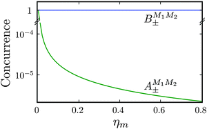 |
| | Fig. 8 Concurrence of type A and B pair-eigenstates, cf.Table 2, as a function of magnetic field. Note that  states become disentangled when the magnetic field is turned on, while the states become disentangled when the magnetic field is turned on, while the  states do not. The concurrence was calculated by the method described in ref. 59. states do not. The concurrence was calculated by the method described in ref. 59. | |
C Pair-eigenstates in the presence of large dipole–dipole coupling, Ξ < 1
In order to make the effect of the electric dipole–dipole interaction on the structure of the pair-eigenenergy levels more apparent, we increased the value of the coupling interaction parameter Ξ to an unrealistically high value of 0.1, see Fig. 9. Each set of pair-eigenstates with the same ![[J with combining tilde]](https://www.rsc.org/images/entities/i_char_004a_0303.gif) 1, Ñ1,
1, Ñ1, ![[J with combining tilde]](https://www.rsc.org/images/entities/i_char_004a_0303.gif) 2 and Ñ2 are shown in the same colour. Since M1 and M2 are mixed, see Section III B, the eigenstates are labeled according to the system defined in Table 2.
2 and Ñ2 are shown in the same colour. Since M1 and M2 are mixed, see Section III B, the eigenstates are labeled according to the system defined in Table 2.
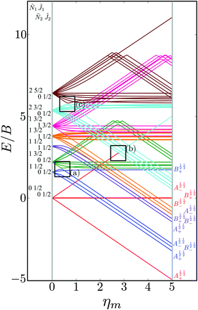 |
| | Fig. 9 Dependence of the eigenenergies E of the system of two polar paramagnetic 2Σ molecules on the magnetic field strength parameter ηm in the presence of the electric dipole–dipole interaction (Ξ = 10−1). The eigenenergies are measured in terms of the rotational constant B. The avoided crossings formed due to electric dipole–dipole interaction are highlighted by the black boxes. cf.Fig. 4. | |
We see that avoided crossings (highlighted by the black boxes) are formed for pair-eigenstates comprised of individual states that meet the selection rules ΔJi = 0, ± 1, ΔNi = 2n (n = 0, ± 1, ± 2,…) and ΔMi = 0, ± 1. These selection rules follow from the properties of the electric dipole–dipole operator, cf.eqn (13).
Fig. 10 shows the first avoided crossing, highlighted by box (a) in Fig. 9, for Ξ = 10−3 (upper panel) and Ξ = 10−5 (lower panel), illustrating the effect of increasing the value of Ξ. The smaller the value of Ξ, the greater the zoom required in order to visualise the avoided crossing.
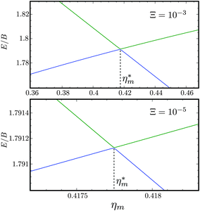 |
| | Fig. 10 Zoomed-in plot of the first avoided crossing highlighted by box (a) in Fig. 9 for Ξ = 10−3 (upper panel) and for Ξ = 10−5 (lower panel). The position of the avoided crossing is marked by the value of the magnetic interaction parameter ηm*. Blue curve: ![[J with combining tilde]](https://www.rsc.org/images/entities/i_char_004a_0303.gif) 1 = ½, Ñ1 = 1, 1 = ½, Ñ1 = 1, ![[J with combining tilde]](https://www.rsc.org/images/entities/i_char_004a_0303.gif) 2 = ½, Ñ2 = 0, B½ ½+; green curve: 2 = ½, Ñ2 = 0, B½ ½+; green curve:  . . | |
D Mutual alignment of the coupled rotors
The orientation and alignment of the two-molecule system is characterised, respectively, by the expectation values of the pairwise alignment cosine cos![[thin space (1/6-em)]](https://www.rsc.org/images/entities/char_2009.gif) θ1
θ1![[thin space (1/6-em)]](https://www.rsc.org/images/entities/char_2009.gif) cos
cos![[thin space (1/6-em)]](https://www.rsc.org/images/entities/char_2009.gif) θ2 and pairwise orientation cosine cos2
θ2 and pairwise orientation cosine cos2![[thin space (1/6-em)]](https://www.rsc.org/images/entities/char_2009.gif) θ1
θ1![[thin space (1/6-em)]](https://www.rsc.org/images/entities/char_2009.gif) cos2
cos2![[thin space (1/6-em)]](https://www.rsc.org/images/entities/char_2009.gif) θ2 operators, see also.50,51 The requisite matrix elements for calculating the pairwise cosines are listed in Appendix B.
θ2 operators, see also.50,51 The requisite matrix elements for calculating the pairwise cosines are listed in Appendix B.
Fig. 11 shows the expectation values of the pairwise orientation and alignment cosines of the ![[J with combining tilde]](https://www.rsc.org/images/entities/i_char_004a_0303.gif) 1 = ½, Ñ1 = 1,
1 = ½, Ñ1 = 1, ![[J with combining tilde]](https://www.rsc.org/images/entities/i_char_004a_0303.gif) 2 = ½, Ñ2 = 0, B½ ½+ state (blue curve in Fig. 9) with the
2 = ½, Ñ2 = 0, B½ ½+ state (blue curve in Fig. 9) with the  state (green curve in Fig. 9) at the avoided crossing for Ξ = 10−5 (lower panel) and Ξ = 10−3 (upper panel) at ηm ≈ 0.41775. Note that these states are not oriented but there is a sudden change in alignment of the two molecules at the avoided crossing.
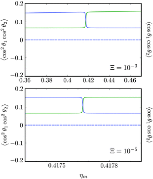 |
| | Fig. 11 Pairwise alignment and orientation cosines of two polar 2Σ molecules near the avoided crossing shown by a box (a) in Fig. 9 as a function of the magnetic field strength parameter ηm for electric dipole–dipole interaction Ξ = 10−3 (upper panel) and Ξ = 10−5 (lower panel). Blue curve: ![[J with combining tilde]](https://www.rsc.org/images/entities/i_char_004a_0303.gif) 1 = ½, Ñ1 = 1, 1 = ½, Ñ1 = 1, ![[J with combining tilde]](https://www.rsc.org/images/entities/i_char_004a_0303.gif) 2 = ½, Ñ2 = 0, B½ ½+; green curve: 2 = ½, Ñ2 = 0, B½ ½+; green curve:  . . | |
As noted in our earlier work,8,9 a small electric field can orient polar paramagnetic molecules in the presence of a magnetic field by virtue of the electric dipole coupling of the Zeeman levels. A similar effect is expected to arise for two polar paramagnetic molecules in a magnetic field due to coupling of their Zeeman levels by the electric dipole–dipole interaction, resulting in their mutual orientation. However, as shown in Fig. 11 (dashed line), the mutual orientation comes to naught. As detailed in Section III B, this is because the pair-eigenstates are equally weighted linear combination of states with opposing angular momentum projections on the space fixed Z axis. In other words, the linear combinations entail indistinguishable pair-eigenstates of types |↑↓〉 and |↓↑〉.
However, the molecules are mutually aligned by the electric dipole–dipole coupling, see Fig. 11.
Fig. 12 shows the corresponding individual orientation and alignment cosines of ![[J with combining tilde]](https://www.rsc.org/images/entities/i_char_004a_0303.gif) 1 = ½, Ñ1 = 1,
1 = ½, Ñ1 = 1, ![[J with combining tilde]](https://www.rsc.org/images/entities/i_char_004a_0303.gif) 2 = ½, Ñ2 = 0, B½ ½+ state (blue curve in Fig. 9) with the
2 = ½, Ñ2 = 0, B½ ½+ state (blue curve in Fig. 9) with the  state (green curve in Fig. 9). The colour coding is the same as in Fig. 9 and 11. We see that the coupling near the avoided crossing changes the alignment of one of the two molecules, which leads to a change in the mutual alignment shown in Fig. 11. For the state
 ![[J with combining tilde]](https://www.rsc.org/images/entities/i_char_004a_0303.gif) 1 = ½, Ñ1 = 1,
1 = ½, Ñ1 = 1, ![[J with combining tilde]](https://www.rsc.org/images/entities/i_char_004a_0303.gif) 2 = ½, Ñ2 = 0, B½ ½+ (blue curve), the alignment of molecule 1 remains constant but the alignment of molecule 2 decreases at the avoided crossing while for the state
2 = ½, Ñ2 = 0, B½ ½+ (blue curve), the alignment of molecule 1 remains constant but the alignment of molecule 2 decreases at the avoided crossing while for the state  the alignment of molecule 1 increases but the alignment of molecule 2 remains constant at the avoided crossing. The relationship between the individual alignment cosines of molecules 1 and 2 and the mutual alignment cosine (for given crossing states) illustrated in Fig. 11 and 12 is rendered by the two-state model below.
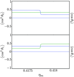 |
| | Fig. 12 Individual alignment and orientation cosines of polar 2Σ molecules 1 and 2 near the avoided crossing shown by a box (a) in Fig. 9 as a function of the magnetic field strength parameter ηm for electric dipole–dipole interaction Ξ = 10−5. Blue curve: ![[J with combining tilde]](https://www.rsc.org/images/entities/i_char_004a_0303.gif) 1 = ½, Ñ1 = 1, 1 = ½, Ñ1 = 1, ![[J with combining tilde]](https://www.rsc.org/images/entities/i_char_004a_0303.gif) 2 = ½, Ñ2 = 0, B½ ½+; green curve: 2 = ½, Ñ2 = 0, B½ ½+; green curve:  . . | |
E Analytic model of pairwise alignment
For Ξ ≪ ηm, the eigenproperties of two interacting eigenstates which cross in the purely magnetic case but form an avoided crossing in the presence of the electric dipole–dipole interaction can be calculated using a two-state model. This model makes use of the two Zeeman eigenfunctions in the absence of electric dipole–dipole coupling as the (unperturbed) basis functions. Thus| |  | (16) |
where H1 and H2 are given by eqn (1) and ψ(0)a ≡ ψa(Ξ = 0) and ψ(0)b ≡ ψb(Ξ = 0), and the subscripts a and b pertain to the two states considered. In the absence of electric dipole–dipole interaction, these eigenfunctions are just a direct product of the eigenfunctions of individual molecules i = 1, 2,| |  | (17) |
where ϕi are the eigenfunctions of Hamiltonian (1) of molecules i = 1, 2. The eigenenergies of the pair-eigenstates a and b in the presence of the electric dipole–dipole coupling are then given by| |  | (18) |
and the corresponding eigenvectors are given by| |  | (19) |
with α the mixing angle| |  | (20) |
where ΔE(0) ≡ E(0)b − E(0)a, Hab is the electric dipole–dipole coupling matrix element between the two unperturbed states,| | | Hab = 〈ψ(0)a|Vdd|ψ(0)b〉 | (21) |
and 0° ≤ α ≤ 90°. Eqn (18) shows that the change in energy due to the electric dipole–dipole interaction is proportional to  . Since Ξ is inversely proportional to the cube of the distance between the molecules, cf.eqn (11), we see that at large intermolecular separations the eigenenergies of the two molecule system due to electric dipole–dipole interaction vary as r1,2−1.
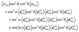
Within the two-state model, the pairwise alignment cosine is given by
| |  | (22) |
Eqn (22) implies that for
ηm <
ηm* (with
ηm* the magnetic field strength parameter corresponding to position of the avoided crossing), where
α = 0°, the pairwise alignment is a product of the alignment of states a of molecules 1 and 2 and beyond the interaction region, where
α = 90°, the pairwise alignment is a product of the alignment of states b of molecules 1 and 2. The pairwise alignment in the interaction (avoided crossing) region is a combination of the alignment of states a and b plus an additional term which comes about due to the interaction. The interaction term reaches its maximum value at
α = 45°.
We note that the maximum value of the pairwise alignment cosine is independent of the strength of the electric dipole–dipole coupling as long as Ξ is nonzero. The pairwise alignment calculated from this model is quite accurate, within ±5% of the exact result for Ξ < 10−3. Hence the model is quite useful, since typically Ξ ≈ 10−5 for polar paramagnetic molecules at a distance of 500 nm apart (for instance when trapped in an optical lattice).
IV Conclusion
Our study of a composite system comprised of two polar 2Σ molecules subject to a uniform magnetic field revealed that the electric dipole–dipole interaction that dominates the intermolecular potential between the two molecules mixes the molecules' M states and in the process creates the maximally entangled Bell states. These are of two types, A and B. While the entanglement of type A states is destroyed by applying a magnetic field (which is tantamount to performing a Bell measurement on the system), the type B states maintain their entanglement even in the presence of a uniform magnetic field. Only a non-uniform magnetic field would destroy their entanglement as well. These features may find application in developing platforms for quantum computing with arrays of trapped molecules.59
Furthermore, we found that the intersecting Zeeman levels of the pair-eigenstates undergo avoided crossings if they obey a set of selection rules imposed by the electric dipole–dipole operator: ΔJi = 0, ±1, ΔNi = 2n (n = 0, ±1, ±2,…), and ΔMi = 0, ±1, with Ji, Ni and Mi the total, rotational and projection angular momentum quantum numbers of molecules i = 1, 2 in the absence of the electric dipole–dipole interaction.
The two coupled rotors considered readily align each other in the absence of the magnetic field. Their mutual alignment depends on which rotational states of the two molecules are combined. A magnetic field modifies the mutual alignment in the vicinity of field strengths corresponding to the avoided crossings. An analytic model renders accurate values of the mutual alignment cosine for a wide range of dipole–dipole interaction and magnetic field strengths. We note that the mutual alignment of the coupled rotors is a fundamental feature of their pair-eigenstates. The induced directionality of the states may play a role in the analysis of their spectroscopic behaviour as well as in modelling effective intermolecular interaction potentials. The mutual alignment of molecules trapped in optical lattices will also have to be taken into account in applications that make use of such systems for quantum simulation.
In our forthcoming work we plan to explore the effects of superimposed electric and non-resonant optical fields on the intermolecular energy hypersurface, with special focus on the role of conical intersections of the Stark and Zeeman energy surfaces. We expect that this may suggest new ways of designing control fields for efficient and state-specific preparation of pair-eigenstates.32
Appendix A: matrix elements of the electric dipole–dipole operator in the cross product basis set of the two molecules
In the Hund's case (a) basis set of the two molecules, cf.eqn (12)| | | |J1Ω1M1S1Σ1; J2Ω2M2S2Σ2〉 = |J1Ω1M1S1Σ1〉 ⊗ |J2Ω2M2S2Σ2〉, | (A1) |
a general matrix element of Vd–d becomes, cf.eqn (9),| | 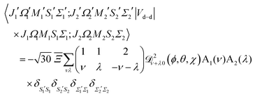 | (A2) |
where| | A1(ν) = 〈J1′Ω1′M1′|![[scr D, script letter D]](https://www.rsc.org/images/entities/char_e523.gif) 1−ν0(ϕ1, θ1, χ1)|J1Ω1M1〉 1−ν0(ϕ1, θ1, χ1)|J1Ω1M1〉 | (A3) |
| | A2(λ) = 〈J2′Ω2′M2′|![[scr D, script letter D]](https://www.rsc.org/images/entities/char_e523.gif) 1−λ0(ϕ2, θ2, χ2)|J2Ω2M2〉 1−λ0(ϕ2, θ2, χ2)|J2Ω2M2〉 | (A4) |
Above and below we make use of the Wigner 3-J symbols instead of the Clebsh–Gordon coefficients,
| |  | (A5) |
as well as of the identities
| | ![[scr D, script letter D]](https://www.rsc.org/images/entities/char_e523.gif) JMΩ(ω)† = (−1)M−Ω JMΩ(ω)† = (−1)M−Ω![[scr D, script letter D]](https://www.rsc.org/images/entities/char_e523.gif) J−M−Ω(ω), J−M−Ω(ω), | (A6) |
| |  | (A7) |
and
| |  | (A8) |
where we abbreviated (
ϕ,
θ,
χ) as (
ω).
From eqn (A3), (A7) and (A8) we then obtain:
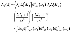
| | 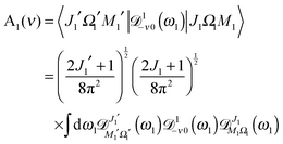 | (A9) |
and
| |  | (A10) |
By making use of the “triple product theorem,”
| |  | (A11) |
eqn (A9) and (A10) reduce to
| |  | (A12) |
and
| |  | (A13) |
and so the complete electric dipole–dipole matrix element becomes:
| | 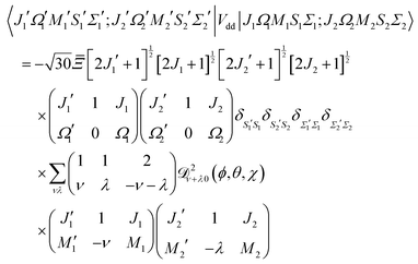 | (A14) |
The various mathematical identities used in this derivation are taken from
ref. 67.
Appendix B: matrix elements of the pairwise alignment cosine in the cross product basis set of the two molecules
The matrix element of the pairwise orientation cosine in the cross product Hund's case (a) basis set of the two molecules is given by| | 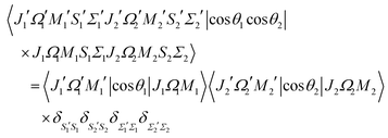 | (B1) |
and the matrix element of the pairwise alignment cosine in the cross product Hund's case (a) basis set of the two molecules is| | 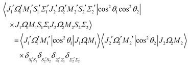 | (B2) |
The matrix elements of SZ, cos![[thin space (1/6-em)]](https://www.rsc.org/images/entities/char_2009.gif) θ and cos2
θ and cos2![[thin space (1/6-em)]](https://www.rsc.org/images/entities/char_2009.gif) θ in the symmetric top basis set are listed in ref. 32.
θ in the symmetric top basis set are listed in ref. 32.
Acknowledgements
Discussions with Mallikarjun Karra as well as support by the Deutsche Forschungsgemeinschaft through grant FR 3319/3-1 are gratefully acknowledged.
References
- A. Slenczka, B. Friedrich and D. Herschbach, Phys. Rev. Lett., 1994, 72, 1806 CrossRef CAS PubMed.
- B. Friedrich, A. Slenczka and D. Herschbach, Can. J. Phys., 1994, 72, 897 CrossRef CAS.
- B. Friedrich and D. Herschbach, J. Chem. Phys., 1999, 111, 6157 CrossRef CAS.
- B. Friedrich and D. Herschbach, J. Phys. Chem. A, 1999, 103, 10280 CrossRef CAS.
- J. Ortigoso, M. Rodrigez, M. Gupta and B. Friedrich, J. Chem. Phys., 1999, 110, 3870 CrossRef CAS.
- T. Seideman, J. Chem. Phys., 1999, 111, 4397 CrossRef CAS.
- T. Seideman, Phys. Rev. Lett., 1999, 83, 4971 CrossRef CAS.
- B. Friedrich and D. Herschbach, Phys. Chem. Chem. Phys., 2000, 2, 419 RSC.
- A. Boca and B. Friedrich, J. Chem. Phys., 2000, 112, 3609 CrossRef CAS.
- J. Larsen, K. Hald, N. Bjerre, H. Stapelfeldt and T. Seideman, Phys. Rev. Lett., 2000, 85, 2470 CrossRef CAS PubMed.
- L. Cai, J. Marango and B. Friedrich, Phys. Rev. Lett., 2001, 86, 775 CrossRef CAS PubMed.
- L. Cai and B. Friedrich, Collect. Czech. Chem. Commun., 2001, 66, 991 CrossRef CAS.
- I. Averbukh and R. Arvieu, Phys. Rev. Lett., 2001, 87, 163601 CrossRef CAS PubMed.
- M. Leibscher, I. Averbukh and H. Rabitz, Phys. Rev. Lett., 2003, 90, 213001 CrossRef CAS PubMed.
- H. Sakai, S. Minemoto, H. Nanjo, H. Tanji and T. Suzuki, Phys. Rev. Lett., 2003, 90, 83001 CrossRef PubMed.
- B. Friedrich, N. H. Nahler and U. Buck, J. Mod. Opt., 2003, 50, 2677 CrossRef CAS.
-
B. Friedrich, in Manipulating cold molecules with non resonant fields, ed. X. Yang and K. Liu, World Scientific, New Jersey and Singapore, 2004, vol. 14, pp. 579–631 Search PubMed.
- M. Leibscher, I. Averbukh and H. Rabitz, Phys. Rev. A: At., Mol., Opt. Phys., 2004, 69, 013402 CrossRef.
- U. Buck and M. Fárnk, Int. Rev. Phys. Chem., 2006, 25, 583 CrossRef CAS.
- M. Härtelt and B. Friedrich, J. Chem. Phys., 2008, 128, 224313 CrossRef PubMed.
- V. Poterya, O. Votava, M. Farnik, M. Oncak, P. Slavicek, U. Buck and B. Friedrich, J. Chem. Phys., 2008, 128, 104313 CrossRef PubMed.
- M. Lemeshko and B. Friedrich, Phys. Rev. A: At., Mol., Opt. Phys., 2009, 79, 012718 CrossRef.
- M. Leibscher and B. Schmidt, Phys. Rev. A: At., Mol., Opt. Phys., 2009, 80, 012510 CrossRef.
- L. Holmegaard, J. H. Nielsen, I. Nevo and H. Stapelfeldt, Phys. Rev. Lett., 2009, 102, 23001 CrossRef PubMed.
- N. Owschimikow, B. Schmidt and N. Schwentner, Phys. Rev. A: At., Mol., Opt. Phys., 2009, 80, 053409 CrossRef.
- Y. Ohshima and H. Hasegawa, Int. Rev. Phys. Chem., 2010, 29, 619–663 CrossRef CAS.
- J. Perez-Rios, F. Herrera and R. V. Krems, New J. Phys., 2010, 12, 103007 CrossRef.
- E. Gershnabel and I. Averbukh, Phys. Rev. Lett., 2010, 104, 153001 CrossRef CAS PubMed.
- N. Owschimikow, F. Königsmann, J. Maurer, P. Giese, A. Ott, B. Schmidt and N. Schwentner, J. Chem. Phys., 2010, 133, 044311 CrossRef CAS PubMed.
- N. Owschimikow, B. Schmidt and N. Schwentner, Phys. Chem. Chem. Phys., 2011, 13, 8671 RSC.
- J. Nielsen, H. Stapelfeldt, J. Küpper, B. Friedrich, J. Omiste and R. González-Férez, Phys. Rev. Lett., 2012, 108, 193001 CrossRef PubMed.
- K. Sharma and B. Friedrich, New J. Phys., 2015, 17, 045017 CrossRef.
- B. Zhao, S. Lee, H. Chung, S. Hwang, W. Kang, B. Friedrich and D. Chung, J. Chem. Phys., 2003, 119, 8905 CrossRef CAS.
- J. Doyle, B. Friedrich, R. Krems and F. Masnou-Seeuws, Eur. Phys. J. D, 2004, 31, 149–164 CrossRef CAS.
- L. D. Carr, D. DeMille, R. V. Krems and J. Ye, New J. Phys., 2009, 11, 055049 CrossRef.
- J. M. Sage, S. Sainis, T. Bergeman and D. DeMille, Phys. Rev. Lett., 2005, 94, 203001 CrossRef PubMed.
- K. Southwell, Nature, 2002, 416, 205 CrossRef.
- H. L. Bethlem, G. Berden, F. M. H. Crompvoets, R. T. Jongma, A. J. A. van Roij and G. Meijer, Nature, 2000, 406, 491–494 CrossRef CAS PubMed.
- B. Friedrich and J. M. Doyle, ChemPhysChem, 2009, 10, 604 CrossRef CAS PubMed.
- E. S. Shuman, J. F. Barry and D. DeMille, Nature, 2010, 467, 820–823 CrossRef CAS PubMed.
- J. F. Barry and D. DeMille, Nature, 2012, 491, 539–540 CrossRef CAS PubMed.
- M. Zeppenfeld, B. G. U. Englert, R. Glockner, A. Prehn, M. Mielenz, C. Sommer, L. D. van Buuren, M. Motsch and G. Rempe, Nature, 2012, 491, 570–573 CrossRef CAS PubMed.
- S. Y. T. van de Meerakker, H. L. Bethlem, N. Vanhaecke and G. Meijer, Chem. Rev., 2012, 112(9), 4828–4878 CrossRef CAS PubMed.
- J. F. Barry, D. J. McCarron, E. B. Norrgard, M. H. Steinecker and D. DeMille, Nature, 2014, 512, 286–289 CrossRef CAS PubMed.
- R. Grimm, M. Weidemüller and Y. N. Ovchinnikov, Adv. At., Mol., Opt. Phys., 2000, 42, 170 Search PubMed.
- I. Bloch, J. Dalibard and W. Zwerger, Rev. Mod. Phys., 2008, 80, 885–964 CrossRef CAS.
- M. Lemeshko, R. V. Krems, J. M. Doyle and S. Kais, Mol. Phys., 2013, 111, 1648–1682 CrossRef CAS.
- J. Jankunas and A. Osterwalder, Annu. Rev. Phys. Chem., 2015, 66, 241–262 CrossRef CAS PubMed.
- A. Micheli, G. Pupillo, H. P. Büchler and P. Zoller, Phys. Rev. A: At., Mol., Opt. Phys., 2007, 76, 043604 CrossRef.
- M. Lemeshko, Phys. Rev. A: At., Mol., Opt. Phys., 2011, 83, 051402 CrossRef.
- M. Lemeshko and B. Friedrich, Mol. Phys., 2012, 110, 1873–1881 CrossRef CAS.
- H. Buechler, E. Demler, M. Lukin, A. Micheli, N. Prokofev, G. Pupillo and P. Zoller, Phys. Rev. Lett., 2007, 98, 060404 CrossRef PubMed.
- A. Micheli, G. Pupillo, H. Buechler and P. Zoller, Phys. Rev. A: At., Mol., Opt. Phys., 2007, 76, 043604 CrossRef.
- H. Buechler, A. Micheli and P. Zoller, Nat. Phys., 2007, 3, 726 CrossRef CAS.
- G. B. A. Micheli and P. Zoller, Nat. Phys., 2006, 2, 341 CrossRef.
- M. Lemeshko and H. Weimer, Nat. Commun., 2013, 4, 2230 CrossRef PubMed.
- M. Lemeshko, Frontiers in Physics—Physical Chemistry Chemical Physics, 2013, 1, 17 Search PubMed.
- N. D. Mermin, Rev. Mod. Phys., 1993, 85, 919 CrossRef.
- M. Karra, K. Sharma, B. Friedrich, S. Kais and D. Herschbach, J. Chem. Phys., 2016, 144, 094301 CrossRef PubMed.
- D. DeMille, Phys. Rev. Lett., 2002, 88, 067901 CrossRef CAS PubMed.
- Q. Wei, S. Kais, B. Friedrich and D. Herschbach, J. Chem. Phys., 2011, 134, 124107 CrossRef PubMed.
- J. Zhu, S. Kais, Q. Wei, D. Herschbach and B. Friedrich, J. Chem. Phys., 2013, 138, 024104 CrossRef PubMed.
- Q. Wei, S. Kais, B. Friedrich and D. Herschbach, J. Chem. Phys., 2011, 135, 154102 CrossRef PubMed.
-
H. Lefebvre-Brion and R. Field, The spectra and dynamics of diatomic molecules, Elsevier, Amsterdam, 2004 Search PubMed.
-
P. R. Bunker and P. Jensen, Fundamentals of Molecular Symmetry, Institute of Physics Publishing, Bristol and Philadeplhia, 2005 Search PubMed.
-
R. N. Zare, Angular momentum: understanding spatial aspects in chemistry and physics, Wiley-Interscience, 2013 Search PubMed.
-
D. Varshalovich, A. Moskalev and V. Khersonski, Quantum theory of angular momentum, World Scientific, New Jersey, London, Singapore, 2008 Search PubMed.
- C. Sanderson, Technical Report, NICTA, 2010, 41, 1–15 Search PubMed.
- S. Joo, D. R. Worsnop, C. E. Kolb, S. K. Kim and D. R. Herschbach, J. Phys. Chem., 1999, 103, 3193 CrossRef CAS.
- D. Feller, J. Comput. Chem., 1996, 17, 1571–1586 CrossRef CAS.
- K. L. Schuchardt, B. T. Didier, T. Elsethagen, L. Sun, V. Gurumoorthi, J. Chase, J. Li and T. L. Windus, J. Chem. Inf. Model., 2007, 47, 1045–1052 CrossRef CAS PubMed.
- W. K. Wootters, Phys. Rev. Lett., 1998, 80, 2245 CrossRef CAS.
|
| This journal is © the Owner Societies 2016 |
 Open Access Article
 the magnetic field strength.


![[Fraktur D]](https://www.rsc.org/images/entities/char_e181.gif) JM,Ω(ϕ, θ, χ) the Wigner matrix, with ϕ, θ, χ the Euler angles, and α, β the spin functions. Thus for a field-free 2Σ state, there are two types of Hund's case (b) basis functions
JM,Ω(ϕ, θ, χ) the Wigner matrix, with ϕ, θ, χ the Euler angles, and α, β the spin functions. Thus for a field-free 2Σ state, there are two types of Hund's case (b) basis functions


 .
.![[J with combining tilde]](https://www.rsc.org/images/entities/i_char_004a_0303.gif) , M; ηm〉 of a 2Σ molecule adiabatically correlate with the field-free rotor states |N, J, M〉 such that |Ñ,
, M; ηm〉 of a 2Σ molecule adiabatically correlate with the field-free rotor states |N, J, M〉 such that |Ñ, ![[J with combining tilde]](https://www.rsc.org/images/entities/i_char_004a_0303.gif) , M; ηm → 0〉 → |N, J, M〉, where Ñ and
, M; ηm → 0〉 → |N, J, M〉, where Ñ and ![[J with combining tilde]](https://www.rsc.org/images/entities/i_char_004a_0303.gif) are adiabatic labels rather than quantum numbers. The projection quantum number M and the parity (−1)Ñ remain good quantum number even in the presence of the Zeeman field. The effects of the magnetic field on 2Σ molecules have been discussed in greater detail, e.g., in ref. 8 and 32.
are adiabatic labels rather than quantum numbers. The projection quantum number M and the parity (−1)Ñ remain good quantum number even in the presence of the Zeeman field. The effects of the magnetic field on 2Σ molecules have been discussed in greater detail, e.g., in ref. 8 and 32.


 , and ε0 is the permittivity of the vacuum. As usual, r1,2 ≡ |r1,2| and μi ≡ |μi| (with i = 1, 2). Moreover, in our case, μ1 = μ2 ≡ μ.
![[scr D, script letter D]](https://www.rsc.org/images/entities/char_e523.gif) lm0(ϕ, θ, χ):
lm0(ϕ, θ, χ):

 measures the strength of the electric dipole–dipole interaction in terms of the rotational constant.

 for molecules 1 and 2 (shown in blue). Hence Mi ranges from −Ji to Ji while
  . Same applies to primed quantities. Note that for instance J1 = J2 = ½ = J1′ = J2′ give rise to a 16 × 16 sub-matrix (shown in green). The size of the blocks increases with J1 and J2, since Mi = −Ji, −Ji + 1,…Ji (i = 1, 2). Note that due to the coupling with the external magnetic field and the intermolecular interaction, the Hamiltonian matrix is not block diagonal. The dots stand for blocks of the matrix. See text.
 . For Jmin = ½ and
  , this means that the truncated Hamiltonian matrix is of a 1600 rank. We note that while there is no apparent difference in the sparsity of the Hamiltonian matrices in Hunds case (a) and (b) basis sets, the computation of the Hund's case (a) matrix elements is about four-times faster than that of the Hunds case (b) matrix elements.
![[J with combining tilde]](https://www.rsc.org/images/entities/i_char_004a_0303.gif) 1, Ñ1,
1, Ñ1, ![[M with combining tilde]](https://www.rsc.org/images/entities/i_char_004d_0303.gif) 1;
1; ![[J with combining tilde]](https://www.rsc.org/images/entities/i_char_004a_0303.gif) 2, Ñ2,
2, Ñ2, ![[M with combining tilde]](https://www.rsc.org/images/entities/i_char_004d_0303.gif) 2; ηm〉 = |
2; ηm〉 = |![[J with combining tilde]](https://www.rsc.org/images/entities/i_char_004a_0303.gif) 1, Ñ1,
1, Ñ1, ![[M with combining tilde]](https://www.rsc.org/images/entities/i_char_004d_0303.gif) 1; ηm〉 |
1; ηm〉 |![[J with combining tilde]](https://www.rsc.org/images/entities/i_char_004a_0303.gif) 2, Ñ2,
2, Ñ2, ![[M with combining tilde]](https://www.rsc.org/images/entities/i_char_004d_0303.gif) 2; ηm〉
2; ηm〉![[J with combining tilde]](https://www.rsc.org/images/entities/i_char_004a_0303.gif) 1, Ñ1,
1, Ñ1, ![[M with combining tilde]](https://www.rsc.org/images/entities/i_char_004d_0303.gif) 1; ηm〉 and |
1; ηm〉 and |![[J with combining tilde]](https://www.rsc.org/images/entities/i_char_004a_0303.gif) 2, Ñ2,
2, Ñ2, ![[M with combining tilde]](https://www.rsc.org/images/entities/i_char_004d_0303.gif) 2; ηm〉 and the corresponding eigenenergies E1 and E2. The eigenenergy of the two-molecule system is then calculated to be
2; ηm〉 and the corresponding eigenenergies E1 and E2. The eigenenergy of the two-molecule system is then calculated to be![[J with combining tilde]](https://www.rsc.org/images/entities/i_char_004a_0303.gif) 1, Ñ1,
1, Ñ1, ![[J with combining tilde]](https://www.rsc.org/images/entities/i_char_004a_0303.gif) 2 and Ñ2 is plotted in the same colour. The projection quantum numbers M1 and M2 of the individual molecules are good quantum numbers in the absence of the electric dipole–dipole interaction.
2 and Ñ2 is plotted in the same colour. The projection quantum numbers M1 and M2 of the individual molecules are good quantum numbers in the absence of the electric dipole–dipole interaction.
![[J with combining tilde]](https://www.rsc.org/images/entities/i_char_004a_0303.gif) 1 = ½, Ñ1 = 0,
1 = ½, Ñ1 = 0, ![[J with combining tilde]](https://www.rsc.org/images/entities/i_char_004a_0303.gif) 2 = ½, Ñ2 = 0, pair-eigenstates. The eigenstates, labelled in accordance with Table 2, are degenerate in the absence of the electric dipole–dipole interaction (their multiplicity is indicated by the number of bars) but their degeneracy is lifted when Ξ ≠ 0. The A½ ½+ and A½ ½− states adiabatically transform into M1 = M2 = −½ and M1 = M2 = ½ states, respectively, when the magnetic field is applied. Note that the B states maintain their entanglement throughout.
2 = ½, Ñ2 = 0, pair-eigenstates. The eigenstates, labelled in accordance with Table 2, are degenerate in the absence of the electric dipole–dipole interaction (their multiplicity is indicated by the number of bars) but their degeneracy is lifted when Ξ ≠ 0. The A½ ½+ and A½ ½− states adiabatically transform into M1 = M2 = −½ and M1 = M2 = ½ states, respectively, when the magnetic field is applied. Note that the B states maintain their entanglement throughout.
![[J with combining tilde]](https://www.rsc.org/images/entities/i_char_004a_0303.gif) 1 = ½, Ñ1 = 0, 1,
1 = ½, Ñ1 = 0, 1, ![[J with combining tilde]](https://www.rsc.org/images/entities/i_char_004a_0303.gif) 2 = ½, Ñ2 = 1, 0 pair-eigenstates. The eigenstates, labelled in accordance with Table 2, are eight fold degenerate in the absence of electric dipole–dipole interaction but only doubly degenerate when Ξ ≠ 0 (their multiplicity is indicated by the number of bars). This double degeneracy arises because the indistinguishability of two molecules. A½ ½+ and A½ ½− states adiabatically transform into M1 = M2 = −½ and M1 = M2 = ½ states, respectively, when the magnetic field is applied. Note that the B states maintain their entanglement throughout.
2 = ½, Ñ2 = 1, 0 pair-eigenstates. The eigenstates, labelled in accordance with Table 2, are eight fold degenerate in the absence of electric dipole–dipole interaction but only doubly degenerate when Ξ ≠ 0 (their multiplicity is indicated by the number of bars). This double degeneracy arises because the indistinguishability of two molecules. A½ ½+ and A½ ½− states adiabatically transform into M1 = M2 = −½ and M1 = M2 = ½ states, respectively, when the magnetic field is applied. Note that the B states maintain their entanglement throughout.
![[J with combining tilde]](https://www.rsc.org/images/entities/i_char_004a_0303.gif) 1 = ½, Ñ1 = 1,
1 = ½, Ñ1 = 1, ![[J with combining tilde]](https://www.rsc.org/images/entities/i_char_004a_0303.gif) 2 = ½, Ñ2 = 1 pair-eigenstates. The eigenstates, labelled in accordance with Table 2, are degenerate in the absence of the electric dipole–dipole interaction (their multiplicity is indicated by the number of bars) but their degeneracy is lifted when Ξ ≠ 0. A½ ½+ and A½ ½− states adiabatically transform into M1 = M2 = ½ and M1 = M2 = −½ eigenstates, respectively, when the magnetic field is applied. Note that the B states maintain their entanglement throughout.
2 = ½, Ñ2 = 1 pair-eigenstates. The eigenstates, labelled in accordance with Table 2, are degenerate in the absence of the electric dipole–dipole interaction (their multiplicity is indicated by the number of bars) but their degeneracy is lifted when Ξ ≠ 0. A½ ½+ and A½ ½− states adiabatically transform into M1 = M2 = ½ and M1 = M2 = −½ eigenstates, respectively, when the magnetic field is applied. Note that the B states maintain their entanglement throughout.
 states become disentangled when the magnetic field is turned on, while the
  states do not. The concurrence was calculated by the method described in ref. 59.
![[J with combining tilde]](https://www.rsc.org/images/entities/i_char_004a_0303.gif) 1, Ñ1,
1, Ñ1, ![[J with combining tilde]](https://www.rsc.org/images/entities/i_char_004a_0303.gif) 2 and Ñ2 are shown in the same colour. Since M1 and M2 are mixed, see Section III B, the eigenstates are labeled according to the system defined in Table 2.
2 and Ñ2 are shown in the same colour. Since M1 and M2 are mixed, see Section III B, the eigenstates are labeled according to the system defined in Table 2.


![[J with combining tilde]](https://www.rsc.org/images/entities/i_char_004a_0303.gif) 1 = ½, Ñ1 = 1,
1 = ½, Ñ1 = 1, ![[J with combining tilde]](https://www.rsc.org/images/entities/i_char_004a_0303.gif) 2 = ½, Ñ2 = 0, B½ ½+; green curve:
2 = ½, Ñ2 = 0, B½ ½+; green curve:  .
.![[thin space (1/6-em)]](https://www.rsc.org/images/entities/char_2009.gif) θ1
θ1![[thin space (1/6-em)]](https://www.rsc.org/images/entities/char_2009.gif) cos
cos![[thin space (1/6-em)]](https://www.rsc.org/images/entities/char_2009.gif) θ2 and pairwise orientation cosine cos2
θ2 and pairwise orientation cosine cos2![[thin space (1/6-em)]](https://www.rsc.org/images/entities/char_2009.gif) θ1
θ1![[thin space (1/6-em)]](https://www.rsc.org/images/entities/char_2009.gif) cos2
cos2![[thin space (1/6-em)]](https://www.rsc.org/images/entities/char_2009.gif) θ2 operators, see also.50,51 The requisite matrix elements for calculating the pairwise cosines are listed in Appendix B.
θ2 operators, see also.50,51 The requisite matrix elements for calculating the pairwise cosines are listed in Appendix B.
![[J with combining tilde]](https://www.rsc.org/images/entities/i_char_004a_0303.gif) 1 = ½, Ñ1 = 1,
1 = ½, Ñ1 = 1, ![[J with combining tilde]](https://www.rsc.org/images/entities/i_char_004a_0303.gif) 2 = ½, Ñ2 = 0, B½ ½+ state (blue curve in Fig. 9) with the
2 = ½, Ñ2 = 0, B½ ½+ state (blue curve in Fig. 9) with the  state (green curve in Fig. 9) at the avoided crossing for Ξ = 10−5 (lower panel) and Ξ = 10−3 (upper panel) at ηm ≈ 0.41775. Note that these states are not oriented but there is a sudden change in alignment of the two molecules at the avoided crossing.
![[J with combining tilde]](https://www.rsc.org/images/entities/i_char_004a_0303.gif) 1 = ½, Ñ1 = 1,
1 = ½, Ñ1 = 1, ![[J with combining tilde]](https://www.rsc.org/images/entities/i_char_004a_0303.gif) 2 = ½, Ñ2 = 0, B½ ½+; green curve:
2 = ½, Ñ2 = 0, B½ ½+; green curve:  .
.![[J with combining tilde]](https://www.rsc.org/images/entities/i_char_004a_0303.gif) 1 = ½, Ñ1 = 1,
1 = ½, Ñ1 = 1, ![[J with combining tilde]](https://www.rsc.org/images/entities/i_char_004a_0303.gif) 2 = ½, Ñ2 = 0, B½ ½+ state (blue curve in Fig. 9) with the
2 = ½, Ñ2 = 0, B½ ½+ state (blue curve in Fig. 9) with the  state (green curve in Fig. 9). The colour coding is the same as in Fig. 9 and 11. We see that the coupling near the avoided crossing changes the alignment of one of the two molecules, which leads to a change in the mutual alignment shown in Fig. 11. For the state
 ![[J with combining tilde]](https://www.rsc.org/images/entities/i_char_004a_0303.gif) 1 = ½, Ñ1 = 1,
1 = ½, Ñ1 = 1, ![[J with combining tilde]](https://www.rsc.org/images/entities/i_char_004a_0303.gif) 2 = ½, Ñ2 = 0, B½ ½+ (blue curve), the alignment of molecule 1 remains constant but the alignment of molecule 2 decreases at the avoided crossing while for the state
2 = ½, Ñ2 = 0, B½ ½+ (blue curve), the alignment of molecule 1 remains constant but the alignment of molecule 2 decreases at the avoided crossing while for the state  the alignment of molecule 1 increases but the alignment of molecule 2 remains constant at the avoided crossing. The relationship between the individual alignment cosines of molecules 1 and 2 and the mutual alignment cosine (for given crossing states) illustrated in Fig. 11 and 12 is rendered by the two-state model below.
![[J with combining tilde]](https://www.rsc.org/images/entities/i_char_004a_0303.gif) 1 = ½, Ñ1 = 1,
1 = ½, Ñ1 = 1, ![[J with combining tilde]](https://www.rsc.org/images/entities/i_char_004a_0303.gif) 2 = ½, Ñ2 = 0, B½ ½+; green curve:
2 = ½, Ñ2 = 0, B½ ½+; green curve:  .
.


 . Since Ξ is inversely proportional to the cube of the distance between the molecules, cf.eqn (11), we see that at large intermolecular separations the eigenenergies of the two molecule system due to electric dipole–dipole interaction vary as r1,2−1.


![[scr D, script letter D]](https://www.rsc.org/images/entities/char_e523.gif) 1−ν0(ϕ1, θ1, χ1)|J1Ω1M1〉
1−ν0(ϕ1, θ1, χ1)|J1Ω1M1〉![[scr D, script letter D]](https://www.rsc.org/images/entities/char_e523.gif) 1−λ0(ϕ2, θ2, χ2)|J2Ω2M2〉
1−λ0(ϕ2, θ2, χ2)|J2Ω2M2〉
![[scr D, script letter D]](https://www.rsc.org/images/entities/char_e523.gif) JMΩ(ω)† = (−1)M−Ω
JMΩ(ω)† = (−1)M−Ω![[scr D, script letter D]](https://www.rsc.org/images/entities/char_e523.gif) J−M−Ω(ω),
J−M−Ω(ω),


![[thin space (1/6-em)]](https://www.rsc.org/images/entities/char_2009.gif) θ and cos2
θ and cos2![[thin space (1/6-em)]](https://www.rsc.org/images/entities/char_2009.gif) θ in the symmetric top basis set are listed in ref. 32.
θ in the symmetric top basis set are listed in ref. 32.


