DOI:
10.1039/C7NJ03040A
(Paper)
New J. Chem., 2018,
42, 48-55
A binder-free paper electrode with high performance for NaBH4 oxidation†
Received
16th August 2017
, Accepted 13th November 2017
First published on 14th November 2017
Abstract
In this study, a piece of filter paper with good flexibility and hygroscopicity was used to support catalysts after a pencil drawing process. A layer of thin Ni film was deposited on the surface of the conductive graphite layer using an electrochemical method at a negative potential. Pd nanoparticles with high electrocatalytic activity for NaBH4 oxidation were introduced by immersing the Ni film-graphite-filter paper (NGF) in PdCl2 solution to obtain a Pd-NGF (PNGF) electrode. The morphology and phase structure of PNGF were characterized using scanning electron microscopy (SEM) equipped with an energy dispersive X-ray spectrometer (EDS), transmission electron microscopy (TEM) and an X-ray diffractometer (XRD). The PNGF electrode was used as the anode in direct borohydride fuel cells (DBFCs), and the electrochemical properties for NaBH4 oxidation were determined by cyclic voltammetry (CV), chronoamperometry (CA) and electrochemical impedance spectroscopy (EIS). The oxidation current density reaches 550 mA cm−2 at −0.4 V when the electrolyte contains 2 mol dm−3 NaOH and 0.10 mol dm−3 NaBH4.
1. Introduction
Fuel cells (FCs) operating with sodium borohydride (NaBH4) as fuel tend to be better than those directly using hydrogen as fuel due to their high energy density (9.3 W h g−1), high hydrogen content (10.6 wt%), good chemical stability in alkaline solution, non-toxicity and non-CO2 emission, and the easy handling of NaBH4.1–6 Direct borohydride fuel cells (DBFCs) have attracted much attention with the rapid depletion of fossil fuels, such as coal and petroleum. BH4− electrooxidation plays a key role for the application of FCs. Besides, the complete electrooxidation of BH4− will release 8e− (eqn (1)),1–7 which is much higher than that of some other fuels including NH3BH3 (6e−),8 N2H4 (4e−)9 and H2O2 (2e−),10etc. Noble metals (e.g., Pt,11–15 Pd,11,16–20 Au,11,12,21–29 Ag,30–33 Os,34etc.), transition metals (e.g., Co,35 Ni,11,36 Cu,37 Zn,38etc.) and hydrogen storage alloys29,39–41 have been proved to be efficient catalysts for BH4− electrooxidation. For example, Aksu et al.7,11,21,30–32 investigated the electrooxidation behavior of NaBH4 on Pt, Pd Au, Ni and Ag electrodes; Gyenge et al.12,22,34 studied the catalytic mechanism of noble metals such as Pt, Au and Os for NaBH4 electrooxidation; Wang et al.13,16,23,24 prepared various Pt, Pd and Au materials with a special structure and composition for the electrooxidation of NaBH4; Liu and Li14,17 studied different carbon (activated carbon, carbon black, multi-walled carbon nanotubes, Cabot Vulcan XC72, carbon aerogel and macroporous carbon) supported nano Pt and Pd catalysts; Wang et al.29,39,40 modified hydrogen alloys with Au, Si, Ti and Zr; Duan et al.18,25,33 fabricated some alloys with a core–shell structure, all of which had impressive electrocatalytic activity for BH4− oxidation in alkaline solution; our team15,19,27,28 fabricated 3D porous nano-wires/sheets/network based Pt, Pd and Au electrodes for BH4− electrooxidation, in which a hydrothermal method and chemical vapor deposition were used to prepare Co3O4 and C@TiO2 supports, followed by simple electrodeposition and galvanic replacement for the deposition of catalysts.15,19 It is worth noting that the oxidation current density of PtCo/Co3O4 reached 850 mA cm−2 in 2 mol dm−3 NaOH and 0.2 mol dm−3 NaBH4 at −0.4 V,15 which was higher than that reported in most of the previous studies.| | | BH4− + 8OH− → BO2− + 6H2O + 8e− | (1) |
At present, flexible electrode materials, especially paper based electrodes,42–49 have become a topic of considerable research interest due to strong demand for electronic devices with deformability. Normal paper modified using conductive materials such as single metals (e.g., Co, Ag and Ni),35,44,45 carbon materials (e.g., CNTs, graphite and graphene)44–47 and polymers (e.g., PANi and PPy)48,49 through coating, electrodeposition and chemical polymerization have served as electrode supports in electrochemical devices. These electrodes showed good flexibility, high stability and excellent electrocatalytic activity. Graphite coating is one of the simplest and most efficient ways to construct a highly conductive paper support with low cost. Recently, Li et al.45 fabricated conductive paper by a handwriting process using a common 8B-type pencil purchased from stationery shop. More importantly, they deposited a thin Ni film on the paper surface at a negative potential to improve the conductivity of graphite coated paper, after which a MnO2 layer was electrodeposited on the surface of the Ni film. They found that the electrodes with Ni film modified paper exhibited better electrochemical performance than those with pure graphite-paper supported active materials. In addition, a 3D PANi network was electrodeposited on the surface of graphite modified paper to store energy.46 Very recently, we coated a layer of graphite on a piece of normal A4 paper using a similar coating process. Binder-free conductive paper is of lower cost in contrast to MWNT modified electrodes and was used to support the nano-Co sheets.35 At −0.4 V, this cobalt-graphite-paper had an oxidation current density of 180 mA cm−2 in a solution containing 1 mol dm−3 NaOH and 0.10 mol dm−3 NaBH4. Although the electrode is not expensive, its electrocatalytic activity for NaBH4 oxidation is lower than that of noble metals such as Pt, Pd, Au and Ag. Besides, the transition metal Co is a strategic metal with a relatively low reserve and high cost compared with other transition metals like Fe, Ni and Zn. Thus, it is of critical importance to develop new catalysts based on graphite modified paper with good mechanical properties and higher electrocatalytic activity for NaBH4 electrooxidation in DBFCs.
Filter paper has better flexibility than normal A4 paper. Its strong hygroscopicity can contribute to diffusion of fuel and electrolytes in FCs, resulting in increased contact between the fuel and catalysts and consequently leading to a higher catalytic activity. Thus, filter paper may be a good choice as an electrode support in FCs. In this study, a graphite layer was coated on a piece of filter paper, which served as the conductive substrate to support the Ni film deposited by the electrochemical method. Considering the fact that BH4− electrooxidation always involves the breakage of the B–H bond,5 Pt, Pd, Ni, Co and their alloys that have been proved to be efficient in breaking B–H bonds can be good choices for BH4− electrooxidation. In this study, we combined Pd and Ni in an attempt to improve the performance for NaBH4 oxidation. Pd nanoparticles are uniformly distributed on the surface of the Ni film by a simple galvanic replacement process in PdCl2 solution. The obtained Pd–Ni film-graphite-filter paper (PNGF) electrode has a high electrochemical performance of 550 mA cm−2 in 2 mol dm−3 NaOH solution containing 0.10 mol dm−3 NaBH4 at −0.2 V, which is much higher than that on the as-prepared cobalt-graphite-paper35 under the same conditions. This can be attributed to the high activity of the noble metal Pd and the synergistic effect of the Pd–Ni alloy. The high catalytic activity, good stability and flexibility make the PNGF electrode a promising anode material in DBFCs.
2. Experimental
2.1 Fabrication and electrochemical measurement of the PNGF electrode
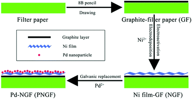
The PNGF electrode was fabricated via four steps as shown in Fig. 1. Firstly, an 8B pencil (Shanghai Yinzun Company) was used for handwriting on filter paper (Yantai New Universal Filtration Equipment Co. Ltd, China) to form the conductive substrate after iterative drawing for the following electrodeposition process. Fig. S1 (ESI†) shows the optical images of the bare filter paper (a) with its SEM image (the inset) and the GF substrate (b). Here, the coarse filter paper surface with some interlaced lines serves as a sieve, on which graphite is filtered and leaves a conductive mark through the scratching process. Secondly, the graphite coated filter paper (GF) was cut into pieces of 1 cm × 1 cm (1 cm2 planar area) and then immersed into a solution containing 2 mol dm−3 NH4Cl and 0.10 mol dm−3 NiCl2. A high potential of 1.0 V was applied for 20 min to activate the coated graphite and obtain a hydrophilic surface, followed by a constant potential of −1.0 V for 60 min to deposit the metallic Ni film on the GF surface. Finally, the Ni film-GF (NGF) served as the support to sustain Pd nanocatalysts by a simple chemical reduction method in PdCl2 solution (eqn (2)). The replacement time was regulated to obtain Pd-NGF (PNGF) electrodes with different Pd loadings and good electrochemical performance for BH4− oxidation. These electrochemical processes were carried out in a common three-electrode system on an Autolab PGSTAT302 (Eco Chemie) electrochemical workstation using GF as the working electrode, a saturated Ag/AgCl, KCl electrode as the reference electrode and Pt foil as the counter electrode. The following electrochemical tests were performed on the same instrument using PNGF as the working electrode.
 |
| | Fig. 1 The fabrication process of the PNGF electrode. | |
2.2 Characterization of materials
The morphology and structure of the as-prepared PNGF were characterized using a scanning electron microscope (SEM, JEOL JSM-6480) equipped with an energy dispersive X-ray spectrometer (EDS), a transmission electron microscope (TEM, FEI TeccaiG2S-Twin, Philips) and a powder X-ray diffractometer (XRD, Rigaku TTR-III) equipped with Cu Kα radiation (λ = 0.15406 nm). For the preparation of TEM samples, Ni and NiPd catalysts were scrapped off from the as-prepared NGF and PNGF and dispersed uniformly in two ethanol solutions by ultrasonic treatment, respectively. Then the two suspensions were added onto Lacey support films dropwise. The loading amount of Pd was determined using an inductively coupled plasma emission spectrometer (ICP, Xseries II, Thermo Scientific).
3. Results and discussion
3.1 SEM, EDS and TEM characterization of the materials
Fig. 2 shows the SEM images of the NGF support (a and b), the PNGF electrode (c and d) and the GF substrate (the inset of Fig. 2(a)). The TEM images of the Ni and Pd–Ni films are shown in Fig. 2(b) and (d), respectively. The inset image in Fig. 2(a) shows the SEM image of the bare GF substrate, which shows that the graphite layer is composed of many graphite sheets. This not only makes the filter paper conductive, which is essential for the component of the electrode material, but also allows it to serve as the transition and support layer for the electrodeposition of the Ni film. The low-magnification SEM image of the Ni film (a) shows that the Ni film consists of large Ni particles with a diameter of >1 μm, while the high-magnification image (b) shows that the surface of the Ni particles is rough rather than being highly smooth, which will increase the specific surface area of the catalysts and is good for the electrochemical reaction. In order to further clarify the surface state of the Ni particles, a TEM image of a single Ni particle is displayed in the inset of Fig. 2(b). Clearly, the diameter of the Ni particle is >1 μm, which is consistent with that in the SEM image as shown in Fig. 2(a). Besides, the surface of the Ni particle is somewhat rough with reference to the different shades of color in the planar Ni particle. The sheet resistance decreases from 20 to less than 0.10 Ω square−1 after the deposition of the Ni film, which is consistent with the results of Li et al.45 This can ensure an efficient transfer of electrons in the subsequent electrochemical tests. The loading mass of graphite and Ni is around 0.6 and 6 mg cm−2, respectively. Moreover, the Ni film can also serve as a protective layer to reduce the extent of damage to the filter paper in the reaction process. Fig. 2(c) and (d) show the high- and low-magnification SEM images of the PNGF electrode. Compared with the NGF support, some nanoparticles are observed on the surface of the PNGF electrode and the surface becomes much rougher due to the introduction of Pd. It is noted that the SEM image of the PNGF electrode is clearer than that of the NGF support, indicating that the existence of Pd improves the electrical conductivity of the as-prepared materials. The TEM image of the Pd–Ni film shows that the Pd particles are in the nanoscale and distributed uniformly on the surface of the Ni film. The loading mass of Pd on the PNGF electrode measured by ICP is around 0.076 mg cm−2.
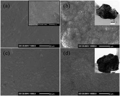 |
| | Fig. 2 The SEM images of the NGF support (a and b) and the PNGF electrode (c and d) and the GF substrate (the inset of a), and TEM images of Ni (the inset of b) and Pd–Ni films (the inset of d). | |
XRD measurements (Fig. 3) were employed to analyze the structure of GF, NGF and PNGF. The GF substrate exhibits seven obvious diffraction peaks and many weaker diffraction peaks in the range of 10–90°, which can be attributed to the carbon of the graphite in the pencil lead, some other complex components like wood cellulose that provide good hygroscopicity and filterability, and some impurities introduced during the preparation process. It is noted that filter paper, which is mainly produced from wood, is renewable and environmental friendly. Three new and strong diffraction peaks appear at 2θ values of 44.8°, 52.0° and 76.7°, which can be indexed to the (1 1 1), (2 0 0) and (2 2 0) planes of Ni (JCPDS card no. 04-0850), respectively. The coating of the Ni film results in a sharp decrease in the diffraction peak intensities of the GF substrate, indicating that metallic Ni is successfully deposited on the GF surface and covers the graphite layer. However, no new diffraction peak is observed after the chemical reduction of Pd in the XRD pattern of the PNGF electrode. In fact, the diffraction peak intensity of metallic Ni, whose loading mass on the GF substrate is almost 80 times larger than that of the noble metal Pd, is much stronger than that of Pd and masks the diffraction peaks of Pd with a low content.
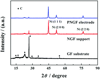 |
| | Fig. 3 The XRD patterns of GF, NGF and PNGF. | |
EDS is a useful strategy to identify element diffusion on the electrode surface. The Pd element cannot be detected using XRD since its content is low, so ICP and EDS are employed to verify the formation of Pd after the immersion of NGF into Pd2+ solution. Fig. 4 shows the SEM image of the PNGF electrode (a), the corresponding elemental distributions of C (b), Ni (c) and Pd (d), and the EDS spectrum (e). Fig. 4(a) shows that the active layer is uniformly distributed on the surface of the filter paper; Fig. 4(b) shows that the carbon element is loosely distributed on the electrode surface, demonstrating that most of the graphite layer is coated by the Ni film and only a small amount of carbon is detected, which may exist in the gaps of the Ni particles. Accordingly, the electrode surface is almost completely covered by the Ni element (b). The Pd element can also be detected on the PNGF surface as shown in Fig. 4(c), indicating that the galvanic replacement method is a valid way to prepare Pd-containing materials. The corresponding EDS spectrum (e) of the PNGF electrode demonstrates that the amount of Pd is much lower than that of Ni, which explains why Pd cannot be detected by the XRD pattern (Fig. 3), and confirms the ICP measurement results.
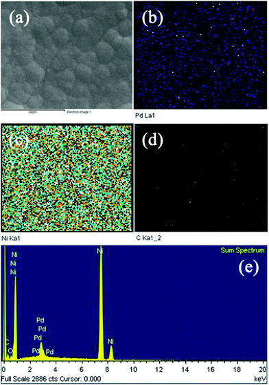 |
| | Fig. 4 The SEM image of the PNGF electrode (a), the corresponding elemental distributions of C (b), Ni (c) and Pd (d), and the EDS spectrum (e). | |
3.2 The study of NaBH4 electrooxidation behavior
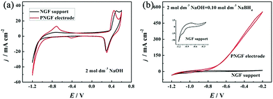
The electrochemical properties of the GF substrate, NGF support and PNGF in NaOH solution with and without NaBH4 are shown in Fig. S2 (ESI†), Fig. 5 and Fig. S3 (ESI†), respectively. As seen in Fig. S2 (ESI†), the GF substrate has a double-layer capacitance in the sweep range of −1.2 to −0.2 V with no obvious oxidation/reduction peaks in the cyclic voltammogram (CV) curves, indicating that conductive graphite with capacitive performance has been coated on the filter paper surface and it is also stable in an alkaline environment. The deformability, electrical conductivity and stability in the NaOH electrolyte make GF a good substrate to support the electrocatalysts in the following study. After adding NaBH4 to NaOH solution, a pair of redox peaks appear between −1.1 and −0.8 V, which can be attributed to the adsorption and desorption of hydrogen35 generated from the hydrolysis of BH4− (eqn (3)).1–6 In fact, carbon materials have been proved to be able to adsorb hydrogen50,51 to improve BH4− electrooxidation in some of our published reports27,41 by adsorbing and re-oxidizing hydrogen released from hydrolysis (eqn (3)) and incomplete electrooxidation of BH4− (eqn (4)).41 Therefore, the existence of graphite on the electrode surface can improve the electrocatalytic performance towards BH4− oxidation. Fig. 5 shows the CV curves of the NGF support and the PNGF electrode in 2 mol dm−3 NaOH without (a) and with (b) 0.10 mol dm−3 NaBH4. In the NGF support, a pair of redox peaks is observed between 0.2 and 0.5 V, which corresponds to the conversion of Ni2+ and Ni3+ at a high potential, respectively (a).36 From the enlarged view of the CV curve of the NGF support in a solution containing NaOH and NaBH4 (b), a new oxidation peak is observed at around −0.8 V, which is not obtained in bare NaOH solution and is indexed to the electrooxidation of adsorbed hydrogen. The current density is much higher than that of the CVs of NGF in bare NaOH solution and the GF substrate in a mixed solution in the whole scanning range, indicating that the Ni film has a positive catalytic activity for BH4− electrooxidation. After chemical reduction in PdCl2 solution, Pd nanoparticles have been successfully introduced into the PNGF electrode, as evidenced by SEM, TEM, EDS and ICP results. Fig. 5(a) further shows that an electrooxidation peak with a current density of about 15 mA cm−2 appears at around −0.8 V in the CV using PNGF as the electrode in NaOH solution, which may be caused by the electrooxidation of hydrogen at Pd catalysts. More importantly, the oxidation current density reaches 550 mA cm−2 at −0.4 V when the electrolyte contains 2 mol dm−3 NaOH and 0.10 mol dm−3 NaBH4 (b). Pd has a strong ability in breaking the B–H bond in BH4−, leading to high electrocatalytic performance. Fig. S3 (ESI†) shows the EIS of the GF substrate, NGF support and PNGF in NaOH solution without (a) and with (b) NaBH4 at −0.3 V. The inset in (b) is the enlarged view of EIS of PNGF in 2 mol dm−3 NaOH and 0.1 mol dm−3 NaBH4. Clearly, the three materials show different Nyquist plots. The PNGF and NGF support have smaller diameters of the semicircle than the GF substrate in both solutions, demonstrating that the PNGF and NGF support have lower charge transfer resistance. Compared with the NGF support, the introduction of Pd reduces the charge transfer resistance for PNGF due to its high electronic conductivity and leads to a much smaller semicircle. After the addition of fuel, the charge transfer resistance of PNGF exhibits a sharp decrease compared to that tested in bare NaOH solution, which can be attributed to the electrooxidation of BH4− and demonstrates the much higher catalytic activity of PNGF compared with the NGF support and the GF substrate. All these results show that Pd has been attached to the electrode surface, and PNGF is a promising electrode material with high activity for NaBH4 electrooxidation.| | | BH4− + 2H2O → BO2− + 4H2 | (3) |
| | | BH4− + xOH− → BO2− + (x − 2)H2O + (4 − x/2)H2 + xe− | (4) |
According to Fig. 5(b), Pd plays a major role in electrocatalytic reactions, and thus the chemical reduction time, which can affect the content of Pd, has a great effect on BH4− electrooxidation. Fig. S4 (ESI†) gives the CVs of PNGF electrodes with an increase of the galvanic replacement time from 5 to 60 s in 2 mol dm−3 NaOH and 0.10 mol dm−3 NaBH4 from −1.2 to −0.2 V at a scan rate of 20 mV s−1. It is clear that the oxidation current density increases as the immersion time in PdCl2 solution increases from 5 to 30 s, and then decreases with further increase in immersion time. This is probably because although Pd can improve the catalytic performance, a very high Pd content may lead to aggregation and thus reduce the active sites and the utilization efficiency of catalysts on PNGF.
 |
| | Fig. 5 The CV curves of the NGF support and the PNGF electrode in NaOH without (a) and with (b) NaBH4. The inset in (b) is the enlarged view of the CV curve of the NGF support in the solution containing NaOH and NaBH4. Scan rate: 20 mV s−1, NaOH: 2 mol dm−3, NaBH4: 0.10 mol dm−3. | |
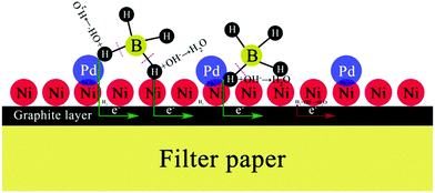
Both OH− and BH4− take part in the electrooxidation reaction (eqn (1)). Thus, it is necessary to study the effects of OH− and BH4− concentrations on electrochemical reactions to better understand the electrode performance for BH4− electrooxidation, and the results are shown in Fig. 6(a) and (b), respectively. It should be pointed out that NaOH not only provides OH− for the electrooxidation reaction with BH4−, but also serves as a supporting electrolyte in this electrochemical system. The oxidation current density increases with an increase of the NaOH concentration from 1 to 2 mol dm−3, because more OH− can facilitate the electrooxidation reaction towards the positive direction. However, the catalytic performance decreases as the OH− concentration increases from 3 to 5 mol dm−3. At this time, a large amount of OH− is adsorbed on the PNGF surface and occupies the active sites of the catalysts, which can hinder the contact of BH4− and the catalysts and thus lead to a decreased catalytic performance, as shown in Fig. 6(a). The CVs of the PNGF electrode in 2 mol dm−3 NaOH with various NaBH4 concentrations (0.05–4 mol dm−3) at a scan rate of 20 mV s−1 are shown in Fig. 6(b). At −0.2 V, the current density is 284, 558, 643, 702 and 719 mA cm−2 with a NaBH4 concentration of 0.05, 0.10, 0.20, 0.30 and 0.40 mol dm−3, respectively, indicating that more BH4− reacts with OH− with the increase of NaBH4 concentration. However, the difference in the oxidation current densities between two adjacent CVs gradually decreases with the addition of NaBH4 under the same conditions. The extent of BH4− hydrolysis is reinforced, and more hydrogen is released and adsorbed on the electrode surface with the addition of NaBH4, which has an adverse effect on the contact between the fuel and catalysts and consequently hinders the improvement in catalytic performance. Based on the above results, the solution containing 2 mol dm−3 NaOH and 0.1 mol dm−3 NaBH4 is the best choice among the tested concentrations. The catalytic performance of PNGF is much higher than that of Pd20 and Au29 modified AB5-type hydrogen storage alloys fabricated by “slurrying and coating” and galvanic replacement methods, graphene coated Ni foam supported Au (reduced graphene networks-Au) electrodes prepared by “dipping and drying” and electrodeposition,27 Ni foam based Au prepared by chemical reduction in AuCl3 solution,28 and the previous flexible graphite modified paper based Co electrode (cobalt-graphite-paper)35 prepared by similar handwriting and electrodeposition methods for NaBH4 electrooxidation. Detailed comparison of the electrocatalytic performance for the as-prepared PNGF electrode, some binder-containing electrodes and simple substance catalysts is shown in Table 1. The possible connections between the structure of the catalyst active sites and their reactivity are illustrated in Fig. 7, and the superior electrocatalytic performance may result due to the following factors: (1) Pd has a strong ability to break the B–H bond in BH4−, which is the precondition for BH4− electrooxidation, and hydrogen was further electrooxidized to release electrons; (2) nano-dimensional Ni acts as the electrocatalyst to break the B–H bond and catalytic hydrogen oxidation, and generate electrons, which is different from the Ni foam based electrode; (3) the synergistic effect of catalyst alloys and the special path for the transfer of electrons have a positive effect on the electrochemical reactions and more electrons were released, which is better than single metal catalysts;24,52 (4) as discussed before (Fig. S2, ESI†), graphite may adsorb some hydrogen and release some electrons by electrooxidization; and (5) no polymer binder is used in the preparation of PNGF, which can ensure high conductivity and avoid the peeling of catalysts from the substrate surface. Thus, a good stability can be expected during the tests. Besides, PNGF is particularly advantageous over the normal metal-plate based electrode due to its good flexibility. It is also necessary to point out that two obvious oxidation peaks appear when the NaOH concentration is as high as 5 mol dm−3 or the NaBH4 concentration is as low as 0.05 mol dm−3 (Fig. 6). One at about −0.3 V during the positive scan is attributed to the direct electrooxidation of BH4−. The other one at about −0.5 V during the negative scan is associated with the indirect electrooxidation of its intermediate products (e.g., BH3OH*, BH2OH*, BHOH*, etc., where “*” represents the adsorbed state)5 produced from the incomplete oxidation of BH4−. The two oxidation peaks become more pronounced at lower scan rates such as 2, 5 and 10 mV s−1 (Fig. S5, ESI†). The high NaOH concentration and low NaBH4 concentration will reduce the fuel concentration on the electrode surface, and the low scan rate will increase the consumption of fuel. Under both conditions, the reaction is controlled by diffusion, causing the appearance of oxidation peaks. One chemical reaction (hydrolysis of BH4−) and three electrochemical reactions (direct electrooxidation of BH4−; indirect electrooxidation of the intermediate products; and electrooxidation of hydrogen) occur on the active sites of the electrode.
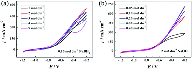 |
| | Fig. 6 The CVs of the PNGF electrode in 0.10 mol dm−3 NaBH4 with different concentrations of NaOH (1–5 mol dm−3) (a); and 2 mol dm−3 NaOH with different concentrations of NaBH4 (0.05–0.40 mol dm−3) (b). | |
Table 1 Comparison of the electrocatalytic performance for the PNGF and other previously reported electrodes
| Electrodes |
OH− concentration (mol dm−3) |
BH4− concentration (mol dm−3) |
Potential (V) |
Current density (mA cm−2) |
Ref. |
| AB5 hydrogen storage alloy-Pd |
0.5 |
0.1 |
−0.1 |
Around 115 |
20
|
| Reduced graphene networks-Au |
2 |
0.1 |
0 |
500 |
27
|
| Au–Ni foam |
2 |
0.2 |
−0.4 |
80 |
28
|
| AB5 hydrogen storage alloy-Au |
2 |
1 |
−0.4 |
Around 720 |
29
|
| Cobalt-graphite-paper |
1 |
0.1 |
−0.4 |
180 |
35
|
| PNGF |
2 |
0.1 |
−0.4 |
550 |
This work |
 |
| | Fig. 7 The possible reaction mechanism of BH4− electrooxidation on the PNGF electrode. | |
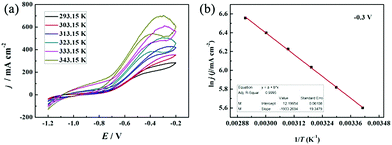
FCs having strong adaptability and high performance, especially at high working temperatures, can satisfy the requirement of electrochemical devices operable under extreme conditions. Thus, we investigated the effect of reaction temperature on the electrochemical performance of the PNGF electrode in the solution containing 2 mol dm−3 NaOH and 0.1 mol dm−3 NaBH4 (Fig. 8(a)). Clearly, increasing the reaction temperature can increase the catalytic performance (the oxidation current density) on the premise that it is stable at that temperature. One interesting thing is that the catalysts will not fall off from PNGF and the electrode structure remains intact after the tests at different temperatures. More importantly, PNGF can work at a high temperature of 343.15 K, and thus it has the potential to be used as an electrode material for DBFCs operating at high temperatures. The oxidation current density increases from 270 to 700 mA cm−2 as the operating temperature increases from 293.15 to 343.15 K. The oxidation reactions are accelerated at a high temperature, resulting in an enhanced catalytic performance. Besides, the appearance of oxidation peaks and their negative shift at higher temperatures can be attributed to the large consumption of fuel. The hydrolysis of BH4− is intensified as the temperature increases, and thus more hydrogen gas is released from the electrode surface with the increase of temperature, making the CVs become coarser with the disturbance of hydrogen. Activation energy (Ea) is an important parameter to measure the difficulty of reactions. The lower the Ea value, the easier the reaction. Fig. 8(b) shows the Arrhenius plot of the current densities at −0.3 V for BH4− electrooxidation on the PNGF electrode. The Ea value calculated from the Arrhenius equation (eqn (5))53 is 16.07 kJ mol−1, where j is the current density, T is the thermodynamic temperature, R is the molar gas constant (8.314 J mol−1 K−1), and Ea is the activation energy.
| |  | (5) |
CV is a dynamic electrochemical method to study electrochemical behaviors and kinetics. A static method named chronoamperometry (CA) was used to further evaluate the catalytic activity and stability of PNGF for BH
4− electrooxidation. The CA tests were carried out in 2 mol dm
−3 NaOH and 0.1 mol dm
−3 NaBH
4 at four fixed potentials from −0.6 V to −0.3 V (
Fig. 9), chosen in the scan range of CV curves. These CAs reach a steady state after a sharp decay caused by the electrooxidation of hydrogen or some other adsorbates on the electrode surface in a few seconds. The stable current density increases as the applied potential increases, which is in agreement with the CV results. A higher potential will provide a higher overpotential and driving force, so the possibility and the extent of the electrochemical reactions increase. The CAs become coarser as the applied potential increases, which can be caused by the generation of more hydrogen gas as discussed above. The CAs remain almost stable with no decay during the whole test process, demonstrating the ideal stability of PNGF for BH
4− electrooxidation. Fig. S6 (ESI
†) provides the SEM images of PNGF at low (a) and high (b) magnifications, and the corresponding TEM image (the inset in b) after the electrochemical tests. The results show that the morphologies and microstructures of the used samples after cycling were not destroyed, demonstrating that the as-prepared electrodes have good stability.
 |
| | Fig. 8 The CVs of the PNGF electrode at different operating temperatures (293.15–343.15 K) (a); the Arrhenius plot of the current densities at −0.3 V (b). Scan rate: 20 mV s−1, NaOH: 2 mol dm−3, NaBH4: 0.10 mol dm−3. | |
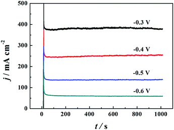 |
| | Fig. 9 The CA curves of PNGF at different applied potentials (−0.6 to −0.3 V). | |
4. Conclusions
A support with deformability is a prerequisite for the fabrication of flexible electrochemical devices. In this study, a PNGF electrode was prepared using a piece of filter paper as the substrate. An 8B pencil was used to coat a layer of graphite on the filter paper surface which serves as the conductive layer (GF), and a Ni film was then electrodeposited on the GF surface to protect the GF, resulting in an increase in the conductivity and catalytic activity. Finally, Pd nanoparticles were prepared by a simple galvanic replacement process to form the working electrode (PNGF). Benefiting from the high electronic conductivity and the improved ability for breaking the B–H bond of metallic Ni, the super catalytic activity of the noble metal Pd, the synergistic effect of Pd–Ni, and a certain hydrogen adsorption ability of the graphite on the paper surface, PNGF is highly effective for BH4− electrooxidation. PNGF can be a novel and promising material in DBFCs and some other fuel cells due to its high electrocatalytic activity, flexibility, stability and environmentally friendliness.
Conflicts of interest
There are no conflicts to declare.
Acknowledgements
This study was funded by the Natural Science Foundation of Shanxi (201701D221047).
Notes and references
- D. M. F. Santos and C. A. C. Sequeira, Renewable Sustainable Energy Rev., 2011, 15, 3980–4001 CrossRef CAS.
- B. H. Liu and Z. P. Li, J. Power Sources, 2009, 187, 291–297 CrossRef CAS.
- C. P. de Leon, F. C. Walsh, D. Pletcher, D. J. Browning and J. B. Lakeman, J. Power Sources, 2006, 155, 172–181 CrossRef.
- I. Merino-Jiménez, C. Ponce de León, A. A. Shah and F. C. Walsh, J. Power Sources, 2012, 219, 339–357 CrossRef.
- G. Rostamikia and M. J. Janik, Energy Environ. Sci., 2010, 3, 1262–1274 CAS.
- P.-Y. Olu, N. Job and M. Chatenet, J. Power Sources, 2016, 327, 235–257 CrossRef CAS.
- A. E. Sanli, M. L. Aksu and B. Z. Uysal, Int. J. Hydrogen Energy, 2011, 36, 8542–8549 CrossRef CAS.
- X.-B. Zhang, S. Han, J.-M. Yan, M. Chandra, H. Shioyama, K. Yasuda, N. Kuriyama, T. Kobayashi and Q. Xu, J. Power Sources, 2007, 168, 167–171 CrossRef CAS.
- G. E. Evans and K. V. Kordesch, Science, 1967, 158, 1148–1152 CAS.
- S.-i. Yamazaki, Z. Siroma, H. Senoh, T. Ioroi, N. Fujiwara and K. Yasuda, J. Power Sources, 2008, 178, 20–25 CrossRef CAS.
- H. Çelikkan, M. Şahin, M. L. Aksu and T. Nejat Veziroğlu, Int. J. Hydrogen Energy, 2007, 32, 588–593 CrossRef.
- E. Gyenge, Electrochim. Acta, 2004, 49, 965–978 CrossRef CAS.
- L. Yi, Y. Song, W. Yi, X. Wang, H. Wang, P. He and B. Hu, Int. J. Hydrogen Energy, 2011, 36, 11512–11518 CrossRef CAS.
- G. R. Li, Q. Q. Wang, B. H. Liu and Z. P. Li, Fuel Cells, 2015, 15, 270–277 CrossRef CAS.
- C. Song, D. Zhang, B. Wang, Z. Cai, P. Yan, Y. Sun, K. Ye, D. Cao, K. Cheng and G. Wang, Nano Res., 2016, 9, 3322–3333 CrossRef CAS.
- L. Yi, Y. Song, X. Wang, L. Yi, J. Hu, G. Su, W. Yi and H. Yan, J. Power Sources, 2012, 205, 63–70 CrossRef CAS.
- J. Q. Yang, B. H. Liu and S. Wu, J. Power Sources, 2009, 194, 824–829 CrossRef CAS.
- D. Duan, X. You, J. Liang, S. Liu and Y. Wang, Electrochim. Acta, 2015, 176, 1126–1135 CrossRef CAS.
- K. Cheng, D. Cao, F. Yang, L. Zhang, Y. Xu and G. Wang, J. Mater. Chem., 2012, 22, 850–855 RSC.
- K. Cheng, Y. Xu, R. R. Miao, F. Yang, J. L. Yin, G. L. Wang and D. X. Cao, Fuel Cells, 2012, 12, 869–875 CrossRef CAS.
- H. Celikkan, H. Aydin and M. L. Aksu, Turk. J. Chem., 2005, 29, 519–524 CAS.
- M. H. Atwan, C. L. B. Macdonald, D. O. Northwood and E. L. Gyenge, J. Power
Sources, 2006, 158, 36–44 CrossRef CAS.
- J. Wei, X. Wang, Y. Wang, Q. Chen, F. Pei and Y. Wang, Int. J. Hydrogen Energy, 2009, 34, 3360–3366 CrossRef CAS.
- P. He, X. Wang, Y. Liu, X. Liu and L. Yi, Int. J. Hydrogen Energy, 2012, 37, 11984–11993 CrossRef CAS.
- D. Duan, J. Liang, H. Liu, X. You, H. Wei, G. Wei and S. Liu, Int. J. Hydrogen Energy, 2015, 40, 488–500 CrossRef CAS.
- P. Yan, D. Zhang, K. Cheng, Y. Wang, K. Ye, D. Cao, B. Wang, G. Wang and Q. Li, J. Electroanal. Chem., 2015, 745, 56–60 CrossRef CAS.
- D. Zhang, G. Wang, Y. Yuan, Y. Li, S. Jiang, Y. Wang, K. Ye, D. Cao, P. Yan and K. Cheng, Int. J. Hydrogen Energy, 2016, 41, 11593–11598 CrossRef CAS.
- D. Cao, Y. Gao, G. Wang, R. Miao and Y. Liu, Int. J. Hydrogen Energy, 2010, 35, 807–813 CrossRef CAS.
- Z. Yang, L. Wang, Y. Gao, X. Mao and C.-A. Ma, J. Power Sources, 2008, 184, 260–264 CrossRef CAS.
- E. Sanlı, H. Çelikkan, B. Zühtü Uysal and M. L. Aksu, Int. J. Hydrogen Energy, 2006, 31, 1920–1924 CrossRef.
- E. Sanli, H. Celikkan, B. Z. Uysal and M. L. Aksu, ECS Trans., 2007, 5, 137–145 CAS.
- E. Sanli, B. Z. Uysal and M. L. Aksu, Int. J. Hydrogen Energy, 2008, 33, 2097–2104 CrossRef CAS.
- D. Duan, H. Liu, X. You, H. Wei and S. Liu, J. Power Sources, 2015, 293, 292–300 CrossRef CAS.
- M. H. Atwan, D. O. Northwood and E. L. Gyenge, Int. J. Hydrogen Energy, 2005, 30, 1323–1331 CrossRef CAS.
- D. Zhang, K. Ye, J. Yin, K. Cheng, D. Cao and G. Wang, New J. Chem., 2014, 38, 5376–5381 RSC.
- A. Aytaç, M. Gürbüz and A. E. Sanli, Int. J. Hydrogen Energy, 2011, 36, 10013–10021 CrossRef.
- D. Duan, S. Liu and Y. Sun, J. Power Sources, 2012, 210, 198–203 CrossRef CAS.
- D. M. F. Santos and C. A. C. Sequeira, J. Electrochem. Soc., 2010, 157, B13–B19 CrossRef CAS.
- L. Wang, C.-a. Ma and X. Mao, J. Alloys Compd., 2005, 397, 313–316 CrossRef CAS.
- L. B. Wang, C. N. Ma, X. B. Mao, Y. M. Sun and S. Suda, J. Mater. Sci. Technol., 2005, 21, 831–835 CAS.
- D. Zhang, G. Wang, K. Cheng, J. Huang, P. Yan and D. Cao, J. Power Sources, 2014, 245, 482–486 CrossRef CAS.
- T. H. Nguyen, A. Fraiwan and S. Choi, Biosens. Bioelectron., 2014, 54, 640–649 CrossRef CAS PubMed.
- Y.-Z. Zhang, Y. Wang, T. Cheng, W.-Y. Lai, H. Pang and W. Huang, Chem. Soc. Rev., 2015, 44, 5181–5199 RSC.
- L. Hu, J. W. Choi, Y. Yang, S. Jeong, F. La Mantia, L.-F. Cui and Y. Cui, Proc. Natl. Acad. Sci. U. S. A., 2009, 106, 21490–21494 CrossRef CAS PubMed.
- J.-X. Feng, Q. Li, X.-F. Lu, Y.-X. Tong and G.-R. Li, J. Mater. Chem. A, 2014, 2, 2985–2992 CAS.
- B. Yao, L. Yuan, X. Xiao, J. Zhang, Y. Qi, J. Zhou, J. Zhou, B. Hu and W. Chen, Nano Energy, 2013, 2, 1071–1078 CrossRef CAS.
- Z. Weng, Y. Su, D.-W. Wang, F. Li, J. Du and H.-M. Cheng, Adv. Energy Mater., 2011, 1, 917–922 CrossRef CAS.
- X. Wang, A. Sumboja, W. L. Foo, C. Y. Yan, K. Tsukagoshi and P. S. Lee, RSC Adv., 2013, 3, 15827–15833 RSC.
- L. Yuan, B. Yao, B. Hu, K. Huo, W. Chen and J. Zhou, Energy Environ. Sci., 2013, 6, 470–476 CAS.
- D. J. Durbin and C. Malardier-Jugroot, Int. J. Hydrogen Energy, 2013, 38, 14595–14617 CrossRef CAS.
- Y. Xia, Z. Yang and Y. Zhu, J. Mater. Chem. A, 2013, 1, 9365–9381 CAS.
- S. Saha, A. Basu, D. Das, S. Ganguly, D. Banerjee and K. Kargupta, Int. J. Hydrogen Energy, 2016, 41, 18451–18464 CrossRef CAS.
- D. Cao, L. Sun, G. Wang, Y. Lv and M. Zhang, J. Electroanal. Chem., 2008, 621, 31–37 CrossRef CAS.
Footnote |
| † Electronic supplementary information (ESI) available. See DOI: 10.1039/c7nj03040a |
|
| This journal is © The Royal Society of Chemistry and the Centre National de la Recherche Scientifique 2018 |
Click here to see how this site uses Cookies. View our privacy policy here. 
 *a,
Bin
Wang
b,
Xueying
Yang
b,
Junjun
Zhang
a,
Youzhi
Liu
a and
Guiling
Wang
*a,
Bin
Wang
b,
Xueying
Yang
b,
Junjun
Zhang
a,
Youzhi
Liu
a and
Guiling
Wang


