
 Open Access Article
 This Open Access Article is licensed under a
 Creative Commons Attribution 3.0 Unported Licence
Solvothermal synthesis of three-dimensional, Fe2O3 NPs-embedded CNT/N-doped graphene composites with excellent microwave absorption performance†
Nan Zhoua,
Qingda An *a,
Zuoyi Xiaoa,
Shangru Zhai*a and
Zhan Shib
*a,
Zuoyi Xiaoa,
Shangru Zhai*a and
Zhan Shib
aFaculty of Light Industry and Chemical Engineering, Dalian Polytechnic University, Dalian 116034, China. E-mail: anqingdachem@163.com; zhaisrchem@163.com
bState Key Laboratory of Inorganic Synthesis and Preparative Chemistry, College of Chemistry, Jilin University, Changchun 130012, China
First published on 21st September 2017
Abstract
For high-performance microwave absorption materials, component integration, structure tailorability and light weight are of practical significance. Herein, a new three-dimensional magnetic composite, namely carbon nanotubes (CNTs)-intercalated nitrogen-doped graphene (N-GN) embedded with Fe2O3 NPs (referred to as Fe2O3/N-GN/CNTs), were fabricated by a solvothermal method for use as synergistic microwave absorbers. Electronic microscopy investigation shows that the Fe2O3 NPs, which formed in situ, are uniformly dispersed on the N-doped graphene nano-sheets without aggregation and that the CNTs have been successfully inserted into the layers of nano-sheets. In addition, X-ray diffraction patterns (XRD), Fourier transform infrared spectra (FTIR), X-ray photoelectron spectroscopy (XPS), Raman spectrometry and a vector network analyzer (VNA) were used to investigate the structure, chemical composition, and electromagnetic parameters of the resulting Fe2O3/N-GN/CNTs composite. Taking advantage of the synergistic effect between Fe2O3 nanocrystals with magnetic loss and N-GN/CNTs with dielectric loss, the 3D Fe2O3/N-GN/CNTs composite shows excellent microwave absorption capabilities with highly efficient performance. A maximum reflection loss of −45.8 dB can be achieved at 9.32 GHz with a matching thickness of only 3 mm, and the effective absorption (below −10 dB) bandwidth reaches 14.5 GHz (3.5 to 18.0 GHz). The excellent microwave absorption of the as-prepared composites can be related to the integrated characteristics of good impedance matching and Debye relaxation, high attenuation, strong dipole polarization and interface polarization. Therefore, these results indicate that the newly designed Fe2O3/N-GN/CNTs composite is an ideal candidate for use as a synergistic microwave absorber to address electromagnetic pollution.
1. Introduction
Currently, with the rapid development of electronic devices, such as wireless communication facilities, microwave circuit devices and radar systems, electromagnetic interference (EMI) pollution has become a serious problem that not only affects the operation of electronic devices, but is also harmful to the health of human beings.1 To resolve the issues associated with EMI pollution, it is urgently necessary to find effective ways to attenuate EM waves. Fortunately, to address this problem, microwave absorption (MA) materials can be utilized to weaken the unwanted EM energy. Over the past few decades, there has been increasing demand for a variety of materials to be used as microwave absorbers for military and commercial applications. This has sparked extensive studies for the development of novel high-performance microwave absorbers with the advantages of light weight, low thickness, wide absorption bandwidth, and strong absorption characteristics.2,3 Conventional MA materials based on carbon, ceramics, and metallic magnets as well as their hybrids have been extensively used because of their good dielectric and magnetic properties, low cost, high abundance and environmental benignity.4–6 In recent years, ferrite has received particularly high attention in the MA field, and the research on this topic has become more popular. However, ferrite has some drawbacks, including high density, a narrow absorption band and poor absorption intensity, which severely limit its applications in practice. Therefore, there is high demand for the development of new lightweight materials/composites with excellent EM wave absorption characteristics.In view of these issues, graphene-based hybrids have been studied as an effective material that can not only reduce the density of an absorber, but can also enhance its microwave absorbing characteristics due to their strong dielectric loss. As is well known, lightweight graphene, a new type of carbon material, is considered to be the most useful building block among all carbon forms. Chemical oxidation and reduction processes using graphite as a raw material can be employed for the mass production of graphene with relative cost-effectiveness. Generally, graphene produced by the method mentioned above is known as reduced graphene oxide (RGO). Owing to its excellent layered structure, larger surface area, and outstanding electronic conductivity, RGO is considered to be an excellent candidate for attaining light-weight MA properties; it can readily convert electrons within its network structure under alternating electrical fields and expend the incident microwaves by transforming them into thermal energy.7–9 Furthermore, the residual functional groups and defects in RGO can give rise to enhanced defect polarization relaxation and electronic dipole relaxation, which are beneficial to MA.10 Recently, researchers have reported that GN-derived composites have excellent MA properties and can be used as EM wave absorbing materials. For example, Xu et al. researched the MA properties of RGO and reported that RGO exhibited good MA properties.11 Wu et al. prepared an S-PPy/RGO aerogel and found that GN had good dielectric properties.12 Moreover, a variety of iron-based composites have been synthesized; for example, Wang and coworkers fabricated graphene/α-Fe2O3 nanocomposites and studied their MA properties.13 The maximum reflection loss of the composites reached −38 dB at 14.78 GHz, and absorption bandwidths greater than −10 dB were obtained at 5.8 GHz with a thickness of 2 mm. The MA properties of RGO/SiO2/Fe3O4 composites were also reported by Xu et al., who found that the composites exhibited strong magnetic loss in the low-frequency range;11 the maximum reflection loss of the composites reached −56.4 dB at 8.1 GHz with a thickness of 4.5 mm. Wang et al. researched a facile method to synthesize GO/CNT–Fe3O4 composites, and the composite materials exhibited high MA properties in the low-frequency range (2 to 9 GHz).14 In addition, Mishra's research group confirmed that the presence of RGO plays an important role in enhancing the absorption of electromagnetic waves.15 However, although several types of graphene-based hybrid absorbers have been investigated in previous studies, it is still a significant challenge to disperse magnetic nano-particles in the related 3D materials in a facile, controllable manner. More unfavorably, their low-yielding and tedious fabrication processes are bottlenecking factors for the potential practical applications of magnetic nano-particles.
In view of these issues, researchers formulated a new idea to dope nitrogen atoms in graphene. Interestingly, the doping of nitrogen atoms in graphene can not only improve the conductivity of graphene, but can also introduce a large number of defects in graphene sheets which can provide nucleation sites for the growth of magnetic grains, leading to efficient control over the particle size distribution and dispersion.16 Accordingly, defect-rich nitrogen-doped graphene would be favorable for MA, which can be attributed to its particular heterogeneous interfaces. The presence of heterogeneous interfaces can enhance dielectric loss as a result of multi-interfacial polarizations. In addition, the interfaces can provide more active sites to promote the reflection and scattering of microwaves. However, it is well known that serious agglomeration usually occurs among graphene sheets because of the strong π–π conjugation between them.17 If this problem is not solved, the large number of defects produced by the addition of nitrogen atoms on the surface of the graphene sheet would be meaningless. To address this issue, taking advantage of the excellent mechanic stability of fiber-like CNTs as an effective solution for intercalation, the effect of physical separation can prevent aggregation of the two-dimensional nitrogen-doped graphene sheets.18 CNTs are not acid-treated during this process. This is because after carboxyl functionalization, although the dispersion increases in solution, the electronic structure causes greater damage. This results in the formation of graphene/CNTs C–C interface layers with electronic structures that do not match each other, thus reducing the efficiency of electron transfer between the materials; this affects the further transmission of electromagnetic waves in the material.16
Herein, following the aforementioned discussion and in continuation of our research interest in designing high-performance MA absorbers,19–21 a facile one-step solvothermal method is presented for the fabrication of ternary composite materials, i.e. Fe2O3/N-GO/CNTs, which can behave as a new types of lightweight and highly efficient microwave absorber. The intercalation of CNTs in nitrogen-doped graphene sheets (N-GN/CNTs) and the formation of Fe2O3 nanocrystals were achieved simultaneously. The synergistic effect of the N-GN/CNTs and Fe2O3 nanocrystals greatly enhanced the microwave absorption properties of the material, which is an ideal candidate for next generation microwave absorbers. That is, the aim of this work is to explore a simple approach for the manufacture of 3D N-doped graphene-based composites with thoroughly dispersed magnetic Fe2O3 nanocrystals, which are potential microwave absorbers for practical applications.
2. Experimental
2.1 Materials
Graphite (99.95%, ≥325 mesh) was purchased from Shanghai Aladdin Reagent Co. Ltd, China. The CNTs (diameter, 20 to 40 nm; length, ∼5 to 10 μm; >97%) were purchased from Shenzhen Nanoport Co. Ltd, China. Potassium permanganate, sodium nitrate, sulfuric acid (H2SO4, 98 wt%), hydrogen peroxide (H2O2, 30 wt% in water), urea, ethanol and FeSO4·7H2O were purchased from Tianjin Kermel Chemical Reagent Co. Ltd, China. All chemicals were of analytical grade and were used without further purification.2.2 Synthesis of Fe2O3/N-GN/CNTs composites
First, graphite oxide was fabricated from natural flake graphite powder by a modified Hummers' method.22 Briefly, 2.0 g of graphite powder was dispersed in 48 ml H2SO4 solution in an ice bath for 1 hour. With continuous agitation, 1 g NaNO3 and 6 g KMnO4 were slowly added to the solution while maintaining the temperature of the solution below 25 °C. After stirring for 1 hour, 280 ml distilled water was added dropwise. After an additional 30 minutes of stirring, H2O2 (30%) was slowly added to the abovementioned solution until oxygen release stopped. Graphite oxide was washed 5 times with 5% hydrochloric acid solution and distilled water by centrifugation at 5000 rpm for 10 min, respectively. Then, the gel-like graphite oxide was freeze-dried at −50 °C for 24 h to obtain dry graphite oxide for further use.Next, 35 mg of GO was added to deionized water (40 ml), followed by strong ultrasonic treatment (ultrasonic bath SK250H, 53 kHz) for 1 hour (maintaining the solution temperature below 25 °C) to produce several layers of GO nanosheets. Then, CNTs (5 mg) were added to the abovementioned GO solution by ultrasonic treatment for another 1 h (at room temperature). Subsequently, 4.6 mmol of FeSO4·7H2O and 20 mmol urea were added to the abovementioned solution, which was followed by magnetic stirring for about 15 min. Finally, the solution was sealed in a 60 ml Teflon-lined stainless autoclave and then placed in an oven at 180 °C for 6 h. After the autoclave cooled to room temperature naturally, the black precipitates were collected using a permanent magnet, washed with deionized water (60 ml) and ethanol (60 ml) 3 times sequentially, and dried in an oven at 60 °C overnight.
Under the same experimental conditions, the Fe2O3/N-GN and Fe2O3/GN composites were fabricated.
2.3 Structural characterizations
XRD patterns were obtained with a Rigaku model D/max-2700 diffractometer using Cu Kα radiation at a scan rate (2θ) of 8° min−1 ranging from 10° to 70°. All measurements were performed in triplicate and repeated 3 times. The chemical structures of the prepared nanocomposite materials were evaluated using FTIR spectroscopy (Perkin-Elmer 400 spectrometer, Llantrisant, UK) over the wavenumber range of 400–4000 cm−1. All assays were performed in triplicate and repeated 3 times. The surface composition was investigated by X-ray photoelectron spectroscopy (XPS, PHI 5000). All assays were performed in triplicate and repeated 3 times. The morphologies and structures of the samples were observed by scanning electron microscopy (SEM, JEM JEOL 2100) and transmission electron microscopy (TEM, Hitachi H9000NAR). The structural deformation was recorded using Raman spectra (RM2000, Renishaw, UK). All assays were performed in triplicate and repeated 3 times. The magnetic properties of the composites were measured with a vibrating sample magnetometer (VSM) at room temperature. All assays were performed in triplicate and repeated 3 times. The electromagnetic parameters of the samples were studied using a network analyzer (Agilent N5222A) in the range of 2 to 18 GHz. For microwave absorption measurements, the samples were pressed into toroidal shapes with an outer diameter of 7.00 mm and an inner diameter of 3.04 mm in which 40 wt% of sample and 60 wt% of paraffin were mixed uniformly. All assays were performed in triplicate and repeated 3 times.3. Results and discussion
3.1 Characterization of Fe2O3/N-GN/CNTs
Scheme 1 shows the formation process of the Fe2O3/N-GN/CNTs hybrids synthesized by a facile solvothermal route. First, graphene oxide (GO) was synthesized by a modified Hummers' method. After oxidization, several functional groups such as –COOH and –OH are uniformly distributed on the surface of the GO sheets, and these groups are negatively charged after the ionization process. Second, GO, CNTs and Fe2+ cations were dispersed uniformly under ultrasonic treatment. The Fe2+ was anchored by the functional groups on the surface of the GO sheets via electrostatic interactions. Subsequently, urea was added to the abovementioned solution with vigorous stirring. Lastly, hydrothermal treatment was conducted at 180 °C for 6 h. In this process, Fe2+ was oxidized to Fe3+, resulting in the formation of FeO(OH), and the GO was reduced and doped with N atoms. Under hydrothermal treatment, Fe2O3 nanoparticles were grown in situ on the surface of N-doped graphene nanosheets (N-GN) pillared with CNTs, resulting in the formation of three-dimensional Fe2O3/N-GN/CNTs composites. The Fe2O3/N-GN/CNTs composites exhibited high stability against strong ultrasound treatment, suggesting that all the Fe2O3 nanoparticles were formed in situ and bonded on the surface of N-GN nanosheets with favorable interactions; this can be attributed to the stabilization effect of nitrogen atoms on the defect sites.23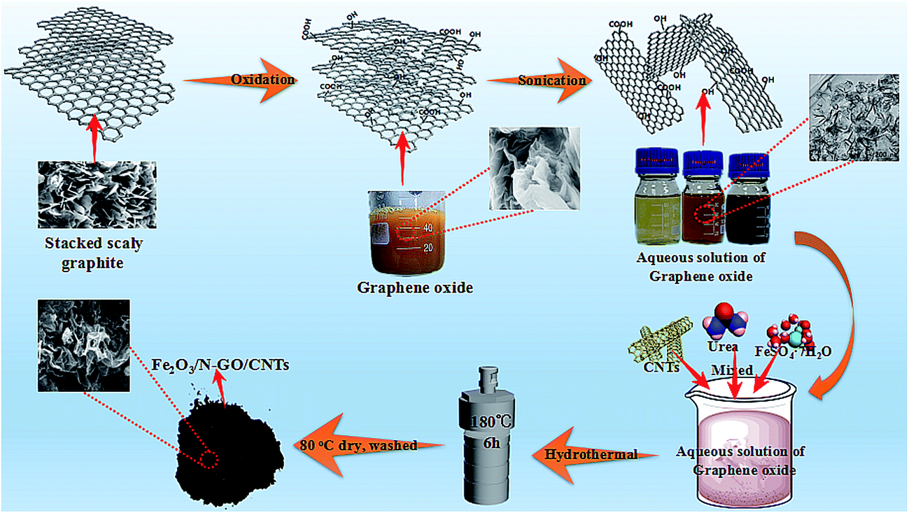 | ||
| Scheme 1 Fabrication process of the magnetic carbonaceous absorbing material. | ||
The crystalline structures of the Fe2O3/GN, Fe2O3/N-GN and Fe2O3/N-GN/CNTs composites were characterized by XRD. As shown in Fig. S1,† the 2θ angles at 24.1°, 33.2°, 35.6°, 40.8°, 54.1°, 62.4° can be assigned to the (012), (104), (110), (113), (116), (214) planes of Fe2O3 (JCPDS no. 33-0664), suggesting that the material should present crystalline Fe2O3 components; this was further supported by the XPS results. Moreover, no obvious characteristic diffraction peaks of GO (at about 10°) or graphite (at about 26°) were detected, which demonstrates the highly disordered distribution of complexes and the low graphitization of hydrothermal reduction products.24 Furthermore, comparing the XRD curves of the Fe2O3/GN and Fe2O3/N-GN samples, it can be clearly seen that the addition of urea did not affect the Fe2O3 crystal formation. The formation mechanism probably occurs due to the relatively low concentration of the precursor in the preparation conditions; moreover, Fe2+ was oxidized to Fe3+ during the high temperature hydrolysis, leading to the in situ formation of Fe2O3 by hydrolysis–dehydration reaction.25 At the same time, for the Fe2O3/N-GN and Fe2O3/N-GN/CNTs samples, the introduction of urea during the preparation process can hydrolyze and release OH− under high temperature conditions, which can also promote the formation of Fe2O3 to a certain extent.
XPS is a very effective technique to investigate the surface states of materials; it can deliver information regarding their atomic compositions and can also identify the types of bonds between atoms. The XPS survey spectra of the Fe2O3/GN, Fe2O3/N-GN and Fe2O3/N-GN/CNTs composites are shown in Fig. 1a. Clearly, four sharp peaks with binding energies at 285, 400, 530 and 711 eV can be observed, which are ascribed to the characteristic peaks of C 1s, N 1s, O 1s and Fe 2p, respectively, demonstrating the existence of C, O, Fe and N elements. When highly accurate XPS spectra were further acquired to elucidate the electronic states of the elements, the Fe2p spectrum of Fe2O3/N-GN/CNTs showed two characteristic peaks at 711 and 725 eV, which were related to Fe 2p3/2 and Fe 2p1/2, respectively. The Fe 2p1/2 and Fe 2p3/2 main peaks are visibly followed by two satellite peaks on their high binding-energy side (at ∼8 eV), as shown in Fig. 1b; these are feature peaks of Fe2O3.26 Moreover, the C 1s spectrum of Fe2O3/N-GN/CNTs shows five peaks, e.g. 284.7, 285.3, 285.7, 286.5 and 289.8 eV, which are attributed to C![[double bond, length as m-dash]](https://www.rsc.org/images/entities/char_e001.gif) C and C–C in aromatic rings, and C–N, C–O and C(O)O groups, respectively (Fig. 1c). These results further confirm that nitrogen atoms have been effectively doped in the graphite layers.27 Furthermore, in Table S1,† we list the atomic compositions of the GN, Fe2O3/N-GN and Fe2O3/N-GN/CNTs composites and the content of C 1s chemical groups obtained by their spectral characteristics. The XPS results show that the total C–C content (sp2 + sp3) is higher for Fe2O3/N-GN/CNTs, and the ratio between sp2 and sp3 C is also higher for Fe2O3/N-GN/CNTs than for Fe2O3/N-GN. This further demonstrates the successful introduction of carbon nanotubes, resulting in an increase in CC (sp2) content. This statement is in agreement with the Raman results (see below). Moreover, on comparison, after the hydrothermal reaction, the N 1s peak was detected simultaneously in the Fe2O3/N-GN and Fe2O3/N-GN/CNTs samples, again indicating that N element was successfully incorporated into the composites. The N 1s spectrum of the Fe2O3/N-GN/CNTs hybrid (Fig. 1d) can also be fitted by three deconvoluted peaks at 398.6, 400.1 and 401.7 eV, corresponding to pyridinic N bonding, pyrrolic N bonding and graphitic N bonding, respectively. It is clear that the pyrrolic N bonding configuration is the dominant N-doping type in the composites. Favorably, this form of N-doping can provide a large amount of space on the surface of the graphite layers, leading to an increased number of defect sites, which may produce polarization relaxation and electronic dipole polarization relaxation. This should be beneficial for the absorption of microwaves.28 In addition, the XPS analysis results indicate that the GO was partially reduced and doped with CNTs and N atoms during the formation of Fe2O3 nanocrystals, leading to the formation of Fe2O3/N-GN/CNTs composite; this was further demonstrated by the FTIR spectra.
C and C–C in aromatic rings, and C–N, C–O and C(O)O groups, respectively (Fig. 1c). These results further confirm that nitrogen atoms have been effectively doped in the graphite layers.27 Furthermore, in Table S1,† we list the atomic compositions of the GN, Fe2O3/N-GN and Fe2O3/N-GN/CNTs composites and the content of C 1s chemical groups obtained by their spectral characteristics. The XPS results show that the total C–C content (sp2 + sp3) is higher for Fe2O3/N-GN/CNTs, and the ratio between sp2 and sp3 C is also higher for Fe2O3/N-GN/CNTs than for Fe2O3/N-GN. This further demonstrates the successful introduction of carbon nanotubes, resulting in an increase in CC (sp2) content. This statement is in agreement with the Raman results (see below). Moreover, on comparison, after the hydrothermal reaction, the N 1s peak was detected simultaneously in the Fe2O3/N-GN and Fe2O3/N-GN/CNTs samples, again indicating that N element was successfully incorporated into the composites. The N 1s spectrum of the Fe2O3/N-GN/CNTs hybrid (Fig. 1d) can also be fitted by three deconvoluted peaks at 398.6, 400.1 and 401.7 eV, corresponding to pyridinic N bonding, pyrrolic N bonding and graphitic N bonding, respectively. It is clear that the pyrrolic N bonding configuration is the dominant N-doping type in the composites. Favorably, this form of N-doping can provide a large amount of space on the surface of the graphite layers, leading to an increased number of defect sites, which may produce polarization relaxation and electronic dipole polarization relaxation. This should be beneficial for the absorption of microwaves.28 In addition, the XPS analysis results indicate that the GO was partially reduced and doped with CNTs and N atoms during the formation of Fe2O3 nanocrystals, leading to the formation of Fe2O3/N-GN/CNTs composite; this was further demonstrated by the FTIR spectra.
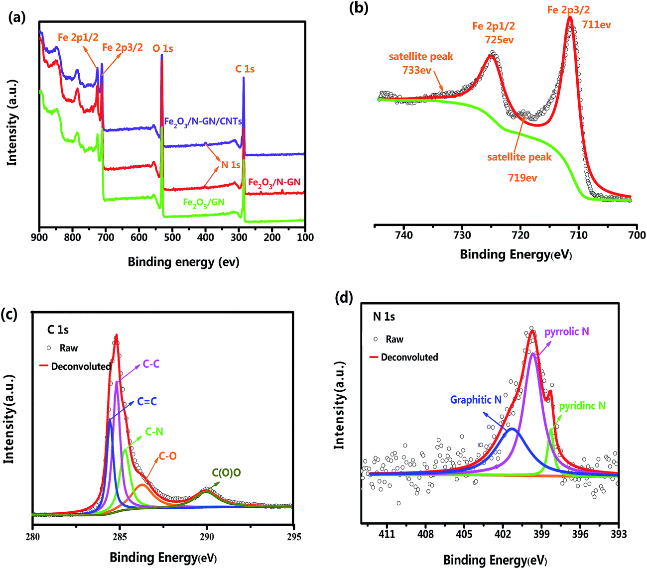 | ||
| Fig. 1 (a) XPS survey spectra of the Fe2O3/GN, Fe2O3/N-GN and Fe2O3/N-GN/CNTs composites. (b) Fe (2p), (c) C (1s) and (d) N (1s) core level spectra of the Fe2O3/N-GN/CNTs composites. | ||
In addition, FTIR spectroscopy can provide information on the bonding of organic functional groups. The FTIR adsorption spectra of the GO, Fe2O3/GN, Fe2O3/N-GN and Fe2O3/N-GN/CNTs composites are displayed in Fig. 2. It can be observed from the FTIR spectrum of GO that a band appearing at about 3440 cm−1 was associated with (O–H) stretching vibrations, indicating that the material still contains a small amount of adsorbed water molecules. In addition, the peaks that appeared at around 2930 and 2921 were ascribed to the stretching frequency of C–H. The band at about 1620 cm−1 was related to stretching vibrations from (CC) and assigned to the skeletal vibrations of unoxidized graphitic domains or contributions from the stretching deformation vibration of intercalated water.29 The bands located at about 1429 and 1057 cm−1 were ascribed to (O–H) symmetric deformation vibrations and (C–O) (epoxy or alkoxy) stretching vibrations, respectively. Moreover, the band for (CO) in carboxylic acid and carbonyl moieties (carbonyl) was observed at around 1743 cm−1.30 By comparing the FTIR spectra of Fe2O3/GN and GO, it can be found that most of the oxygen-containing groups, such as (CO) bonds, (C–OH) bonds and (C–O) bonds, were partly removed during the hydrothermal process, indicating that GO could be reduced to a certain extent under high temperature. However, it can also be observed from the FTIR spectrum of Fe2O3/GN that a band appeared at around 576 cm−1; this was attributed to Fe–O stretching vibrations. Moreover, on comparing the FTIR spectra of Fe2O3/GN, Fe2O3/N-GN and Fe2O3/N-GN/CNTs, it is found that the characteristic peaks appearing in the spectra, such as those at ∼3440, ∼1620 and ∼576 cm−1, are similar. However, there is a small difference in the 1100 to 1600 cm−1 region. The differences in the feature peaks at ∼1545 and ∼1150 cm−1 were ascribed to CN stretching vibrations and C–N stretching vibrations, respectively.31 Therefore, these results show that the addition of urea could simultaneously enable hydrothermal reduction of GO and introduce nitrogen atoms into the final sample.
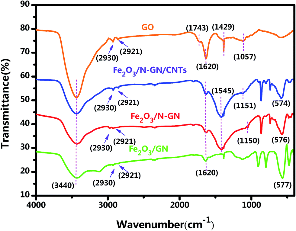 | ||
| Fig. 2 FTIR spectra of the GO, Fe2O3/GN, Fe2O3/N-GN and Fe2O3/N-GN/CNTs composites. | ||
Raman spectroscopy, an efficient and non-multilative technique, can be used to identify the bonding and microstructures of C-species materials. In order to understand the chemical bonds in the carbon skeleton of in the hybrid system and any structural changes, Raman spectroscopy was adopted. Fig. 3 shows two representative Raman spectra of the GO, Fe2O3/GN, Fe2O3/N-GN and Fe2O3/N-GN/CNTs composites. As shown in Fig. 3, the D band at ∼1340 cm−1 and the G band at ∼1590 cm−1 can be clearly detected in the three composites. The G band is a characteristic feature of graphitic layers, while the D band corresponds to disordered carbon.32 The intensity ratio of the D and G bands (ID/IG) is related to the disordered structure of carbon.33 Compared with GO and Fe2O3/GN, Fe2O3/N-GN reveals an obviously enhanced value of ID/IG, indicating that more defects are introduced into the Fe2O3/N-GN composite during the hydrothermal reduction process. This probably originates from the incorporation of N atoms, which may disrupt the sp2 structure of the hexagonal lattice domain, resulting in the formation of sp3 defects and disordered sites; this is helpful to improve the dielectric loss of microwave absorbing materials.34 However, in contrast to Fe2O3/N-GN, the ID/IG ratio of Fe2O3/N-GN/CNTs has a certain degree of decline, which can be associated with the insertion of more structured carbon CNTs in the N-doped graphite layers.35 In addition, we analyzed the variation of the 2D peak at about 2680 cm−1. The number of layers of graphene was calculated using the I2D/IG ratio; the layers increased with increasing I2D/IG ratio. Clearly, the intensity ratio of I2D/IG of the Fe2O3/N-GN/CNTs hybrid is greater than that of Fe2O3/GN and the Fe2O3/N-GN hybrid (Fig. 3). This result indicates that the insertion of CNTs may play an important role in the separation of graphene sheets, leading to the construction of the 3D composite structure.
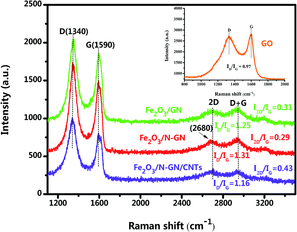 | ||
| Fig. 3 Raman spectra of the GO, Fe2O3/GN, Fe2O3/N-GN and Fe2O3/N-GN/CNTs composites. | ||
The morphologies and microstructures of the synthesized Fe2O3/GN, Fe2O3/N-GN and Fe2O3/N-GN/CNTs composites were investigated by TEM, and the results are presented in Fig. 4. In Fig. 4a, it can be clearly seen that the GO consists of transparent silky nanosheets with some wrinkles on their surfaces. In addition, the GO nanosheets are almost transparent, indicating that they are very thin. Fig. 4b shows the TEM micrograph of Fe2O3/GN, which clearly reveals that their shapes are irregular spheres with diameters from 300 to 500 nm, and the distribution is uneven. As shown in Fig. 4c and d, the GO nanosheets were decorated with large Fe2O3 nanoparticles via a hydrothermal process. Most of the Fe2O3 nanoparticles supported on the N-doped graphene sheets (N-GN) are about 40 to 50 nm, which is much smaller than the Fe2O3 nanoparticles on the graphene sheets (GN), and the fine Fe2O3 nanocrystals are uniformly decorated on the surfaces of the transparent and wrinkled graphene sheets without aggregation. All the Fe2O3 nanoparticles remained firmly attached to the N-GN sheets even after sonication was applied during the preparation of TEM specimens, indicating that strong adhesion between the Fe2O3 nanoparticles and N-GN sheets was obtained. The presence of oxygen-containing functional groups such as carboxyl groups (–COOH) and hydroxyl groups (–OH) on the surface of the GO allows iron ions to be adsorbed onto the surface by electrostatic attraction.36 Moreover, GO interacted with the nitrogen material from urea; thus, N could be doped on the surface of GO, resulting in the formation of defects on the surface of the graphene.37 These doped-N sites can potentially coordinate with iron ions in an Fe–N complex arrangement. This can improve the dispersion of ions and reduce agglomeration, which can indirectly control the size of magnetic particles. Thus, we can conclude that the doping of nitrogen atoms can lead to the formation of defects in the surfaces of the graphene sheets. These defects provide a large number of nucleation sites for the formation of Fe2O3 nanoparticles, thus suppressing the particle size of the Fe2O3 nanoparticles and enabling them to distribute more uniformly on the in situ-assembled N-doped graphene sheets.38 In addition, Fig. 4e shows a lattice image of Fe2O3; an ordered array of crystal lattices with an interplanar spacing of 0.252 nm, belonging to the (110) plane, can be clearly seen, which is further supported by the XRD results given above. Furthermore, in contrast to Fe2O3/N-GN, upon the incorporation of CNTs, the internal structure clearly became more complex. Fig. 4f and g displays the TEM image of the as-prepared Fe2O3/N-GN/CNTs composites. It is worth noting that CNTs with diameters of 20–40 nm are inserted into the N-doped graphene sheets and form a new type of three-dimensional conductive grid. The insertion of CNTs into two-dimensional N-GN sheets not only increased the spacing of the N-GN sheets, but also exposed their surface defects. More significantly, these defects can readily form collapses, unevenness and terraces, which are more conducive to the loss of electromagnetic waves.39
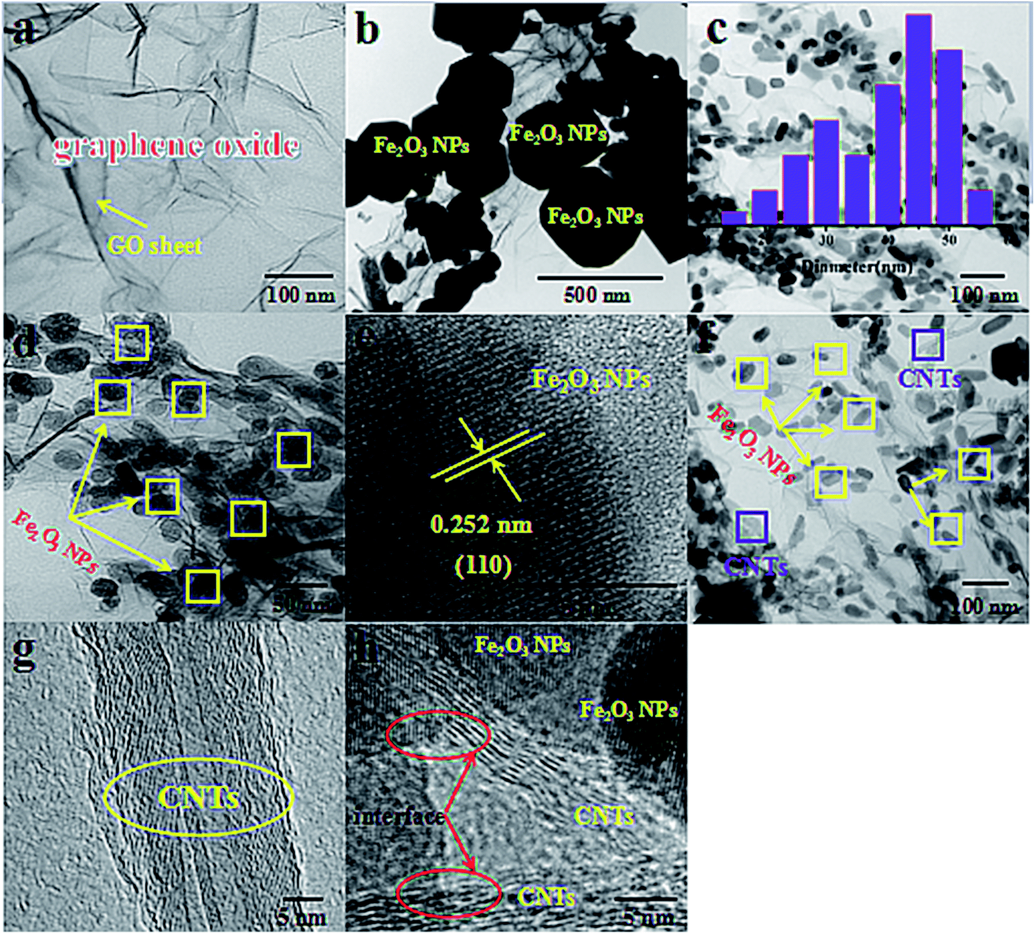 | ||
| Fig. 4 TEM images of (a) GO (150000×), (b) Fe2O3/GN (50000×) and (c) (100000×), (d) Fe2O3/N-GN hybrid (150000×); (e) HRTEM image of the Fe2O3 lattice area of Fe2O3/N-GN (1500000×); TEM and HRTEM images of Fe2O3/N-GN/CNTs: (f) (100000×), (g) (1000000×), (h) (1200000×). | ||
In order to further analyze the intercalation effect of CNTs on N-GN lamellae and the distribution of Fe2O3 nanoparticles in the three-dimensional structure, the Fe2O3/GN, Fe2O3/N-GN and Fe2O3/N-GN/CNTs composite materials were studied by SEM (Fig. 5). As can be seen from Fig. 5a1 and a2, in the absence of doped nitrogen atoms, the Fe2O3 nanoparticles were larger and severely agglomerated. Compared with Fe2O3/GN, after doping with nitrogen atoms, the particle size of Fe2O3 obviously decreased and the distribution became uniform (see insets of Fig. 5b1 and b2). However, as can be seen from Fig. 5b1 and b2, without the addition of CNTs, although the Fe2O3 nanoparticles are evenly distributed on the nitrogen-doped graphene sheet layer, the doping of nitrogen atoms can result in defects and twisting of the two-dimensional graphene plane skeleton. That is, nitrogen atom doping can cause the edges of the nitrogen-doped graphene sheets to curl and overlap with each other, which is not conducive to the formation of electromagnetic wave channels. By comparison, it can also be found that the addition of CNTs can create a large amount of voids on the aggregates, effectively suppressing the overlap between the nitrogen-doped graphene layers (see insets of Fig. 5c1 and c2). As is proposed, when the microwaves pass through the surface of the material, this special heterogeneous interface may cause many electromagnetic waves to diffuse into the material, by which the electromagnetic waves would be effectively weakened.
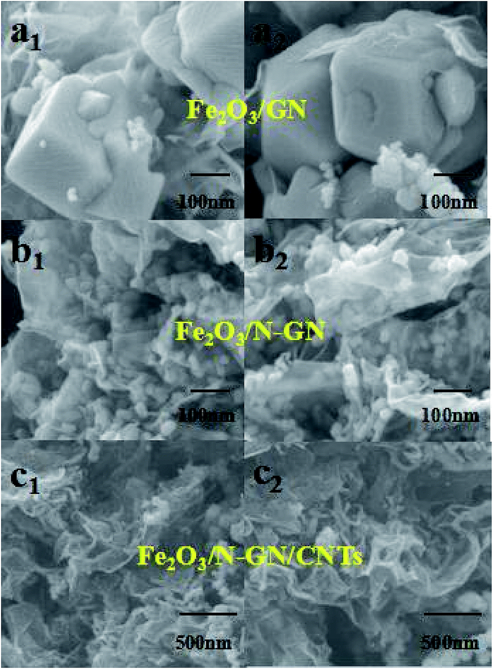 | ||
Fig. 5 SEM images of Fe2O3/GN (a1,2) (50000×), the Fe2O3/N-GN composite (b1,2) (50![[thin space (1/6-em)]](https://www.rsc.org/images/entities/char_2009.gif) 000×) and the Fe2O3/N-GN/CNTs composite (c1,2) (20000×) with different magnifications. 000×) and the Fe2O3/N-GN/CNTs composite (c1,2) (20000×) with different magnifications. | ||
Finally, the specific surface areas of the Fe2O3/N-GN and Fe2O3/N-GN/CNTs composites were examined by nitrogen adsorption–desorption isotherms, as displayed in Fig. S2.† It can be seen that the introduction of CNTs causes the specific surface area and pore volume of Fe2O3/N-GN/CNTs to increase from 23.2 m2 g−1 and 0.17 cm3 g−1 to 45.5 m2 g−1 and 0.28 cm3 g−1, respectively. This indicates that the insertion of CNTs can effectively prevent overlap of the flexible nitrogen-doped graphene sheets. More importantly, a relatively high surface area is favorable for the formation of more diploes, which may cause dipole polarization and improve microwave absorption performance.40
3.2 Magnetic properties
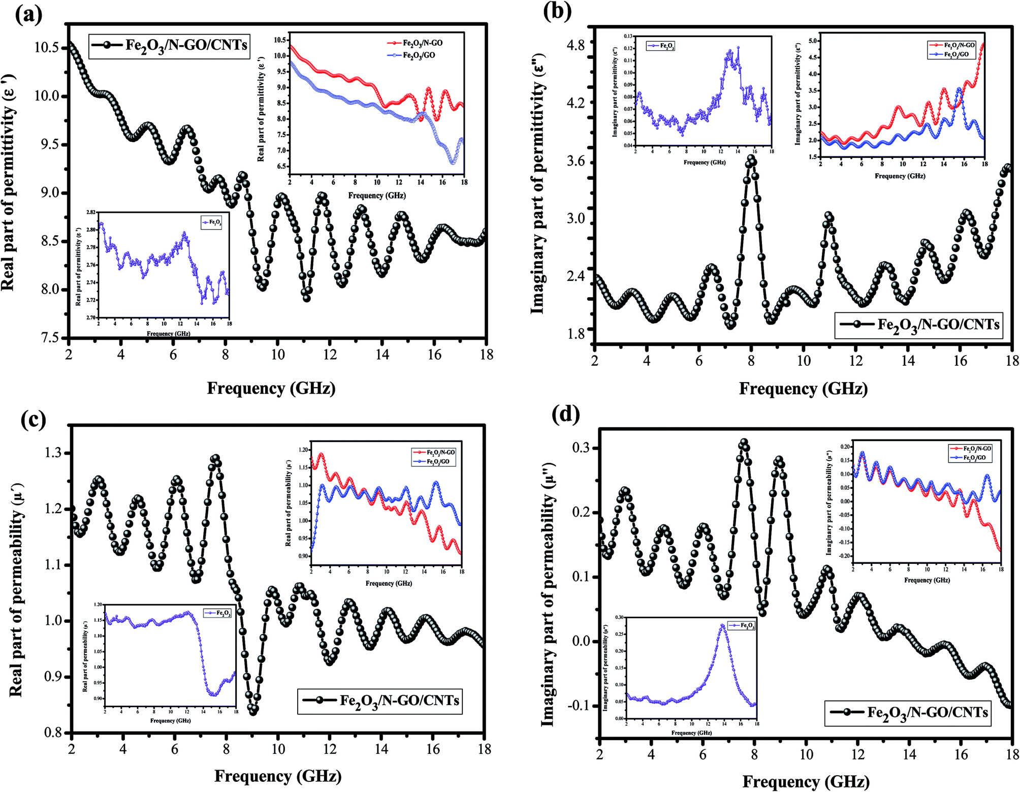
All the above characterization results demonstrated that the 3D Fe2O3/N-GN/CNTs composite was successfully fabricated by a one-step solvothermal process. The 3D layered structure of the prepared Fe2O3/N-GN/CNTs composites is expected to possess excellent electromagnetic wave absorption properties. To start, the magnetic properties of the Fe2O3/N-GN/CNTs and Fe2O3/N-GN composites were studied at room temperature using a vibrating sample magnetometer (VSM). Fig. S3† shows the typical magnetic hysteresis loops of Fe2O3/N-GN/CNTs and Fe2O3/N-GN, which are derived from the presence of magnetic iron oxide particles. The saturation magnetization (Ms), coercivity (Hc), and remnant magnetization (Mr) are 16.467 emu g−1, 146.41 Oe, and 0.56 emu g−1 for Fe2O3/N-GN/CNTs and 19.437 emu g−1, 175.7 Oe, and 3.54 emu g−1 for Fe2O3/N-GN, respectively. It can be clearly seen that the samples show S-like shapes with strong coercivities (Hc) and negligible remnant magnetization (Mr). In addition, the difference in the Ms values of these composites may be attributed to the addition of non-magnetic CNTs.41As is known, for an EM wave absorber, the electromagnetic wave absorption properties and electromagnetic parameters are closely related, i.e. complex permittivity (εr = ε′ − jε′′) and permeability (μr = μ′ − jμ′′). The real parts of the complex permittivity (ε′) and complex permeability (μ′) represent the storage capabilities of the electric and magnetic energies, respectively. In addition, the imaginary parts (ε′′) and (μ′′) are associated with the dissipation energies of electromagnetic energy, respectively.42 Fig. 6 presents the electromagnetic parameters of the composites containing 40% Fe2O3/GN, Fe2O3/N-GN, and Fe2O3/N-GN/CNTs; the EM absorption properties were measured at room temperature in the frequency range of 2 to 18 GHz. As shown in Fig. 6a, for these composites, the ε′ values exhibit a rapid decline in the 2 to 18 GHz frequency range with slight fluctuations. This is due to the higher frequency of the delayed response of the dipole polarization electric field changes.43 The ε′ values decrease gradually from 10.53 at 2 GHz to 8.7 at 18 GHz. Moreover, Fe2O3/N-GN/CNTs reveals the highest ε′ values among the three samples. The higher ε′ values for the Fe2O3/N-GN/CNTs composite are associated with the addition of CNTs. The CNTs may enhance the electric conductivity and electric polarization because εr is a polarizability expression of the absorber. This is also beneficial to improve EM wave absorbing performance.
 | ||
| Fig. 6 Frequency dependence of the (a) real and (b) imaginary parts of the complex permittivity ((ε′) and (ε′′)) and the (c) real and (d) imaginary parts of the complex permeability ((μ′) and (μ′′)) for the samples. | ||
For the ε′′ values (Fig. 6b), all of the samples showed similar trends and nonlinear phenomena. Namely, multiple peaks can be seen in the ε′′ curves; it is worth noting that the ε′′ curves of Fe2O3/N-GN/CNTs exhibit two remarkable resonance peaks in the range of 8 to 11 GHz. This can be ascribed to dipole polarizations arising from dielectric CNTs and interfacial polarization originating from the interface between nitrogen-doped graphite (N-GN) and the CNTs. This suggests that Fe2O3/N-GN/CNTs have a strong dielectric loss against EM waves. In addition, the ε′′ values of Fe2O3/N-GN/CNTs are higher than those of the Fe2O3/GN and Fe2O3/N-GN samples at frequencies under 8.2 GHz. According to free electron theory, ε′′ = σ/2πεof, where σ is the conductivity; it can be found that the conductivity of Fe2O3/N-GN/CNTs is higher at frequencies under 8.2 GHz, resulting in electron loss under electromagnetic radiation.
Debye dipolar relaxation is an important mechanism for dielectric loss. According to the Debye equation, relative complex permittivity εr can be expressed as:44
| εr = ε′ + iε′′ = ε∞ + (εs − εo)/(1 + iωτo) | (1) |
| ε′ = ε∞ + (εs − εo)/[1 + (ωτo)2] | (2) |
| ε′′ = ωτo(εs − εo)/[1 + (ωτo)2] | (3) |
According to eqn (2) and (3), the relationship between ε′ and ε′′ can be deduced as
| [ε′ − (εs + ε∞)/2]2 + (ε′′)2 = [(εs − ε∞)/2]2 | (4) |
| ε′ = ε′′/(2πfτ) + ε∞ | (5) |
We can see that a plot of ε′ versus ε′′ should be a single semicircle, which is defined as a Cole–Cole semicircle. Each semicircle is associated with one Debye relaxation process.45 Fig. 7a–c shows the ε′–ε′′ patterns of the Fe2O3/N-GN/CNTs, Fe2O3/N-GN, and Fe2O3/GN samples. It can be clearly seen from Fig. 7 that the plots of ε′ versus ε′′ for the composites shift to higher values with the addition of nitrogen and the intercalation of the CNTs. These findings suggest an enhanced contribution of Debye relaxation to dielectric loss.46 In addition, as shown in the curve, the Cole–Cole semicircles are contorted, indicating that except for the loss effect that resulted from the Debye relaxation, the cooperative mechanism of Maxwell–Wagner relaxation, conductance loss, dipolar polarization and electron polarization may occur over the resulting composites with inserted CNTs and embedded Fe2O3 NPs.47 Furthermore, the space charge polarization, known as interfacial polarization, often occurs at the heterogeneous interface between two components with different permittivities.48 For the Fe2O3/N-GN/CNTs composites, the multiple phases led to the formation of abundant heterointerfaces between the N-GN, CNTs and Fe2O3 phases, producing strong interfacial polarization relaxation and accounting for the large dielectric loss.
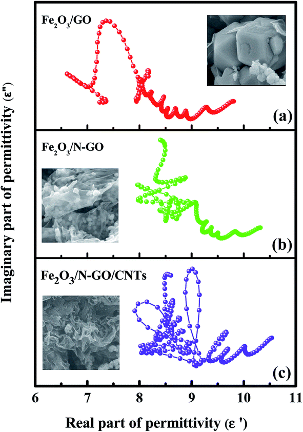 | ||
| Fig. 7 ε′–ε′′ curves of the Fe2O3/GN, Fe2O3/N-GN and Fe2O3/N-GN/CNTs composites. | ||
Fig. 6c and d show the complex permeabilities of the three samples. The complex permeabilities of all the samples reveal decreasing trends with increasing measured frequency in the μ′ curves; this can be attributed to Snoek's limitation in the GHz frequency range,49 particularly for magnetic materials with relatively high conductivities. Therefore, it is not difficult to understand that the μ′ values of Fe2O3/N-GN/CNTs rapidly decrease above 8.1 GHz (Fig. 6c). For μ′′ (Fig. 6d), two obvious resonance peaks can be observed at about 7 to 10 GHz; these are related to natural resonance.50 In general, the magnetic loss mainly arises from hysteresis loss, domain wall resonance, natural resonance, exchange resonance and eddy current effects. The hysteresis loss in the weak field is negligible, and the domain wall resonance is usually located at a much lower range of the MHz frequency; thus, the magnetic loss caused by domain wall resonance and hysteresis loss can be eliminated. If the eddy current dominates the magnetic loss mechanism, the values of Co = μ′′(μ′)−2f−1 should be constant when the frequency varies.51 As shown in Fig. 8, the value of Co decreases rapidly at the lower range of 2 to 10 GHz; this is mainly caused by the natural resonance and exchange resonance. However, when the frequency exceeds 10 GHz, the values of Co = μ′′(μ′)−2f−1 are nearly constant, suggesting that the composites have a significant eddy current effect at the higher range of 10 to 18 GHz. Thus, we can conclude that the contributions to magnetic loss result from natural resonance and that both exchange resonance and eddy current effects are crucial aspects.
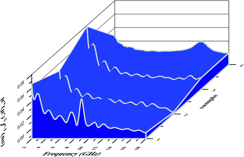 | ||
| Fig. 8 The values of μ′′(μ′)−2f−1 of the Fe2O3/GN, Fe2O3/N-GN and Fe2O3/N-GN/CNTs composites. | ||
As is known, the two possible contributions to electromagnetic wave absorption are dielectric loss and magnetic loss.52 In order to further study which contribution is dominant for the resulting composites, the dielectric loss tangents (tanδe = ε′′/ε′) and magnetic loss tangents (tanδm = μ′′/μ′) of the Fe2O3/N-GN/CNTs, Fe2O3/N-GN, and Fe2O3/GN samples were measured (see Fig. S4†). Throughout the frequency range, the dielectric loss tangent (tanδe = ε′′/ε′) is greater than the magnetic loss tangent (tanδm = μ′′/μ′), which indicates that dielectric loss plays an important role in the EM absorption of these samples. Moreover, assuming that the magnetic loss is nearly equal to the dielectric loss, the absorber will show great microwave absorption.53 From Fig. S4,† it is worth noting that Fe2O3/N-GN/CNTs has similar dielectric and magnetic losses, indicating that these composites may have excellent microwave absorption properties. In order to clarify the impedance matching phenomenon, we used the impedance matching ratio (Zr = Zin/Z0) to explain the degree of impedance matching of the composites.54
|
Zr = |Zin/Z0| = (μr/εr)1/2tanh[j(2πfd)/c(μrεr)1/2]
| (6) |
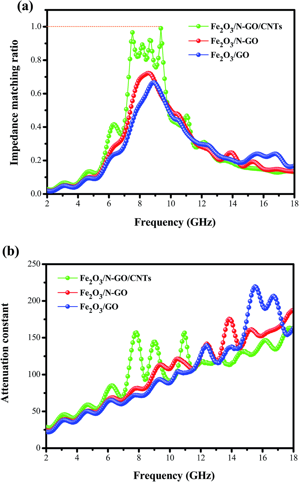 | ||
| Fig. 9 Frequency dependence of the normalized input impedance (a) and attenuation constant (b). | ||
To obtain superior absorbers, in addition to considering good impedance matching, it is also necessary to enable electromagnetic waves to penetrate into the material, increasing the microwave attenuation. The dissipation characteristics of an absorbent material are usually expressed by the attenuation constant, α. Accordingly, we calculated the attenuation constants α of the three composites as follows:55
| α = (√2πf/c) × √[(μ′′ε′′ − μ′ε′) + √[(μ′′ε′′ − μ′ε′)2 + (μ′′ε′′ + μ′ε′)2]] | (7) |
To evaluate the electromagnetic wave absorption properties of the as-synthesized samples, the reflection loss (RL) values can be calculated from the measured relative complex permittivity (εr) and permeability (μr) dates for the given frequency range (2 to 18 GHz) and different absorber thicknesses; according to transmission line theory, the reflection loss RL (dB) can be calculated according to the following equations:56
|
Zin = Z0(μr/εr)1/2tanh[j(2πfd)/c(μrεr)1/2]
| (8) |
|
RL = 20log|(Zin − Z0)/(Zin + Z0)|
| (9) |
| tm = nλ/4 = nc/(4fm√|μr‖εr|) (n = 1, 3, 5…) | (10) |
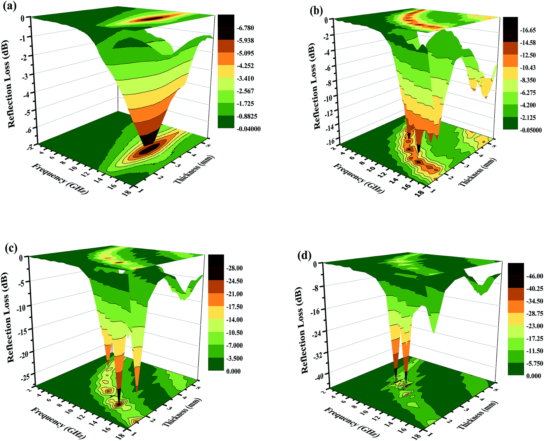 | ||
| Fig. 10 Three-dimensional images of the calculated RL values of the (a) Fe2O3, (b) Fe2O3/GN, (c) Fe2O3/N-GN and (d) Fe2O3/N-GN/CNTs composites. | ||
Based on the above analysis results, one may safely draw the conclusion that good impedance matching and strong attenuation capability are responsible for the superior microwave absorbing properties of the samples. Furthermore, the unique layered structure can enhance the electromagnetic wave absorption performance. Scheme 2 is a schematic of the microwave absorbing mechanism of the Fe2O3/N-GN/CNTs composite. First, the excellent microwave absorption properties are related to the unique 3D layered structure. Nitrogen-doped graphene (N-GN) sheets can act as a microwave receiver. When the electromagnetic waves infiltrate the N-GN sheets, they can be trapped by the inner void space, and the relatively large surface area and high pore volume can result in multiple reflections and diffuse scattering of the incident electromagnetic waves for long periods, converting electromagnetic energy into heat energy or other forms of energy.58 Second, the introduction of magnetic Fe2O3 particles in nitrogen-doped graphene (N-GN) sheets and CNTs can improve the characteristic impendence matching of the composite. Therefore, more EM waves can enter the absorbers and dissipate by the following mechanisms.59 Third, according to the XPS and FTIR spectra, residual oxygen functional groups, such as hydroxyl and carbonyl groups, remain after the hydrothermal reaction; moreover, disordered carbon and defects exist in the nitrogen-doped graphene surfaces. These residual groups and defects act as polarized centers that can introduce defect polarization relaxation and relaxation processes, which all support microwave absorption.60 Therefore, it is proposed that a novel absorption mechanism can be illustrated based on the layered structure; that is, the hierarchical structure provides a container which attenuates electromagnetic energy by extension through the travel path while gradually reducing energy.
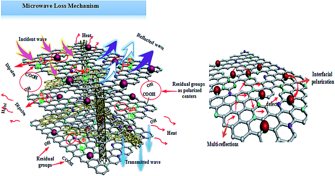 | ||
| Scheme 2 Possible mechanism for the microwave absorption of the Fe2O3/N-GN/CNTs composites. | ||
Generally, these high-performance absorbers are required to have strong absorption, broad effective frequency (fE), thinness and light weight. To evaluate the absorption properties of the Fe2O3/N-GN/CNTs composite, we list the reflection-loss properties of various GN-derived absorbers reported in previous references in Table 1. It was found that both the transition metal materials and the hybrids with GN had strong reflection loss (less than −30 dB), including RGO/SiO2/Fe3O4,11 RGO/α-Fe2O3 (ref. 13) and GO/CNT-Fe3O4.14 Furthermore, the optimal reflection loss and effective bandwidth of Fe2O3/N-GN/CNTs in this work are very competitive with those of previously reported GN-derived composites. For example, compared with RGO/α-Fe2O3 and GO/CNT–Fe3O4, Fe2O3/N-GN/CNTs shows strong microwave absorption ability and broader effective bandwidth, which are attributable to the introduction of nitrogen atoms and CNTs. However, compared with RGO/SiO2/Fe3O4 and S-PPy/RGO, although the electromagnetic wave loss performance of Fe2O3/N-GN/CNTs is reduced, the effective bandwidth and the matching thickness of Fe2O3/N-GN/CNTs are even better than those of RGO/SiO2/Fe3O4 and S-PPy/RGO. In addition, further comparisons revealed that the optimized GN-derived absorber obtained in this experiment has very strong absorption characteristics, very low thickness and wide absorption frequency ranges. In view of these advantages, the newly fabricated Fe2O3/N-GN/CNTs composite material can be considered to be a new high-performance electromagnetic wave absorber with great potential.
| Sample | RL (dB) | Thickness (mm) | Frequency range (GHz) | Ref. |
|---|---|---|---|---|
| RGO/SiO2/Fe3O4 | −56.4 | 4.5 | 3.5 | 11 |
| S-PPy/RGO | −54.4 | 5.0 | 3.32 | 12 |
| RGO/α-Fe2O3 | −38 | 2.0 | 5.8 | 13 |
| GO/CNT–Fe3O4 | −37 | 5.0 | 2.1 | 14 |
| CNT/RGO/BaFe12O19 | −19.03 | 2.5 | 3.8 | 61 |
| 3D GNs/INAW | −12.81 | 2.0 | 2.1 | 62 |
| Ni–graphene | −13 | 2.0 | 2.6 | 63 |
| Fe3O4–graphene | −26.4 | 4.0 | 2.0 | 64 |
| GN–polyaniline | −36.9 | 3.5 | 5.3 | 65 |
| Fe2O3/N-GN/CNTs | −45.8 | 3.0 | 3.7 | This work |
4. Conclusions
In summary, a new 3D Fe2O3/N-GN/CNTs composite with significantly enhanced comprehensive MA properties has been successfully synthesized via a facile in situ solvothermal method. Due to nitrogen doping into graphene nano-sheets, the Fe2O3 particles can be well dispersed within the composite structure without distinct aggregation; moreover, CNTs were successfully inserted into the two-dimensional lamellae of N-doped graphene to form a continuous conductive network and fully expose the lattice defects on the N-GN surface, which provides a large number of nucleation sites for Fe2O3 crystal growth in situ. When evaluated as a MA material, Fe2O3/N-GN/CNTs exhibited excellent MA properties in terms of maximum RL value, broad bandwidth, light weight and low thickness. The maximum RL of −45.8 dB can be achieved at 9.32 GHz with a matching thickness of only 3 mm. The effective absorption (below −10 dB) bandwidth reaches 14.5 GHz (3.5 to 18.0 GHz). These excellent MA properties can be mainly associated with the good impedance matching, strong loss characteristics, interfacial polarization and polarization relaxation of the material. Overall, it is believed that this newly designed Fe2O3/N-GN/CNTs composite with enriched interfaces and a controllable hierarchical structure will be a high-performance MA absorbing candidate for practical applications.Conflicts of interest
There are no conflicts to declare.Acknowledgements
Financial support from the National Natural Science Foundation of China (21546008, 21676039) and the Opening Foundation of State Key Laboratory of Inorganic Synthesis and Preparative Chemistry of Jilin University (2016-04) are kindly acknowledged.References
- V. K. Tyagi and S. L. Lo, Renewable Sustainable Energy Rev., 2013, 18, 288–305 CrossRef CAS.
- R. Kumaran, K. S. Dinesh, N. Balasubramanian, M. Alagar, V. Subramanian and K. Dinakaran, J. Phys. Chem. C, 2016, 120, 13771–13778 CAS.
- P. Saini, M. Arora, G. Gupta, B. K. Gupta, V. N. Singh and V. Choudhary, Nanoscale, 2013, 5, 4330–4336 RSC.
- K. Jia, R. Zhao, J. C. Zhong and X. B. Liu, J. Magn. Magn. Mater., 2010, 322, 2167–2171 CrossRef CAS.
- S. B. Ni, X. L. Sun, X. H. Wang, G. Zhou, F. Yang, J. M. Wang and D. Y. He, Mater. Chem. Phys., 2010, 124, 353–358 CrossRef CAS.
- F. L. Wang, J. R. Liu, J. Kong, Z. J. Zhang, X. Z. Wang, M. Itoh and K. Machida, J. Mater. Chem., 2011, 21, 4314–4320 RSC.
- Y. Zhang, Y. Huang, T. F. Zhang, H. C. Chang, P. S. Xiao and Y. S. Chen, Adv. Mater., 2015, 27, 2049–2053 CrossRef CAS PubMed.
- Y. Zhang, Y. Huang, H. H. Chen, Z. Y. Huang, Y. Yang and Y. S. Chen, Carbon, 2016, 105, 438–447 CrossRef CAS.
- J. J. Liang, Y. Wang, Y. Huang, Y. F. Ma, Z. F. Liu and J. M. Cai, Carbon, 2009, 47, 922–925 CrossRef CAS.
- K. Singh, A. Ohlan, V. H. Pham, S. Varshney, J. Jang and J. S. Chung, Nanoscale, 2013, 5, 2411–2420 RSC.
- Y. J. Xu, Q. Wang, Y. F. Cao, X. F. Wei and B. Q. Huang, RSC Adv., 2017, 7, 18172–18177 RSC.
- F. Wu, A. M. Xie, M. X. Sun, Y. Wang and M. Y. Wang, J. Mater. Chem. A, 2015, 3, 14358–14369 CAS.
- T. H. Wang, Y. F. Li, L. Wang, C. Liu, S. Geng, X. L. Jia, F. Yang, L. Q. Zhang, L. P. Liu, B. You, X. Ren and H. T. Yang, RSC Adv., 2015, 5, 60114–60120 RSC.
- L. N. Wang, X. L. Jia, Y. F. Li, F. Yang, L. Q. Zhang, L. P. Liu, X. Ren and H. T. Yang, J. Mater. Chem. A, 2014, 2, 14940–14946 CAS.
- M. Mishra, A. P. Singh, B. P. Singh, V. N. Singh and S. K. Dhawan, J. Mater. Chem. A, 2014, 2, 13159–13168 CAS.
- Z. S. Wu, W. C. Ren and L. Xu, ACS Nano, 2011, 5, 5463–5471 CrossRef CAS PubMed.
- L. F. Shen, X. G. Zhang and S. H. Li, J. Phys. Chem. Lett., 2011, 2, 3096–3101 CrossRef CAS.
- M. Beidaghi and C. L. Wang, Adv. Funct. Mater., 2012, 22, 4501–4510 CrossRef CAS.
- J. L. Lv, S. R. Zhai, C. Gao, N. Zhou, Q. D. An and B. Zhai, Chem. Eng. J., 2016, 289, 261–269 CrossRef CAS.
- N. Zhou, Q. D. An, W. Zheng, Z. Y. Xiao and S. R. Zhai, RSC Adv., 2016, 6, 98128–98140 RSC.
- N. Zhou, Q. D. An, Z. Y. Xiao, S. R. Zhai and Z. Zhan, ACS Sustainable Chem. Eng., 2017, 5, 5394–5407 CrossRef CAS.
- W. S. Hummers and R. E. Offeman, J. Am. Chem. Soc., 1958, 80, 1339 CrossRef CAS.
- Z. X. Li, X. H. Li, Y. Zong, G. G. Tan, Y. Sun, Y. Y. Lan, M. He, Z. Y. Ren and X. L. Zheng, Carbon, 2017, 115, 493–502 CrossRef CAS.
- D. W. Wang, Y. Q. Li and Q. H. Wang, J. Solid State Electrochem., 2012, 16, 2095–2102 CrossRef CAS.
- B. Wang, J. S. Chen and X. W. Lou, J. Am. Chem. Soc., 2011, 133, 4940–4947 CrossRef PubMed.
- A. Nasibulin, S. Rackauskas, H. Jiang, Y. Tian, P. Mudimela, S. Shandakov, L. Nasibulina, S. Jani and E. Kauppinen, Nano Res., 2009, 2, 373–379 CrossRef CAS.
- P. Su, H. L. Guo and S. Peng, Acta Phys.–Chim. Sin., 2012, 28, 1–9 Search PubMed.
- J. Feng, F. Z. Pu, Z. X. Li, X. H. Li, X. Y. Hu and J. T. Bai, Carbon, 2016, 104, 214–225 CrossRef CAS.
- H. K. Jeong, Y. P. Lee, R. J. Lahaye, M. H. Park, K. H. An, I. J. Kim, C. W. Yang, C. Y. Park, R. S. Ruoff and Y. H. Lee, J. Am. Chem. Soc., 2008, 130, 1362–1366 CrossRef CAS PubMed.
- H. L. Guo, X. F. Wang, Q. Y. Qian, F. B. Wang and X. H. Xia, ACS Nano, 2009, 9, 2653–2659 CrossRef PubMed.
- X. L. Zheng, J. Feng, Y. Zong, H. Miao, X. Y. Hu, J. T. Bai and X. H. Li, J. Mater. Chem. C, 2015, 3, 4452–4463 RSC.
- J. J. Tang, J. Yang, X. Y. Zhou, H. M. Yao and L. M. Zhou, J. Mater. Chem. A, 2015, 3, 23844–23851 CAS.
- M. Chen, X. W. Yin, M. Li, L. Q. Chen, L. F. Cheng and L. T. Zhang, Ceram. Int., 2015, 41, 2467–2475 CrossRef CAS.
- X. H. Li, J. Feng, H. Zhu, C. H. Qu, J. T. Bai and X. L. Zheng, RSC Adv., 2014, 4, 33619–33625 RSC.
- Y. Bo, L. L. Wang and L. Yao, ChemComm, 2013, 49, 5016–5018 RSC.
- Y. Nabae, S. Moriya, K. Matsubayashi, S. M. Lyth, M. Malon, L. B. Wu, N. M. Islam and Y. Koshigoe, Carbon, 2010, 48, 2613–2624 CrossRef CAS.
- Z. Y. Lin, G. Waller, Y. Liu, M. L. Liu and C. P. Wong, Adv. Energy Mater., 2012, 2, 884–888 CrossRef CAS.
- M. Du, C. H. Xu and J. Sun, Electrochim. Acta, 2012, 80, 302–307 CrossRef CAS.
- X. F. Zhnag, P. F. Guan and X. L. Dong, Appl. Phys. Lett., 2010, 96, 223111 CrossRef.
- T. S. Wang, Z. L. Liu, M. M. Lu, B. Wen, Q. Y. Ouyang and M. S. Cao, J. Appl. Phys., 2013, 113, 024314–024321 CrossRef.
- X. H. Li, J. Feng, H. Zhu, C. H. Qu, J. T. Bai and X. L. Zheng, RSC Adv., 2014, 4, 33619 RSC.
- R. Qiang, Y. C. Du, H. T. Zhao, Y. Wang, C. H. Tian, Z. G. Li, X. J. Han and P. Xu, J. Mater. Chem. A, 2015, 3, 13426–13434 CAS.
- H. Wang, Y. Y. Dai, D. Y. Geng, S. Ma, D. Li, J. An, J. He, W. Liu and Z. D. Zhang, Nanoscale, 2015, 7, 17312–17319 RSC.
- S. He, G.-S. Wang, C. Lu, J. Liu, B. Wen, H. Liu, L. Guo and M.-S. Cao, J. Mater. Chem. A, 2013, 1, 4685–4692 CAS.
- P. H. Fang, J. Chem. Phys., 1965, 42, 3411–3413 CrossRef CAS.
- T. Wu, Y. Liu, X. Zeng, T. T. Cui, Y. T. Zhao, Y. N. Li and G. X. Tong, ACS Appl. Mater. Interfaces, 2016, 8, 7370–7380 CAS.
- X.-M. Meng, X.-J. Zhang, C. Lu, Y.-F. Pan and G.-S. Wang, J. Mater. Chem. A, 2014, 2, 18725–18730 CAS.
- D. Chuai, X. F. Liu, R. H. Yu, J. R. Ye and Y. Q. Shi, Composites, Part A, 2016, 89, 33–39 CrossRef CAS.
- J. Snoek, Physica, 1948, 14, 207–217 CrossRef CAS.
- B. Zhao, G. Shao, B. Fan, W. Guo, Y. Chen and R. Zhang, Appl. Surf. Sci., 2015, 332, 112–120 CrossRef CAS.
- C. Chen, Q. Liu, H. Bi, W. You, W. She and R. Che, Phys. Chem. Chem. Phys., 2016, 18, 26712–26718 RSC.
- X. G. Liu, Z. Q. Qu, D. Y. Geng, Z. Han, J. J. Jiang, W. Liu and Z. D. Zhang, Carbon, 2010, 48, 891–897 CrossRef CAS.
- H. Lv, G. Ji, W. Liu, H. Zhang and Y. Du, J. Mater. Chem. C, 2015, 3, 10232–10241 RSC.
- H. Lv, H. Zhang, J. Zhao, G. Ji and Y. Du, Nano Res., 2016, 9, 1813–1822 CrossRef CAS.
- X. M. Zhang, G. B. Ji, W. Liu, B. Quan, X. H. Liang, C. M. Shang, Y. Cheng and Y. W. Du, Nanoscale, 2015, 7, 12932–12942 RSC.
- G. Z. Wang, Z. Gao, S. W. Tang, C. Q. Chen, F. F. Duan, S. C. Zhao, S. W. Lin, Y. H. Feng, L. Zhou and Q. Y. Qin, ACS Nano, 2012, 6, 11009 CrossRef CAS PubMed.
- X. M. Zhang, G. B. Ji, W. Liu, X. X. Zhang, Q. W. Gao, Y. C. Li and Y. W. Du, J. Mater. Chem. C, 2016, 4, 1860–1870 RSC.
- L. N. Wang, X. L. Jia, Y. F. Li, F. Yang, L. Q. Zhang, L. P. Liu, X. Ren and H. T. Yang, J. Mater. Chem. A, 2014, 2, 14940–14946 CAS.
- Y. C. Yin, X. F. Liu, X. J. Wei, R. H. Yu and J. L. Shui, ACS Appl. Mater. Interfaces, 2016, 8, 34686–34698 CAS.
- H. L. Xing, Z. F. Liu, L. Lin, L. Wang, D. X. Tan, Y. Gan, X. L. Ji and G. C. Xu, RSC Adv., 2016, 6, 41656–41664 RSC.
- T. K. Zhao, X. G. Ji, W. B. Jin, C. Wang, W. X. Ma, J. J. Gao, A. L. Dang, T. Li, S. M. Shang and Z. F. Zhou, RSC Adv., 2017, 7, 15903–15910 RSC.
- T. K. Zhao, W. B. Jin, X. L. Ji, J. J. Gao, C. Y. Xiong, A. L. Dang, H. Li, S. M. Shang and Z. F. Zhou, RSC Adv., 2017, 7, 16196–16203 RSC.
- Y. Cao, Q. Su, R. Che, G. Du and B. Xu, Synth. Met., 2012, 162, 968–973 CrossRef CAS.
- X. Sun, J. He, G. Li, J. Tang, T. Wang, Y. Guo and H. Xue, J. Mater. Chem. C, 2013, 1, 765–777 RSC.
- X. Chen, F. Meng, Z. Zhou, X. Tian, L. Shan, S. Zhu, X. Xu, M. Jiang, L. Wang, D. Hui, Y. Wang, J. Lu and J. Gou, Nanoscale, 2014, 6, 8140–8148 RSC.
Footnote |
| † Electronic supplementary information (ESI) available. See DOI: 10.1039/c7ra06751h |
| This journal is © The Royal Society of Chemistry 2017 |