 Open Access Article
Creative Commons Attribution 3.0 Unported Licence
Three dimensional Ni1+xFe2−xS4-graphene-2D-MoSe2 as an efficient material for supercapacitors†
Xiao-Feng Tang a,
Zhen-Guo Yang*a and
Jia-Hui Liangb
aDepartment of Materials Science, Fudan University, Shanghai, 200433, P. R. China. E-mail: zgyang@fudan.edu.cn; Fax: +86-021-65642523; Tel: +86-021-65642523
bCollege of Materials Science and Engineering, Donghua University, Shanghai 201620, P. R. China
First published on 22nd September 2017
Abstract
A ternary Ni1+xFe2−xS4-graphene-2D-MoSe2 (Ni1+xFe2−xS4-g-MoSe2) nanocomposite was designed and fabricated through a facile two-step method. Well-dispersed Ni1+xFe2−xS4 nanoparticles on graphene sheets were achieved using a hydrothermal method followed by coating with MoSe2 nanosheets using in situ adsorption. The synergistic effect of the three components present in Ni1+xFe2−xS4-g-MoSe2 yielded enhanced electrochemical properties in terms of high specific capacitance reaching up to 2108 F g−1 at a current density of 1 A g−1, with capacity retention of 93.3% after 4000 cycles at the high charge–discharge current density of 5 A g−1. These outstanding capacitance features were mainly attributed to the unique Ni1+xFe2−xS4-g-MoSe2 nanostructure, allowing easy access to the pseudocapacitive species and fast ion/electron transfer. Overall, the prepared 3D nanocomposite is promising as an electrode material for advanced supercapacitors.
1. Introduction
In the past few years, the increasing demand for large-scale industrial operations has created a new direction focusing on high power and energy-density storage devices.1–6 Among them, supercapacitors (SCs) have attracted particular attention due to their large power densities, long cycle life (>100![[thin space (1/6-em)]](https://www.rsc.org/images/entities/char_2009.gif) 000 cycles), and rapid charge–discharge rates.7–12 It is widely accepted that the key to developing effective SCs relies on the design and synthesis of high-performance electrode materials.13–16 Generally, SCs can be divided into two groups based on their energy storage mechanisms: (i) electrical double-layer capacitors (EDLCs) based on carbon-active materials as electrodes,17–19 and (ii) pseudocapacitors consisting mainly of redox-active materials.20–24
000 cycles), and rapid charge–discharge rates.7–12 It is widely accepted that the key to developing effective SCs relies on the design and synthesis of high-performance electrode materials.13–16 Generally, SCs can be divided into two groups based on their energy storage mechanisms: (i) electrical double-layer capacitors (EDLCs) based on carbon-active materials as electrodes,17–19 and (ii) pseudocapacitors consisting mainly of redox-active materials.20–24
To date, numerous carbonaceous materials, including activated carbon, mesoporous carbon, carbon nanotubes and graphene have been investigated for EDLC electrodes.25–27 However, although carbon-based capacitors provide higher power densities, their energy densities are lower than those of pseudocapacitors. On the other hand, pseudocapacitors suffer from inferior cycling abilities while they possess much higher energy densities.28–31 To reconcile the disadvantages of each SC type, one strategy is to combine both electrode materials by coupling pseudocapacitors with EDLCs based carbon materials.27,32–35
More recent research investigations have been focusing on ternary composites because of their enhanced electrochemical performances when compared to binary composites.26,36–38 The combination between properties of individual components often boosts the performance of the electrodes. However, unfortunately, the pseudocapacitive performance of the hybrid materials is still lacklustre. They lack well-defined nanostructures and inadequate synergistic effects. Thus, a pivotal challenge in energy storage devices is to construct integrated nanoarchitecture of hybrid materials with excellent synergistic effects, where the structural features and electroactivities of each constituent could fully manifest with rapid ion/electron transport.39–45
Two-dimensional (2D) materials, such as molybdenum selenide (MoSe2), are considered as active components for energy devices because of their unique nanosheet morphology and large surface area.46–48 However, using MoSe2 only still suffer from poor electrochemical properties. A feasible way to overcome this issue is by combining MoSe2 with conductive matrices, like graphene and pseudocapacitors to improve the specific capacitance and rate capability of the resulting electrodes. Despite the great efforts devoted in this field, the resulting MoSe2 nanosheets still suffer from agglomerations and separation from the graphene sheets due to the poor interfacial properties. By contrast, ternary co-metal sulfide, such as NiCo2S4, could result in better SCs properties because of its rich redox reactions than binary nickel sulfide and cobalt sulfide.29,31
In this study, the design and fabrication of unique three-dimensional (3D) Ni1+xFe2−xS4-graphene-2D-MoSe2 (Ni1+xFe2−xS4-g-MoSe2) hybrid was performed through a two-step hydrothermal method followed by adsorption. The morphology, microstructure and electrochemical properties of the obtained Ni1+xFe2−xS4-g-MoSe2 in comparison with separate components were investigated. The contributions of the different components in the electrochemical performances were also discussed. Compared to Ni1+xFe2−xS4-g and Ni1+xFe2−xS4-MoSe2 counterparts, the fabricated Ni1+xFe2−xS4-g-MoSe2 exhibited remarkable electrochemical performances with higher capacitance values and long cycle life.
2. Experimental
2.1 Materials and synthesis
Graphite and MoSe2 (99.9%) were purchased from Sigma-Aldrich. All the other chemicals were of analytical grade and used as-received without further purification. Double distilled water was used for the preparation of the aqueous solutions and washing processes.2.2 Preparation of Ni1+xFe2−xS4-g-MoSe2 nanocomposite
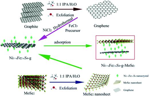
The following procedure was used for the synthesis of the Ni1+xFe2−xS4-g-MoSe2 nanocomposite. Firstly, graphene and MoSe2 nanosheets were prepared according to our previously published report using an initial concentration of 3 mg mL−1.49 Next, Ni (NO3)2·6H2O (1 mmol), FeCl3·6H2O (2 mmol) and thiourea (9 mmol) were dissolved in 25 mL of graphene solution (IPA/water 1![[thin space (1/6-em)]](https://www.rsc.org/images/entities/char_2009.gif) :
:![[thin space (1/6-em)]](https://www.rsc.org/images/entities/char_2009.gif) 1). Ammonia (1 mL) was then added dropwise to the solution followed by magnetic stirring for 0.5 h and sonication for 1 h. The mixture was transferred into a Teflon-lined autoclave, then sealed and heated at 200 °C in an oven for 24 h. The obtained product was filtered off and the collected solid was washed three times with water and ethanol and dried in a vacuum oven at 60 °C for 12 h to yield Ni1+xFe2−xS4-g, which was placed in 25 mL MoSe2 nanosheet solution (IPA/water 1
1). Ammonia (1 mL) was then added dropwise to the solution followed by magnetic stirring for 0.5 h and sonication for 1 h. The mixture was transferred into a Teflon-lined autoclave, then sealed and heated at 200 °C in an oven for 24 h. The obtained product was filtered off and the collected solid was washed three times with water and ethanol and dried in a vacuum oven at 60 °C for 12 h to yield Ni1+xFe2−xS4-g, which was placed in 25 mL MoSe2 nanosheet solution (IPA/water 1![[thin space (1/6-em)]](https://www.rsc.org/images/entities/char_2009.gif) :
:![[thin space (1/6-em)]](https://www.rsc.org/images/entities/char_2009.gif) 1) under sonication for 30 min. Finally, the mixture was left to rest for 24 h, and the resulting Ni1+xFe2−xS4-g-MoSe2 nanocomposite was filtered off and dried in a vacuum. For comparison, the Ni1+xFe2−xS4-MoSe2 counterpart was obtained by the same procedure but without adding the graphene solution. The synthesis process is shown in Fig. 1.
1) under sonication for 30 min. Finally, the mixture was left to rest for 24 h, and the resulting Ni1+xFe2−xS4-g-MoSe2 nanocomposite was filtered off and dried in a vacuum. For comparison, the Ni1+xFe2−xS4-MoSe2 counterpart was obtained by the same procedure but without adding the graphene solution. The synthesis process is shown in Fig. 1.
The working electrodes were prepared by mixing 80 wt% active material, 10 wt% polyvinylidene fluoride (PVDF) and 10 wt% carbon black. The mixture was then dispersed in N-methyl-2-pyrrolidone to form a homogeneous slurry. After that, the slurry was pasted on nickel foams and pressed into thin disk electrodes with uniform thicknesses (10 MPa for 1 min). The mass loading of the active materials on each electrode was approximately 4 mg cm−2.
2.3 Characterization
The X-ray diffraction (XRD) patterns were recorded on a Rigaku D/MaxUltima II Powder XRD 6s X-ray diffractometer, operating at 40 kV and 20 mA using Cu K radiation (λ = 0.15406 nm). Fourier transformation infrared profiles (FTIR) were measured on a Nicolet 670 spectrometer using KBr pellets. UV-Vis diffusive reflectance spectra were acquired on a Shimadzu UV-3600 spectrophotometer. Raman was conducted using a 514 nm wavelength laser on a RENISHAW invia Raman Microscope. Thermogravimetric analysis (TGA) was conducted on a TA Q-600 from ambient temperature to 600 °C in argon atmosphere at a heating rate of 10 °C min−1. The elemental compositions were determined using XPS (PHI Quantera X-ray photoelectron spectrometer). The morphologies of the nanocomposites were obtained by field emission scanning electron microscopy (FEI Quanta 400 ESEM FEG), transmission electron microscopy (TEM), and high-resolution TEM (HRTEM) acquired with a JEOL 2010 at the acceleration voltage of 200 kV. Nitrogen adsorption–desorption isotherms were carried out on Micromeritics Tristar 3000 porosimeter at 77 K.An Autolab 302 electrochemical workstation was used to characterize the electrochemical behaviors. A three-electrode glass cell containing 6 M KOH aqueous electrolyte was employed for the electrochemical measurements. The cyclic voltammetry (CV) curves were obtained at various scan rates (5, 10, 20, 50, and 100 mV s−1) in the potential window of 0–0.6 V. The galvanostatic charge–discharge (GCD) was recorded at various current densities (1, 2, 5, 10 and 20 A g−1) in the potential window of 0–0.4 V.
3. Results and discussion
3.1 Characterization
Fig. 2a shows the XRD patterns of the as-prepared samples. Except the few peaks indexed to MoSe2, all the other features could be ascribed to the cubic phase of Ni1+xFe2−xS4 (JCPDS no. 47-1740). The shift of the (002) peak to lower 2θ values when compared to bulk MoSe2 suggested an expanded layer space in MoSe2, resulting from the liquid phase exfoliation (LPE).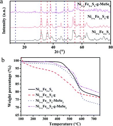 | ||
| Fig. 2 XRD patterns (a) and TGA curves (b) of Ni1+xFe2−xS4, Ni1+xFe2−xS4-g, Ni1+xFe2−xS4-MoSe2, and Ni1+xFe2−xS4-g-MoSe2. | ||
Fig. 2b illustrates the TGA curves of Ni1+xFe2−xS4, Ni1+xFe2−xS4-g, Ni1+xFe2−xS4-MoSe2, and Ni1+xFe2−xS4-g-MoSe2. A weight loss of Ni1+xFe2−xS4 occurred in the 400–600 °C range (Fig. 2b), attributed to the thermal decomposition of Ni1+xFe2−xS4. The TGA profiles indicated that the addition of graphene and MoSe2 nanosheets improved the thermal stability of the nanocomposites.
The Raman spectra of the samples are depicted in Fig. S1.† The spectra consisted of sharp peaks between 200 and 600 cm−1, typically associated with the crystalline Ni1+xFe2−xS4 and MoSe2. The peaks were overlapped with each other, making them hard to distinguish. D and G peaks of graphene were visible around 1300–1600 cm−1.
The FTIR spectra of Ni1+xFe2−xS4, Ni1+xFe2−xS4-g, Ni1+xFe2−xS4-MoSe2 and Ni1+xFe2−xS4-g-MoSe2 are gathered in Fig. S2.† Typical peaks of Ni1+xFe2−xS4 and MoSe2 can be seen around 600 and 1100 cm−1 while the characteristic skeletal vibration of C![[double bond, length as m-dash]](https://www.rsc.org/images/entities/char_e001.gif) C in graphene nanosheets appeared at 1625 cm−1. This confirmed the formation of the sp2 carbon skeleton.
C in graphene nanosheets appeared at 1625 cm−1. This confirmed the formation of the sp2 carbon skeleton.
To gain further information on the chemical state of Ni1+xFe2−xS4 in Ni1+xFe2−xS4-g-MoSe2, X-ray photoelectron spectroscopy (XPS) was conducted and the results are shown in Fig. S3.† The XPS survey spectrum of Ni1+xFe2−xS4-g-MoSe2 indicated the presence of C, Ni, Fe, Mo and Se elements (Fig. S3a†). As shown in Fig. S3b,† the binding energies of Fe 2p3/2 and Fe 2p1/2 were recorded at 711.4 and 724.9 eV, respectively. Similarly, the Ni 2p spectrum (Fig. S3c†) can be fitted by two spin–orbit doublets, characteristic of Ni2+ and Ni3+ with two shake-up satellites. The Mo 3d (Fig. S3d†) and Se 2p spectra (Fig. S3e†) can also be divided into two main peaks.
Overall, XRD, TGA, FTIR, Raman and XPS analysis showed that the ternary Ni1+xFe2−xS4-g-MoSe2 nanocomposite and its counterparts were successfully prepared.
SEM and TEM were conducted to analyze the morphology of the samples. Ni1+xFe2−xS4-g-MoSe2 exhibited typical clusters of nanosheets (Fig. 3a). The high magnification image shown in Fig. 3b revealed that Ni1+xFe2−xS4, graphene and MoSe2 nanosheets were interconnected. The TEM of Ni1+xFe2−xS4-g-MoSe2 further indicated that the Ni1+xFe2−xS4 sheets were composed of nanoparticles with average diameters of about 20 nm lying on graphene and MoSe2 sheets (Fig. 3c). The microstructure of Ni1+xFe2−xS4-g-MoSe2 was further investigated by HRTEM, and the data are illustrated in Fig. 3d. The lattice fringes could be assigned to the following crystal planes: 0.34 nm for graphene (002) and 0.28 nm for MoSe2 (002). Moreover, from the electron diffraction pattern, it could be found that mixed pattern of crystals exist. The collected indices were consistent with the XRD data, demonstrating the successful formation of sheet-particle-sheet structure.
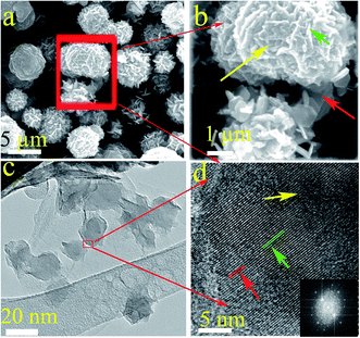 | ||
| Fig. 3 Low and high-resolution SEM (a and b) and TEM images (c and d) of Ni1+xFe2−xS4-g-MoSe2. Inset is the corresponding electron diffraction pattern. | ||
Based on the different characterizations, the formation of Ni1+xFe2−xS4-g-MoSe2 could be explained by the following mechanism: before performing the hydrothermal process, IPA was first mixed with water to form a uniform co-solvent for LPE of graphite and MoSe2. Polar solutes and water are known to be miscible at the thermodynamic equilibrium and tend to self-aggregate to form microemulsions. Thus, Fe3+ and Ni2+ were absorbed onto the micro-liquid drops during the hydrothermal process. The reaction of Fe3+ and Ni2+ with OH−1 assembled the species into nanoparticles. Next, the Ostwald-ripening of the assembled microspheres aggregated the Ni1+xFe2−xS4 nanoparticles into nanosheets, and recrystallization occurred on both the outside and inside of the microspheres during the gradual sulfuration process with S2−.
4. Electrochemical performance
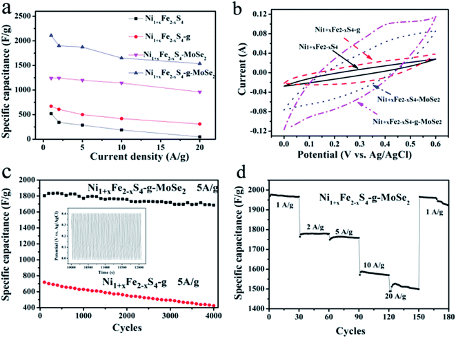
The electrochemical performances of all samples were investigated by galvanostatic charge–discharge (GCD) and CV measurements in 6 M KOH as the electrolyte. The GCD curves were measured in the potential window of 0–0.4 V, and the data are shown in Fig. 4a and S4.† The specific capacitance was calculated according to eqn (1).
 | (1) |
Fig. 4a summarizes the calculated responses of Ni1+xFe2−xS4, Ni1+xFe2−xS4-g, Ni1+xFe2−xS4-MoSe2 and Ni1+xFe2−xS4-g-MoSe2 at different current densities ranging from 1 to 20 A g−1. Apparently, the addition of graphene and MoSe2 nanosheets enhanced the SC composed of ternary composite-a product due to the effective electrochemical utilization of Ni1+xFe2−xS4. The Ni1+xFe2−xS4-g-MoSe2 composite exhibited excellent capacitance reaching up to 2108, 1898, 1872, 1650 and 1536 F g−1 at current densities of 1, 2, 5, 10 and 20 A g−1, respectively. These values were much higher than those obtained with the Ni1+xFe2−xS4-based counterparts.
As shown in the CV of Fig. 4b and S5,† the area surrounded by the CV curve of Ni1+xFe2−xS4-g-MoSe2 in the three-electrode systems was the largest, meaning a highest capacitance when compared to other Ni1+xFe2−xS4-containing samples. The material amount and device capacitance (Cm, F g−1) can be calculated using the CV measurements and eqn (2).
 | (2) |
Long cycle life is another imperative criterion of commercial SCs. To confirm the advantages of the ternary composite in the effective electrochemical utilization of Ni1+xFe2−x and MoSe2, long cycle charge–discharge testing was conducted for Ni1+xFe2−x-g and Ni1+xFe2−x-g-MoSe2, and the results are shown in Fig. 4c. Compared to Ni1+xFe2−x-g, the Ni1+xFe2−x-g-MoSe2 composite exhibited far higher specific capacitance and cycling stability values. The specific capacitance initially increased due to the full activation of Ni1+xFe2−xS4, with no obvious degradation of the active material after 4000 cycles retaining 93.3% of the initial capacity. Fig. 4d illustrated that bringing the current density to 1 A g−1 after one whole cycle induced no significant change in the specific capacitance. This further confirmed the excellent electrochemical stability and rate capability of Ni1+xFe2−xS4-g-MoSe2.
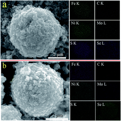
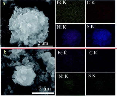
To gain a better understanding of the long-life performance of Ni1+xFe2−xS4-g-MoSe2, the material was extracted from the electrode, washed with dimethyl carbonate, then the morphology and composition were examined with SEM and EDX mapping and the results were compared with previously untested samples (Fig. 5a). The color maps revealed the homogeneous distribution of Ni, Fe and S throughout the entire particles of C, Mo, and Se nanosheets. Furthermore, even after 4000-cycle of testing, the SEM and EDX mapping of Ni1+xFe2−xS4-g-MoSe2 appeared essentially identical to the original samples (Fig. 5b). This suggested that the morphology and composition of the Ni1+xFe2−xS4-g-MoSe2 nanocomposites underwent no change during cycling. By contrast, the SEM and EDX mappings of Ni1+xFe2−xS4-g before and after cycle tests varied greatly (Fig. 6).
Based on the experimental results, the unique performance of Ni1+xFe2−xS4-g-MoSe2 nanocomposite could be explained by the following mechanism: first, the graphene sheets significantly facilitated the electron transport during the charge and discharge processes due to their high conductivities. This was confirmed by the EIS results shown in Fig. 7a. Also, they accelerated the ion diffusion demonstrated by the converted UV-Vis absorption spectra in Fig. 7b. Secondly, MoSe2 served as a mechanical buffer to alleviate the volume change during the charge and discharge processes. Also, Ni1+xFe2−xS4 nanoparticles were strongly anchored into the graphene nanosheets because of their stable structures. Furthermore, the Ni1+xFe2−xS4 particles acted as a spacer, preventing the graphene and MoSe2 nanosheets from agglomerations. Thirdly, it is well-known that a higher specific surface areas and larger pore volumes of composites are beneficial for enhancing the photocatalytic performance. The N2 adsorption–desorption isotherm of Ni1+xFe2−xS4, Ni1+xFe2−xS4-g and Ni1+xFe2−xS4-g-MoSe2 are shown in Fig. S6,† the specific surface areas of Ni1+xFe2−xS4, Ni1+xFe2−xS4-g and Ni1+xFe2−xS4-g-MoSe2 are 9.5, 34.5 and 49.2 m2 g−1, respectively. Finally, the synergistic effect due to the three components in Ni1+xFe2−xS4-g-MoSe2 resulted in enhanced electrochemical properties, where graphene provided fast ion/electron transfer, Ni1+xFe2−xS4 boosted the supercapacity of the nanocomposite, and MoSe2 improved the cycling stability.
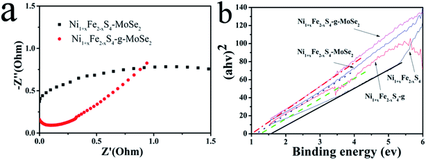 | ||
| Fig. 7 (a) EIS curves of Ni1+xFe2−xS4-MoSe2 and Ni1+xFe2−xS4-g-MoSe2 and (b) DRS curves of Ni1+xFe2−xS4, Ni1+xFe2−xS4-g, Ni1+xFe2−xS4-MoSe2, and Ni1+xFe2−xS4-g-MoSe2. | ||
5. Conclusions
Ternary Ni1+xFe2−xS4-g-MoSe2 was prepared for the first time through a two-step hydrothermal method followed by in situ absorption. The resulting microstructures consisted of well-dispersed MoSe2 and graphene nanosheets connected with Ni1+xFe2−xS4 nanoparticles. The obtained Ni1+xFe2−xS4-g-MoSe2 demonstrated superior electrochemical performances attributed to the synergistic effect between the 2D MoSe2, highly conductive graphene networks, Ni1+xFe2−xS4 nanoparticles, and the stable three-dimensional architecture supporting each component. Thus, the sheet-sphere-sheet nanostructure was extremely stable during long-life charge–discharge processes, resulting in improved rate capability and cycling stability. The evaluation of Ni1+xFe2−xS4-g-MoSe2 as electrode active material for SC revealed high specific capacitance and excellent cyclic stability. Moreover, the constructed electrodes from this material exhibited rapid electron and ion transport rates, with large electroactive surface areas. These findings indicated Ni1+xFe2−xS4-g-MoSe2 as a promising electrode material for SC applications.Conflicts of interest
There are no conflicts to declare.References
- D. Cai, D. Wang, B. Liu, Y. Wang, Y. Liu, L. Wang, H. Li, H. Huang, Q. Li and T. Wang, ACS Appl. Mater. Interfaces, 2013, 5, 12905–12910 CAS.
- P. Xiong, H. Huang and X. Wang, J. Power Sources, 2014, 245, 937–946 CrossRef CAS.
- Z.-L. Wang, X.-J. He, S.-H. Ye, Y.-X. Tong and G.-R. Li, ACS Appl. Mater. Interfaces, 2014, 6, 642–647 CAS.
- Y. Zhao, L. Zhan, J. Tian, S. Nie and Z. Ning, Electrochim. Acta, 2011, 56, 1967–1972 CrossRef CAS.
- B. D. Boruah and A. Misra, ACS Energy Lett., 2017, 2, 1720–1728 CrossRef CAS.
- X. Li, H. Xue and H. Pang, Nanoscale, 2017, 9, 216–222 RSC.
- X. Chia, A. Ambrosi, Z. Sofer, J. Luxa and M. Pumera, ACS Nano, 2015, 9, 5164–5179 CrossRef CAS PubMed.
- S. Peng, L. Li, H. B. Wu, S. Madhavi and X. W. Lou, Adv. Energy Mater., 2015, 5, 1401172 CrossRef.
- L. Cao, S. Yang, W. Gao, Z. Liu, Y. Gong, L. Ma, G. Shi, S. Lei, Y. Zhang, S. Zhang, R. Vajtai and P. M. Ajayan, Small, 2013, 9, 2905–2910 CrossRef CAS PubMed.
- W. Cai, T. Lai, W. Dai and J. Ye, J. Power Sources, 2014, 255, 170–178 CrossRef CAS.
- B. D. Boruah and A. Misra, J. Mater. Chem. A, 2016, 4, 17552–17559 CAS.
- B. Li, P. Gu, Y. Feng, G. Zhang, K. Huang, H. Xue and H. Pang, Adv. Funct. Mater., 2017, 27, 1605784 CrossRef.
- X. Wang, B. Liu, R. Liu, Q. Wang, X. Hou, D. Chen, R. Wang and G. Shen, Angew. Chem., Int. Ed., 2014, 53, 1849–1853 CrossRef CAS PubMed.
- Y. Chen, B. Liu, Q. Liu, J. Wang, J. Liu, H. Zhang, S. Hu and X. Jing, Electrochim. Acta, 2015, 178, 429–438 CrossRef CAS.
- X. Li, S. Ding, X. Xiao, J. Shao, J. Wei, H. Pang and Y. Yu, J. Mater. Chem. A, 2017, 5, 12774–12781 CAS.
- H. Pang, X. Li, Q. Zhao, H. Xue, W.-Y. Lai, Z. Hu and W. Huang, Nano Energy, 2017, 35, 138–145 CrossRef CAS.
- S. Chen and S.-Z. Qiao, ACS Nano, 2013, 7, 10190–10196 CrossRef CAS PubMed.
- H. Jiang, Y. Dai, Y. Hu, W. Chen and C. Li, ACS Sustainable Chem. Eng., 2014, 2, 70–74 CrossRef CAS.
- Y. Xu, G. Shi and X. Duan, Acc. Chem. Res., 2015, 48, 1666–1675 CrossRef CAS PubMed.
- M.-C. Liu, L.-B. Kong, C. Lu, X.-J. Ma, X.-M. Li, Y.-C. Luo and L. Kang, J. Mater. Chem. A, 2013, 1, 1380–1387 CAS.
- L.-Q. Mai, F. Yang, Y.-L. Zhao, X. Xu, L. Xu and Y.-Z. Luo, Nat. Commun., 2011, 2, 381 CrossRef PubMed.
- L. Huang, D. Chen, Y. Ding, Z. L. Wang, Z. Zeng and M. Liu, ACS Appl. Mater. Interfaces, 2013, 5, 11159–11162 CAS.
- Y. Song, T.-Y. Liu, X.-X. Xu, D.-Y. Feng, Y. Li and X.-X. Liu, Adv. Funct. Mater., 2015, 25, 4626–4632 CrossRef CAS.
- G. Ćirić-Marjanović, Synth. Met., 2013, 170, 31–56 CrossRef.
- H. Ben, M. Julian, W. Shuang, I. Jung Bin, C. Carlo, P. Dimos, P. G. Costas and M. Roya, Nanotechnology, 2014, 25, 055401 CrossRef PubMed.
- G. Nystrom, A. Marais, E. Karabulut, L. Wagberg, Y. Cui and M. M. Hamedi, Nat. Commun., 2015, 6, 7259 CrossRef PubMed.
- E. G. da Silveira Firmiano, A. C. Rabelo, C. J. Dalmaschio, A. N. Pinheiro, E. C. Pereira, W. H. Schreiner and E. R. Leite, Adv. Energy Mater., 2014, 4, 175–178 Search PubMed.
- H. Hu, K. Zhang, S. Li, S. Ji and C. Ye, J. Mater. Chem. A, 2014, 2, 20916–20922 CAS.
- S. Peng, L. Li, C. Li, H. Tan, R. Cai, H. Yu, S. Mhaisalkar, M. Srinivasan, S. Ramakrishna and Q. Yan, Chem. Commun., 2013, 49, 10178–10180 RSC.
- D. Guo, P. Zhang, H. Zhang, X. Yu, J. Zhu, Q. Li and T. Wang, J. Mater. Chem. A, 2013, 1, 9024–9027 CAS.
- Y. Zhang, W. Sun, X. Rui, B. Li, H. T. Tan, G. Guo, S. Madhavi, Y. Zong and Q. Yan, Small, 2015, 11, 3694–3702 CrossRef CAS PubMed.
- L. Niu, Z. Li, Y. Xu, J. Sun, W. Hong, X. Liu, J. Wang and S. Yang, ACS Appl. Mater. Interfaces, 2013, 5, 8044–8052 CAS.
- M.-C. Liu, L.-B. Kong, C. Lu, X.-M. Li, Y.-C. Luo and L. Kang, ACS Appl. Mater. Interfaces, 2012, 4, 4631–4636 CAS.
- G. Wang, Q. Tang, H. Bao, X. Li and G. Wang, J. Power Sources, 2013, 241, 231–238 CrossRef CAS.
- K.-J. Huang, L. Wang, Y.-J. Liu, H.-B. Wang, Y.-M. Liu and L.-L. Wang, Electrochim. Acta, 2013, 109, 587–594 CrossRef CAS.
- R. B. Rakhi, W. Chen, D. Cha and H. N. Alshareef, Adv. Energy Mater., 2012, 2, 381–389 CrossRef CAS.
- J.-G. Wang, Y. Yang, Z.-H. Huang and F. Kang, J. Mater. Chem., 2012, 22, 16943–16949 RSC.
- N. Kurra, C. Xia, M. N. Hedhili and H. N. Alshareef, Chem. Commun., 2015, 51, 10494–10497 RSC.
- X. Zhang, Z. Lin, B. Chen, W. Zhang, S. Sharma, W. Gu and Y. Deng, J. Power Sources, 2014, 246, 283–289 CrossRef CAS.
- X. Yu, B. Lu and Z. Xu, Adv. Mater., 2014, 26, 1044–1051 CrossRef CAS PubMed.
- M. S. Javed, S. Dai, M. Wang, D. Guo, L. Chen, X. Wang, C. Hu and Y. Xi, J. Power Sources, 2015, 285, 63–69 CrossRef CAS.
- M. Acerce, D. Voiry and M. Chhowalla, Nat. Nanotechnol., 2015, 10, 313–318 CrossRef CAS PubMed.
- J. N. Coleman, M. Lotya, A. O'Neill, S. D. Bergin, P. J. King, U. Khan, K. Young, A. Gaucher, S. De, R. J. Smith, I. V. Shvets, S. K. Arora, G. Stanton, H.-Y. Kim, K. Lee, G. T. Kim, G. S. Duesberg, T. Hallam, J. J. Boland, J. J. Wang, J. F. Donegan, J. C. Grunlan, G. Moriarty, A. Shmeliov, R. J. Nicholls, J. M. Perkins, E. M. Grieveson, K. Theuwissen, D. W. McComb, P. D. Nellist and V. Nicolosi, Science, 2011, 331, 568–571 CrossRef CAS PubMed.
- P. Hu, T. Chen, Y. Yang, H. Wang, Z. Luo, J. Yang, H. Fu and L. Guo, Nanoscale, 2017, 9, 1423–1427 RSC.
- B. D. Boruah, A. Maji and A. Misra, Nanoscale, 2017, 9, 9411–9420 RSC.
- S. K. Balasingam, J. S. Lee and Y. Jun, Dalton Trans., 2015, 44, 15491–15498 RSC.
- V. Nicolosi, M. Chhowalla, M. G. Kanatzidis, M. S. Strano and J. N. Coleman, Science, 2013, 340, 6139 CrossRef.
- T. Heine, Acc. Chem. Res., 2015, 48, 65–72 CrossRef CAS PubMed.
- X. Tang, Z. Yang and J. Liang, RSC Adv., 2016, 6, 88168–88173 RSC.
Footnote |
| † Electronic supplementary information (ESI) available. See DOI: 10.1039/c7ra08785c |
| This journal is © The Royal Society of Chemistry 2017 |

