 Open Access Article
Creative Commons Attribution 3.0 Unported Licence
pH-Responsive nanofiltration membranes based on porphyrin supramolecular self-assembly by layer-by-layer technique†
Chenglin
Wu
 *a,
Lizhi
Zhao
*b and
Yuzhong
Zhang
b
aSchool of Pharmaceutical and Chemical Engineering, Taizhou University, Taizhou, Zhejiang Province 318000, P. R. China. E-mail: polyclwu@126.com; Fax: +86-576-88660177; Tel: +86-576-88660177
bState Key Laboratory of Separation Membranes and Membrane Processes, School of Materials Science and Engineering, Tianjin Polytechnic University, Tianjin, 300387, P. R. China. E-mail: zhaolizhi_phd@163.com
First published on 9th October 2017
Abstract
A novel pH-responsive nanofiltration membrane was fabricated by means of layer-by-layer (LbL) technique based on porphyrin supramolecular self-assembly. The multilayer membrane was prepared on a hydrolyzed poly(acrylonitrile) (PAN) support membrane, and was composed of poly(allylamine hydrochloride) (PAH) as a polycation and poly(styrene sulfonate) (PSS) as a polyanion and 5,10,15,20-tetrakis-(4-sulfonatophenyl)-porphyrin (TPPS) as the pH-responsive functional supramolecular. Aggregation of TPPS and the shielding effect of salt in solution affected the adsorption of TPPS onto the membrane, while the higher ionization degree of the oppositely charged membrane with PAH favored the adsorption of TPPS. A coil structure of polyelectrolytes caused by the lower ionization degree of PAH or by the shielding effect of salt led to higher adsorption of polyelectrolytes on the membrane. The LbL assembly membrane showed higher and pH-responsive water flux and salt rejection compared with that without TPPS. At pH 1.0, TPPS assembled into J-aggregates on the membrane surface, and the membrane showed relatively lower water flux and higher rejection. When the pH value was increased above 2.0, TPPS transformed into H-aggregates and monomers, and the membrane showed relatively higher water flux and lower salt rejection.
1. Introduction
Nanofiltration (NF) membranes with separation characteristics falling in the range between reverse osmosis (RO) and ultrafiltration (UF) membranes have gained lots of attention due to their utility in various industrial fields for selective separation processes at low applied pressures.1–3 Currently, most commercial NF membranes are prepared by phase inversion,4,5 interfacial polymerization,6–9 and post-treatment of a more porous support (surface coatings, grafting, etc.).10,11 However, these technical controls are often more complicated, and there are many factors that can effect the structures and properties of the membranes.The layer-by-layer (LbL) approach based on self-assembly of charged polyelectrolytes on an oppositely charged porous support to fabricate NF membranes has attracted great attention recently.12–16 Polyelectrolytes assembly is driven by electrostatic interactions and by entropic considerations related to the liberation of counterions during assembly. LbL approach to fabricating NF membranes can provide number of advantages. It can provide the potential to accurately control membrane thickness on the nanometer-scale, and there is a degree of self-healing from the fabrication process, and the separation properties of membrane can be readily controlled via the types of the polyelectrolyte used, numbers of applied layers, polymer compositions, concentration, pH and ionic strength during coating.1 In particular, the materials can be low-cost, water soluble and commercially available polymers.
Stimuli responsive membranes can alter their physiochemical properties when subjected to specific external environmental conditions such as pH, temperature, ionic strength, and so forth.2,15–22 These physicochemical changes can lead to changes in their permeability and selectivity. Since pH is a crucial parameter and easy to be adjusted in membrane separations, pH-responsive membranes have attracted great attention. Most of pH-responsive membranes composed of porous membrane substrates and surface-tethered pH-responsive polymer chains are fabricated by surface graft or phase inversion method.23–27 Qian et al. proposed pH-responsive membranes for sugar separations based on surface modified by grafting poly(acrylic acid) (PAA) nano-chains using a UV initiated free radical polymerization method, and pH dramatically affected the membrane performance and selectivity that be used to separate monosaccharides, disaccharides, and their mixtures.23 Chu et al. prepared pH-responsive membranes by grafting diblock polymers of poly(N-isopropylacrylamide)-b-poly(methacrylic acid) (PNIPAM-b-PMAA) onto nylon-6 membrane substance pore surfaces using atom transfer radical polymerization.24 In our earlier studies, we developed pH-responsive membranes by grafting poly(4-vinylpyridine) (P4VP) chains from the surface of commercial PSF membranes28 and grafting poly(2-(dimethylamino)ethylmethylacrylate) (PDMAEMA) chains from the surface of ethylene vinyl alcohol (EVAL) membranes.29 The pH-responsive functions are achieved through the shrinking/swelling conformational transitions of the pH-responsive polymer chains. The membrane pores could be changed to open/close with pH value and hence the permeability and selectivity of the membrane was manipulated. However, the study on pH-responsive membranes mainly focused on introducing pH-responsive polymers into membranes, which required complicated synthesis process. The size of membrane pore changed by pH-responsive polymer chains was too large to be applied in NF for charge-based separations.
Self-assembly offers an attractive method for the development of supramolecular nanostructures. Porphyrins are excellent spare materials to assemble into supramolecular architectures. Particularly, 5,10,15,20-tetrakis-(4-sulfonatophenyl)-porphyrin (TPPS) can form two types of aggregates, which are J-aggregates (edge-to-edge stacking) and H-aggregates (face-to-face stacking) under different pH conditions.30 A sheet-like architecture of molecules builds J-aggregates, which are found to be remarkably nano-rods with a large aggregation number,31,32 while H-aggregates have a dimeric structure.33 TPPS self-assemblies have been used to design biomaterial sensors and opto-electronic devices because of their excellent spectroscopic properties.34–36 We have recently reported a pH-responsive smart UF membrane with the aid of aggregates transformation of TPPS.37 It was the supramolecular assembly that constituted the switchable gate of intelligent membrane based on the contrast between J- and H-aggregates. The porphyrin was loaded on a PDMAEMA-grafted membrane which also required a chemical modification. Within this framework, the porphyrin supramolecular self-assembly was formed on the membrane via an LbL technique. The hydrolyzed poly(acrylonitrile) (PAN) was used as the support membrane, and poly(allylamine hydrochloride) (PAH) as the polycation while poly(styrene sulfonate) (PSS) as the polyanion. The supramolecular self-assembly of TPPS was loaded in the polyelectrolyte layers based on electrostatic interaction with PAH chains. The delicate pH-dependent transformation between J- and H-aggregates was employed to fabricate pH-responsive NF membrane.
2. Experimental section
2.1 Materials
PSS (Mw = 70![[thin space (1/6-em)]](https://www.rsc.org/images/entities/char_2009.gif) 000 Da), PAH (Mw = 15
000 Da), PAH (Mw = 15![[thin space (1/6-em)]](https://www.rsc.org/images/entities/char_2009.gif) 000 Da) and 5,10,15,20-tetrakis-(4-sulfonatophenyl)-porphyrin (TPPS, >95%) were obtained from J&K Chemicals and used without further purification. PAN (Mw = 150
000 Da) and 5,10,15,20-tetrakis-(4-sulfonatophenyl)-porphyrin (TPPS, >95%) were obtained from J&K Chemicals and used without further purification. PAN (Mw = 150![[thin space (1/6-em)]](https://www.rsc.org/images/entities/char_2009.gif) 000 Da) was purchased from Tianjin Kemiou Chemical Reagent Co., Ltd and used as received. All the other chemicals were analytical reagents and used as received. Deionized water purified with a Milli-Q system (Millipore) was used in this study.
000 Da) was purchased from Tianjin Kemiou Chemical Reagent Co., Ltd and used as received. All the other chemicals were analytical reagents and used as received. Deionized water purified with a Milli-Q system (Millipore) was used in this study.
2.2 Preparation of support membrane
The original PAN membrane was prepared by a phase inversion method. PAN and lithium chloride (LiCl, 99%) were dissolved in N,N-dimethylformamide (DMF, 97%). The solution was stirred for 6 h at 60 °C, and then degassed for 1 h under vacuum to eliminate bubbles. The solution was cast on a glass plate using a steel knife with a gap height of 200 μm. The cast film was immersed into a deionized water bath at 25 °C until the membrane was peeled off from the glass plate. The obtained original PAN membrane was washed with deionized water to remove the residual solvent, and then dried at room temperature for further modification and characterizations.The charged PAN support was prepared using a procedure reported earlier with slightly modified.13 PAN membrane was hydrolyzed by immersing in a NaOH solution (1.5 M) at 40 °C for 1.5 h, and then neutralized by rinsing with deionized water. After the process, the –CN groups on PAN membrane were transformed to –COOH groups, which could benefit assembling the first positively charged PAH layer. The original PAN membrane and PAN–COOH membrane were characterized by attenuated total reflectance Fourier transform infrared spectroscopy (ATR-FTIR) (Bruker Vector 22).
2.3 Preparation of LbL assembly membrane
The PAN–[PAH/(PSS–TPPS)]n membrane, where n represented number of layers, was prepared by LbL assembly of PAH and PSS–TPPS on the PAN–COOH membrane alternately. PAH was dissolved into a buffer solution at a concentration of 1.0 g L−1. PSS–TPPS was prepared in the same buffer solution at concentrations of 1.0 g L−1 and 65 μM, respectively. The PAN–COOH substrate membrane was first immersed into PAH solution for 15 min and then rinsed with deionized water for four times. After dried under nitrogen gas, the substrate was immersed into PSS–TPPS solution for another 15 min and then rinsed and dried. This cycle was repeated with oppositely charged species until the desired architecture was achieved.The polyelectrolyte layers were cross-linked by glutaraldehyde (GA) to improve the stability of LbL assembly membrane. The PAN–[PAH/(PSS–TPPS)]n membrane was added into 0.1 wt% GA solution for different time (0, 60, 100, 120, and 150 min), and then rinsing with deionized water for 30 min to remove the residual GA.
2.4 Characterization
The water contact angle of membrane was measured via a sessile drop method using a contact angle measurement apparatus (CM3250, KRUSS GmbH, Germany) equipped with video capture. The membranes were dried under nitrogen gas and then dried overnight at room temperature prior to the contact angle measurements. For each membrane, average of 6–8 measurements was taken to minimize the experimental error.Ultraviolet-visible (UV-vis) absorption and solid-state diffuse reflectance UV-vis (DRUV) spectra were measured on a TU-1901 UV-vis spectrophotometer (Purkinje General, China).
The surface and cross-section morphology of membranes were characterized by field emission electron microscopy (FESEM, Hitachi S-4800, Japan) under high vacuum conditions.
The surface morphology and roughness of dry membranes were measured by atomic force microscopy (AFM) recorded using a Multimode IIIA scanning probes. Imaging was done in tapping mode at ambient condition using a silicon RTESPA probe.
The outer surface zeta potential of the membrane was measured using the Sur Pass Electrophoretic Analyzer (Anton-Paar GmbH, Austria) in 0.001 M KCl solution. Each data point represents an average of five measurements for each membrane. The outer surface zeta potential was estimated using the Helmholtz–Smoluchowski equation as given below:38,39
2.5 Nanofiltration experiments
The separation performance of the membrane was determined using a home-made stainless steel disc with an effective filtration area of 22.9 cm2. Before test, the membranes were equilibrated with buffer solutions at each pH for 10 h, and the system was first pressurized at 0.2 MPa for 30 min until the flux reach a steady state. The concentration of MgSO4 was 2.0 g L−1. The water flux (J) was calculated using the following equation:where J is the water flux (L m−2 h−1); V is the permeate volume (L); A is the effective membrane area (m2); t is the filtration time (h).
The salt rejection (R) was calculated as following:
3. Results and discussion
3.1 Preparation of LbL membrane
ATR-FTIR was used to confirm the hydrolysis of the PAN support (Fig. S1†). The peaks at 2243 cm−1 and 1451 cm−1 are due to stretching vibrations of the CN moiety of the PAN membrane.40 After hydrolysis of PAN membrane, a peak reduction at 2243 cm−1 and the emergence of new peaks at 1560 cm−1 and 1405 cm−1 corresponding to the C![[double bond, length as m-dash]](https://www.rsc.org/images/entities/char_e001.gif) O bond in the COOH groups proved that most of the CN groups on the membrane surface converted to COOH groups.41
O bond in the COOH groups proved that most of the CN groups on the membrane surface converted to COOH groups.41
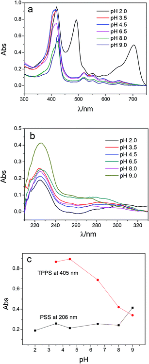
Multilayer of PAH/(PSS–TPPS) was assembled on PAN–COOH membrane surfaces by layer-by-layer method due to electrostatic interaction (Scheme 1). The pH and ionic strength of PAH and PSS–TPPS solutions may influence the structure and properties of the multilayer. PAH is a weak base, and the pKa is about 9.0. The charge and extension of PAH chain change with pH value. The DRUV was used to investigate the adsorption capacity of TPPS and PSS at different pH values of PAH solution (Fig. 1). At pH 2.0 of PAH solution, B bands and Q bands of TPPS were red shifted to 490 nm and 705 nm (Fig. 1a), which indicated that TPPS molecules self-assembled into J-aggregates on the membrane surface. When pH value of PAH solution was increased above 3.5, the bands at about 405 nm and 422 nm can be observed, which suggested that H-aggregates and monomers of TPPS coexisted on the membrane surface. In addition, the absorption intensity of TPPS on the membrane was higher at pH 2.0 than at pH above 3.5, and the absorption intensity at 422 nm was decreased with increased pH value (Fig. 1a). This is because the charge of PAH was reduced with increased pH value and the electrostatic interaction between PAH and TPPS was weakened leading to lower adsorption capacity of TPPS. At pH 9.0, the shoulder at 405 nm presenting H-aggregates of TPPS disappeared, which means TPPS existed as only monomer on the membrane because of quite low adsorption capacity. Then the absorption intensity at 405 nm was used to evaluate the amount of TPPS adsorbed on membrane. The trend of decreasing adsorption capacity of TPPS can be obviously observed in Fig. 1c. By contrast, larger adsorption capacity of polyelectrolytes on the membrane was obtained at higher pH value of PAH solution. The band at 226 nm attributing to the benzene of PSS showed an increased intensity when pH value of PAH solution was increased to 9.0 (Fig. 1b and c). Because, at pH above pKa of PAH, the electrostatic repulsion between positively charged groups on PAH was weakened and the extended chain changed to a coil structure, which allowed more PAH chains to attach to the membrane and favored the adsorption of PSS consequently.
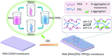 | ||
| Scheme 1 Schematic model of LbL assembly membrane fabrication and pH-responsive structure of the TPPS assembly. | ||
The top surface morphologies and roughness of the PAN–[PAH/(PSS–TPPS)]6 membranes prepared with different pH value of PAH solutions were investigated by AFM. As shown in Fig. 2, the surface of PAN support membrane was smooth, and the root-mean-square (RMS) which was used to evaluate the surface roughness was about 19.6 nm. The RMS of PAN–[PAH/(PSS–TPPS)]6 membranes prepared with PAH pH values of 2.0, 4.5, and 9.0 were 23.2 nm, 36.3 nm, and 46.0 nm, respectively. The roughness increased with increased pH value of PAH solution because of the increasing adsorption capacity of PSS and PAH.42
 | ||
| Fig. 2 AFM images of PAN support membrane (A); and PAN–[PAH/(PSS–TPPS)]6 membranes prepared from PSS–TPPS solutions at pH 6.5 and PAH solutions at pH values of 2.0 (B), 4.5 (C), and 9.0 (D). | ||
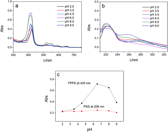
PSS is a strong polyelectrolyte, and the charge and the configuration of PSS are not pH-dependent. Thus adsorption capacity of PSS on membrane is supposed to be unchanged as the pH of PSS–TPPS changes. However, the pH value of PSS–TPPS solution could influence the ionization degree of PAH on the membrane and the aggregation of TPPS in solution. Fig. 3 shows the DRUV spectra of PAN–[PAH/(PSS–TPPS)]6 membranes prepared at different pH values of PSS–TPPS. The absorption intensity of TPPS increased first and then decreased with increased pH value of PSS/TPPS solution (Fig. 3a and c). The lower adsorption capacity of TPPS at lower pH was due to the J-aggregation of TPPS formed in solution at pH 2.0 which affected the adsorption of TPPS on membrane. At pH above 8.0, the decreased adsorption capacity of TPPS may be caused by the decreased ionization degree of PAH adsorbed on the membrane. The increased concentration of OH− may also play a role in shielding the interaction between TPPS and PAH. The decrease in adsorption capacity of PSS at higher pH was not significant (Fig. 3b and c), because the multiple-point cooperative binding of polyelectrolytes allowed considerable amounts of PSS to interact with PAH.
As shown in Fig. 4, the RMS of PAN–[PAH/(PSS–TPPS)]6 membranes prepared with PSS–TPPS solutions at pH values of 2.0, 4.5, and 8.0 were 42.4 nm, 44 nm, and 44.8 nm, respectively. The nearly unchanged roughness also indicated little changes in the adsorption capacity of polyelectrolytes when different pH values of PSS/TPPS solutions were applied.
 | ||
| Fig. 4 AFM images of PAN–[PAH/(PSS–TPPS)]6 membranes prepared from PAH solutions at pH 6.5 and PSS–TPPS solutions at pH values of 2.0 (A), 4.5 (B), and 8.0 (C). | ||
To investigate the influence of the ionic strength on polyelectrolyte multilayer forming, LbL assembly experiments were conducted in buffers with variable salt concentrations. A set of DRUV spectra of PAN–[PAH/(PSS–TPPS)]6 membranes obtained at different ionic strengths varied from 0 to 1.2 M is depicted in Fig. 5. It is clearly seen that the adsorption capacity of TPPS decreased (Fig. 5a) and that of PSS increased (Fig. 5b) when ionic strength increased. It is clear that ions of high concentration shielded the interaction between TPPS and polyelectrolytes. As for polyelectrolyte, at low ionic concentration, polyelectrolyte chains normally present an extended conformation, while at higher ionic strength, they tend to coil because salt ions shield the electrostatic repulsion between charged groups of polyelectrolytes.43,44 That is the reason why more PSS were loaded on membrane surface at higher ionic strength. As shown in Fig. 6, the surface of PAN–[PAH/(PSS–TPPS)]6 membrane became rougher as ionic strength increased. The RMS were 25.6 nm, 47.4 nm, 53.6 nm, and 71.4 nm for PAN–[PAH/(PSS–TPPS)]6 membranes prepared at ionic concentration of 0 M, 0.3 M, 0.8 M, and 1.2 M because of more polyelectrolytes adsorbed onto the membrane. All these results above showed that the adsorption of TPPS onto the membrane was determined only by electric attraction, while the assembly of polyelectrolytes depended on chain configuration as well as electrostatic interaction.
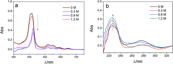 | ||
| Fig. 5 DRUV spectra of PAN–[PAH/(PSS–TPPS)]6 membranes prepared at different ionic strengths (TPPS (a) and PSS (b)). | ||
 | ||
| Fig. 6 AFM images of PAN–[PAH/(PSS–TPPS)]6 membranes prepared at different ionic strengths (0 (A), 0.3 (B), 0.8 (C), and 1.2 (D)). | ||
3.2 Surface properties of LbL membrane
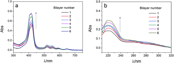
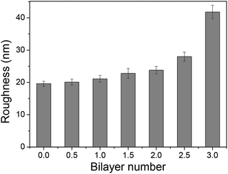
The adsorption capacity of TPPS and polyelectrolytes on the membrane grew as depositing more polymer/TPPS films. Fig. 7 shows the DRUV spectra of PAN–[PAH/(PSS–TPPS)]n membranes with different number of bilayer prepared at pH 6.5 and 0.5 M of ionic strength. It is obviously seen that the absorption of TPPS (Fig. 7a) and PSS (Fig. 7b) increased with increasing bilayer number. Further, the surface properties of the layers were of particular importance to the transport processes occurring at the interface between the electrolyte solutions and the multilayer. Herein, we prepared PSS–TPPS-terminated (T-PSS–TPPS) layers (n = 1.0, 2.0, 3.0…) and PAH-terminated (T-PAH) layers (n = 0.5, 1.5, 2.5, 3.5…) to investigate the surface properties of the layers. The experimental results for the PAN–COOH substrate were also displayed as a reference for comparative study.Membrane surface roughness increased with the increased number of polyelectrolyte layers (Fig. 8), which could be attributed to the random adsorption of the polyelectrolytes.31 As increasing bilayer number, the roughness had an increasing tendency for both T-PSS–TPPS and T-PAH layers.
The values of the zeta potential reflected the surface electric properties because they were the electric potential difference between the mobile diffusion layer on the charged surface and the bulk solution. The sign of the surface charge was reversed. For PAN–(PAH/PSS)n membrane without TPPS, and a positive value of +25 mV was yielded when the first PAH layer was deposited on the negatively charged PAN–COOH substrate (n = 0.5) (Fig. S2†). After depositing the next negatively charged PSS, the zeta potential of layer was reversed to −40 mV. As depositing more layers of the polyelectrolyte film, oscillatory changes of the surface potential were displayed with amplitudes about 60 mV. PSS-terminated layers gave rise to a higher potential absolute value compared to PAH-terminated layers because of the strong polyelectrolyte PSS. It is also noted that, as for PAN–[PAH/(PSS–TPPS)]n membrane, TPPS enhanced the amplitudes, especially increased the potential absolute value of PSS–TPPS-terminated layers. This made it possible to enhance membrane salt rejection that was strongly influenced by electrostatic repulsion.
The contact angle measurement is a useful method to observe changes in the surface hydrophilicity of the membranes. As shown in Fig. 9, contact angle of PAN–COOH support membrane is about 52°. The coating of polyelectrolytes on the membrane support in all cases led to higher contact angles. As increasing the number of bilayer, little difference in contact angle value of the same type of terminating layer was observed. However, contact angle values of T-PSS–TPPS layer were lower than those of T-PAH layers. That is to say, the PSS–TPPS-terminated membrane is more hydrophilic as compared to the PAH-terminated membrane, because sulfonic acid groups are more easily to form hydrogen bond with water.
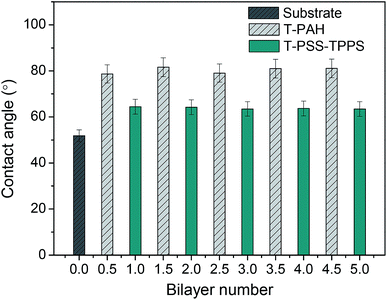 | ||
| Fig. 9 Water contact angles of PAN–[PAH/(PSS–TPPS)]6 membranes with different layers prepared at 0.5 M of salt and pH 6.5. | ||
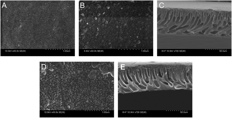
The morphology of PAN–COOH substrate membrane and PAN–[PAH/(PSS–TPPS)]6 membrane was studied by field emission scanning electron microscopy (FESEM) as shown in Fig. 10. It can be seen that the top surface image of the PAN–COOH membrane (Fig. 10A) was quite smooth and the bottom surface (Fig. 10B) had an open pore structure. The immobilization of PAH/(PSS–TPPS) multilayer destroyed the top surface smoothness (Fig. 10D). However, almost no change was observed on the bottom surface after LbL assembly, indicating that the deposition of polyelectrolytes and TPPS mainly occurred on the top surface due to its high functional group density. The cross-section FESEM images of PAN–COOH membrane (Fig. 10C) and PAN–[PAH/(PSS–TPPS)]6 membrane (Fig. 10E) showed an unsymmetrical structure, including a dense separation layer on the top surface, a finger-like middle layer and a sponge-like bottom layer. The assembled layers cannot be distinguished in the cross-section images, which indicated that the layers were very thin.
3.3 pH-Responsive water flux and salt rejection
In order to increase the stability of the self-assembly film in the permeability test, the chemical cross-linking of LbL layer with 0.1 wt% GA was performed, and extra layer PAH/PSS was deposited outside the TPPS-containing layer to immobilize TPPS stably (the membrane was denoted by PAN–[PAH/(PSS–TPPS)]6(PAH/PSS)).The introduction of TPPS increased the charge amount of the assembly layer, and may also change the compact degree of the assembly layer,36 thus affecting the permeability and rejection of the membrane. Fig. 11 shows the water flux and MgSO4 rejection of PAN–[PAH/(PSS/TPPS)]n(PAH/PSS). Obviously, with the increase of bilayer number, the water flux was reduced and the rejection was increased due to the more compact assembly layers. When the bilayer number reached 6, the rejection rate was no longer increased. It is important that, at the same bilayer number, both water flux and rejection of the membrane increased with the initial concentration of TPPS. That is probably because TPPS molecules not only increased the amount of charge of the assembly layer, which enhance the electrostatic repulsion to MgSO4 leading to higher retention, but also acted as an interlayer that allowed more water to pass through.
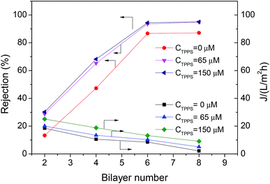 | ||
| Fig. 11 Rejection properties of the PAN–(PAH/PSS–TPPS)n/(PAH/PSS) membranes prepared with different TPPS initial concentrations. The concentration of feed MgSO4 was 2.0 g L−1. | ||
As described above, TPPS can form J-aggregates at lower pH in solution or on assembly layers during assembly layer preparation. The immobilized TPPS on membrane also exhibited pH controlled aggregation behavior. Fig. S3† shows the DRUV spectra of PAN–[PAH/(PSS–TPPS)]6/(PAH/PSS) membranes prepared at pH 6.5 and followed by equilibration with buffers at different pH values for 2 h. At pH 2.0–9.0, the B band of TPPS was 420 nm and had a shoulder at 405 nm, indicating TPPS existed in the form of deprotonated monomer and H-aggregates. The stronger absorption at 9.0 may be caused by the free TPPS molecules released by PAH due to decreased ionization degree. At pH 1.0, the red shifted B band at 490 nm and Q bands at 705 nm showed that TPPS formed J-aggregates. As mentioned in Fig. 1, at pH 2.0 of PAH, the adsorbed TPPS molecules self-assembled into J-aggregates on the membrane surface. While here the immobilized TPPS required lower pH of equilibration buffer to form J-aggregates and the absorption of H-aggregates was weak, because the adsorption capacity of TPPS on membrane prepared from PAH and PSS–TPPS solution at pH 6.5 was lower than that prepared from PSS–TPPS solution at pH 6.5 and PAH solution at pH 2.0.
It has been proved that J-aggregates attached to grafted polymer chains has a large size which can block the pore of the separating membrane layer and then influence the permeability and rejection properties of membrane.29 The supramolecular aggregates of small amount immobilized in LbL assembly layers may be used in the fine structure adjustment and separation property controlling of nanofiltration membranes. As shown in Fig. 12, both water flux and rejection of the membrane PAN–[PAH/(PSS–TPPS)]6/(PAH/PSS) with TPPS were higher than those of PAN–(PAH/PSS)7 without TPPS. More importantly, the water flux and rejection of the membrane without TPPS hardly changed within the pH range; by contrast, a prominent change in the water flux and rejection of PAN–[PAH/(PSS–TPPS)]6/(PAH/PSS) occurred within the pH range of 1.0–2.0. It is the assembly structure of the TPPS aggregates in response to pH on the membrane surface that caused the pH-dependent change in the pore size and the resultant permeability and rejection. At flux pH 1.0, TPPS J-aggregates of larger size blocked the membrane surface pores. On the contrary, at a feed pH above 2.0, J-aggregates transformed to small-sized H-aggregates and monomers and resulted in a larger membrane pore size and higher water permeation rate and lower salt rejection (Scheme 1).
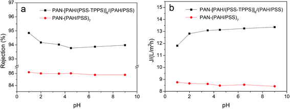 | ||
| Fig. 12 Water flux and rejection of PAN–(PAH/PSS)7 and PAN–[PAH/(PSS–TPPS)]6/(PAH/PSS) membranes at different pH values. | ||
4. Conclusions
In this paper, pH-responsive nanofiltration membrane was fabricated by means of the LbL technique based on TPPS supramolecular self-assembly with hydrolyzed PAN as support membrane and PAH and PSS as the polyelectrolytes. The self-assembly of TPPS and polyelectrolytes onto membrane was influenced by pH and ionic strength of the feed solution. At lower pH of PAH solution, TPPS formed J-aggregates on the membrane and had a higher adsorption capacity, while at higher pH of PAH solution, higher adsorption capacity of polyelectrolytes was obtained due to the coil structure of polymers. Lower pH of PSS and TPPS mixed solution affected the adsorption of TPPS due to J-aggregates of the dye formed in solution. The shielding effect of increased ionic strength resulted in a lower TPPS adsorption but higher polyelectrolyte adsorption. PSS–TPPS-terminated layer showed larger zeta-potential absolute values and better wettability than PAH-terminated layer. The LbL assembly membrane with TPPS showed higher and pH-responsive water flux and MgSO4 rejection compared with that without TPPS. At pH 1.0, TPPS assembled into J-aggregate on the membrane surface, and the membrane showed relatively lower water flux and higher rejection. At a feed pH above 2.0, the membrane showed higher water permeation rate and lower salt rejection due to small-sized H-aggregates and monomers of TPPS. The present systems provide valuable insights into the smart nanofiltration membrane and expand types of smart membrane.Conflicts of interest
There are no conflicts to declare.Acknowledgements
The authors acknowledge financially sponsored of this work by National Natural Science Foundation of China (No. 51403149, 51373120, 21204064), and Science and Technology Commission Foundation of Tianjin (No. 14JCQNJC03900, 15JCZDJC37600).References
- M. Paul and S. D. Jons, Polymer, 2016, 103, 417–456 CrossRef CAS.
- Z. Dang, L. Liu, Y. Li, Y. Xiang and G. Guo, ACS Appl. Mater. Interfaces, 2016, 8, 31281–31288 CrossRef CAS.
- F. Y. Zhao, Q. F. An, Y. L. Ji and C. J. Cao, J. Membr. Sci., 2015, 492, 412–421 CrossRef CAS.
- G. R. Guillen, G. Z. Ramon, H. P. Kavehpour, R. B. Kaner and E. M. V. Hoek, J. Membr. Sci., 2013, 431, 212–220 CrossRef CAS.
- M. Sadrzadeh and S. Bhattacharjee, J. Membr. Sci., 2013, 441, 31–44 CrossRef CAS.
- J. Cheng, W. X. Shi, L. H. Zhang and R. J. Zhang, Appl. Surf. Sci., 2017, 416, 152–159 CrossRef CAS.
- Q. Zhang, L. Fan, Z. Yang, R. N. Zhang, Y. N. Liu, M. R. He, Y. L. Su and Z. Y. Jiang, Appl. Surf. Sci., 2017, 410, 494–504 CrossRef CAS.
- K. P. Lee, G. Bargeman, R. de Rooij, A. J. B. Kemperman and N. E. Benes, J. Membr. Sci., 2017, 523, 487–496 CrossRef CAS.
- K. Yoon, B. S. Hsiao and B. Chu, J. Membr. Sci., 2009, 326, 484–492 CrossRef CAS.
- D. Menne, C. Uzum, A. Koppelmann, J. E. Wong, C. V. Foeken, F. Borre, L. Dahne, T. Laakso, A. Pihlajamaki and M. Wessling, J. Membr. Sci., 2016, 520, 924–932 CrossRef CAS.
- G. Cocchi, M. G. De Angelies and F. Doghieri, J. Membr. Sci., 2015, 492, 612–619 CrossRef CAS.
- N. Joseph and P. Ahmadiannmini, Polym. Chem., 2014, 5, 1817–1831 RSC.
- S. Ilyas, N. Joseph, A. Szymczyk, A. Volodin, K. Nijmeijer, W. M. de Vos and I. F. J. Vankelecom, J. Membr. Sci., 2016, 514, 322–331 CrossRef CAS.
- D. Menne, C. Uzum, A. Koppelmann, J. E. Wong, C. van Foeken, F. Borre, L. Dahne, T. Laakso, A. Pihlajamaki and M. Wessling, J. Membr. Sci., 2016, 520, 924–932 CrossRef CAS.
- Q. Nan, P. Li and B. Cao, Appl. Surf. Sci., 2016, 387, 521–528 CrossRef CAS.
- X. Hu, E. Mclntosh, M. G. Simon, C. Staii and S. W. Thomas, Adv. Mater., 2016, 28, 715–721 CrossRef CAS.
- R. Shevate, M. Karunakaran, M. Kumar and K. V. Peinemann, J. Membr. Sci., 2016, 501, 161–168 CrossRef CAS.
- B. Ma, X. J. Ju, F. Luo, Y. Q. Liu, Y. Wang, Z. Liu, W. Wang, R. Xie and L. Y. Chu, ACS Appl. Mater. Interfaces, 2017, 9, 14409–14421 CrossRef CAS.
- T. Ito and T. Yamaguchi, Langmuir, 2006, 22, 3945–3949 CrossRef CAS.
- F. P. Nicoletta, D. Cupelli, P. Formoso, G. D. Filpo, V. Colella and A. Gugliuzza, Membranes, 2012, 2, 134–197 CrossRef CAS.
- S. Singh, A. Junghans, J. Tian, M. Dubey, S. Gnanakaran, J. Chlistunoff and J. Majewski, Soft Matter, 2013, 9, 8938–8948 RSC.
- J. Irigoyen, L. Han, I. Llarena, Z. Mao, C. Gao and S. E. Moya, Macromol. Rapid Commun., 2012, 33, 1964–1969 CrossRef CAS.
- H. H. Himstedt, H. Du, K. M. Marshall, S. R. Wickramasinghe and X. Qian, Ind. Eng. Chem. Res., 2013, 52, 9259–9269 CrossRef CAS.
- Y. C. Chen, R. Xie and L. Y. Chu, J. Membr. Sci., 2013, 442, 206–215 CrossRef CAS.
- X. Chen, B. W. Zhao, L. Z. Zhao, S. Y. Bi, P. Han, X. Feng and L. Chen, RSC Adv., 2014, 4, 29933–29945 RSC.
- T. Luo, S. Lin, R. Xie, X. J. Ju, Z. Liu, W. Wang, C. L. Mou, C. Zhao, Q. Chen and L. Y. Chu, J. Membr. Sci., 2014, 450, 162–173 CrossRef CAS.
- J. I. Clodt, V. Filiz, S. Rangou, K. Buhr, C. Abetz, D. Hoeche, J. Hahn, A. Jung and V. Abetz, Adv. Funct. Mater., 2013, 23, 731–738 CrossRef CAS.
- M. Wang, F. Yan, L. Zhao, Y. Zhang and M. Sorci, RSC Adv., 2017, 7, 1687–1696 RSC.
- H. Ye, L. Chen, A. Li, L. Huang, Y. Zhang, Y. Li and H. Li, J. Appl. Polym. Sci., 2015, 132, 41775 CrossRef.
- Y. Egawa, R. Hayashida and J.-I. Anzai, Langmuir, 2007, 23, 13146–13150 CrossRef CAS.
- Z. EI-Hachemi, C. Escudero, F. Acosta-Reyes, M. T. Casas, V. Altoe, S. Aloni, G. Oncins, A. Sorrenti, J. Crusats, J. L. Campos and J. M. Ribo, J. Mater. Chem. C, 2013, 1, 3337–3346 RSC.
- A. D. Schwab, D. E. Smith, C. S. Rich, E. R. Young, W. F. Smith and J. C. de Paula, J. Phys. Chem. B, 2003, 107, 11339–11345 CrossRef CAS.
- P. Kubat, K. Lang, P. Janda and P. Anzenbacher, Langmuir, 2005, 21, 9714–9720 CrossRef CAS.
- P. Dambruoso, M. Ballestri, C. Ferroni, A. Guerrini, G. Sotgiu, G. Varchi and A. Massi, Green Chem., 2015, 17, 1907–1917 RSC.
- F. Tantussi, F. Fuso, M. Allegrini, N. Micali, I. G. Occhiuto, L. M. Scolaro and S. Patane, Nanoscale, 2014, 6, 10874–10878 RSC.
- V. V. Serra, N. G. B. Neto, S. M. Andrade and S. M. B. Costa, Langmuir, 2017, 33, 7680–7691 CrossRef.
- M. Liu, L. Zhao, S. Li, H. Ye, H. An and Y. Zhang, RSC Adv., 2016, 6, 10704–10712 RSC.
- Y. Liao, T. P. Farrell, G. R. Guillen, M. Li, J. A. T. Temple, X. G. Li, E. M. V. Hoek and R. B. Koner, Mater. Horiz., 2014, 1, 58–64 RSC.
- M. Kumar and M. Ulbricht, Polymer, 2014, 55, 354–365 CrossRef CAS.
- G. Zhang, H. Meng and S. Li, Desalination, 2009, 242, 313–324 CrossRef CAS.
- G. Zhang, H. Yan, S. Ji and Z. Liu, J. Membr. Sci., 2007, 292, 1–8 CrossRef CAS.
- T. Ogawa, B. Ding, Y. Sone and S. Shiratori, Nanotechnology, 2007, 18, 695–700 CrossRef.
- J. Zhang, R. Kou and G. Liu, Langmuir, 2017, 33, 6838–6845 CrossRef CAS.
- S. M. R. Shaikh, M. S. Nasser, I. A. Hussein and A. Benamor, Chem. Eng. J., 2017, 311, 265–276 CrossRef CAS.
Footnote |
| † Electronic supplementary information (ESI) available. See DOI: 10.1039/c7ra08568k |
| This journal is © The Royal Society of Chemistry 2017 |


