
Anisotropic ion transport in nanostructured solid polymer electrolytes
Shan Cheng†
a,
Derrick M. Smith†
a,
Qiwei Pan
ab,
Shijun Wang
a and
Christopher Y. Li
*a
aDepartment of Materials Science and Engineering, Drexel University, Philadelphia, PA 19104, USA. E-mail: chrisli@drexel.edu; Fax: +1-215-895-6760; Tel: +1-215-895-2083
bDepartment of Materials Science and Engineering, South China University of Technology, Guangzhou 510640, China
First published on 20th May 2015
Abstract
Solid polymer electrolytes (SPEs) with good room temperature ionic conductivity and a high shear modulus are needed for future energy storage devices. Extensive studies have been devoted to searching for SPE with these desired properties. In this review, we will discuss recent progresses on the correlation between nanoscale morphology and ion conductivity in SPEs. Specifically, we will focus on anisotropic ion transport in five different types of SPEs with distinct morphological controls: crystalline structure, block copolymers, mechanical stretching, hybrids/nanocomposites, and holographic polymerization.
 Shan Cheng | Shan Cheng completed her B. S. degree in Polymer Science and Engineering at Jilin University, Changchun, China in 2009. She recently received her Ph. D. degree in Materials Science and Engineering from Drexel University under the supervision of Dr Christopher Li. Her research is focused on understanding the correlation between crystalline morphology and ion transport in semi-crystalline solid polymer electrolytes. |
 Derrick M. Smith | Derrick Smith received his B. S. and M. S. degrees in Material Science and Engineering from Drexel University. He is currently completing a Ph. D. in Material Science at Drexel under the direction of Dr Christopher Li. His research involves combining holographic polymerization and electrolyte chemistries to create nanoscaffolded polymer electrolyte membranes with enhanced mechanical properties for battery and fuel cell applications. He is an NSF-IGERT and NSF-GRFP fellow. |
 Qiwei Pan | Qiwei Pan received her Ph. D. in Polymer Science from Peking University, China. She joined South China University of Technology, the Department of Materials Science and Engineering in 2008. She is currently a visiting professor at Drexel University. Her research activity is focused on the synthesis and characterization of liquid crystalline polymers and polymer electrolytes. |
 Shijun Wang | Shijun Wang received his Ph. D. in electrochemistry from University of Southern Mississippi. He then moved to University of Texas at Austin working with Prof. Allen Bard as a postdoc researcher. He is currently a postdoc scientist at Drexel University under the supervision of Prof. Christopher Li. His research interest is focused on solid polymer electrolytes for lithium batteries. |
 Christopher Y. Li | Christopher Li received his Ph. D. in Polymer Science from the University of Akron. He joined Drexel University, the Department of Materials Science and Engineering in 2002 as an assistant professor, and was promoted to associate and full professor in 2007, and 2011, respectively. He received an NSF Career award in 2003, an NSF Creativity Award in 2011, became a Fellow of the American Physical Society in 2012, and a Fellow of the North American Thermal Analysis Society in 2014. His research interests center on the structure and morphology of ordered polymeric systems and hybrid materials. |
1. Introduction
Lithium-ion batteries are the system of choice for portable electronic devices and they dominate our consumer market today.1–13 The term lithium-ion battery represents a family of secondary (rechargeable) devices where both electrodes are intercalation materials, and the electrolyte is a lithium salt dissolved in a mixture of organic solvents. The advantages of a lithium-ion battery include high energy density, flexible and light weight design, and long lifespan. Even higher power densities can be achieved if lithium metal is used as the anode instead of a lithium intercalation material to form a lithium metal battery, and this high power density is particularly critical for applications such as electric cars. Lithium metal batteries were first fabricated back in 1972; in spite of the impeccable operation of the cathode, the system was proven not viable because the formation of Li dendrites at the Li/liquid electrolyte interface during charge–discharge processes could lead to explosion hazards. In order to circumvent this problem, the Li metal anode was replaced with intercalation materials, which led to the current lithium-ion batteries commercialized by Sony Corporation. However, this material swap for stability was at the expense of sacrificing power density, and there are still safety-related issues with these lithium-ion batteries as well. To prevent lithium dendrite growth, an alternative approach is to use solid polymer electrolytes (SPEs) to form lithium polymer batteries (LPB): it has been found that lithium dendrite formation and the explosion hazard associated with it can be avoided if the shear modulus of the SPE is sufficiently high.1,2,6,9,11–13The development of SPEs began in the 1970s – shortly after Wright et al. reported the semicrystalline structure of complexes between polyethylene oxide (PEO) and alkali salts in 1973![[thin space (1/6-em)]](https://www.rsc.org/images/entities/char_2009.gif) 14 and the following study on its electrical properties.15,16 It was then proposed to use these polymer/alkali salt complexes as solid electrolytes for high energy density battery applications since they combine solid-state electrochemistry with the advantage of naturally versatile and easy processing of plastics. Since then, interests in this emerging area spanned worldwide. Early investigations focused on understanding the correlation between morphology and conductivity of these complexes. It was initially speculated that ions are transported through the polymer helices in the crystalline phase, similar to inorganic ion conductors, while later studies demonstrated that only the amorphous phase accounts for ion conduction.17–20 The linkage between polymer segmental dynamics and ion transport in the early 1980s largely determined the trend of SPE research: tremendous efforts were devoted to inhibiting polymer crystallization. The strategies that have been developed include modification of the polymer structure with different architectures, such as comb-like polymers with short chain PEO or cross-linked network polymers.21–24 However, the major issue with these approaches is that reducing the crystallinity of the polymer would inevitably sacrifice the mechanical properties of the material, which contradicts the original intention of using mechanically robust polymer membranes for safer battery applications. To find a balance between fast ion transport and high mechanical properties, several approaches were developed during the mid to late 1980s, including polymer blends SPEs, block copolymer SPEs, and ceramic reinforced SPEs.25–28 Development of single ion polymer conductors started in the mid 1980s in recognition of the importance of high cation transference number for battery performance.
14 and the following study on its electrical properties.15,16 It was then proposed to use these polymer/alkali salt complexes as solid electrolytes for high energy density battery applications since they combine solid-state electrochemistry with the advantage of naturally versatile and easy processing of plastics. Since then, interests in this emerging area spanned worldwide. Early investigations focused on understanding the correlation between morphology and conductivity of these complexes. It was initially speculated that ions are transported through the polymer helices in the crystalline phase, similar to inorganic ion conductors, while later studies demonstrated that only the amorphous phase accounts for ion conduction.17–20 The linkage between polymer segmental dynamics and ion transport in the early 1980s largely determined the trend of SPE research: tremendous efforts were devoted to inhibiting polymer crystallization. The strategies that have been developed include modification of the polymer structure with different architectures, such as comb-like polymers with short chain PEO or cross-linked network polymers.21–24 However, the major issue with these approaches is that reducing the crystallinity of the polymer would inevitably sacrifice the mechanical properties of the material, which contradicts the original intention of using mechanically robust polymer membranes for safer battery applications. To find a balance between fast ion transport and high mechanical properties, several approaches were developed during the mid to late 1980s, including polymer blends SPEs, block copolymer SPEs, and ceramic reinforced SPEs.25–28 Development of single ion polymer conductors started in the mid 1980s in recognition of the importance of high cation transference number for battery performance.
The last two decades witnessed a class of nanocomposite SPEs developed by Scrosati et al., and it appears to be an interesting group of candidates for high performance lithium battery applications due to their enhanced mechanical, thermal, electrochemical stability, and room temperature conductivity.29–31 The discovery of fast ion transport in some P(EO)6LiX crystalline complexes led to a reconsideration of the fundamental ion conduction mechanism in polymer electrolytes.32–34 Decoupling of ionic conductivity from polymer segmental relaxation has recently been proposed, which provides a novel concept for new SPE designs.35,36 With the aid of computer modeling, the polymer dynamics and ion association in both polymer/salt blends and single ion conductors have been studied systematically.37–44 Fig. 1 is a general summary of the development of various SPE systems during the last four decades.
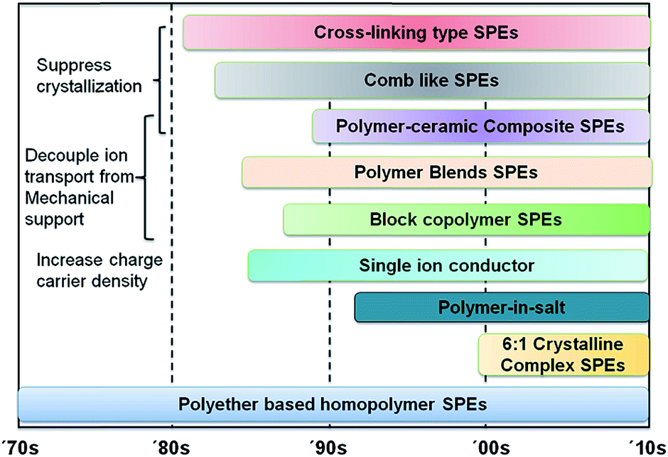 | ||
| Fig. 1 Summary of solid polymer electrolyte development during the last four decades. | ||
A number of excellent reviews have been published recently discussing various types of SPE for electrochemical device applications.1–13,25–28 In this article, we will discuss the correlation between SPE morphology and ion transport. Specifically, we will focus on anisotropic ion transport according to morphological anisotropy. We will first discuss ion transport in polymers, followed by five different types of morphological controls in SPE: crystalline structure, block copolymers, mechanically induced orientation, hybrids/nanocomposites, and holographic polymerization.
2. Ion transport in SPE
In general, there are three types of mechanisms governing ionic charge transport. First, in liquid electrolytes, solvent molecules are mobile and can form complexes with the ions, and the entire complex traverse together under external fields. Second, in solids such as β-alumina, ions reside in potential wells. Sufficient activation can induce displacement of bare ions while the other components of the lattices are strictly immobile. Third, in polymer electrolytes, since polymer chains are entangled, it's more difficult for the complexed chains to physically transport “long distance” with the associated ions as they would in a liquid system; however, above the glass transition temperature, significant chain segmental motion exists, which enables a solvation–desolvation process along the chain. When chain segmental motion allows substitution of the anion site for an additional neighboring ligand, the charged pairs are separated and move in opposite directions. To this end, in order to effectively solvate the salt and form polymer–lithium complex, the following basic criteria need to be satisfied for the host polymers: (i) a high dielectric constant (ε); (ii) high electron-donor characteristics, usually found in polymers with a high concentration of sequential polar groups on their backbone, such as ether (–O–), sulfide (–S–), amine (–N–), phosphine (–P–), carbonyl (C![[double bond, length as m-dash]](https://www.rsc.org/images/entities/char_e001.gif) O) and cyano (C
O) and cyano (C![[triple bond, length as m-dash]](https://www.rsc.org/images/entities/char_e002.gif) N), which are good candidates for complex formation;22,45 (iii) appropriate distance between coordinating centers, which is best illustrated by crown ethers;46,47 (iv) a flexible backbone and low steric hindrance for bond rotation; (v) easy to synthesize and process. PEO is one of the most extensively studied polymers for SPE because it exhibits a superior ability to form complexes with a variety of metal salts.24,45,48–50 The ethylene oxide unit (CH2CH2O) has strong electron donating capability and an optimal heteroatom spacing; both characteristics facilitate the dissociation of the salt. The high flexibility of the PEO chain, indicated by a low glass transition temperature, allows for reorganization of the chain for cation coordination. Polypropylene oxide (PPO) is another candidate as an ion-hosting polymer. Although it remains amorphous at room temperature favoring ion mobility, the solvation ability is less effective than PEO due to its low dielectric constant and steric hindrance imposed by the additional methyl groups.45,48 Other polymers, such as polysiloxanes, poly(ethylene succinate) and poly(ethylene imine), have shown a certain capacity for complex formation with alkali metal salts, but are far less studied than PEO-based polyethers.45,48
N), which are good candidates for complex formation;22,45 (iii) appropriate distance between coordinating centers, which is best illustrated by crown ethers;46,47 (iv) a flexible backbone and low steric hindrance for bond rotation; (v) easy to synthesize and process. PEO is one of the most extensively studied polymers for SPE because it exhibits a superior ability to form complexes with a variety of metal salts.24,45,48–50 The ethylene oxide unit (CH2CH2O) has strong electron donating capability and an optimal heteroatom spacing; both characteristics facilitate the dissociation of the salt. The high flexibility of the PEO chain, indicated by a low glass transition temperature, allows for reorganization of the chain for cation coordination. Polypropylene oxide (PPO) is another candidate as an ion-hosting polymer. Although it remains amorphous at room temperature favoring ion mobility, the solvation ability is less effective than PEO due to its low dielectric constant and steric hindrance imposed by the additional methyl groups.45,48 Other polymers, such as polysiloxanes, poly(ethylene succinate) and poly(ethylene imine), have shown a certain capacity for complex formation with alkali metal salts, but are far less studied than PEO-based polyethers.45,48
Only salts with a low lattice energy have been demonstrated to form complexes with a given polymer host.45 These salts are usually characteristic of large anions with negative charges well dispersed by the electron withdrawing ligands. The higher the degree of charge delocalization, the better the solvation of the salt is in a given host. The dissociation constant for commonly used anions follows the order below:48,49,51,52
| (CF3SO2)2N−,AsF6− > PF6− > ClO4− > BF4− > CF3SO3− > CF3CO2− |
Other factors that need to be taken into consideration for the salt to be used as the solute in the electrolyte include: high solubility and conductivity, inert against electrodes, wide electrochemical window, good thermal stability, and minimum toxicity. Summaries on the property and performance of different types of salts can be found in several reviews.25,51,53
As previously mentioned, one of the greatest challenges for SPE development is to improve the room temperature conductivity to at least 10−4 S cm−1 while maintaining the shear modulus of the electrolyte sufficiently high (∼7 GPa suggested by computational simulation54) to inhibit lithium dendrite formation. During the last few decades, tremendous efforts have been made to develop novel SPE systems that can meet the desired performance requirement; these strategies generally fall into the following three scenarios: (i) designing of a multiphase SPE to decouple ion transport from the mechanical support; (ii) improving conductivity anisotropy, optimizing ion conducting pathways by creating directional and continuous conducting channels; (iii) developing single ion conductors to increase charge carrier density. Table 1 summarizes the properties of a number of selected SPEs recently reported. The following sections will provide detailed discussions with the focus on anisotropic ion transport.
| Type of SPE | Category | Examples | σ (S cm−1) @ T (°C) | Mechanical strength (Pa) | Ref. |
|---|---|---|---|---|---|
| a Dynamic Young's modulus was measured at 1 Hz.b Shear modulus was measured using parallel plate rheometer.c Ionic conductivity was measured parallel to PEO cylinder long axis.d Ionic conductivity was measured parallel to the smectic layer.e d.c. conductivity was measured along the stretching direction using four-probe-electrode setup.f Tensile strength was measured at 40 °C on a DMA at 0.1 N min−1 ramp force.g BCP: block copolymer, LC: liquid crystalline. | |||||
| BCP SPE | (i) | PS-P(S-g-EO)-PS + LiTFSI (O/Li = 20) | 2 × 10⁻⁵ @ RT | 108a | 55 |
| PSt-b-PPME-b-PSt (80% PEO content) | ∼10−4 @ RT | 5 × 10⁶ | 56 | ||
| PS-b-PEO + LiTFSI (O/Li = 50) | ∼10−3 @ 90 | ∼108 @ 90b | 57 | ||
| LC-BCP SPE | (i), (ii) | PEO-b-PMA/CB + LiClO4 (O/Li = 120) | 2 × 10⁻⁷ @ 20c | N/A | 58 |
| 2/LiCF3SO3 | 1.5 × 10⁻⁶ @ 35d | N/A | 59 | ||
| PEO–ceramic nanofiller | (i), (iii) | PEG (Mn 250 Da)/LiTFSI (O/Li = 20) + 20 wt% fumed silica | 10−3 @ RT | 105 @ RT | 60 |
| P(EO)8LiClO4 + 10 wt% TiO2 (13 nm) | 1.75 × 10⁻⁵ @ RT | N/A | 29 | ||
| Stretched SPE | (ii) | P(EO)7LiI | ∼10−4 @ RTe | N/A | 61 |
| HP | (i), (ii) | Norland 65 + PEG(400 Da) + LiTFSI (O/Li = 19) @ 45 v/v% | 1.93 × 10⁻⁵ @ RT | N/A | 62 |
| Single ion conductor | (iii) | PCHFEM-Li/PEO (Mw 400 kDa) blend | ∼10−5 @ 100 | N/A | 63 |
| P(MEO-MALi) | 2 × 10⁻⁷ @ RT | N/A | 64 | ||
| P(STFSILi)-b-PEO-b-P(STFSILi) @ O/Li = 27 | ∼10−5 @ 60 | ∼9 × 10⁶f | 65 | ||
3. Crystalline morphology directed ion transport
3.1 Phase diagrams of PEO based SPE
It is helpful to start our discussion with a phase diagram of a SPE. Taking PEO as an example, the phase behavior and crystalline morphology of PEO–lithium salt SPEs have been extensively studied since 1980s.19,20,66–72 Several phases are defined in a PEO–lithium salt SPE: a crystalline PEO phase, amorphous PEO–lithium complex phase, and stoichiometric crystalline PEO–lithium complex phases. The number and types of phases depend on the anions, salt concentration and thermal history, and can be determined by X-ray diffraction, NMR, thermal analysis or polarized light microscopy (PLM).66 We define three regions of semicrystalline SPE based on the type of phases present in the electrolyte at room temperature. Dilute electrolytes (typically at an O/Li molar ratio less than 20) consist of two phases: a crystalline PEO phase and an amorphous PEO–lithium complex phase. Semi-dilute electrolytes (an O/Li molar ratio of approximately 8–20) have the most complicated morphology where multiple phases co-exist, including crystalline PEO, an amorphous PEO–lithium complex phase and a crystalline PEO–lithium complex phase. A concentrated SPE (or polymer in salt) consists of crystalline complexes with stoichiometry of 6:1, 4:1, 3:1 or 2:1 depending on the type of anion. Semi-dilute and concentrated regions are of practical importance since that is where the optimal ionic conductivity is often observed.
Fig. 2 shows the reported phase diagrams of a few commonly studied PEO–lithium salt SPEs.66,73 Stoichiometric compounds of 6:1 and 3:1 are found in the SPEs containing LiClO4, LiAsF6 and LiN(CF3SO2)2 (LiTFSI), while only a PEO–lithium 3:1 complex is identified in PEO–LiCF3SO3 SPEs. A eutectic point with a melting temperature of 50–55 °C is observed for all types of SPEs at a composition range ∼10 < O/Li molar ratio < 100 except for low Mw PEO–LiTFSI SPE, in which a crystallinity gap between 6 < O/Li < 12 is observed due to the plasticizing effect of the anion. P(EO)6LiAsF6 has a melting temperature of 136 °C, which is 70 °C higher than that of P(EO)6LiClO4. Most P(EO)3LiX complexes have melting temperatures above 100 °C.
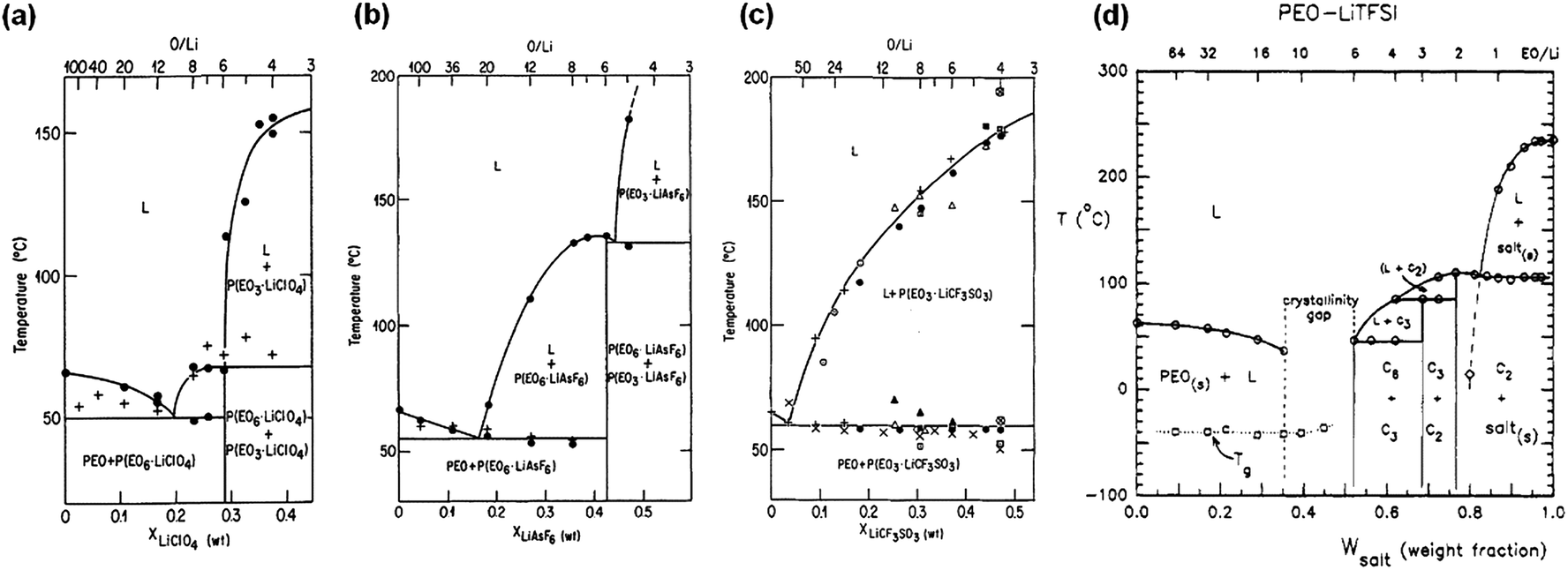 | ||
| Fig. 2 Phase diagrams of a series of PEO–LiX electrolytes: (a) PEO–LiClO4; (b) PEO–LiAsF6; (c) PEO–LiCF3SO3; (d) PEO–LiTFSI. (a–c) are reprinted with permission from J. Electrochem. Soc., 133(2), 315–325, (1986). Copyright© 1986, The Electrochemical Society; (d) is reprinted with permission from Macromolecules, 1994, 27, 7469–7477. Copyright© (1994) American Chemical Society. | ||
The ionic conductivity, σ, can be correlated to the concentration of free ions, or ions contributing to charge flow, p, and the diffusion coefficient, D, with the Nernst–Einstein relationship, eqn (1):
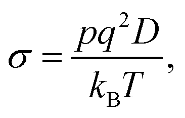 | (1) |
The overall conductivity of the polymer electrolytes is determined by (i) the number of charge carriers; (ii) degree of charge dissociation, and (iii) the interaction between the ions and the polymer chain, all of which are strongly affected by the ion concentration. For most of the SPE systems above the PEO melting temperature, the optimized ionic conductivity is achieved at an O/Li molar ratio of 8–20, as shown in Fig. 3. In the dilute region, the ionic conductivity increases monotonically with ion concentration due to the increased number of charge carriers. Above the optimal concentration, ionic conductivity begins to decrease as a result of significant ion pairing and physical cross-linking between polymer chains and Li+ ions, and from the formation of PEO–Li crystalline complex that restricts the ion mobility. At temperatures below Tm, the concentration dependence on ionic conductivity is complicated by PEO crystallization.
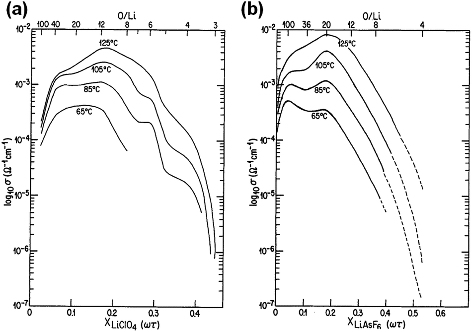 | ||
| Fig. 3 Ionic conductivity as a function of salt content at various temperatures for (a) PEO–LiClO4 system; (b) PEO–LiAsF6 system. Reprinted with permission from J. Electrochem. Soc., 133(2), 315–325 (1986). Copyright© 1986, The Electrochemical Society. | ||
3.2 Ion conduction in crystalline SPE complex
At high concentrations, PEO forms stoichiometric crystalline compounds with Li+ cations. These crystalline compounds are generally believed to be insulating except for certain P(EO)6:LiXF6 crystalline complexes (X = P, As, Sb) that were reported by Bruce et al.32,74,75 The structure of this 6:1 crystalline electrolyte was resolved from powder diffraction data; one example (P(EO)6:LiAsF6 crystalline complex) is shown in Fig. 4a.32,74–77 The crystalline complex adopts a monoclinic unit cell with two PEO chains interlocking to form cylinders and Li+ cations residing in a row inside each of the cylinders. Each PEO chain adopts a non-helix conformation of ctgḡtgcḡtcttgtḡcgt. The anions are located between the cylinders and do not coordinate with Li+. The crystalline structures of all three complexes are similar, and the Li+ coordination number and Li–O bond strength remain unchanged for all three crystalline complexes. As the anion size increases from PF6− to AsF6− to SbF6−, the volume of the unit cell expands by pushing the cylinders apart along b and c axis and stretching the polymer chain along a axis.
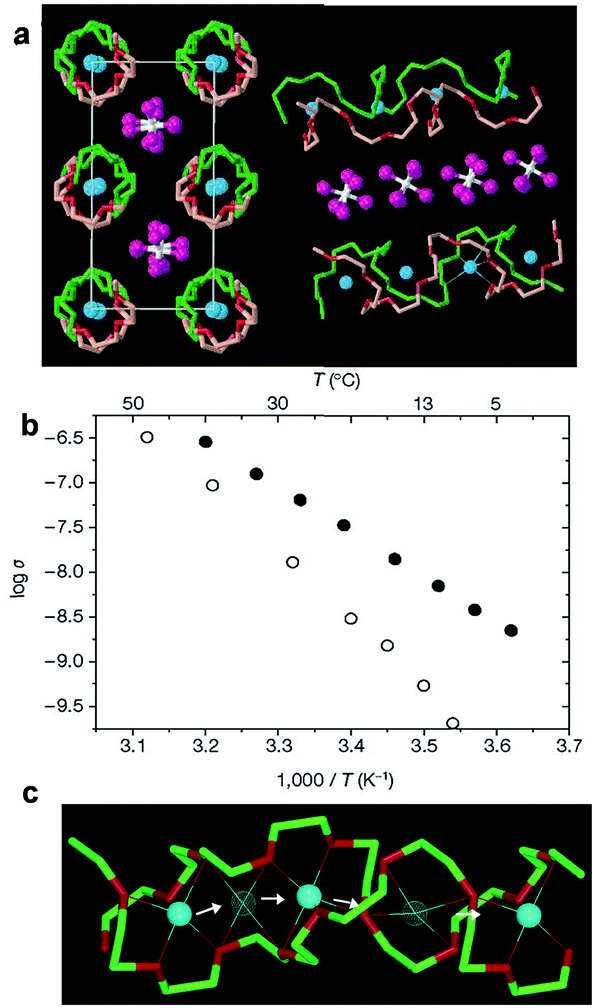 | ||
| Fig. 4 (a) Crystal structure of P(EO)6:LiAsF6 crystalline complex; (b) temperature dependent ionic conductivity of crystalline (solid circle) and amorphous (open circle) P(EO)6:LiSbF6; (c) schematic illustration of Li+ diffusion pathways in a P(EO)6LiPF6 crystalline complex. (a and b) are reprinted by permission from Macmillan Publishers Ltd, Nature, 2001, 412, 520–523, Copyright© (2001). (c) is reprinted with permission from J. Am. Chem. Soc., 2003, 125, 4619–4626. Copyright© (2003) American Chemical Society. | ||
The temperature dependent ionic conductivity of crystalline P(EO)6:LiSbF6 as shown in Fig. 4b suggests that ion conduction not only takes place in crystalline phases, but also is faster compared with that in more mobile amorphous phases. The conductivity plot of P(EO)6:LiSbF6 exhibits typical Arrhenius behavior, indicating an ion hopping mechanism is dominating for the ion conduction. The Li+ diffusion pathway within the cylinder is also proposed based on the crystal structure and is illustrated in Fig. 4c. The migration of Li+ from one site to the neighboring site is facilitated by the presence of vacancy defects.
Despite that promising ion conduction has been demonstrated in these P(EO)6:LiXF6 crystalline complexes, the room temperature conductivities (10−7 to 10−8 S cm−1) are still not sufficient for lithium battery applications. Substituting LiXF6 with a salt-bearing large delocalized anion, such as TFSI−, improves the conductivity by one to two orders of magnitude due to the disruption of the potential around Li+ in the region of TFSI− anion.34 Increasing the PEO polydispersity or replacing the methoxy capped chain end with –OC2H5 group may further improve the conductivity by one order of magnitude via introducing more defects that lead to an increased concentration of charge carriers.78 Another limitation for using these crystalline SPEs is that the optimal ionic conductivity is at Mw of 1000 Da, relatively small for practical applications; further increasing the Mw significantly reduces ion conductivity due to the increase of grain boundaries and misalignment of the crystallites that impedes ion transport.
3.3 Ion conduction in semi-crystalline SPE
As previously discussed, the crystallization of linear PEO has long been viewed as unfavorable for ion conduction. PLM experiments reveal that PEO crystallizes into fringed spherulites in dilute SPE, due to the strong interference with lithium salts.79–81 During the PEO crystallization process, lithium salts are expelled from the crystals and are enriched in the amorphous phase between adjacent spherulites, as well as in the amorphous inter-lamellar region. The inhomogeneity of the SPE can be probed using impedance spectroscopy.82 In semi-dilute electrolytes, both the PEO–lithium complex (salt-rich) and the PEO (salt-poor) phases crystallize into spherulitic morphology.67,69 The salt-rich crystalline complexes also exhibit a regularly and densely packed spherulitic morphology but with higher melting temperatures.19,20,83 In addition to inter-spherulite boundaries, individual spherulites are comprised of crystalline lamellae and amorphous regions, with typical thickness of a few nm. This rather complex morphology certainly affects the macroscopic conductivity of the corresponding SPE, and in many cases, leads to conductivity anisotropy.Generally speaking, the impact of crystallization can be categorized into three aspects: (i) decreasing the effective fraction of amorphous conducting phase; (ii) restricting chain mobility (dynamic/tethered chain effect) and (iii) introducing tortuous pathways for ion transport (tortuosity effect). Although extensive studies have been conducted to understand the correlation between crystallization and ionic conductivity reduction, obtaining quantitative analysis is challenging since those three factors are usually intertwined. The temperature dependent conductivity plots of semicrystalline PEO SPEs provide some useful information on the degree of conductivity reduction due to PEO crystallization. Fig. 5 shows the conductivity plots of a series of P(EO)nLiClO4 electrolytes. A conductivity “knee” is observed for electrolytes at all concentrations around the PEO melting temperature, Tm (∼60 to 70 °C), below which the conductivity quickly drops to below 10−7 S cm−1. This 2–3 orders of magnitude of conductivity reduction at room temperature results from the decrease of the conducting phase volume fraction, restriction of chain mobility, and the increased tortuosity as mentioned earlier, whereas the contributions from each factor cannot be quantitatively deconvoluted. All SPEs follow a typical Arrhenius behavior below the Tm of PEO, suggesting that the long range polymer segmental motion is restricted and ion hopping is the major ion conducting mechanism. The steeper slope at low temperatures indicates that there is a higher energy barrier for ion transport in semicrystalline SPEs.
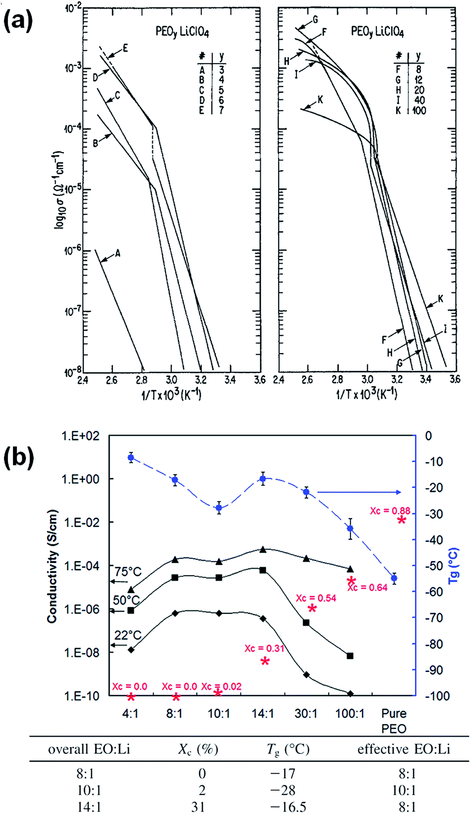 | ||
| Fig. 5 (a) Temperature dependent ionic conductivity for solution cast P(EO)nLiClO4 electrolytes, reprinted with permission from J. Electrochem. Soc., 133(2), 315–325 (1986). Copyright© 1986, The Electrochemical Society (b) ionic conductivities, glass transition temperatures (Tg) and crystallinity (*) as a function of LiClO4 concentration at different temperatures for PEO–LiClO4 SPE, adapted with permission from Macromolecules, 2009, 42, 2142–2156. Copyright© (2009) American Chemical Society. | ||
Although the highest ionic conductivity is expected to be in the completely amorphous state where the chain mobility is higher, an interesting observation has been reported by Fullerton-Shirey et al. on solution cast PEO–LiClO4 SPE systems.84 The plot in Fig. 5b shows that the 14:1 (O/Li molar ratio) sample with 31% crystallinity has comparable and even higher ionic conductivity than the 8:1 sample that is completely amorphous at 22 °C and 50 °C, respectively, though the effective Li+ concentration (normalized by PEO crystallinity) and the Tg of the two SPE are the same. Apparently in this case, the ion conduction is decoupled from chain mobility and the enhanced ionic conductivity in semicrystalline SPE indicates that there might be a faster ion transport in the amorphous conducting phase when confined by the PEO crystalline lamellae.
3.4 Ion conduction in polymer single crystal SPE
We recently demonstrated that in addition to the well-known slowed dynamics of the tethered amorphous chain, the tortuous ion diffusion pathway associated with 2D polymer lamellar crystals is critical to the overall observed conductivity reduction. We quantitatively deconvoluted these two factors by preparing a model system (a SPE comprised of polymer single crystals and lithium salts, denoted as polymer single crystal SPE) with precisely controlled crystalline morphology and crystal orientation.85 Polymer single crystals have been used for a variety of applications, and polymer single crystal SPEs are one of the most recent developments.86–103 To prepare the SPEs with precisely controlled morphology, PEO single crystals were first grown in dilute pentyl acetate solution using a self-seeding method.86–90 Because of the well-controlled crystallization conditions, the obtained PEO single crystals have a uniform size: they are approximately ∼20 × 20 μm wide (Fig. 6a) and ∼10 nm thick, and therefore can be viewed as quasi-2D nanoplates. The single crystal suspension was slowly casted onto a PTFE substrate and dried under vacuum at room temperature to yield a single crystal film with an average thickness of ∼20 μm (Fig. 6c). 2D WAXD experiments were conducted with the X-ray beam parallel to the film surface, and the in-plane diffraction pattern reveals well oriented patterns with (120) equatorial diffractions at 2θ = 19.15° and (032) diffraction at 2θ = 23.3° in the quadrants. Detailed analysis of the pattern shows that the polymer chains are aligned parallel to the film's normal and the Herman's orientation factor of (120) diffraction, f120, is calculated to be 0.80. The period of the lamellar stacks is 9.6 nm, which is comprised of two layers of amorphous loops attached to the crystalline stems. The crystallinity Xc is estimated to be 0.77 based on the integrations of isotropic WAXD patterns. Combining SAXS and WAXD results, the thickness of each amorphous loop layer is calculated to be approximately 1.1 nm, and the crystalline stems have a thickness of 7.4 nm.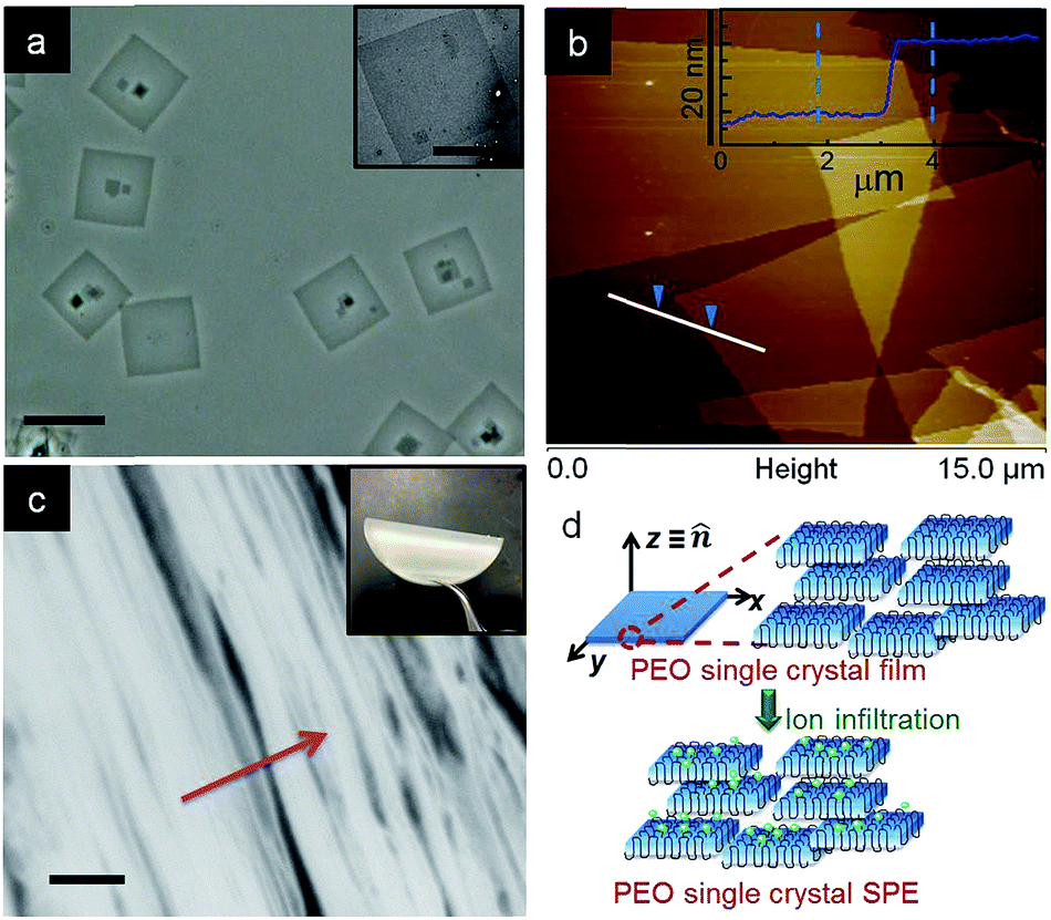 | ||
| Fig. 6 (a) Phase contrast optical microscopy image of PEO single crystals grown from dilute solution before casting into films (scale bar is 20 μm). Inset shows a transmission electron micrograph of a typical single crystal (scale bar is 10 μm); (b) atomic force microscopy height image of a 15 × 15 μm area scan of PEO single crystals. Inset shows the corresponding height profile along the white line; (c) scanning electron micrograph of the cross-section of a PEO single crystal film, red arrow shows the film normal (scale bar is 200 nm). Inset shows the optical image of the dry film; (d) schematic of PEO single crystal SPE preparation.85 Reprinted with permission from Macromolecules, 2014, 47, 3978–3986. Copyright© (2014) American Chemical Society. | ||
To prepare PEO single crystal SPEs, LiClO4 was infiltrated into the above mentioned PEO single crystal films by soaking the latter in a LiClO4/pentyl acetate solution at various salt concentrations and infiltrating times. To simplify the system, we controlled the Li+ concentration in the region of 0.001 < r < 0.05, where r is the molar ration between Li+ and EO group, so that only crystalline PEO and amorphous PEO–Li complex are present. SAXS and WAXD show that we can adopt a 2-phase model with a PEO crystalline phase and an amorphous PEO/Li+ salt phase to analyze the ion transport behavior: all the ions are confined in a 2D space with a thickness of ∼2–3 nm. We then used an effective Li+ to EO molar ratio by normalizing r with the corresponding crystallinity of each SPE, denoting the normalized r as 〈r〉 (〈r〉 = r/(1 − Xc)). Fig. 7 shows that both in-plane conductivity σ‖ and through-plane conductivity σ⊥ increase rapidly with 〈r〉 at low Li+ ion concentrations (〈r〉 < 0.02), and nearly plateau when 〈r〉 > 0.02. The conductivity difference along these two directions can be quantified by defining an anisotropy factor as A = σ‖/σ⊥. For 〈r〉 < 0.02, A is approximately 800–2000, and it decreases to 100–300 when 〈r〉 > 0.02. A modified Nielsen's model, which is typically used to describe the relative permeability in polymer nanocomposites containing platelet-like nanofillers, was used to explain the conductivity anisotropy:104–106
 | (2) |
cos2θ − 1〉, where θ is the angle between the platelet normal and the diffusion direction. If we treat the crystalline portion of the 2D PEO single crystals as platelet-like nanofillers and the amorphous fold regions as the matrix, eqn (2) can be used to describe the relative permeability of lithium ions (Rσ) diffusing through the single crystal SPE compared to an amorphous matrix. The anisotropy factor A = σ‖/σ⊥ = Rσ‖/Rσ⊥ was calculated to be 668 at ϕs = 0.77, and 521 at ϕs = 0.6. The calculated value fits well with the measured anisotropy at the lower r region but is slightly higher than the measured value at the higher r region. This discrepancy may be because Nielsen's model is usually used to describe non-interacting gas molecules diffusing through a composite system and is only valid when the molecule size is much smaller than the nanofiller dimension.
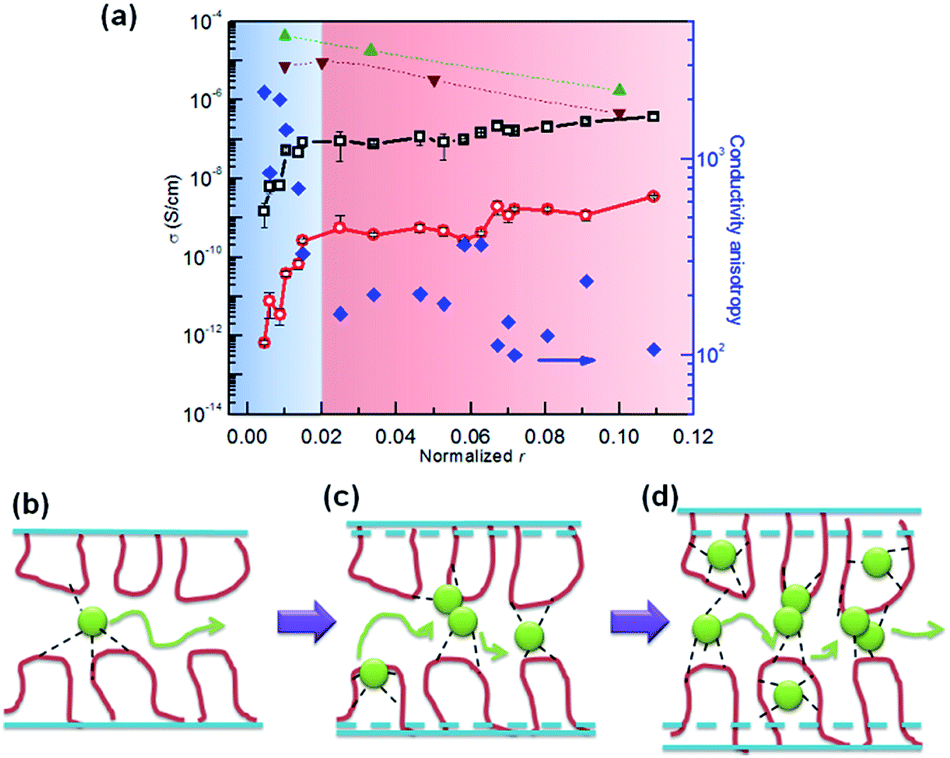 | ||
| Fig. 7 (a) Ionic conductivity and conductivity anisotropy at RT as a function of normalized r (black open square – σ‖ of single crystal SPE; red open circle – σ⊥ of single crystal SPE; blue solid diamond – conductivity anisotropy σ‖/σ⊥ of single crystal SPE; green triangle – σ0 of linear PEO–LiClO4 SPE; brown inverted triangle – σ0 of network PEO–LiClO4 SPE from ref. 107) (b–d) shows that ions are confined in the PEO fold regions at different concentrations.85 Reprinted with permission from Macromolecules, 2014, 47, 3978–3986. Copyright© (2014) American Chemical Society. | ||
Fig. 7 also shows the differences between σ‖ and isotropic amorphous SPE at corresponding ion contents (σ0). At r = 0.1, σ0 can be directly measured immediately after quenching the SPE from 120 °C to room temperature because the SPE remains 100% amorphous due to the slow crystallization kinetics at this ion concentration. For linear SPE at r < 0.1, a Vogel–Tammann–Fulcher (VTF) equation was used to fit the high temperature (above melting) data and extrapolate the plot to room temperature,108–110 in order to obtain σ0 values (shown as green triangles in Fig. 7). As a comparison, σ0 values of cross-linked PEO network (100% amorphous) SPE reported by Watanabe et al.107 are also shown in Fig. 7. Despite a slight discrepancy of the σ0 values, which is likely due to cross-linking effects, the conductivities for both linear amorphous and network SPEs gradually decrease with increasing Li+ concentration, due to the increase of the glass transition temperature. In the dilute ion region, e.g. 〈r〉 = 0.01 and the effective EO to Li ratio is 100:1, there are ∼12 loops per Li+ on the crystal surface. Considering Li+ ions are confined between two fold surfaces, each Li+ ion has to hop over ∼2–3 loops, or approximately ∼1 nm, to reach another ion as depicted in Fig. 7b. It would be energetically more difficult for these tethered segments to adjust their local conformation in order to assist the multiple hopping of each ion compared with amorphous SPE. At higher salt concentrations (e.g. 〈r〉 = 0.11) where σ/// σ0 is ∼1, there is approximately one Li+ ion per loop, allowing Li+ to efficiently hop among PEO loops. The tethered chain effect seems to be overwhelmed by the cross-linking introduced by the Li+ ions themselves, and the only effect of crystallization on the overall conductivity of SPE is tortuosity. Furthermore, the molecular conformation of the loop and the typically crosslinked amorphous PEO are likely different. The loops are well defined and locally pinned between the adjacent crystalline stems, while the linear amorphous PEO, even crosslinked, may undergo long or semi-long range reptation.
3.5 Summary of crystalline structure effect on ion transport
In summary, the ion conduction in linear PEO based SPEs is complicated by crystallization. Although there is a direct correlation between polymer dynamics and ion transport in most of these SPEs, caution needs to be taken when interpreting the ionic conductivity in a specific SPE system. The segmental motion alone cannot fully explain the ion conduction phenomenon in crystalline SPE. The nanoscale structure and morphology of the electrolytes are also important factors that contribute to the overall ionic conductivity.4. Anisotropic ion transport in block copolymer SPE
4.1 Phase behavior and ion distribution in BCP SPE
Due to the unique micro-phase separated structure, block copolymer SPEs containing rigid reinforcing segment and soft ion conducting segment provide an elegant solution for decoupling of mechanical properties and ionic conductivity.27,56,57,111–119 The degree of phase separation of the block copolymer is governed by the Flory–Huggins interaction parameter (χ). Depending on the degree of polymerization (N) and the volume fraction (f) of each block, the morphology of a linear AB diblock copolymer could change from spherical (S), cylindrical (C), gyroid (G), and lamellar (L).120,121 The most commonly studied block copolymer SPEs are based on polymer/salt blends in which the salt is preferentially dissolved in the PEO block. Introduction of lithium salt into the conducting domain significantly influences the phase behavior of the block copolymer and ultimately impacts the ionic conductivity of the SPE.57,111,122–133 The shift in phase behaviors in these block copolymer SPE systems is attributed to the change of Flory–Huggins interaction parameter (χ) due to the introduction of the salt. The complexation between PEO chains and lithium ions typically results in an increased incompatibility between the PEO domain and the non-conducting domain, driving the phase separation towards the strong segregation region. On the other hand, this ordered nanostructure renders property anisotropy of block copolymer SPE.Ion distribution in block copolymer SPEs is the starting point to discussing conductivity anisotropy. Gomez et al. studied the Li+ distribution in a polystyrene-b-PEO (PS-b-PEO) block copolymer SPE with lamellar morphology using energy-filtered transmission electron microscopy.116 The elemental mapping of the block copolymer SPE cross-section reveals that lithium ions are preferentially located at the center region of the PEO domains. This is because the PEO chains are stretched at the interface and this extended conformation is unfavorable for EO/Li+ coordination, leading to an exclusion of the ions away from the PEO–PS interfacial region (Fig. 8).
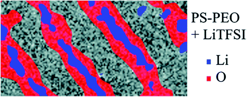 | ||
| Fig. 8 Elemental mapping of a PS–PEO block copolymer SPE doped with LiTFSI. Reprinted with permission from Nano Letters, 2009, 9, 1212–1216. Copyright© (2009) American Chemical Society. | ||
The chain stretching effect at the interface of the two blocks and uneven ion distribution suggest a fundamental difference in ion conduction mechanism between block copolymer SPE and homopolymer SPE. As discussed earlier, the ion conduction mechanism in homopolymer electrolyte systems is mainly governed by the polymer segmental motion. The cation mobility initially decreases with the increase of Mw and becomes nearly independent of Mw above the Mc (3200 g mol−1 for PEO), which is consistent with the Mw dependence on Tg. However, the ionic conductivity shows a complex dependence on the molecular weight in the block copolymer SPE case. Balsara and co-workers have systematically studied the Mw effect in a lamella-forming PEO–PS block copolymer electrolyte doped with LiTFSI.57,116,117,134 In the low Mw region where MSEO is below 10 kg mol−1, all the ions are confined in the interfacial zone, and the ion conduction is affected by at least two competing factors: Tg of the PS block and the width of the conducting PEO channel, and the net effect results in a weak linear declining trend of the normalized conductivity as a function of MSEO. When MSEO is above 10 kg mol−1, the interfacial effect becomes negligible and the normalized conductivity exhibits a sigmoidal increase with increasing Mw due to the increased fraction of the “free” PEO conducting channel. Ganesan et al. employed coarse-grained simulations of the sorption and transport of penetrant cations to study the Mw dependence of conductivity of homopolymer and block copolymer SPE.135 They showed that in homopolymer SPE, diffusivity effects associated with the free ends of the polymers play an important role. In block copolymer lamellae, the interfacial zone between the blocks presents hindered ion diffusivity and is dependent on molecular weight.
4.2 Alignment and conductivity anisotropy in BCP SPE
In addition to the altered phase behavior and nonuniform distribution of ions in the PEO domain, the nonconductive domain of the block copolymer apparently blocks ion transport, which leads to anisotropic ion transport. Gwee et al. reported anisotropic conducting behavior in a PS-b-poly(methyl methacrylate) (PS-b-PMMA)/1-ethyl-3-methylimidazolium bis (trifluoromethylsulfonyl)imide (EMIm-TFSI) blend system.136 Young et al. investigated the correlation between sample processing conditions and the corresponding ionic conductivity using LiClO4 doped PEO-b-PS, where PEO is the majority domain.137 The SPE samples were hot pressed into disks under vacuum. The authors also cut the disks into ∼0.5 mm wide strips, which were turned 180° and 90° with respect to the axial direction of each strip, and repacked. They found that for a lamella-forming sample, the moderate shear created during hot-pressing can orient domains perpendicular to the compression force direction and led to as much as 2.5 times decrease in the through-plane conductivity. However, for a hot-pressed cylinder-forming sample, conductivity was not affected by the domain orientations due to the 3-D conducting pathway of the PEO matrix.Park et al. systematically studied the alignment effect on conductivity in proton-conducting domains in hydrated poly(styrenesulfonate-b-methylbutylene) copolymer films using several approaches, including solvent casting, hot pressing, and applying external forces such as electric field, or mechanical shearing.138 The alignment of lamellae was quantified by a combination of 2D SAXS, birefringence, and TEM. Quantitative relationships between domain orientations and transport properties were obtained via in-plane and normal-to-plane proton conductivity measurements of aligned samples. They showed that the pressed sample had highly anisotropic proton conduction with A = 75. Electric field and shear flow alignment lead to an A of ∼1.3 and 1.4, respectively (Fig. 9).
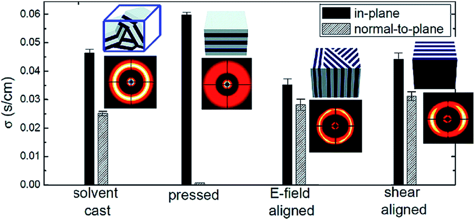 | ||
| Fig. 9 The equilibrium in-plane and normal-to-plane conductivity values of as-cast and aligned samples.138 Reprinted with permission from Macromolecules, 2009, 43, 292–298. Copyright© (2009) American Chemical Society. | ||
The conductivities in block copolymer SPEs are often estimated using the effective medium theory (EMT).139 Based on EMT, if one assumes that the ions are only located in one phase, the effective conductivity σ can be written as:
| σ = fϕcσ0 | (3) |
Liquid crystal (LC) directed block copolymer alignment appears to be a more efficient approach to enhance conductivity anisotropy.58,59,140,143–146 Kishimoto reported a macroscopically oriented LC polymeric film with a layered nanostructure prepared by in situ photopolymerization. The ethylene oxide segment was selectively doped with LiSO3CF3 for ion conduction and the mesogenic core induced the self-assembly.59 The electrolyte membrane was spontaneously aligned perpendicular to the glass or ITO substrate when cooled from the isotropic to smectic A phases, and conductivity anisotropies as high as ∼4.5 × 10³ were observed at 35 °C, indicating that the ion conduction is efficiently confined within the layer. However, the degree of alignment is limited to the micrometer scale along the thickness direction and none of the studies had compared the in-plane conductivity of the aligned SPE with the isotropic or intrinsic conductivity values.
Alignment of the micro-domains leads to an improvement of the ionic conductivity by creating continuous conducting pathways for directional ion transport. Li et al. reported an anisotropy in lithium ion conductivity in phase-segregated LC diblock copolymer PEO-b-PMA(Az) membranes containing mesogene azobenzene units, 11-[4-(4′-butylphenyl-azo)phenoxy]-undecyl methacrylate PMA(Az)144,147 and perpendicularly oriented PEO cylindrical domains as ion transport channels (Fig. 10a–c). Selective doping of lithium salts into the PEO cylindrical domains was achieved by mixing an appropriate amount of LiCF3SO3 with 4 wt% of toluene solution containing the copolymer, then coating onto the desired substrate, and annealing at 140 °C for 24 h. The microphase segregation forces the PEO cylindrical domains containing the lithium salt to be hexagonally arranged and normally oriented in the PMA(Az) domain matrix. Fig. 10d and e shows the atomic force microscopy (AFM) top and cross-sectional images of the phase separated SPE. Most of the cylinders with a diameter of around 11 nm can span the entire membrane, i.e., from one interface to the other. Fig. 10f shows the temperature dependence of the ionic conductivities perpendicular (σ⊥) and parallel (σ∥) to the substrate at two salt concentrations. At an O/Li molar ratio of 20:1, the perpendicular conductivity initially increases with the increasing temperature. Above the transition temperature from the smectic A to the isotropic phase, the perpendicular conductivity abruptly drops. The same tendency was observed at the higher salt concentration (O/Li molar ratio = 4:1), although the increase in σ⊥ conductivity was not as high as expected. On the contrary, the parallel conductivity behaves in a different manner, exhibiting a monotonous increase with increasing temperature for O/Li molar ratios of 20:1 and 4:1. The maximum anisotropy A reaches 450 and 40 for O/Li molar of 20:1 and 4:1, respectively.
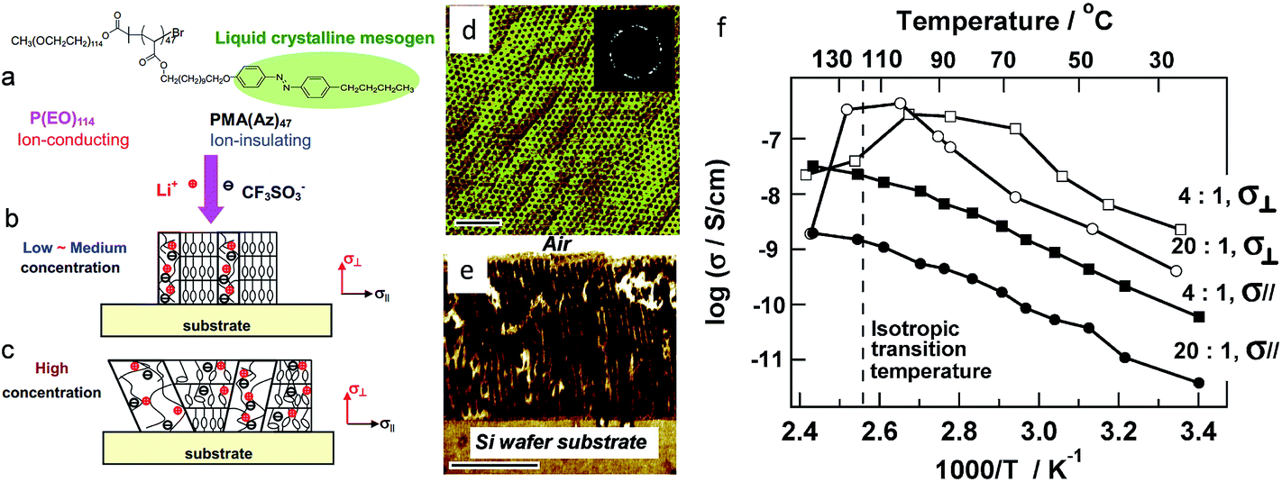 | ||
| Fig. 10 Schematic drawing of structure evolution of diblock copolymer complexes PEO114-b-PMA(Az)47 + LiCF3SO3 at low – medium and high salt concentrations. (a) Chemical structure of the block copolymer, (b) at low and medium salt concentration, selective complexation of Li+ with PEO phase leads to the formation of ordered array of ion-conducting PEO nanocylinders, which are perpendicular to the substrate surface, (c) at high salt concentration, the lithium salt dissolves in both PEO and PMA(Az)47 domains, depresses liquid crystalline ordering and disturbs phase segregation of diblock copolymer. (d and e) Top and cross-sectional AFM phase images of PEO114-b-PMA(Az)47 + LiCF3SO3 membranes (EO:Li+ = 20). (f) Corresponding conductivity. Adapted with permission from Macromolecules, 2007, 40, 8125–8128. Copyright© (2007) American Chemical Society. | ||
Osuji and co-workers reported macroscopic alignment of LC-block copolymer SPE using magnetic fields.58,140,145,146,148–150 Fig. 11 shows an example of the structure of a poly(ethylene oxide-b-6-(4′-cyanobiphenyl-4-yloxy)-hexyl methacrylate) PEO-b-PMA/CB block copolymer membrane. LiClO4 was selectively doped into the PEO cylindrical domains for ion conduction and the alignment of PEO cylinders was directed by the smectic poly(MA/CB) block upon magnetic field exposure.
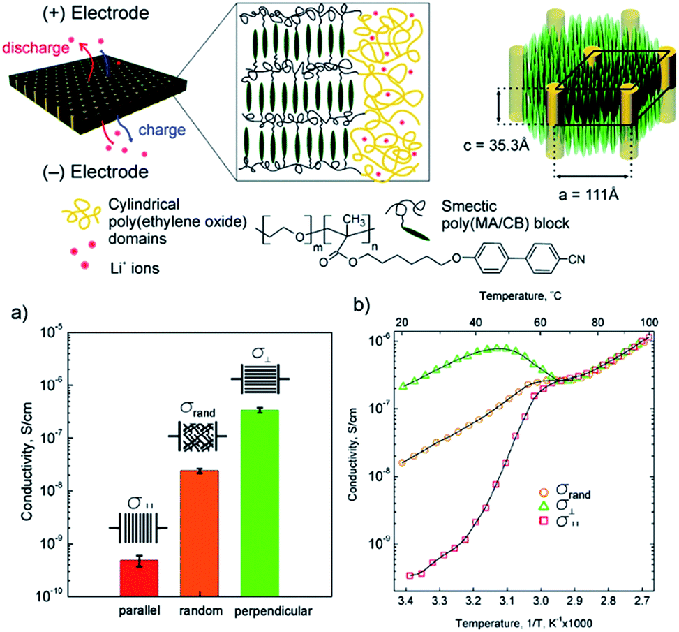 | ||
| Fig. 11 Structure of the poly(ethylene oxide-b-6-(4′-cyanobiphenyl-4-yloxy)-hexyl methacrylate) PEO-b-PMA/CB block copolymer membrane doped with LiClO4 (top); (a) room temperature ionic conductivities and (b) temperature dependent conductivity plots of random and aligned block copolymer SPE along two orthogonal directions.58 Reprinted with permission from J. Am. Chem. Soc., 2010, 132, 17516–17522. Copyright© (2010) American Chemical Society. | ||
In this work, the parallel (‖) and perpendicular (⊥) directions were defined as the PEO cylinders parallel and orthogonal to the electrode surface, respectively. The conductivity anisotropy A reached ∼103 under 5 T magnetic field, suggesting the effective blocking of ion migration transverse to the PEO cylinder long axis direction. Interestingly, a nearly 10-fold increase of the σ⊥ compared with that of isotropic SPE was observed, which deviated from the expected 2-fold increase based on the morphological argument predicted by EMT. This discrepancy suggests that the less ideal connectivity at the grain boundaries may have caused the conductivity decrease in the isotropic LC block copolymer SPE.
5. Mechanical field induced anisotropic ion transport
Conductivity anisotropy has also been found in stretched semi-crystalline PEO SPEs.61,151–158 Golodnitsky and co-workers reported stretching induced conductivity enhancement by a factor of 5 to 40 in several P(EO)nLiX (X = I, CF3SO3, TFSI, BOB) electrolytes.61,151–153,158 In these studies, the hot pressed electrolyte membranes were uniaxially stretched under 450–500 N cm−2 load at elevated temperatures and the in situ longitudinal conductivity was monitored. Stretching induces the unraveling of loops in the polymer molecules and enhances the chain alignment along the direction of applied force. Despite a decrease of polymer segmental motion, it was suggested that Li+ hopping along the helix is facilitated by the long range order, as supported by the enhanced Li+ diffusivity measured by Li NMR and the decreased activation energy obtained from Arrhenius plot. A maximum conductivity anisotropy of 40 was observed in a concentrated semi-crystalline electrolyte P(EO)7LiI, in which the partial alignment of the PEO helices in the crystalline phase was believed to be responsible for the conductivity enhancement.Li et al. used multi-axis pulsed-field-gradient NMR to measure diffusion anisotropy to probe the orientational order as a function of water content and membrane stretching in a uniaxially stretched Nafion film.159 They showed that transport anisotropy depends linearly on the degree of alignment: with increased alignment, substantial enhancement in water transport along the draw direction and suppression in the transverse direction was achieved. Dong et al. fabricated Nafion nanofibers using electrospinning and showed that a high proton conductivity value of 1.5 S cm−1 was achieved. X-ray scattering showed oriented ionic domains in the nanofiber, which account for the enhanced ion conductivity.160
6. Anisotropic ion transport in hybrids/nanocomposite SPE
6.1. SPE containing low dimensional particles
Another widely studied approach to address both conductivity and mechanical properties is based on PEO–ceramic nanocomposite SPEs. The incorporation of certain ceramic fillers with Lewis acid characteristic such as TiO2, SiO2, or Al2O3 has been shown to enhance both ionic conductivity and mechanical properties of the SPE.26,29–31,60,161–176 During the early investigations, Scrosati and co-workers showed that the addition of micro-sized ceramic particles γ-LiAlO2 into a P(EO)8LiClO4 SPE improved the mechanical properties, interfacial stability and ionic conductivity;161 however, the mechanism of this enhancement was not well understood. Follow-up studies suggest that ceramic particles with nanoscale particle sizes can result in even better performance, and the ion conduction mechanism in these nanocomposite SPE was systematically studied.29–31,165,167,170 It was suggested that the ceramic nanoparticles with Lewis acid characteristics are competing with lithium cations to form complexes with PEO. Hanson et al. suggested that the ion mobilities are correlated to the nanoparticle-induced changes in the polymer segmental dynamics.177 On the other hand, Chung et al. reported that the cation transference number t+ for their nanocomposite SPE (0.5–0.6 for SPE containing TiO2) was considerably higher than their ceramic-free SPE (usually 0.2–0.3), and the cation diffusivity measured by NMR methods was nearly one order of magnitude higher in the nanocomposite SPE.31 These evidences likely suggest that the specific Lewis acid–base interactions among the ceramic surface groups, lithium salt, and the polymer segments facilitate the ion dissociation and possibly create preferential conducting pathways at the boundaries of the ceramic particles, promoting Li+ transport.The types of functional groups on the surface of the ceramic particles play a critical role to the ion conduction in nanocomposite SPEs. In a study conducted by Croce et al., three types of Al2O3 nanoparticles with acidic, neutral and basic surface characteristics were incorporated into a P(EO)20LiSO3CF3 SPE.170 The acidic and neutral Al2O3 based SPEs showed higher degrees of conductivity enhancement over the basic Al2O3 SPE, leading the author to propose the mechanism to be the specific Lewis-acid interactions. Acidic/neutral Al2O3 forms hydrogen bonding with the anions as well as the ether oxygens on PEO chains, promoting the salt dissociation and weakening the cation-polymer coordination, while the basic Al2O3 can only interact with Li+; however, the study conducted by Jayathilaka et al. on a P(EO)9LiTFSI SPE system suggests that there is no direct interaction between the filler particles and the polymer chain. The Al2O3 particles interact with both cations and anions, providing additional sites for ion hopping. In this case, the degree of conductivity improvement provided by the nanoparticles followed the order: acidic > basic > neutral > weakly acidic > filler free.171 Another study on a low Mw PEG–LiClO4–Al2O3 system showed that the neutral fillers gave higher conductivity compared with acidic and basic fillers.168 There is no clear trend of surface group type versus conductivity enhancement, and it seems the specific interactions also depend on the type of anions and the polymer matrix being used.
Although the nanocomposite approach for novel SPE development appears to be promising, the conductivity enhancement due to the nanoparticles is not universal and contradictory results have been found in other SPEs. Best et al. found no improvement, and even a decrease of conductivity in some fully amorphous polyether based SPEs with the addition of TiO2 or Al2O3 nanoparticles.178 Johansson et al. reported no significant influence of the SiO2 fillers on amorphous PEO–LiTFSI SPEs.179 Xie et al. studied a PEO–LiTFSI SPE containing fumed silica nanoparticles, and conductivity of the composite SPE was found to be decreased above Tm when compared with an ultrapure PEO SPE.180 Depending on the type of anions, the nature of the nanoparticles and the structure and molecular weight of the polymer, different ion conduction mechanisms may be present.
Besides the multi-phase nanocomposite SPE, a few mono-phase hybrid SPEs have also been studied, including 3D hybrid inorganic organic network SPE and Zeolitic inorganic–organic SPE.181–186 In these systems either metal, non-metal atoms or inorganic clusters are bridged by organic molecules to form ion-conducting materials. Detailed reviews on those systems can be found elsewhere.187,188
6.2 Two-dimensional nanoplatelets induced conductivity anisotropy
While the effect of 0-dimensional (0D) nanoparticles on the ionic conductivity of the SPE is still under debate, it is evident that introducing 2-dimensional (2D) nanoplates can induce conductivity anisotropy in the resultant SPE systems. Montmorillonite and hectorite, as charged layer (2D) silicates, have been compounded with polymer ion hosts using solution infiltration, melt blending and layer-by-layer (LbL) assembly methods to fabricated hybrid SPE. For PEO/montmorillonite composites, Ruiz-Hitzky et al. demonstrated conductivity enhancement in the hybrid SPE, and attributed this enhancement to increased layer separation, a factor associated with relaxations of the polymer chain.189,190 It was suggested that the polymer weakens the interactions between the cation and the negatively charged clay surface, thereby increasing conductivity. A conductivity anisotropy of approximately 100 for polyphosphazene–montmorillonite SPE was reported by Hutchison et al.191 Lutkenhaus et al. used an LbL method to fabricate hybrid SPE comprised of poly(ethylene imine) (PEI), LAPONITE® clay, and PEO (Fig. 12).192 What was unique in their system is that PEI/Li-clay/PEO forms trilayers; each trilayer was approximately 5 nm thick, and clay platelets were controlled to be parallel with the substrate. Anisotropic ion transport, resulting from the anisotropic structure, was demonstrated with a conductivity anisotropic factor of ∼100. They also showed that the activation energy associated with ion transport in (PEI/Li-clay/PEO) (0.35–0.37 eV) was similar to that of lithium cations in PEO.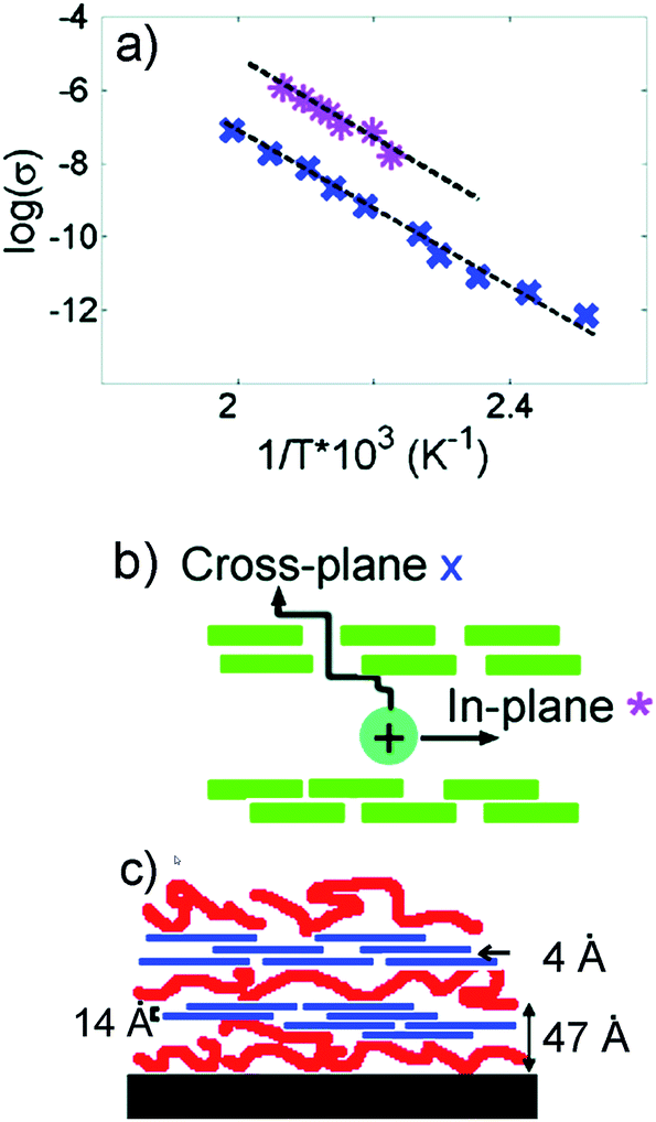 | ||
| Fig. 12 (a) Arrhenius plot of the variation of conductivity with temperature. In-plane conductivity (pink *) is ∼100 times higher than cross-plane conductivity (blue x). (b) Schematics showing that cross-plane ion conduction is hindered by the presence of ordered clay nanoplatelets. (c) Proposed structure of PEI/Li-clay/PEO LbL assembly. The trilayer thickness is 4.7 nm, basal spacing 1.4 nm, and gallery spacing 0.4 nm.192 Reprinted with permission from Langmuir, 2007, 23, 8515–8521. Copyright© (2007) American Chemical Society. | ||
7. Holographic polymerization
Holographic polymerization (HP) has been used to fabricate tunable periodic nanostructured membranes with long-range order and low defect content.193 Recently it has been demonstrated that this versatile technique can be used to fabricate novel electrolyte membranes with both robust mechanical properties and highly ordered conducting channels. During the photopolymerization process, a mixture of photopolymerizable monomers, initiator, and inert components are exposed to an interference pattern generated by two or more coherent beams. The monomers diffuse into the light, or constructive region, and start to cross-link, while all the inert components are partitioned into the dark, destructive interference volumes. Depending on the geometry of the optical setups, 1D, 2D or 3D nanostructure with tunable spacing can be readily patterned. HP structures can be used in various exciting applications.194,195 Due to incorporation of inert materials, a diversity of polymer composite systems can be fabricated in a top-down manner with unprecedented structural control. Introduction of soft matter, such as LCs as the inert material, leads to the formation of holographic polymer dispersed liquid crystals whose band gap can be tuned by electric fields and mechanical strain.195 Hierarchically ordered gratings have also been achieved by using block copolymers as the inert materials.144,196–198 Using HP, we recently demonstrated fabrication of long range ordered ∼100 nm nano-channels of electrolyte comprised of Norland 65, PEO and bis trifluoromethanesulfonimide lithium salt (LiTFSI) at a Li:EO ratio of 1:19, and termed the membranes holographic polymer electrolyte membranes (hPEMs).62 The volume fraction of electrolyte was varied from 29 to 55 v/v%, and a variety of morphologies were observed. At lower electrolyte loadings, ∼50–200 nm droplets were formed in well-confined 1D layers. Droplet growth, coalescence and deformation from photopolymer impingement within these layers as the electrolyte loading was increased up to 45–50 v/v% were observed in TEM, shown in Fig. 13. Upon further loading of the electrolyte, the thermodynamics of the system limited the formation ability of the grating, and an ordered assembly of electrolyte droplets is barely evident in the TEM images.
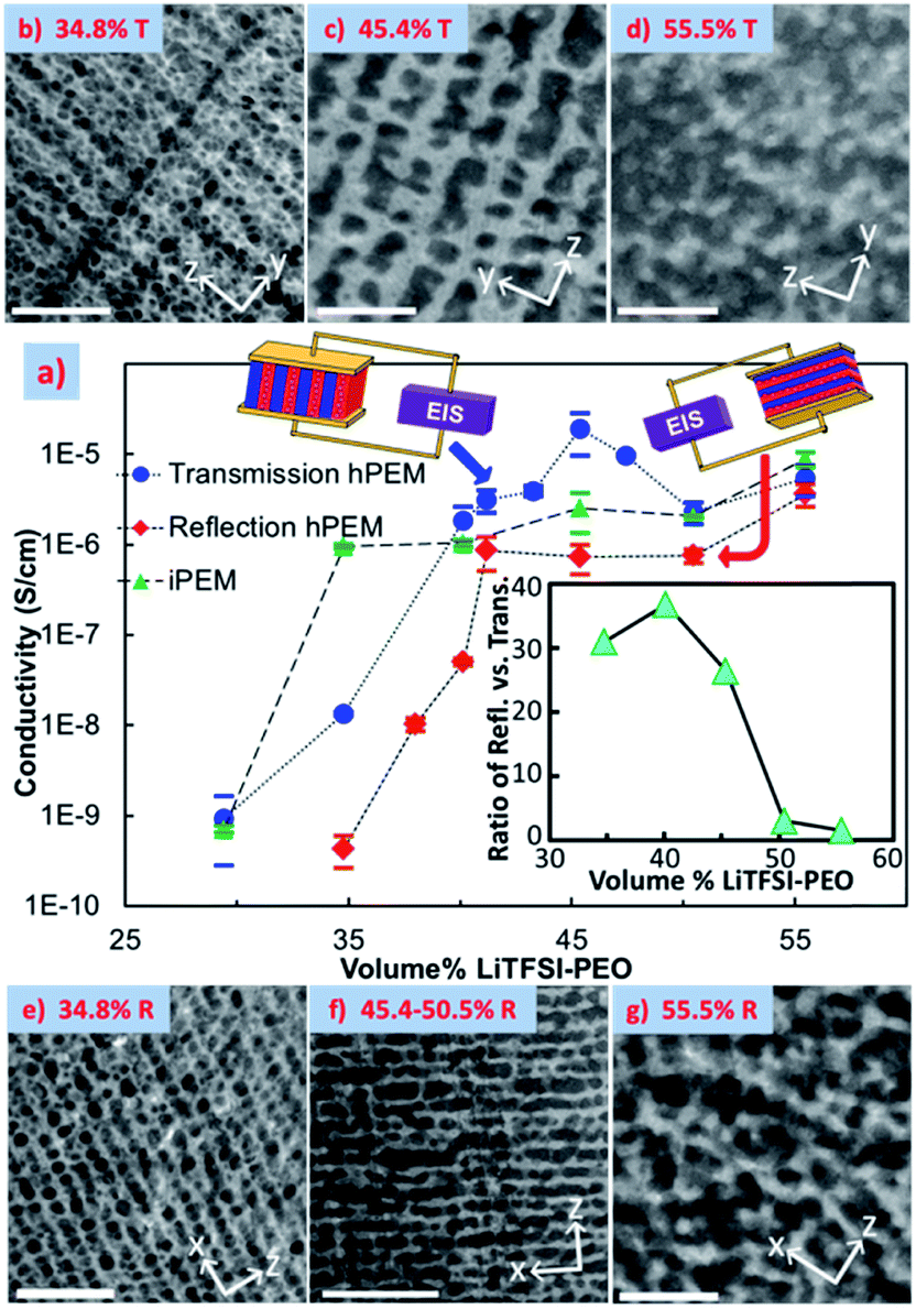 | ||
| Fig. 13 EIS conductivity with respect to electrolyte v/v% loading measured in the films' z direction (a) and TEM images of corresponding transmission gratings (b–d) and reflection gratings (e–g) with corresponding electrolyte v/v% with scale bars of 1 μm.62 Reprinted with permission from Nano letters, 2011, 12, 310–314. Copyright© (2011) American Chemical Society. | ||
Electrochemical impedance spectroscopy (EIS) was used to determine the ionic conductivity of the films at room temperature, shown in Fig. 13. Both through- and in-plane measurements displayed a percolation-like behavior that increased the conductivity by ∼3 orders of magnitude. The in-plane conductivities were consistently higher than the reflection gratings', and a maximum anisotropy of 38 was achieved, which was a 3-fold improvement over one-step thin film synthesis techniques at time of publication. This consistent anisotropic behavior is clear evidence for effective ion-confinement and channel formation.
However, while already a 3-fold improvement over one-step thin film synthesis techniques, much available improvement exists by optimizing the morphology beyond a semi-continuous brick-and-mortar structure. In HP, the final morphology can be controlled by tuning the phase separation and photopolymerization kinetics. To this end, we used trihexyltetradecylphosphonium bromide (BrTHTDP) ionic liquid (IL) to replace the PEO/LiTFSI system.199 Fig. 14 shows TEM images of various electrolyte loadings, where the dark domains are IL-rich regions and the lighter domains are cross-linked NOA65. Phase separated, defect free, and long-range continuous layers for both the IL and NOA65 can be seen clearly in all the samples. “Cross talk” of adjacent layers was not observed for either domain in any film characterized. Normalized conductivities for in-plane and through-plane directions, and the resulting ionic conductivity anisotropy versus electrolyte loading, are also shown in Fig. 14. σ∥ varies moderately with increasing IL concentration and a maximum normalized conductivity is seen at 40 w/w% with 6.24 × 10⁻⁶ S cm−1, which is comparable to the pure IL conductivity of 5.28 × 10⁻⁶ S cm−1. Increasing or decreasing the IL loading from this ratio decreases the normalized conductivity, suggesting optimal partitioning at this loading. σ⊥ is lower than σ∥ for all the hPEMs; it significantly rises with electrolyte loading, and experiences a weak percolation-like behavior at 45 w/w% loading. As a result, the anisotropy increases to 5120 at 30 w/w% and then decreases to ∼20 for 45 w/w% hPEM. Clearly, the relatively clean phase separation also results in the extremely high conductivity anisotropy between the in-plane and through-plane directions; the homogeneous NOA65-rich layer “blocks” the through-plane ion transport. This control is governed by two factors: the concentration of ions in the NOA-rich layer, and the decrease of ion mobility caused by an increase in viscosity, which hinders ion flux. As the NOA65 monomer loading is decreased, the thickness of the NOA-rich layer decreases and the volume fraction of trapped ions increases. At a certain NOA-layer thickness and ion volume fraction, the ions are able to percolate through the depth of the NOA65 blockade.
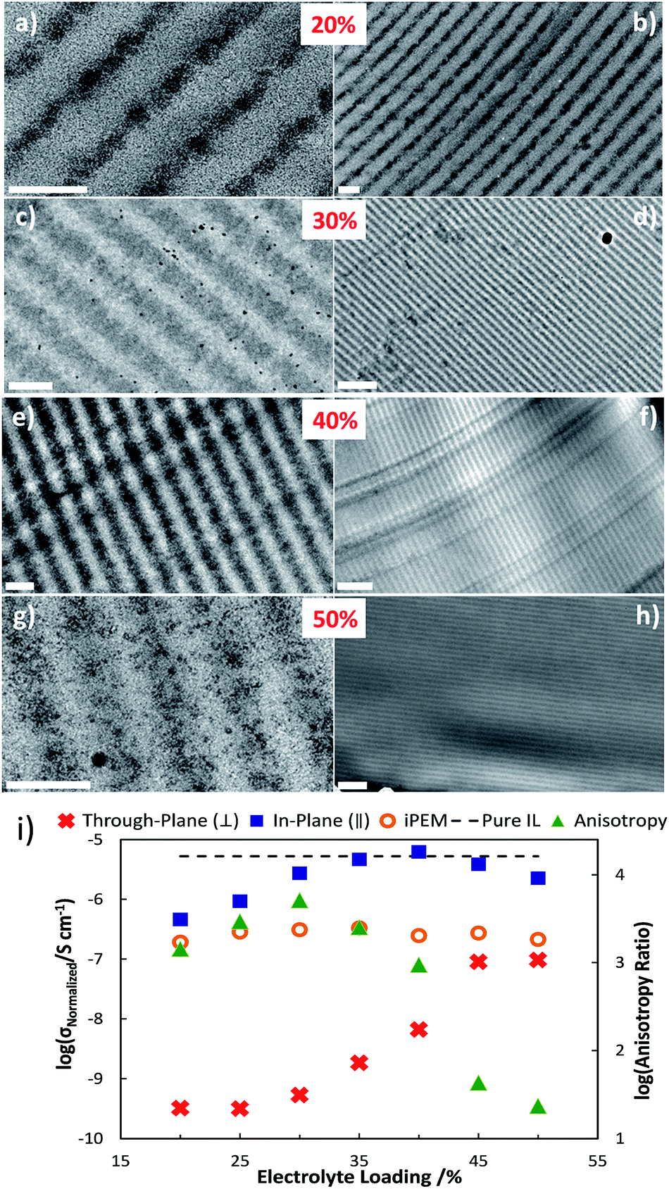 | ||
| Fig. 14 TEM images of hPEMs. (a), (c), (e), and (g) Micrographs of 20–50 w/w% electrolyte with a scale bar of 200 nm. (b), (d), (f), and (h) Micrographs with a scale bar of 1 μm. All samples were ultra-microtomed stained with RuO4. (i) Ionic conductivity measured via EIS normalized by IL volume fraction versus electrolyte content of hPEMs for parallel (blue squares), perpendicular (red crosses) and isotropically polymerized membranes (orange circles) at room temperature. Anisotropic ratio of in-plane versus through-plane is shown in green triangles. Error bars are on the same scale as the symbols. Reprinted from J. Pow. Sour., 2014, 271, 597–603. Copyright© (2014), with permission from Elsevier. | ||
8. Summary and outlook
In this article, we briefly summarized the anisotropic ion transport in five types of SPE, namely semicrystalline, block copolymer, mechanically stretched, hybrids/nanocomposites, and holographic polymerized SPEs. Such anisotropy typically arises from nanoscale morphology and plays a significant role in SPE performance. Despite four decades of extensive work in SPEs, the detailed structures and dynamic nature of ion containing SPEs are still not clear; the intertwined structural and dynamic effects of polymer chains on ion transport and the altered phase behaviors of polymers upon ion doping all factor into the complex behavior of SPEs. From a scientific point of view, it is intriguing to investigate the phase structures and dynamics of these complex SPEs. From a technological standpoint, one has to be mindful of both the potential and limitations in the reported systems. For each system, there are challenges and opportunities.8.1 Semicrystalline SPE
Our discussion showed that crystalline lamellae in semicrystalline SPE confine and direct ion transports. Therefore, anisotropic crystalline morphology can be correlated directly with anisotropic ion transport. In order to design SPEs for practical applications, high through-plane ion conduction is needed, which dictates the lamellae must be perpendicular to the polymer electrolyte membrane. External fields or epitaxy growth may be employed for this particular purpose.8.2 Block copolymer SPE
Block copolymer SPEs have been widely studied. The nonconducting domain of the block copolymer can be used to direct ion transport. Well aligned block copolymer nanomorphology leads to highly anisotropic ion conduction, and mitigates the domain contact effect that could reduce ion conductivity. The next challenge is achieving large scale aligned block copolymers in an energetically economical manner.8.3 Mechanical fields
Mechanical fields can induce conductivity anisotropy and can be implemented easily based on today's industry setting, though the conductivity anisotropy is relatively small compared with other methods. More importantly, however, using this method leads to the faster ion transport direction being perpendicular to the film, which is orthogonal to the preferred transport direction for most applications.8.4 Hybrids/nanocomposites
Incorporating inorganic fillers to fabricate hybrid/nanocomposite SPE has shown promise in both mechanical property and ion conductivity enhancement. Although there are debates on detailed mechanisms, using 2D or 1D nanofillers to guide ion transport in SPEs is an interesting direction to pursue. Given the variety of nanofillers available, it is anticipated that research activities in the direction will grow further.8.5 Holographic polymerized SPE
Holographic polymerized SPEs are a relatively new approach; nevertheless, unprecedented ion transport anisotropy has been demonstrated. Considering defect-free nanostructure can be fabricated within a fraction of minutes, this novel system might lead to a library of interesting SPEs. The clearest challenge in this direction is how to scale up the nanomanufacturing process to generate large scale membranes.It is promising for achieving high through-plane room temperature conductivity while maintaining good mechanical properties by tuning SPE nanomorphologies in systems such as block copolymer, nanoparticle containing, and holographic polymerized SPE. While ion conductivity, phase structure, and mechanical properties of SPEs have been extensively studied, more battery testing experiments need to be conducted to validate the end device performance.
Acknowledgements
CYL is grateful for the support from the National Science Foundation over the years through grants CMMI-1100166, EEC 1138240, CMMI-1200385, CMMI-1334067, DMR-1308958, and CBET 1438240. DMS would like to acknowledge the NSF IGERT and GRFP fellowship support.References
- J. M. Tarascon and M. Armand, Nature, 2001, 414, 359–367 CrossRef CAS PubMed.
- M. Armand and J. M. Tarascon, Nature, 2008, 451, 652–657 CrossRef CAS PubMed.
- I. Stepniak and E. Andrzejewska, Electrochim. Acta, 2009, 54, 5660–5665 CrossRef CAS PubMed.
- A. M. Stephan, Eur. Polym. J., 2006, 42, 21–42 CrossRef PubMed.
- J. Y. Song, Y. Y. Wang and C. C. Wan, J. Power Sources, 1999, 77, 183–197 CrossRef CAS.
- E. Quartarone and P. Mustarelli, Chem. Soc. Rev., 2011, 40, 2525–2540 RSC.
- A. Lewandowski and A. Swiderska-Mocek, J. Power Sources, 2009, 194, 601–609 CrossRef CAS PubMed.
- J. Le Bideau, L. Viau and A. Vioux, Chem. Soc. Rev., 2011, 40, 907–925 RSC.
- M. A. Hickner, Mater. Today, 2010, 13, 34–41 CrossRef CAS.
- M. B. Herath, S. E. Creager, R. V. Rajagopal, O. E. Geiculescu and D. D. DesMarteau, Electrochim. Acta, 2009, 54, 5877–5883 CrossRef CAS PubMed.
- J. B. Goodenough and Y. Kim, Chem. Mater., 2010, 22, 587–603 CrossRef CAS.
- P. G. Bruce, B. Scrosati and J. M. Tarascon, Angew. Chem., Int. Ed., 2008, 47, 2930–2946 CrossRef CAS PubMed.
- D. T. Hallinan Jr and N. P. Balsara, Annu. Rev. Mater. Res., 2013, 43, 503–525 CrossRef.
- D. E. Fenton, J. M. Parker and P. V. Wright, Polymer, 1973, 14, 589 CrossRef CAS.
- P. V. Wright, Br. Polym. J., 1975, 7, 319–327 CrossRef CAS PubMed.
- P. V. Wright, J. Polym. Sci., Polym. Phys. Ed., 1976, 14, 955–957 CrossRef CAS PubMed.
- A. Killis, J.-F. Le Nest and H. Cheradame, Makromol. Chem. Rapid. Comm., 1980, 1, 595–598 CrossRef CAS PubMed.
- C. C. Lee and P. V. Wright, Polymer, 1982, 23, 681–689 CrossRef CAS.
- D. R. Payne and P. V. Wright, Polymer, 1982, 23, 690–693 CrossRef CAS.
- C. Berthier, W. Gorecki, M. Minier, M. B. Armand, J. M. Chabagno and P. Rigaud, Solid State Ionics, 1983, 11, 91–95 CrossRef CAS.
- K. Murata, S. Izuchi and Y. Yoshihisa, Electrochim. Acta, 2000, 45, 1501–1508 CrossRef CAS.
- W. H. Meyer, Adv. Mater., 1998, 10, 439–448 CrossRef CAS.
- S. Takeoka, H. Ohno and E. Tsuchida, Polym. Adv. Technol., 1993, 4, 53–73 CrossRef CAS PubMed.
- M. A. Ratner and D. F. Shriver, Chem. Rev., 1988, 88, 109–124 CrossRef CAS.
- E. Quartarone and P. Mustarelli, Chem. Soc. Rev., 2011, 40, 2525–2540 RSC.
- E. Quartarone, P. Mustarelli and A. Magistris, Solid State Ionics, 1998, 110, 1–14 CrossRef CAS.
- W. S. Young, W. F. Kuan and T. H. Epps, J. Polym. Sci., Part B: Polym. Phys., 2014, 52, 1–16 CrossRef CAS PubMed.
- Y. A. Elabd and M. A. Hickner, Macromolecules, 2011, 44, 1–11 CrossRef CAS.
- F. Croce, G. B. Appetecchi, L. Persi and B. Scrosati, Nature, 1998, 394, 456–458 CrossRef CAS.
- F. Croce, L. Persi, F. Ronci and B. Scrosati, Solid State Ionics, 2000, 135, 47–52 CrossRef CAS.
- S. Chung, Y. Wang, L. Persi, F. Croce, S. Greenbaum, B. Scrosati and E. Plichta, J. Power Sources, 2001, 97, 644–648 CrossRef.
- Z. Gadjourova, Y. G. Andreev, D. P. Tunstall and P. G. Bruce, Nature, 2001, 412, 520–523 CrossRef CAS PubMed.
- Z. Stoeva, I. Martin-Litas, E. Staunton, Y. G. Andreev and P. G. Bruce, J. Am. Chem. Soc., 2003, 125, 4619–4626 CrossRef CAS PubMed.
- A. M. Christie, S. J. Lilley, E. Staunton, Y. G. Andreev and P. G. Bruce, Nature, 2005, 433, 50–53 CrossRef CAS PubMed.
- A. L. Agapov and A. P. Sokolov, Macromolecules, 2011, 44, 4410–4414 CrossRef CAS.
- Y. Wang, A. L. Agapov, F. Fan, K. Hong, X. Yu, J. Mays and A. P. Sokolov, Phys. Rev. Lett., 2012, 108, 088303 CrossRef.
- K. Sinha and J. K. Maranas, Macromolecules, 2011, 44, 5381–5391 CrossRef CAS.
- K. Sinha, W. Wang, K. I. Winey and J. K. Maranas, Macromolecules, 2012, 45, 4354–4362 CrossRef CAS.
- G. J. Tudryn, W. Liu, S.-W. Wang and R. H. Colby, Macromolecules, 2011, 44, 3572–3582 CrossRef CAS.
- K.-J. Lin, K. Li and J. K. Maranas, RSC Adv., 2013, 3, 1564–1571 RSC.
- S. Dou, S. Zhang, R. J. Klein, J. Runt and R. H. Colby, Chem. Mater., 2006, 18, 4288–4295 CrossRef CAS.
- W. Wang, G. J. Tudryn, R. H. Colby and K. I. Winey, J. Am. Chem. Soc., 2011, 133, 10826–10831 CrossRef CAS PubMed.
- D. Fragiadakis, S. Dou, R. H. Colby and J. Runt, J. Chem. Phys., 2009, 130, 064907 CrossRef PubMed.
- K.-J. Lin and J. K. Maranas, Macromolecules, 2012, 45, 6230–6240 CrossRef CAS.
- M. B. Armand, Annu. Rev. Mater. Sci., 1986, 16, 245–261 CrossRef CAS.
- Crown ethers and analogs, ed., F. Vögtle and E. Weber, Wiley, New York, 1989, ch. 4 Search PubMed.
- C. J. Pedersen, Angew. Chem., Int. Ed. Engl., 1988, 27, 1021–1027 CrossRef PubMed.
- M. Armand, Solid State Ionics, 1983, 9–10(part 2), 745–754 CrossRef CAS.
- D. Baril, C. Michot and M. Armand, Solid State Ionics, 1997, 94, 35–47 CrossRef CAS.
- M. Armand, Adv. Mater., 1990, 2, 278–286 CrossRef CAS PubMed.
- K. Xu, Chem. Rev., 2004, 104, 4303–4418 CrossRef CAS.
- M. Ue, J. Electrochem. Soc., 1994, 141, 3336–3342 CrossRef CAS PubMed.
- M. Park, X. Zhang, M. Chung, G. B. Less and A. M. Sastry, J. Power Sources, 2010, 195, 7904–7929 CrossRef CAS PubMed.
- C. Monroe and J. Newman, J. Electrochem. Soc., 2005, 152, A396–A404 CrossRef CAS PubMed.
- C. Wang, T. Sakai, O. Watanabe, K. Hirahara and T. Nakanishi, J. Electrochem. Soc., 2003, 150, A1166–A1170 CrossRef CAS PubMed.
- T. Niitani, M. Shimada, K. Kawamura and K. Kanamura, J. Power Sources, 2005, 146, 386–390 CrossRef CAS PubMed.
- M. Singh, O. Odusanya, G. M. Wilmes, H. B. Eitouni, E. D. Gomez, A. J. Patel, V. L. Chen, M. J. Park, P. Fragouli, H. Iatrou, N. Hadjichristidis, D. Cookson and N. P. Balsara, Macromolecules, 2007, 40, 4578–4585 CrossRef CAS.
- P. W. Majewski, M. Gopinadhan, W.-S. Jang, J. L. Lutkenhaus and C. O. Osuji, J. Am. Chem. Soc., 2010, 132, 17516–17522 CrossRef CAS PubMed.
- K. Kishimoto, M. Yoshio, T. Mukai, M. Yoshizawa, H. Ohno and T. Kato, J. Am. Chem. Soc., 2003, 125, 3196–3197 CrossRef CAS PubMed.
- H. J. Walls, J. Zhou, J. A. Yerian, P. S. Fedkiw, S. A. Khan, M. K. Stowe and G. L. Baker, J. Power Sources, 2000, 89, 156–162 CrossRef CAS.
- D. Golodnitsky, E. Livshits, A. Ulus, Z. Barkay, I. Lapides, E. Peled, S. H. Chung and S. Greenbaum, J. Phys. Chem. A, 2001, 105, 10098–10106 CrossRef CAS.
- D. M. Smith, B. Dong, R. W. Marron, M. J. Birnkrant, Y. A. Elabd, L. V. Natarajan, V. P. Tondiglia, T. J. Bunning and C. Y. Li, Nano Lett., 2011, 12, 310–314 CrossRef PubMed.
- D. J. Bannister, G. R. Davies, I. M. Ward and J. E. McIntyre, Polymer, 1984, 25, 1291–1296 CrossRef CAS.
- N. Kobayashi, M. Uchiyama and E. Tsuchida, Solid State Ionics, 1985, 17, 307–311 CrossRef CAS.
- R. Bouchet, S. Maria, R. Meziane, A. Aboulaich, L. Lienafa, J.-P. Bonnet, T. N. T. Phan, D. Bertin, D. Gigmes, D. Devaux, R. Denoyel and M. Armand, Nat. Mater., 2013, 12, 452–457 CrossRef CAS PubMed.
- C. D. Robitaille and D. Fauteux, J. Electrochem. Soc., 1986, 133, 315–325 CrossRef CAS PubMed.
- R. Neat, M. Glasse, R. Linford and A. Hooper, Solid State Ionics, 1986, 18–19(part 2), 1088–1092 CrossRef CAS.
- M. Marzantowicz, J. R. Dygas, F. Krok, A. Łasińska, Z. Florjańczyk, E. Zygadło-Monikowska and A. Affek, Electrochim. Acta, 2005, 50, 3969–3977 CrossRef CAS PubMed.
- M. Marzantowicz, J. R. Dygas, F. Krok, J. L. Nowiński, A. Tomaszewska, Z. Florjańczyk and E. Zygadło-Monikowska, J. Power Sources, 2006, 159, 420–430 CrossRef CAS PubMed.
- M. Marzantowicz, J. R. Dygas, F. Krok, Z. Florjańczyk and E. Zygadło-Monikowska, Electrochim. Acta, 2007, 53, 1518–1526 CrossRef CAS PubMed.
- M. Marzantowicz, F. Krok, J. R. Dygas, Z. Florjańczyk and E. Zygadło-Monikowska, Solid State Ionics, 2008, 179, 1670–1678 CrossRef CAS PubMed.
- G. Zardalidis, E. Ioannou, S. Pispas and G. Floudas, Macromolecules, 2013, 46, 2705–2714 CrossRef CAS.
- S. Lascaud, M. Perrier, A. Vallee, S. Besner, J. Prud'homme and M. Armand, Macromolecules, 1994, 27, 7469–7477 CrossRef CAS.
- G. S. MacGlashan, Y. G. Andreev and P. G. Bruce, Nature, 1999, 398, 792–794 CrossRef CAS.
- Z. Stoeva, I. Martin-Litas, E. Staunton, Y. G. Andreev and P. G. Bruce, J. Am. Chem. Soc., 2003, 125, 4619–4626 CrossRef CAS PubMed.
- Z. Gadjourova, D. Martín y Marero, K. H. Andersen, Y. G. Andreev and P. G. Bruce, Chem. Mater., 2001, 13, 1282–1285 CrossRef CAS.
- G. S. MacGlashan, Y. G. Andreev and P. G. Bruce, Nature, 1999, 398, 792–794 CrossRef CAS.
- E. Staunton, Y. G. Andreev and P. G. Bruce, Faraday Discuss., 2007, 134, 143–156 RSC.
- B.-K. Choi and Y.-W. Kim, Electrochim. Acta, 2004, 49, 2307–2313 CrossRef CAS PubMed.
- M. Marzantowicz, J. R. Dygas, F. Krok, A. Łasińska, Z. Florjańczyk and E. Zygadło-Monikowska, Electrochim. Acta, 2006, 51, 1713–1727 CrossRef CAS PubMed.
- Y. Zhang, J. Li, H. Huo and S. Jiang, J. Appl. Polym. Sci., 2012, 123, 1935–1943 CrossRef CAS PubMed.
- J. R. Dygas, B. Misztal-Faraj, Z. Florjańczyk, F. Krok, M. Marzantowicz and E. Zygadło-Monikowska, Solid State Ionics, 2003, 157, 249–256 CrossRef CAS.
- M. Minier, C. Berthier and W. Gorecki, J. Phys., 1984, 45, 739–744 CAS.
- S. K. Fullerton-Shirey and J. K. Maranas, Macromolecules, 2009, 42, 2142–2156 CrossRef CAS.
- S. Cheng, D. M. Smith and C. Y. Li, Macromolecules, 2014, 47, 3978–3986 CrossRef CAS.
- D. Blundell, A. Keller and A. Kovacs, J. Polym. Sci., Part B: Polym. Lett., 1966, 4, 481–486 CrossRef CAS PubMed.
- B. Li and C. Y. Li, J. Am. Chem. Soc., 2007, 129, 12–13 CrossRef CAS PubMed.
- B. B. Wang, B. Li, B. Zhao and C. Y. Li, J. Am. Chem. Soc., 2008, 130, 11594–11595 CrossRef CAS PubMed.
- C. Y. Li, J. Polym. Sci., Part B: Polym. Phys., 2009, 47, 2436–2440 CrossRef CAS PubMed.
- P. Geil, Polymer single crystal, Interscience, New York, 1963 Search PubMed.
- B. B. Wang, B. Li, R. C. M. Ferrier and C. Y. Li, Macromol. Rapid Commun., 2010, 31, 169–175 CAS.
- B. B. Wang, B. Li, B. Dong, B. Zhao and C. Y. Li, Macromolecules, 2010, 43, 9234–9238 CrossRef CAS.
- B. Li, B. B. Wang, R. C. M. Ferrier and C. Y. Li, Macromolecules, 2009, 42, 9394–9399 CrossRef CAS.
- L. Li, C. Y. Li and C. Y. Ni, J. Am. Chem. Soc., 2006, 128, 1692–1699 CrossRef CAS PubMed.
- C. Y. Li, L. Li, W. Cai, S. L. Kodjie and K. K. Tenneti, Adv. Mater., 2005, 17, 1198–1202 CrossRef CAS PubMed.
- T. Zhou, B. Dong, H. Qi, S. Mei and C. Y. Li, J. Polym. Sci., Part B: Polym. Phys., 2014, 52, 1620–1640 CrossRef CAS PubMed.
- W. Wang and C. Y. Li, ACS Macro Lett., 2014, 3, 175–179 CrossRef CAS.
- H. Qi, W. Wang and C. Y. Li, ACS Macro Lett., 2014, 3, 675–678 CrossRef CAS.
- E. D. Laird and C. Y. Li, Macromolecules, 2013, 46, 2877–2891 CrossRef CAS.
- B. Dong, T. Zhou, H. Zhang and C. Y. Li, ACS Nano, 2013, 7, 5192–5198 CrossRef CAS PubMed.
- B. Dong, W. Wang, D. L. Miller and C. Y. Li, J. Mater. Chem., 2012, 22, 15526–15529 RSC.
- B. Dong, D. L. Miller and C. Y. Li, J. Phys. Chem. Lett., 2012, 3, 1346–1350 CrossRef CAS.
- B. Dong, B. Li and C. Y. Li, J. Mater. Chem., 2011, 21, 13155–13158 RSC.
- L. E. Nielsen, J. Macromol. Sci., Chem., 1967, 1, 929–942 CrossRef CAS PubMed.
- R. K. Bharadwaj, Macromolecules, 2001, 34, 9189–9192 CrossRef CAS.
- B. Xu, Q. Zheng, Y. Song and Y. Shangguan, Polymer, 2006, 47, 2904–2910 CrossRef CAS PubMed.
- M. Watanabe, S. Nagano, K. Sanui and N. Ogata, Polym. J., 1986, 18, 809–817 CrossRef CAS.
- H. Vogel, Phys. Z., 1921, 22, 645 CAS.
- G. Tammann and W. Hesse, J. Polym. Sci., 1926, 156, 245–257 Search PubMed.
- G. S. Fulcher, J. Am. Ceram. Soc., 1925, 8, 339–355 CrossRef CAS PubMed.
- A.-V. G. Ruzette, P. P. Soo, D. R. Sadoway and A. M. Mayes, J. Electrochem. Soc., 2001, 148, A537–A543 CrossRef CAS PubMed.
- F. M. Gray, J. R. MacCallum, C. A. Vincent and J. R. M. Giles, Macromolecules, 1988, 21, 392–397 CrossRef CAS.
- P. P. Soo, B. Huang, Y.-I. Jang, Y.-M. Chiang, D. R. Sadoway and A. M. Mayes, J. Electrochem. Soc., 1999, 146, 32–37 CrossRef CAS PubMed.
- A. A. Teran and N. P. Balsara, Macromolecules, 2011, 44, 9267–9275 CrossRef CAS.
- E. D. Gomez, M. L. Ruegg, A. M. Minor, C. Kisielowski, K. H. Downing, R. M. Glaeser and N. P. Balsara, Macromolecules, 2008, 41, 156–162 CrossRef CAS.
- E. D. Gomez, A. Panday, E. H. Feng, V. Chen, G. M. Stone, A. M. Minor, C. Kisielowski, K. H. Downing, O. Borodin, G. D. Smith and N. P. Balsara, Nano Lett., 2009, 9, 1212–1216 CrossRef CAS PubMed.
- A. Panday, S. Mullin, E. D. Gomez, N. Wanakule, V. L. Chen, A. Hexemer, J. Pople and N. P. Balsara, Macromolecules, 2009, 42, 4632–4637 CrossRef CAS.
- N. S. Wanakule, A. Panday, S. A. Mullin, E. Gann, A. Hexemer and N. P. Balsara, Macromolecules, 2009, 42, 5642–5651 CrossRef CAS.
- N. S. Wanakule, J. M. Virgili, A. A. Teran, Z.-G. Wang and N. P. Balsara, Macromolecules, 2010, 43, 8282–8289 CrossRef CAS.
- F. S. Bates and G. H. Fredrickson, Phys. Today, 1999, 52, 32–38 CrossRef CAS PubMed.
- A. J. Meuler, M. A. Hillmyer and F. S. Bates, Macromolecules, 2009, 42, 7221–7250 CrossRef CAS.
- T. H. Epps, T. S. Bailey, H. D. Pham and F. S. Bates, Chem. Mater., 2002, 14, 1706–1714 CrossRef CAS.
- B.-K. Cho, A. Jain, S. M. Gruner and U. Wiesner, Science, 2004, 305, 1598–1601 CrossRef CAS PubMed.
- W.-S. Young, P. J. Brigandi and T. H. Epps, Macromolecules, 2008, 41, 6276–6279 CrossRef CAS.
- T. H. Epps, T. S. Bailey, R. Waletzko and F. S. Bates, Macromolecules, 2003, 36, 2873–2881 CrossRef CAS.
- T. Niitani, M. Shimada, K. Kawamura, K. Dokko, Y.-H. Rho and K. Kanamura, Electrochem. Solid-State Lett., 2005, 8, A385–A388 CrossRef CAS PubMed.
- S. H. Kim, M. J. Misner, L. Yang, O. Gang, B. M. Ocko and T. P. Russell, Macromolecules, 2006, 39, 8473–8479 CrossRef CAS.
- W.-S. Young and T. H. Epps, Macromolecules, 2009, 42, 2672–2678 CrossRef CAS.
- S. N. Patel, A. E. Javier, K. M. Beers, J. A. Pople, V. Ho, R. A. Segalman and N. P. Balsara, Nano Lett., 2012, 12, 4901–4906 CrossRef CAS PubMed.
- I. Nakamura, N. P. Balsara and Z.-G. Wang, Phys. Rev. Lett., 2011, 107, 198301 CrossRef.
- I. Nakamura and Z.-G. Wang, Soft Matter, 2012, 8, 9356–9367 RSC.
- I. Gunkel and T. Thurn-Albrecht, Macromolecules, 2011, 45, 283–291 CrossRef.
- N. S. Wanakule, A. Panday, S. A. Mullin, E. Gann, A. Hexemer and N. P. Balsara, Macromolecules, 2009, 42, 5642–5651 CrossRef CAS.
- R. Yuan, A. A. Teran, I. Gurevitch, S. A. Mullin, N. S. Wanakule and N. P. Balsara, Macromolecules, 2013, 46, 914–921 CrossRef CAS.
- V. Ganesan, V. Pyramitsyn, C. Bertoni and M. Shah, ACS Macro Lett., 2012, 1, 513–518 CrossRef CAS.
- L. Gwee, J.-H. Choi, K. I. Winey and Y. A. Elabd, Polymer, 2010, 51, 5516–5524 CrossRef CAS PubMed.
- W.-S. Young and T. H. Epps, Macromolecules, 2012, 45, 4689–4697 CrossRef CAS.
- M. J. Park and N. P. Balsara, Macromolecules, 2009, 43, 292–298 CrossRef.
- J. Sax and J. M. Ottino, Polymer Engineering and Science, 1983, 23, 165–176 CAS.
- P. W. Majewski, M. Gopinadhan and C. O. Osuji, Soft Matter, 2013, 9, 7106–7116 RSC.
- L. Ramon-Gimenez, R. Storz, J. Haberl, H. Finkelmann and A. Hoffmann, Macromol. Rapid Commun., 2012, 33, 386–391 CrossRef CAS PubMed.
- M. J. Park and N. P. Balsara, Macromolecules, 2010, 43, 292–298 CrossRef CAS.
- T. Ohtake, M. Ogasawara, K. Ito-Akita, N. Nishina, S. Ujiie, H. Ohno and T. Kato, Chem. Mater., 2000, 12, 782–789 CrossRef CAS.
- M. J. Birnkrant, C. Y. Li, L. V. Natarajan, V. P. Tondiglia, R. L. Sutherland, P. F. Lloyd and T. J. Bunning, Nano Lett., 2007, 7, 3128–3133 CrossRef CAS PubMed.
- Y. Zhou, S.-K. Ahn, R. K. Lakhman, M. Gopinadhan, C. O. Osuji and R. M. Kasi, Macromolecules, 2011, 44, 3924–3934 CrossRef CAS.
- M. Gopinadhan, P. W. Majewski and C. O. Osuji, Macromolecules, 2010, 43, 3286–3293 CrossRef CAS.
- J. Li, K. Kamata, M. Komura, T. Yamada, H. Yoshida and T. Iyoda, Macromolecules, 2007, 40, 8125–8128 CrossRef CAS.
- M. Gopinadhan, P. W. Majewski, Y. Choo and C. O. Osuji, Phys. Rev. Lett., 2013, 110, 078301 CrossRef.
- M. Gopinadhan, P. W. Majewski, E. S. Beach and C. O. Osuji, ACS Macro Lett., 2011, 1, 184–189 CrossRef.
- H. Hu, M. Gopinadhan and C. O. Osuji, Soft Matter, 2014, 10, 3867–3889 RSC.
- D. Golodnitsky, E. Livshits, Y. Rosenberg, E. Peled, S. H. Chung, Y. Wang, S. Bajue and S. G. Greenbaum, J. Electroanal. Chem., 2000, 491, 203–210 CrossRef CAS.
- D. Golodnitsky, E. Livshits, Y. Rosenberg, I. Lapides and E. Peled, Solid State Ionics, 2002, 147, 265–273 CrossRef CAS.
- D. Golodnitsky, E. Livshits and E. Peled, Macromol. Symp., 2003, 203, 27–46 CrossRef CAS PubMed.
- D. Golodnitsky, E. Livshits, R. Kovarsky, E. Peled, S. H. Chung, S. Suarez and S. G. Greenbaum, Electrochem. Solid-State Lett., 2004, 7, A412–A415 CrossRef CAS PubMed.
- C. M. Burba, R. Frech and B. Grady, Electrochim. Acta, 2007, 53, 1548–1555 CrossRef CAS PubMed.
- L. Gitelman, M. Israeli, A. Averbuch, M. Nathan, Z. Schuss and D. Golodnitsky, J. Comput. Phys., 2008, 227, 8437–8447 CrossRef CAS PubMed.
- C. M. Burba, L. Woods, S. Y. Millar and J. Pallie, Electrochim. Acta, 2011, 57, 165–171 CrossRef CAS PubMed.
- D. Golodnitsky and E. Peled, Electrochim. Acta, 2000, 45, 1431–1436 CrossRef CAS.
- J. Li, J. K. Park, R. B. Moore and L. A. Madsen, Nat. Mater., 2011, 10, 507–511 CrossRef CAS PubMed.
- B. Dong, L. Gwee, D. Salas-de la Cruz, K. I. Winey and Y. A. Elabd, Nano Lett., 2010, 10, 3785–3790 CrossRef CAS PubMed.
- F. Capuano, F. Croce and B. Scrosati, J. Electrochem. Soc., 1991, 138, 1918–1922 CrossRef CAS PubMed.
- W. Krawiec, L. G. Scanlon Jr, J. P. Fellner, R. A. Vaia, S. Vasudevan and E. P. Giannelis, J. Power Sources, 1995, 54, 310–315 CrossRef CAS.
- W. Wieczorek, P. Lipka, G. Żukowska and H. Wyciślik, J. Phys. Chem. B, 1998, 102, 6968–6974 CrossRef CAS.
- C. Capiglia, P. Mustarelli, E. Quartarone, C. Tomasi and A. Magistris, Solid State Ionics, 1999, 118, 73–79 CrossRef CAS.
- F. Croce, R. Curini, A. Martinelli, L. Persi, F. Ronci, B. Scrosati and R. Caminiti, J. Phys. Chem. B, 1999, 103, 10632–10638 CrossRef CAS.
- B. Kumar and L. G. Scanlon, Solid State Ionics, 1999, 124, 239–254 CrossRef CAS.
- G. B. Appetecchi, F. Croce, L. Persi, F. Ronci and B. Scrosati, Electrochim. Acta, 2000, 45, 1481–1490 CrossRef CAS.
- M. Marcinek, A. Bac, P. Lipka, A. Zalewska, G. Żukowska, R. Borkowska and W. Wieczorek, J. Phys. Chem. B, 2000, 104, 11088–11093 CrossRef CAS.
- B. Scrosati, F. Croce and L. Persi, J. Electrochem. Soc., 2000, 147, 1718–1721 CrossRef CAS PubMed.
- F. Croce, L. Persi, B. Scrosati, F. Serraino-Fiory, E. Plichta and M. A. Hendrickson, Electrochim. Acta, 2001, 46, 2457–2461 CrossRef CAS.
- P. A. R. D. Jayathilaka, M. A. K. L. Dissanayake, I. Albinsson and B. E. Mellander, Electrochim. Acta, 2002, 47, 3257–3268 CrossRef CAS.
- W. Wieczorek, Z. Florjanczyk and J. R. Stevens, Electrochim. Acta, 1995, 40, 2251–2258 CrossRef CAS.
- M. Siekierski, W. Wieczorek and J. Przyłuski, Electrochim. Acta, 1998, 43, 1339–1342 CrossRef CAS.
- Y. W. Kim, W. Lee and B. K. Choi, Electrochim. Acta, 2000, 45, 1473–1477 CrossRef CAS.
- B.-K. Choi, Y.-W. Kim and K.-H. Shin, J. Power Sources, 1997, 68, 357–360 CrossRef CAS.
- A. S. Best, A. Ferry, D. R. MacFarlane and M. Forsyth, Solid State Ionics, 1999, 126, 269–276 CrossRef CAS.
- V. Pryamitsyn and V. Ganesan, Macromolecules, 2014, 47, 6095–6112 CrossRef CAS.
- A. S. Best, J. Adebahr, P. Jacobsson, D. R. MacFarlane and M. Forsyth, Macromolecules, 2001, 34, 4549–4555 CrossRef CAS.
- P. Johansson, M. A. Ratner and D. F. Shriver, J. Phys. Chem. B, 2001, 105, 9016–9021 CrossRef CAS.
- J. Xie, R. G. Duan, Y. Han and J. B. Kerr, Solid State Ionics, 2004, 175, 755–758 CrossRef CAS PubMed.
- L. M. Bronstein, R. L. Karlinsey, K. Ritter, C. G. Joo, B. Stein and J. W. Zwanziger, J. Mater. Chem., 2004, 14, 1812–1820 RSC.
- J. Thomas, Electrochim. Acta, 1998, 43, 1135 Search PubMed.
- M. Popall, M. Andrei, J. Kappel, J. Kron, K. Olma and B. Olsowski, Electrochim. Acta, 1998, 43, 1155–1161 CrossRef CAS.
- H.-M. Kao, T.-T. Hung and G. T. K. Fey, Macromolecules, 2007, 40, 8673–8683 CrossRef CAS.
- D. Saikia, Y.-H. Chen, Y.-C. Pan, J. Fang, L.-D. Tsai, G. T. K. Fey and H.-M. Kao, J. Mater. Chem., 2011, 21, 10542–10551 RSC.
- P. Barbosa, L. Rodrigues, M. Silva, M. Smith, A. Goncalves and E. Fortunato, J. Mater. Chem., 2010, 20, 723–730 RSC.
- V. Di Noto, E. Negro, S. Lavina and M. Vittadello, Polymer Electrolytes–Fundamentals and Applications, Woodhead Publishing Limited, Oxford, 2010, pp. 219–277 Search PubMed.
- V. Di Noto, S. Lavina, G. A. Giffin, E. Negro and B. Scrosati, Electrochim. Acta, 2011, 57, 4–13 CrossRef CAS PubMed.
- E. Ruiz-Hitzky and P. Aranda, Adv. Mater., 1990, 2, 545–547 CrossRef CAS PubMed.
- P. Aranda, J. C. Galvan, B. Casal and E. Ruiz-Hitzky, Electrochim. Acta, 1992, 37, 1573–1577 CrossRef CAS.
- J. C. Hutchison, R. Bissessur and D. F. Shriver, Chem. Mater., 1996, 8, 1597–1599 CrossRef CAS.
- J. L. Lutkenhaus, E. A. Olivetti, E. A. Verploegen, B. M. Cord, D. R. Sadoway and P. T. Hammond, Langmuir, 2007, 23, 8515–8521 CrossRef CAS PubMed.
- D. M. Smith, C. Y. Li and T. J. Bunning, J. Polym. Sci., Part B: Polym. Phys., 2014, 52, 232–250 CrossRef CAS PubMed.
- T. J. Bunning, L. V. Natarajan, V. P. Tondiglia and R. L. Sutherland, Annu. Rev. Mater. Sci., 2000, 30, 83–115 CrossRef CAS.
- C. Y. Li and T. J. Bunning, Curr. Opin. Chem. Eng., 2013, 2, 63–67 CrossRef PubMed.
- C. Y. Li, M. J. Birnkrant, L. V. Natarajan, V. P. Tondiglia, P. F. Lloyd, R. L. Sutherland and T. J. Bunning, Soft Matter, 2005, 1, 238–242 RSC.
- M. J. Birnkrant, H. K. McWilliams, C. Y. Li, L. V. Natarajan, V. P. Tondiglia, R. L. Sutherland, P. F. Lloyd and T. J. Bunning, Polymer, 2006, 47, 8147–8154 CrossRef CAS PubMed.
- M. J. Birnkrant, C. Y. Li, L. V. Natarajan, V. P. Tondiglia, R. L. Sutherland and T. J. Bunning, Soft Matter, 2011, 7, 4729–4734 RSC.
- D. M. Smith, S. Cheng, W. D. Wang, T. J. Bunning and C. Y. Li, J. Power Sources, 2014, 271, 597–603 CrossRef CAS PubMed.
Footnote |
| † Equal contribution. |
| This journal is © The Royal Society of Chemistry 2015 |