
 Open Access Article
 This Open Access Article is licensed under a Creative Commons Attribution-Non Commercial 3.0 Unported Licence
PDA@α-ZrP/SiO2 incorporated phosphate coating with enhanced corrosion resistance and friction resistance
Yuqin Tiana,
Wei Lia,
Qiaoxin Yanga,
Yuan Gonga,
Wenfei Yuea,
Yujing Oua,
Chunlei Li*a and
Xinxin Sheng *bc
*bc
aCollege of Petrochemical Technology, Lanzhou University of Technology, Lanzhou 730050, PR China. E-mail: licl@lut.edu.cn
bDepartment of Polymeric Materials and Engineering, School of Materials and Energy, Guangdong University of Technology, Guangzhou, 510006, PR China. E-mail: xinxin.sheng@gdut.edu.cn; cexxsheng@gmail.com
cGuangdong Provincial Key Laboratory of Functional Soft Condensed Matter, Guangdong University of Technology, Guangzhou 510006, PR China
First published on 6th August 2024
Abstract
In this study, α-ZrP and SiO2 composite nanomaterials were used to as phosphating accelerators. Experiments show that 2D nanosheets and 0D nanoparticles modified by PDA (PDA@α-ZrP/SiO2) play a synergistic role in effectively increasing the number of phosphate crystals and refining the crystal's size, thereby forming dense and uniform phosphate coatings. The friction resistance and corrosion resistance of phosphate coatings are simultaneously enhanced. Especially when the PDA@α-ZrP/SiO2 addition amount is 0.55 g L−1, the coating porosity of phosphate coating drops from 64.24% to 4.38%. The friction resistance coefficient drops from 0.32 to 0.02 and the polarization resistance increased from 1381 Ω cm2 to 20![[thin space (1/6-em)]](https://www.rsc.org/images/entities/char_2009.gif) 520 Ω cm2.
520 Ω cm2.
1. Introduction
Traditional phosphating technology is widely used in metal surface treatment industries, including the machinery industry, automobile industry, aviation industry and other fields.1–4 The main function of the phosphate chemical conversion coatings is to protect the base metal materials from corrosion damage. Phosphate coatings can also play a role in lubrication and friction reduction in metal cold plastic processing technology. Although traditional chemical phosphating process technology is constantly being optimized and adjusted, it cannot fundamentally solve the problems of phosphating coatings in industrial applications. Traditional high-temperature phosphating has changed to low-temperature phosphating due to problems such as acid mist and high energy consumption. However, in low-temperature phosphating, due to the low free acidity, temperature and H+ concentration, cathodic polarization is easily caused, making the phosphate coating forming reactions difficult to proceed. Therefore, a certain phosphating accelerator needs to be introduced.5,6 Traditional phosphating accelerators are mainly oxidation accelerators, including nitrite, nitrate, chlorate, etc.7,8 On the one hand, the accelerator solves the cathodic polarization process; on the other hand, it oxidizes ferrous ions into ferric ions, which effectively prevents the enrichment of ferrous ions. However, these traditional phosphating accelerators, which are currently the most widely used and effective, are carcinogenic, harmful to human health and environment. This is not in line with the concepts and trends of green production and sustainable development.9,10 Moreover, for low-temperature phosphating, improper oxidant concentration results in the generation of a large amount of phosphate sediment and contamination of the bath liquid. Phosphate sediment contains high phosphorus content and strong acidity, and is clearly classified as toxic waste. This is an urgent problem that needs to be solved in the phosphating treatment industry. An effective solution is to seek effectively and environmentally friendly green phosphate accelerators to replace traditional oxidizing accelerators.11–13The nanomaterials have received widespread research attention in phosphating technology, due to the large specific surface area and excellent physical and chemical properties. Some research works have confirmed that nanomaterials, including 2D and 0D nanomaterials, can promote the formation of phosphate coatings and have the potential to replace traditional phosphate accelerators.14,15 M. Tamilselvi et al. introduced SiO2 into the zinc phosphating baths and confirmed that SiO2 has the ability to reduce the activation energy of the phosphating process and increase the nucleation sites.16 Other works have also confirmed that nanoparticles such as nano ZnO, TiO2 and ZrO2 have the ability to promote phosphate coating formation and give phosphate coatings better performances including better corrosion resistance, coating weight, and greater substrate coverage etc.17–19 In addition to 0D nanoparticles, 2D nanosheet materials have also been proven to be used to new phosphate accelerators. Xie et al. first explored the possibility of using graphene oxide (GO) as the new environmentally friendly phosphate accelerator.14 Experimental results confirmed that in the initial stage of phosphate coating formation, the 2D GO sheets were conducive to capturing metal ions and thereby promoting the nucleation of phosphate crystals. When the number of phosphate crystals increases, the grain size is refined, which is beneficial to the formation of phosphate coatings with small porosity. At the same time, it is crucial for blocking corrosive media. Boron nitride nanosheets (BNs) has also been shown to increase the nucleation sites of phosphate crystals and thereby improve surface coverage of metal substrates.20 In our previous works, dopamine-modified MXene (MXene@PDA) played an active role in the chemical phosphating process.9 In another work, stearic acid (SA)-modified MXene not only promoted phosphating, but also imparted hydrophobic properties to phosphate coatings, further enhancing the corrosion resistance.6 Other 2D nanosheet materials such as molybdenum disulfide (MoS2), blank phosphorus, α-zirconium phosphate (α-ZrP), etc.21,22 have also been proven to have great potential as phosphate accelerators. Nanomaterials are expected to break the key bottlenecks faced by traditional phosphating.
α-ZrP, a new multifunctional 2D layered materials, is a strong solid acid with excellent ion exchange, selective adsorption and catalytic properties.23 α-ZrP exchanges with metal ions and has great dispersion stability in acid solution, which has a positive effect on promoting the process of phosphating reactions and increasing the phosphating rate.4 Polydopamine (PDA) is formed by the self-polymerization of catechol natural substance dopamine. It contains a large number of phenolic hydroxyl and amino functional groups and has strong adhesion.24 Modifying nanomaterials with PDA enhances the dispersion of nanomaterials. In addition, PDA can also adsorb metal ions such as Fe3+, Zn2+, Cu2+, etc. through surface functional groups, which also has positive effect on accelerating the phosphating process.25,26
Herein, we modified α-ZrP and SiO2 with PDA (PDA@α-ZrP/SiO2) and explored the potential of 2D/0D nanocomposites as phosphating accelerator. 2D/0D nanocomposites were designed to effectively combine the advantages of two separate components.27,28 The physicochemical properties of phosphate crystals were assessed through a series of different characterization techniques. The formation process of phosphate coatings was monitored by scanning electron microscopy (SEM). The corrosion resistance and friction resistance of the phosphate coatings were also evaluated. The results demonstrated that PDA@α-ZrP/SiO2 nanocomposite phosphate coatings presented better performances, which also imply that 2D/0D nanocomposites play a synergistic effect to achieve the more positive promotion effect on phosphating.
2. Materials and methods
2.1 Materials
All chemical reagents used were of analytical reagent. Zn(H2PO4)2·2H2O, Zn(NO3)2·6H2O and NaCl were purchased from Sinopharm Chemical Reagent Co., Ltd.Tris, SiO2 (20 ± 5 nm) and PDA were provided from Shanghai Macklin Biochemical Technology Co., Ltd. α-ZrP was produced by Fujian Runsen New Materials Co., Ltd. H3PO4 and NaOH were acquired from Guangzhou Chemical Reagent Factory. The Q235 steel samples (50 mm × 50 mm × 1 mm) with C = 0.22%, Si = 0.35%, S = 0.05%, P = 0.05%, Mn = 1.40% and Fe = balance (wt%) elemental composition were supplied from Shenzhen Oudifu Co., Ltd.
2.2 Fabrication of PDA@α-ZrP/SiO2 nanocomposite
First, 0.20 g Tris was dissolved in 200 mL water to prepare a Tris buffer solution, and then 0.20 g α-ZrP and 0.20 g SiO2 were added to the Tris buffer solution for sonication.Secondly, 0.20 g dopamine was directly added to aforementioned Tris buffer and stirred magnetically at room temperature for 24 h. Finally, after centrifugation and washing with deionized water, the PDA@α-ZrP/SiO2 was freeze-dried for subsequent use.
2.3 Fabrication of chemical conversion phosphate coatings
The metal substrates were pre-treated before phosphating. SiC-600 grits papers were used to polish and remove rust, and then 10% NaOH aqueous solution was used to degrease the metal substrate at 50 °C for 10 min. The formula of phosphating bath was based on our previous work.29 Different concentrations of PDA@α-ZrP/SiO2 (0.25 g L−1, 0.55 g L−1, 0.85 g L−1) were introduced into the phosphating bath and ultrasonicated at room temperature for 30 min to obtain the uniform phosphating solution. The pretreated Q235 substrates were placed in the prepared phosphating bath and phosphating at 50 °C for 30 min. The phosphate samples were rinsed with deionized water and dried with cold air for subsequent tests.2.4 Corrosion property test
The corrosion resistance of phosphate coatings was evaluated by EIS and potentiodynamic polarization tests, performed on the CHI-760E electrochemical workstation (Chenhua, China). A standard three-electrode system was used, with the saturated Ag/AgCl electrode, graphite electrode and phosphate coating used as the reference electrode, counter electrode and working electrode respectively. The samples were tested with 3.5 wt% NaCl solution as the electrolyte. Before EIS test, the open circuit potential (OCP) was performed for 120 s to obtain a stable OCP. And then EIS was performed at the OCP under an alternation current with an amplitude of 10 mV in the frequency range from 100 kHz to 10 mHz. The data obtained from EIS test were analyzed using ZSimpWin software (EChem Software, Q5 Ann Arbor, MI, USA) for equivalent circuit fitting. The potentiodynamic polarization curve test was performed at a scan rate of 1 mV s−1 from the cathode to anode direction (from OCP − 300 mV to OCP + 300 mV). In addition, the corrosion resistance of phosphate coatings was also evaluated through the copper sulfate drop test. All tests were performed at least three times to ensure data reproducibility.2.5 Tribological test
The tribological properties of phosphate coatings were assessed utilizing a block-on-ring wear tester (MRH-3, Jinan Yihua Tribology Testing Technology Co., Ltd, China).The tribological tests were performed for 30 min at 25 °C and 40–70% relative humidity. The rotational speed is 100 rpm and the load is 100 N for the tribological tests. The friction resistance tests were all dry friction. Each experiment was performed three times to ensure the accuracy of experimental data.
2.6 Characterizations
The microscopic morphologies of PDA@α-ZrP/SiO2 and phosphate crystals were characterized by the scanning electron microscope (SEM, Zeiss Ultra plus, Germany). Fourier transform infrared (FT-IR) and UV-vis were employed to analyze the chemical structure of 2D/0D nanocomposites. X-ray diffraction (XRD, Bruker D8 ADVANCE, Germany) was performed using a CuK radiation source to analyze the phase composition of nanocomposite and phosphate coatings. The phosphate coating thickness was measures using the coating thickness instrument (BGD 542/1 thickness meter, China). The phosphate coating weight test method refers to our previous work.43. Results and discussion
3.1 Characterization of PDA@α-ZrP/SiO2 nanocomposite
FT-IR was performed to characterize the chemical composition of SiO2, α-ZrP and PDA@α-ZrP/SiO2, and the results were shown in Fig. 1a. As to the curve of SiO2, the strong and broad absorption peak at the 1118 cm−1 position is attributed to the asymmetric stretching vibration absorption peak of Si–O–Si of SiO2. The peak around 800 cm−1 is the symmetric stretching vibration of Si–O–Si.30 The peak at 1612 cm−1 is the bending vibration peak of O–H. The character peak at 3432 cm−1 could be assigned to the stretching vibration of –OH. The characteristic bands of α-ZrP are seen at 1045 cm−1, which is attributed to the stretching vibration of P–O.31 And the peaks at 1619 cm−1 and around 3417 cm−1 are the symmetric stretching vibration peak of O–H bonds of the water molecules. In the PDA@α-ZrP/SiO2 spectrum, the peaks located at 1608 cm−1 and 1492 cm−1 are due to the C![[double bond, length as m-dash]](https://www.rsc.org/images/entities/char_e001.gif) C stretching vibration of the benzene ring of PDA. Around 1207 cm−1 is the peak of C–O–H. In addition, the characteristic peaks of SiO2 and α-ZrP coexist, which also confirms that PDA effectively modified and connected SiO2 and α-ZrP.
C stretching vibration of the benzene ring of PDA. Around 1207 cm−1 is the peak of C–O–H. In addition, the characteristic peaks of SiO2 and α-ZrP coexist, which also confirms that PDA effectively modified and connected SiO2 and α-ZrP.
 | ||
| Fig. 1 FT-IR spectra (a), XRD spectra (b) and UV-vis spectra (c) for SiO2, α-ZrP and PDA@α-ZrP/SiO2. | ||
In order to further verify that PDA successfully modified the SiO2 and α-ZrP nanocomposites, XRD was used to detect changes in phase composition (Fig. 1b). For SiO2, a broad and strong peak around 21.3° degree can be seen, which corresponds to the amorphous phase of SiO2. For α-ZrP, α-ZrP with obvious diffraction peaks has high crystallinity. The peaks at 12°, 20°, 25° and 35° respectively correspond to the (002), (110), (112) and (020) crystal planes of α-ZrP.31 When PDA was polymerized on the surface of SiO2 and α-ZrP, both the amorphous peak of SiO2 and the crystalline peak of α-ZrP can be vaguely found in PDA@α-ZrP/SiO2. It confirms that the modification of PDA effectively combined the 2D α-ZrP and 0D SiO2.
From the UV-vis result of PDA@α-ZrP/SiO2 (Fig. 1c), it can be found that a peak attributed to PDA appears at 300 nm, which further proves that the modification of PDA was successful.
The morphologies of SiO2, α-ZrP and PDA@α-ZrP/SiO2 were observed with TEM and SEM, as shown in Fig. 2. Fig. 2a shows the TEM image of SiO2, and the size of SiO2 particles used is 20 ± 5 nm. Fig. 2b shows the lamellar α-ZrP. And Fig. 2c is PDA@α-ZrP/SiO2 nanocomposite. It can be clearly seen that SiO2 and α-ZrP can be combined together through PDA modification. The surface roughness of the 2D/0D nanocomposite significantly increases due to the polymerization of dopamine on the surface of α-ZrP and SiO2. Elemental analysis on PDA@α-ZrP/SiO2 was further conducted using EDS-mapping (Fig. 2d), which confirmed that there are Zr, P, Si, P, O and N elements. It also confirms the successful preparation of 2D/0D nanocomposites.
 | ||
| Fig. 2 TEM image of SiO2 (a), SEM images of α-ZrP (b), PDA@α-ZrP/SiO2 (c) and EDS mapping of PDA@α-ZrP/SiO2 (d). | ||
3.2 Characterization of phosphate coatings
The growth process and morphology of phosphate crystals were observed through SEM. Fig. 3a1–d1 shows the growth state of phosphate crystals on the surface of metal substrate when phosphate coatings were formed for 1 min. It can be found that at 1 min, only a few phosphate crystals appears of the blank phosphate coating on the surface of metal substrate. On the contrary, after incorporation PDA@α-ZrP/SiO2, a lot of phosphate crystals appears, which fully confirms that the 2D/0D composite nanomaterials can promote phosphating. When the phosphate coatings were formed for 30 min as shown in Fig. 3a2–d2, the phosphate crystals size of blank phosphate coating is larger, while the phosphate grains of nanocomposite phosphate coatings are obviously refined. In addition, the pure phosphate crystals have a tendency to grow vertically upwards from the substrate. In contrast, this upward growth tendency of phosphate crystals is inhibited when the promoter was introduced. Moreover, the nanocomposite phosphate coatings are more uniform and dense, which is extremely crucial for blocking corrosive media. | ||
| Fig. 3 SEM images of phosphate coatings with different PDA@α-ZrP/SiO2 concentration as a function of time. | ||
XRD analysis on the phase composition of phosphate coatings was further conducted, and the results are presented in Fig. 4. It is obvious that phosphate coatings comprise two crystal forms, Zn3(PO4)2·4H2O (hopeite, JCPD file # 37-0465) and Zn2Fe(PO4)2·4H2O (phosphophyllite, JCPD file # 29-1427).32
 | ||
| Fig. 4 XRD results of phosphate coatings. | ||
In addition, we tested the coating thickness and coating weight (Fig. 5). The experimental results found that the blank phosphate coating has the largest coating thickness and the smallest coating weight. The incorporation of 2D/0D nanomaterials reduced the coating thickness but increased the weight of the phosphate coating. The statement appears paradoxical at first glance, yet the results have consistently been verified. The underlying explanation for these findings resides in the mechanism by which the integration of the nanocomposite fosters a heightened number of initial nucleation points for phosphate crystal formation. As more phosphate crystals grew, they would come into contact with each other in a shorter period of time and would restrict each other's continued growth. It would maintain a uniform coating thickness and limit the upward growth of the phosphate crystals. On the contrary, it can be found from SEM that the size of phosphate crystals is generally larger in the blank phosphate coating, and the growth of phosphate crystals was not restricted. Therefore, the upward growth orientation of phosphate crystals of blank phosphate coating resulted in a greater coating thickness. The difference in coating weight is that the nanocomposite phosphate coatings are denser and have the higher coverage of metal substrate, so they have a relatively higher coating weight.
 | ||
| Fig. 5 Phosphate coatings thickness (a) and weight (b) with different PDA@α-ZrP/SiO2 concentration. | ||
3.3 Tribological properties of phosphate coatings
In cold plastic processing, the phosphate coatings need to have great friction resistance when used as lubricating coatings. The friction resistance of the 2D/0D nanocomposite phosphate coatings was evaluated, and Fig. 6 illustrates the coefficient of friction for phosphate coatings after the dry friction test conducted under a load of 100 N and at a speed of 100 revolutions per minute. Due to the special high-dispersion microporous structure, certain hardness, shock absorption and other characteristics, the phosphate coatings effectively reduce the friction coefficient of friction pair surface. The coefficient of friction for pure metallic substrates is approximately 0.46. When 0.55 g L−1 PDA@α-ZrP/SiO2 was incorporated, the friction resistance coefficient of phosphate coating is reduced to 0.02. Smaller friction coefficient means better friction resistance.33–36 | ||
| Fig. 6 Friction coefficients curves of phosphate coatings under 100 rpm and a fixed load of 100 N for 30 min at ambient temperature. | ||
The 2D α-ZrP nanosheets have large specific surface area, smooth surface atoms, low shear strength, excellent mechanical properties, and have low shear stress when slip occurs, which greatly enhances the friction resistance of phosphate coatings. In addition, the addition of 0D SiO2 can also enhance the hardness and friction resistance of phosphate coatings. It can be found from Fig. 3 that after the introduction of PDA@α-ZrP/SiO2, the surface of phosphate coatings become more dense, uniform and fine, which also reduces mechanical movement resistance and noise, and improves the friction resistance of the phosphate coatings. The enhancement of friction resistance is expected to broaden the application fields of phosphate coatings.
3.4 Electrochemical corrosion behavior of phosphate coatings
To assess the corrosion resistance of phosphate coatings, the potentiodynamic polarization curve test was conducted, and the results are depicted in Fig. 7. From Fig. 7, it is evident that the composite phosphate coatings, after incorporating the nanocomposite, exhibits a smaller current density and a more positive potential compared to the blank phosphate coating. It means that 2D/0D nanocomposite material effectively enhances the corrosion resistance of phosphate coating. Tafel extrapolation method was applied to analyze the test data to obtain parameters including corrosion potential (Ecorr), corrosion current (Icorr), cathode and anode slope (βa and βb), polarization resistance (Rp) and corrosion rate (CR). The corresponding data are presented in Table 1. The corrosion resistance of phosphate coating can be intuitively judged by the values of Rp and CR.37 Rp of blank phosphate coating is 1381 Ω cm2, and the CR is 3.72 mpy. The Rp of the 2D/0D nanocomposite phosphate coatings is greatly improved, and the CR is significantly reduced. Especially when the introduction amount of PDA@α-ZrP/SiO2 is 0.55 g L−1, the Rp rised to 20520 Ω cm2 and CR decreased to 0.21 mpy. As shown in the SEM results, the introduction of nanocomposites effectively increased the number of nucleated phosphate crystals, refined the grain size, and improved the coverage of phosphate coatings on the metal substrate. A denser film layer has the better shielding effect on corrosive media, which is the fundamental reason why CR decreases.
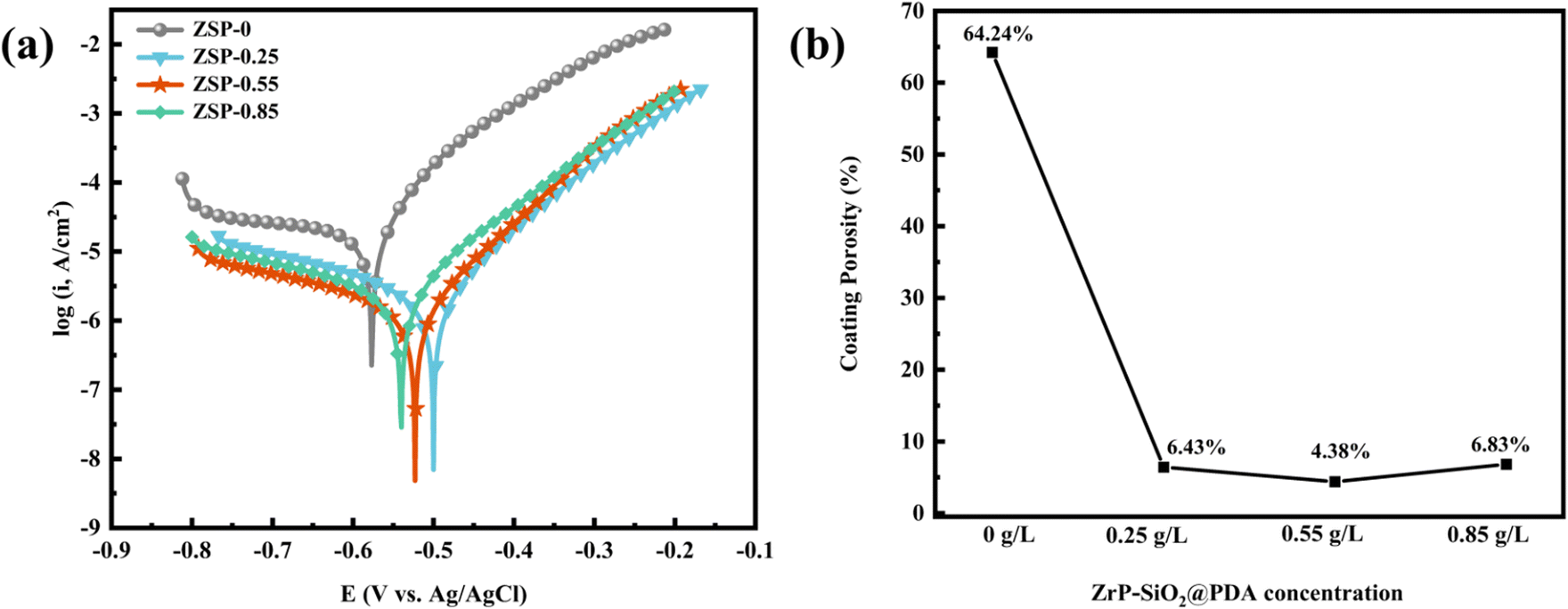 | ||
| Fig. 7 Potentiodynamic polarization curves (a) and coating porosity (b) of phosphate coatings with different content of PDA@α-ZrP/SiO2. | ||
| Specimens | Ecorr (V) | Icorr (A cm−2) | Rp (Ω cm2) | βa (mV dec−1) | βc (mV dec−1) | CR (mpy) |
|---|---|---|---|---|---|---|
| ZSP-0 | −0.55 | 2.55 × 10⁻⁵ | 1381 | 10.78 | −1.58 | 3.72 |
| ZSP-0.25 | −0.47 | 2.10 × 10⁻⁶ | 14042 |
10.65 | −4.11 | 0.31 |
| ZSP-0.55 | −0.49 | 1.45 × 10⁻⁶ | 20520 |
10.81 | −3.86 | 0.21 |
| ZSP-0.85 | −0.50 | 2.75 × 10⁻⁶ | 13184 |
9.13 | −2.88 | 0.40 |
The porosity of the phosphate coatings was also analyzed and calculated. The following formula is used to calculate the porosity of phosphate coatings.38

Among them, P, Rps and Rp respectively represent the porosity of phosphate coating, the polarization resistance of bare metal substrate and phosphate coating. ΔEcorr is the corrosion potential difference between the bare metal substrate and phosphate coating sample and and βa represents the anode slope. The test data of the baremetal substrate are listed in Table 2, where Ecorr is −0.62 V and the Rp is 874 Ω cm2. The coating porosity of the phosphate coatings was calculated through the above formula and the results were plotted in Fig. 7b. The porosity of the blank phosphate coating is 64.24%. When the PDA@α-ZrP/SiO2 was introduced, the porosity of the phosphate coatings drops below 10%. The reduction in porosity effectively enhances the corrosion resistance of phosphate coatings.
| Specimens | Ecorr (V) | Icorr (A cm−2) | Rp (Ω cm2) |
|---|---|---|---|
| Bare metal substrate | −0.62 | 2.53 × 10⁻⁵ | 874 |
EIS, as a rapid and minimally invasive inspection method, was conducted to evaluate the corrosion resistance of phosphate coatings.39–41 The Nyquist and Bode plots of ZSP-0, ZSP-0.25, ZSP-0.55, and ZSP-0.85 are illustrated in Fig. 8. The Nyquist plot reveals a direct correlation with the corrosion resistance of phosphate coatings. Specifically, ZSP-0.55 displays the largest arc radius among all simples, indicating its superior corrosion resistance (Fig. 8a). Furthermore, the impedance modulus (|Z|0.01 Hz) at 0.01 Hz frequency is used to analyze the barrier properties of the phosphate coatings. The higher |Z|0.01 Hz value indicates that the phosphate coating has better blocking effect on corrosive media.42,43 In Fig. 8b, |Z|0.01 Hz values of phosphate coatings decrease in the following order: ZSP-0.55 > ZSP-0.25 > ZSP-0.85 > ZSP-0, revealing that the incorporation of PDA@α-ZrP/SiO2 positively impacted the corrosion resistance of phosphate coating. Nevertheless, ZSP-0.85 sample exhibited a lower |Z|0.01 Hz value compared to that of the ZSP-0.55 sample, which may be that when a large amount of PDA@α-ZrP/SiO2 was introduced, PDA@α-ZrP/SiO2 would occupy the nucleation position of phosphate crystals and thus affect the film-forming effect of phosphate coatings. In Fig. 8c, compared with the blank phosphate coating, the nanocomposite phosphate coatings have the higher and wider phase angle, which also confirms that PDA@α-ZrP/SiO2 has great promotion effect on the phosphating process.
 | ||
| Fig. 8 EIS Nyquist plots (a), EIS Bode plots of different phosphate coatings (b and c), and the equivalent electrical circuit (d). | ||
To delve deeper into the corrosion resistance of phosphate coatings, a comprehensive analysis of EIS data was undertaken utilizing the equivalent circuit illustrated in Fig. 8d. The electrochemical parameters are documented in Table 3. Rs, Rc, Rct, CPEc and CPEdl symbolize the solution resistance, coating pore resistance, charge transfer resistance, coating capacitance and double-layer capacitance.44 High Rc and low CPEc usually indicate reduced permeability to H2O and O2. Remarkably, the ZSP-0.55 sample has the peak Rc value among the tested samples, affirming its supreme corrosion resistance. Additionally, the Rct value of ZSP-0.55 is significantly higher than that of ZSP-0, underscoring a dramatic boost in corrosion inhibition. This pronounced improvement is attributed to the small porosity of ZSP-0.55.
| Specimens | Rs (Ω cm2) | CPEc | Rc (Ω cm2) | CPEdl | Rct (Ω cm2) | ||
|---|---|---|---|---|---|---|---|
| Y (Ω−1 cm−2 sn) | n | Y (Ω−1 cm−2 sn) | n | ||||
| ZSP-0 | 34 | 4.9 × 10⁻⁵ | 0.64 | 612 | 1.4 × 10⁻⁵ | 0.70 | 5029 |
| ZSP-0.25 | 35 | 7.7 × 10⁻⁶ | 0.67 | 1097 | 8.0 × 10⁻⁶ | 0.52 | 54840 |
| ZSP-0.55 | 34 | 4.0 × 10⁻⁶ | 0.57 | 1881 | 2.4 × 10⁻⁶ | 0.64 | 57890 |
| ZSP-0.85 | 34 | 4.5 × 10⁻⁶ | 0.61 | 1235 | 1.6 × 10⁻⁶ | 0.61 | 28320 |
The copper sulfate dropping test was further carried out to test the corrosion resistance of phosphate coatings. The principle of the copper sulfate dropping test is that a substitution reaction occurs between CuSO4 and Fe in the metal substrate, resulting in discoloration. The length of discoloration time is used to determine the porosity and ability to block corrosive media of phosphate coatings. The results are shown in Fig. 9. Discoloration time of the blank phosphate coting is only 180 s. When the 2D/0D nanocomposite material was introduced, the discoloration time becomes significantly longer, which is consistent with the results of electrochemical corrosion resistance test. Discoloration time of 0.55 g L−1 ZSP sample is 668 s, which also proves that the 2D/0D nanocomposite effectively reduced the coating porosity and enhanced the shielding effect of phosphate coating on corrosive media.
 | ||
| Fig. 9 The time for color changing of samples in copper sulfate dropping experiments. | ||
From the study of mechanism of traditional phosphating, the reactions that occur during phosphating process are as follows:
| Fe + 2H+ → Fe2+ + H2↑; |
| H3PO4 → H2PO4− + H+ → HPO42− + 2H+ → PO43− + 3H+; |
| 3Fe2+ + 2PO43− + 8H2O → Fe3(PO4)2·8H2O; |
| 2Zn2+ + Fe2+ + 2PO43− + 4H2O → Zn2Fe(PO4)2·4H2O↓; |
| 3Zn2++ 2PO43− + 4H2O → Zn3(PO4)2·4H2O↓. |
In addition, PDA uses its own adhesion to wrap the nanoparticles, so that the nanoparticles show strong stability in the phosphating solution. Moreover, the catechol is strong ligand for metal ions including Fe2+ and Zn2+, which also allows the metal ions at the interface between substrate and phosphating solution to reach saturation faster and generate more phosphate crystals. The corrosion resistance and friction resistance of the more uniform and dense phosphate coating are enhanced.
4. Conclusions
In this study, α-ZrP and SiO2 nanocomposites modified with PDA were introduced into the phosphating solution and used as new phosphate accelerators. SEM results confirms that PDA@α-ZrP/SiO2 effectively increased the number of phosphating nucleation in the initial stage of phosphate coating formation and further improved the coverage of phosphate coating on the metal substrate. It not only improves the friction resistance, but also enhances the corrosion resistance of phosphate coating. The friction coefficient of phosphate coating was reduced from 0.32 to about 0.02. In the corrosion resistance test, Rp of blank phosphate coating is 1381 Ω cm2, while Rp of ZSP-0.55 could be increased to 20520 Ω cm2. And the coating porosity of phosphate coatings dropped from 64.24% to 4.38% via the incorporation of PDA@α-ZrP/SiO2. 2D/0D nanocomposites provide feasible solution to promote phosphating and reduce phosphating deposits.
Data availability
The authors confirm that the data supporting the findings of this study are available within the article.Conflicts of interest
There are no conflicts of interest to declare.Acknowledgements
This work was supported by the Hongliu Outstanding Young Talent Support Program of Lanzhou University of Technology (Grant No. 062313); the Centrally Guided Local Science and Technology Development Fund Project (Grant No. 22ZY1QA011); and the Lanzhou Talent Innovation and Entrepreneurship Project (Grant No. 2023-RC-46).References
- A. H. Riyas, C. V. Geethanjali, S. Arathy, A. Anil and S. M. A. Shibli, Appl. Surf. Sci., 2022, 593, 153370 CrossRef CAS.
- W. Wang, Y. Tian, H. Shen and X. Zhang, J. Alloys Compd., 2023, 955, 170247 CrossRef CAS.
- J. Wu, Y. Chen, L. Zhang and X. Sheng, J. Ind. Eng. Chem., 2024, 129, 424–434 CrossRef CAS.
- Y. Tian, H. Huang, H. Wang, Y. Xie, X. Sheng, L. Zhong and X. Zhang, J. Alloys Compd., 2020, 831, 154906 CrossRef CAS.
- S. Silva-Fernández, B. Díaz, I. Feijoo, X. R. Nóvoa and C. Pérez, Electrochim. Acta, 2023, 457, 142510 CrossRef.
- X. Huang, Q. Weng, Y. Chen, L. Zhang and X. Sheng, Surf. Interfaces, 2024, 45, 103911 CrossRef CAS.
- R. Ramanauskas, O. Girčienė, L. Gudavičiūtė and A. Selskis, Appl. Surf. Sci., 2015, 327, 131–139 CrossRef CAS.
- S. Silva-Fernández, B. Díaz, R. Figueroa, X. R. Nóvoa and C. Pérez, Surf. Coat. Technol., 2024, 476, 130260 CrossRef.
- X. He, J. Wu, Y. Chen, L. Zhang and X. Sheng, Appl. Surf. Sci., 2022, 603, 154455 CrossRef CAS.
- H. Yue, D. Wang, J. Zhu and L. Li, ACS Sustain. Chem. Eng., 2017, 5, 3019–3026 CrossRef CAS.
- M. A. Hafeez, A. Farooq, A. Zang, A. Saleem and K. M. Deen, J. Coat. Technol. Res., 2020, 17, 827–849 CrossRef CAS.
- E. Rumyantsev, V. Rumyantseva and V. Konovalova, Coatings, 2022, 14, 498 CrossRef.
- D. P. Burduhos-Nergis, A. V. Sandu, D. D. Burduhos-Nergis, P. Vizureanu and C. Bejinariu, Arch. Metall. Mater., 2023, 68, 1029–1034 CAS.
- Y. Xie, M. Chen, D. Xie, L. Zhong and X. Zhang, Corros. Sci., 2017, 128, 1–8 CrossRef CAS.
- H. Khosravi, R. Naderi and B. Ramezanzadeh, Mater. Today Chem., 2023, 27, 101282 CrossRef CAS.
- M. Tamilselvi, P. Kamaraj, M. Arthanareeswari, S. Devikala and J. A. Selvi, Appl. Surf. Sci., 2015, 332, 12–21 CrossRef CAS.
- M. Tamilselvi, P. Kamaraj, M. Arthanareeswari and S. Devikala, Appl. Surf. Sci., 2015, 327, 218–225 CrossRef CAS.
- M. Arthanareeswari, P. Kamaraj, M. Tamilselvi and S. Devikala, Mater. Today: Proc., 2018, 5, 9012–9025 CAS.
- M. Tamilselvi, P. Kamaraj, M. Arthanareeswari, S. Devikala, J. Arockiaselvi and T. Pushpamalini, Mater. Today: Proc., 2018, 5, 8880–8888 CAS.
- H. Huang, H. Wang, Y. Xie, D. Dong, X. Jiang and X. Zhang, Surf. Coat. Technol., 2019, 374, 935–943 CrossRef CAS.
- S. Hu, M. Muhammad, M. Wang, R. Ma, A. Du, Y. Fan, X. Cao and X. Zhao, Mater. Lett., 2020, 265, 127256 CrossRef CAS.
- M. Wang, R. Ma, A. Du, S. Hu, M. Muhammad, X. Cao, Y. Fan, X. Zhao and J. Wu, Mater. Chem. Phys., 2020, 250, 123056 CrossRef CAS.
- X. He, S. Li, J. Wu, Y. Chen, L. Zhang and X. Sheng, Ind. Eng. Chem. Res., 2022, 61, 12576–12589 CrossRef CAS.
- Y. Ma, H. Huang, H. Zhou, M. Graham, J. Smith, X. Sheng, Y. Chen, L. Zhang, X. Zhang, E. Shchukina and D. Shchukin, J. Mater. Sci. Technol., 2021, 95, 95–104 CrossRef CAS.
- H. Jiang, J. Li, Y. Xie, H. Guo, M. He, X. Shi, Y. Mei, X. Sheng and D. Xie, J. Mater. Sci. Technol., 2025, 209, 207–218 CrossRef.
- Y. Fan, J. Wu, L. Zhang and X. Sheng, Ind. Eng. Chem. Res., 2024, 63, 10637–10650 CrossRef CAS.
- X. He, J. Wu, S. Li, Y. Chen, L. Zhang and X. Sheng, Prog. Org. Coat., 2022, 171, 107042 CrossRef CAS.
- J. Li, F. Meng, L. Liu, Y. Cui, R. Liu, H. Zheng and F. Wang, Corros. Commun., 2022, 5, 62–72 CrossRef.
- Y. Tian, W. Qiu, Y. Xie, H. Huang, J. Hu, L. Zhong, X. Jiang and X. Zhang, J. Electrochem. Soc., 2020, 167, 101505 CrossRef CAS.
- B. Ramezanzadeh, Z. Haeri and M. Ramezanzadeh, Chem. Eng. J., 2016, 303, 511–528 CrossRef CAS.
- Y. Zhao, Y. He, S. Yan, C. Li, H. Li, W. Chen, J. Yan, G. Wu and X. Yuan, Colloids Surf., A, 2023, 656, 130472 CrossRef CAS.
- R. Amini and A. A. Sarabi, Appl. Surf. Sci., 2011, 257, 7134–7139 CrossRef CAS.
- X. He, Q. Weng, R. Guo, L. Zhang, X. Sheng and D. Xie, J. Mater. Sci. Technol., 2024, 201, 197–209 CrossRef.
- X. Chang, X. Chen, Q. Zhang, Y. Lei, D. Wang, J. Li and S. Sun, Corros. Commun., 2021, 4, 1–11 CrossRef.
- Q. Weng, L. Zhang, X. Sheng and D. Xie, J. Mater. Sci. Technol., 2024 DOI:10.1016/j.jmst.2024.07.023.
- A. Kumar, H. Rachwani and M. Kumar Singh, Proc. Inst. Mech. Eng., Part J., 2024, 238, 662–675 CrossRef CAS.
- Y. Tian, L. Zhong, X. Sheng and X. Zhang, Adv. Compos. Hybrid Mater., 2022, 5, 1922–1938 CrossRef CAS.
- B. Elsener, A. Rota and H. Böhni, Mater. Sci. Forum, 1991, 44–45, 29–38 Search PubMed.
- P. Zhou, L. Yang, Y. Hou, G. Duan, B. Yu, X. Li, Y. Zhai, B. Zhang, T. Zhang and F. Wang, Corros. Commun., 2021, 1, 47–57 CrossRef.
- B. Rebbah, A. El Haib, S. Lahmady, I. Forsal, M. Gouygou, S. Mallet-ladeira, A. Medaghri-alaoui, E. M. Rakib and A. Hannioui, RSC Adv., 2024, 14, 14152–14160 RSC.
- Q. A. Yousif, Z. Fadel, A. M. Abuelela, E. H. Alosaimi, S. Melhi and M. A. Bedair, RSC Adv., 2023, 13, 13094–13119 RSC.
- P. Li, Z. Shao, W. Fu, W. Ma, K. Yang, H. Zhou and M. Gao, Corros. Commun., 2023, 9, 44–56 CrossRef.
- Z. Huang, Q. Yong and Z.-H. Xie, Corros. Commun., 2023, 10, 38–47 CrossRef.
- M. Cui, D. I. Njoku, B. Li, L. Yang, Z. Wang, B. Hou and Y. Li, Corros. Commun., 2021, 1, 1–9 CrossRef.
| This journal is © The Royal Society of Chemistry 2024 |