
 Open Access Article
 This Open Access Article is licensed under a
 Creative Commons Attribution 3.0 Unported Licence
Catalyst coated membranes for fuel cell and water electrolyser delamination induced by organic solution soaking and water ultrasonication†
Tanongsak
Yingnakorn
 ab,
Jennifer
Hartley
a,
Molly E.
Keal
a,
Ross
Gordon
c,
Daniel Marin
Florido
c,
Andrew P.
Abbott
a and
Jake M.
Yang
*a
ab,
Jennifer
Hartley
a,
Molly E.
Keal
a,
Ross
Gordon
c,
Daniel Marin
Florido
c,
Andrew P.
Abbott
a and
Jake M.
Yang
*a
aSchool of Chemistry, University of Leicester, Leicester, LE1 7RH, UK. E-mail: jake.yang@leicester.ac.uk
bSchool of Metallurgical Engineering, Suranaree University of Technology, Nakhon Ratchasima 30000, Thailand
cJohnson Matthey Technology Centre, Blounts Court Road, Sonning Common, RG4 9NH, UK
First published on 10th March 2025
Abstract
This study presents a novel room-temperature, two-step process for separating catalyst-coated membranes (CCMs) used in fuel cells and water electrolysers. The method not only achieves a clean separation of the central membrane from the catalyst materials but also preserves the catalyst, thereby avoiding any potential hazardous gas release. The process involves a brief one-minute soak in an optimised solution, followed by a 10–12 minutes low-power ultrasonic treatment in water. The effectiveness of various organic (acetone, ethanol, ethylene glycol, hexane, and toluene) and aqueous (CaCl2, HCl, NaOH, NH4Cl) soaking solutions was thoroughly investigated to identify the optimal conditions for achieving near-pristine, separated membranes. This safe and efficient approach offers a promising strategy for CCM recycling, promoting resource recovery and economic benefits in clean energy technologies.
Sustainability spotlightThe UK government estimated that in 2040, there will be a four-fold increase in demand for critical minerals for clean energy technologies compared to today. In this work, we outlined the issues of recycling catalyst-coated membranes (CCMs) currently facing industries, and we developed a novel, efficient and green approach that recovers catalytic materials from CCMs in fuel cells and water electrolysers. The novelty of this work includes ultrasonic delamination at room temperature, usage of low-toxicity organic solvents and rapid separation of the Nafion central membrane (high-value material), which is otherwise lost in pyrometallurgical operations. Our methodology aligns with UN sustainable development goals 9, 12 and 13: Innovation and Infrastructure, Responsible Consumption and Production, and Climate Action. |
Introduction
In the endeavour to decarbonise energy production, there is a global shift towards renewable energy technologies.1,2 Hydrogen is one alternative energy source, and electrolysis is an important tool for the production of hydrogen and oxygen, and fuel cells are important to recombine them to make clean electricity.1–3 Both of these technologies require significant use of platinum group metals and proton exchange membranes.4,5 The most commonly used fluorinated membranes are made from perfluorinated sulfonic acid (PFSA) ionomers such as Nafion®, which contain a polytetrafluoroethylene backbone with sulfonic acid terminated side-chains, typically 8 to 80 μm thick.6–8 The perfluorinated backbones provide chemical stability, whilst the sulfonic acid groups facilitate proton conductivity.9 However, the sulfonated tetrafluoroethylene-based polymer significantly reduces conductivity beyond 90 °C due to dehydration and subsequent loss of water molecules.10 Aquivion® has a similar structure to Nafion, but features a shorter side chain.5 This modification enhances its glass transition temperature, water retention capability, thermal stability and ion conductivity while also reducing hydrogen crossover.11 Non-fluorinated membranes, including sulfonated poly(arylene ether ketone), sulfonated polyethersulfone, polybenzimidazole-based polymer, and polystyrene-sulfonic acid, also present viable options for proton exchange membrane applications.8,9,12 However, these are less common than the fluorinated polymers.13–15 Despite the known presence of per- and polyfluoroalkyl substances (PFAS) in fuel cell components, the degradation pathways under normal operating conditions are not well-defined. However, the potential for these compounds to degrade under harsh conditions over time and subsequently contribute to environmental contamination necessitates careful consideration.16 In particular, PFSA, a subgroup of PFAS, poses a toxic risk to aquatic fauna, insects, amphibians, and humans.17,18 Exposure pathways include drinking water and plant uptake, with certain PFAS variants associated with severe health consequences such as cancer, hepatic and neurological damage, and developmental abnormalities.16 With an estimated half-life of 10 to 100 years for PFAS side-chain polymer hydrolysis in soil and water, the environmental persistence of PFSA is a significant concern.17,18 Consequently, the longevity of the product in the environment, coupled with the increased cost and demand for PFSA Ionomers, makes its recovery at end-of-life (EOL) important.19–22In both proton exchange membrane fuel cells and water electrolysers, the proton exchange membrane is ‘sandwiched’ by catalysts, as shown in Fig. S1.†19,23 This catalyst-coated membrane (CCM) has different coating compositions based on the desired function. For fuel cells, platinum nanoparticles (Pt NPs) of ca. 2–5 nm diameter adsorbed onto carbon particles form the catalytic material on both the cathode and anode sides of the membrane. However, the CCM for the water electrolyser generally has Pt NPs on the cathode side, with iridium (Ir) and ruthenium (Ru) oxide particles being the primary choice for the anodic catalyst.24 Pt NPs have good catalytic activity, the ability to endure demanding operational conditions, and high resistance against corrosion,25 while the carbon support ensures electrical conductivity within the catalytic layers.26,27 Similarly, Ir and iridium oxide (IrOx) are preferred to Ru or Pt due to their favourable catalytic characteristics and superior corrosion resistance,28,29 particularly towards the oxygen evolution reaction.19 However, iridium's scarcity and significantly higher cost compared to platinum present a potential bottleneck to the large-scale commercialisation of the CCM for the water electrolyser and their ability to meet maturing market demands.30–32
Current recycling technologies focus on recovering the platinum group metal (PGM) catalysts from proton exchange membrane stacks, as this is where the majority of the value is present. Recovery of the other components, such as the polymer and the carbon support, are often incidental to PGM recovery,20,33 even though the value of the ionomer is the substantial cost, constituting approximately 10% of the total cell cost within the proton exchange membrane (PEM) stack.34–36 Recovery methods for the PGMs include pyrometallurgical and hydrometallurgical routes. The pyrometallurgical routes involve very high-temperature (reaching up to 1100 °C) smelting processes to concentrate the PGMs from spent PEMs. This typically involves combusting organic components, such as PFSA ionomers, resulting in a concentrated metal residue. However, this method presents challenges related to potential emissions of harmful gases and low selectivity in extracting certain PGMs.37,38 Therefore, the pyrometallurgical process is usually followed by hydrometallurgical processes, where valuable metals are then leached out of the mixed-metal slurry using concentrated corrosive acids. The PGM concentrates from smelting operations are then processed through hydrometallurgical refining processes, which involve dissolution and subsequent separation of the individual metals. Alternatively, PGM can be recovered directly using hydrometallurgical routes where metals or metal oxide NPs are leached from the CCM using caustic or acidic agents, followed by separation of the different components via solvent extraction, distillation, ion exchange, cementation, or filtration.6,20,39 An example schematic flow diagram is shown in Fig. S2 and Table S1.†
The principal advantages associated with hydrometallurgical approaches include their notable selectivity towards metals, relatively modest energy requirements, and the potential for reusing reaction components. However, these can degrade the membrane polymers and form secondary pollutants, posing environmental issues.40
Organic solvents, such as alcohols, can be used to recover the membrane polymers as the catalytic coating is detached from the membrane by disrupting the adhesive bond.41 Carmo et al. separated the cathode and anode catalysts by circulating a deionised water and alcohol mixture, resulting in a nearly pristine fluoropolymer membrane within 10–30 minutes.33 Similarly, Xu and co-workers demonstrated the isolation of a Nafion 115 membrane from proton exchange membrane fuel cells by boiling in isopropanol for 20 minutes, followed by mechanical removal of catalyst traces.42 Supercritical media have also been used to separate fluorinated polymers and ionomers from precious metal-containing fuel cell components. This occurred in a pressure reactor at 350–450 °C and 200–400 bar pressure for 1–10 hours, with no reported emissions of fluorine-containing substances (HF, F2, or fluorides).43 However, the majority of these recycling processes require elevated temperatures and pressures, which can be energy-intensive. To that end, Johnson Matthey has recently developed the HyRefine™ process, which enables recovery of the PGM and the valuable PFSA ionomer together. This process uses chemical routes to improve the efficiency and sustainability of CCM recycling compared to conventional PGM refining.44
This study presents an alternative effective, room-temperature recycling process to separate PFSA ionomer membranes from catalyst coatings in fuel cell and water electrolyser CCMs. The method involves two stages: firstly, soaking the CCMs in a range of organic solvents to expand the membrane and, secondly, application of ultrasound in water to delaminate the catalyst-coated layers from the membrane. The ultrasound process has low energy consumption, as it is performed at room temperature, and the coating is delaminated within a few minutes. Ultrasound with low power levels (<1000 W) has previously been employed in cleansing, blending, and expediting mechanical and chemical processes,45,46 whereas high power ultrasound (>1000 W) has previously been used for delaminating more challenging substrates such as metal oxide coatings from electric vehicle battery electrodes.45 The method of action for removal of material from substrates is thought to be due to the collapse of cavitation bubbles, inducing the formation of micro-jets, shockwaves, and micro-streaming. The enhanced mass transport will improve molecular-scale mixing or cleaning,47 while the cavitation can fracture brittle coatings or the interfacial connections between layers.48,49
Experimental
Materials
Production scrap materials such as fuel cell CCM, water electrolyser CCM, and pristine PFSA ionomer membrane were provided by Johnson Matthey. The CCMs were composed of a polymer membrane coated on both sides with an active catalyst material containing different mixtures of Pt NPs on carbon and either IrOx particles or IrOx particles that are infused with one other transition metal to achieve better stability for the desired application (IrMOx). The solvents used for soaking the polymers were acetone (Fisher Scientific, ≥99.5%), ethanol (VWR, ≥99.8%), toluene (Fisher Scientific, extra pure, low in sulfur), hexane fraction from petroleum (Fisher Scientific, laboratory-grade), and ethylene glycol (Sigma-Aldrich, 99.8%). Aqueous solutions of ammonium chloride (VWR, 98%), sodium hydroxide (NaOH) (Sigma-Aldrich, >98%), hydrochloric acid (Fisher Scientific, 37%), calcium chloride hexahydrate (Thermo Scientific, 98+%), or choline chloride (Thermo Scientific, 99%) were also investigated.Soaking and delamination methods
The methodology involves two primary steps: the soaking of fuel cell and water electrolyser CCM samples, approximately 10 × 10 mm2 in size (equivalent to ca. 7 mg for fuel cell and 25 mg for water electrolyser CCMs), in various solutions, followed by delamination using an ultrasonic bath in water. For the soaking step, organic solvents such as acetone, ethanol, methanol, and ethylene glycol were tested, as well as aqueous solutions including deionised water, 1 M ammonium chloride, 1 M sodium hydroxide, 1 M hydrochloric acid, 1 M calcium chloride hexahydrate, and 1 M choline chloride. The soaking durations ranged from 10 seconds to 6 minutes. It was found that methanol was unsuitable for membrane swelling due to its observed flammability when in contact with the catalytic coating. During the delamination process, the soaked CCM samples were subjected to sonication in 10 mL of water. Sonication was performed using an ultrasonic bath (Fisherbrand® FB15055, 200–240 V, 50/60 Hz, 550 W) to detach the catalyst-coated material from the ion-exchange membrane. The sonication times varied between 2 and 12 minutes at ambient temperature (15 to 20 °C). This was followed by an additional 2 minutes of sonication in fresh deionised water to remove any contamination. The delamination percentage was evaluated by comparing the mass of the cleaned membrane sample to its initial mass before sonication. To make 100% clean membrane reference samples for comparison purposes, the cleaned membranes were immersed in ethanol for 1 minute, followed by sonication in deionised water for 30 minutes (one sample, 10 × 10 mm2, per 10 mL of water). A second sonication in fresh deionised water was conducted for an additional 10 minutes to ensure thorough cleaning.The swelling behaviour of the PFSA ionomer membrane was investigated using a membrane obtained from the uncoated edge of the water electrolyser CCM (ca. 80 μm thick). Samples measuring approximately 20 × 5 mm2 were immersed in a range of solutions, both organic and aqueous, to assess their expansion ratios. Measurements were conducted by capturing images using an Inspex HD 1080p instrument at intervals ranging from 2 to 6 minutes. The length changes were then measured and compared to the original length.
Instrumentation
Scanning electron microscopy (SEM, Zeiss Gemini 360 FEGSEM) and energy-dispersive X-ray spectroscopy (EDS, Oxford Instruments Ultim Extreme windowless detector) were used to characterise the morphology and elemental composition of the samples. The SEM was operated in in-lens mode with an accelerating voltage of 1 kV with a 5 nm spot size for imaging. The EDS analysis was performed at an accelerating voltage of 5–15 kV, controlled using Aztec software.The particle size and the contribution of catalytic materials were analysed by transmission electron microscopy (TEM). The initial samples were soaked in acetone for one minute and physically separated on each side in water. The delaminated particles obtained post-experiment were directly sampled from the delaminated aqueous solution. A JEOL JEM-1400 TEM instrument with an accelerating voltage of 120 kV was utilised to examine the morphology of the samples and ascertain the size of Pt NPs on both sides of CCMs. To facilitate this analysis, samples were prepared by depositing colloidal suspension drops onto copper grids, which were air-dried for approximately 1 hour before imaging.
Fourier transform infrared (FTIR) spectroscopy was used to identify the polymer present in the membrane and binder materials. The pristine and water electrolyser membranes could be directly analysed, but the fuel cell membrane had to be measured after delamination due to there being no exposed membrane available. The samples were placed above the light source in a Bruker Alpha II spectrometer instrument, controlled by the corresponding Bruker software on the computer monitor. The scan range was 4000 to 400 cm−1, and the spectrum containing peaks was related to the magnitude of transmittance. The polymers were identified by comparing the measured spectra for the end-of-life membranes to existing literature data, and the identification was confirmed by recording standard samples.
A Mettler Toledo TGA/DSC1 instrument with a resolution of ±1 μg and a maximum temperature of 1100 °C was used to measure sample mass change and heat flow, controlled by STARe software (version 12.10). The balance used to weigh the samples was a Mettler Toledo Semi-Micro Balance (MS105DU), with a resolution of 0.1 mg. The samples were placed in 100 μL aluminium crucibles in all experiments, with no lid. The temperature that operated in the program was from 25 to 600 °C with a heating rate of 5 K min−1 and a nitrogen flow rate of 75 mL min−1.
Results and discussion
Raw materials characterisation
Production scrap fuel cell and water electrolyser CCMs were characterised using SEM/EDS to determine the morphology and chemical composition within the two CCMs. The disassembled fuel cell and water electrolyser CCMs have three distinct layers (central membrane and cover with two layers of catalyst-coated materials). Fig. 1a shows a photograph of the fuel cell CCM, and Fig. 1b shows a cross-sectional SEM image. The overall thickness is ca. 35 μm, and the central polymer membrane layer is 14.57 (±1.24) μm thick (see Fig. S4† for more details). EDS analysis indicated that the central membrane layer contains carbon (C), oxygen (O), fluorine (F), and sulfur (S), indicating the presence of the sulfur-containing fluorinated polymer. FTIR spectroscopy confirmed this to be the PFSA ionomer, which is consistent with the literature (see Fig. S5† for spectrum).20,50 The anodic catalytic coatings, the SEM image of which is shown in Fig. 1d, are found to predominantly contain 10.98 (±2.29) wt% Ir, 35.53 (±4.09) wt% Pt, 40.78 (±1.87) wt% C and 7.67 (±0.01) wt% F. This is fully consistent with a layer of fluorinated polymer binder coated with a mixture of Pt on carbon and IrMOx particles. On the flip side, the cathode catalytic coating, SEM image shown in Fig. 1c, is found to be loaded with more wt% of Pt (42.47 (±2.54)) compared to the anode, along with 53.00 (±1.90) wt% C and 3.9 (±1.27) wt% F. This is consistent with a cathode layer loaded with only Pt on carbon nanoparticles. Detailed EDS element mapping of both the anodic and cathodic active material is shown in Fig. S6.† As illustrated in Fig. 1e and f, the TEM analysis reveals that the average sizes of the Pt-on carbon catalyst and the Pt, IrMOx nanoparticles cell reversal catalyst are 5.33 (±1.12) nm and 5.12 (±1.81) nm, respectively. The presence of fluorine in these catalytic coatings indicates the PFSA ionomer is also used as the binder.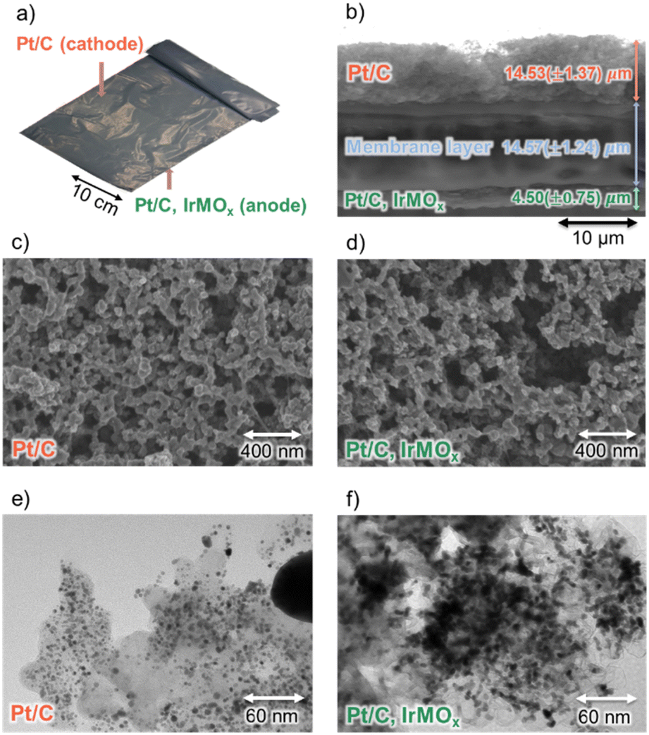 | ||
| Fig. 1 (a) Shows a photograph of the fuel cell CCM. (b) Provides a SEM image of the fuel cell cross-section. (c) and (d) Depict SEM images of the Pt/C cathode layer and the Pt/C, IrMOx anode layer. The displayed element compositions were obtained via sampling across the entire image. (e) and (f) Display TEM images of the Pt/C cathode and Pt/C, IrMOx anode particles within the fuel cell CCM, respectively. Fully EDS analysis and composition of the anode and cathode active materials are shown in Fig. S3 in ESI.† | ||
The water electrolyser is shown in Fig. 2. In contrast to the fuel cell CCM, the total thickness of the water electrolyser CCM is considerably larger (ca. 100 μm). It is composed of a polymer membrane measuring 80.37 (±0.85) μm, coated on the cathode side with a layer containing 39.06 (±2.37) wt% Pt, measuring 7.90 (±0.70) μm, and on the anode side with an IrOx layer containing 75.73 (±1.35) wt% Ir measuring 12.83 (±0.76) μm. (see element mapping in Fig. S7†).
 | ||
| Fig. 2 (a) Shows a photograph of the water electrolyser CCM. (b) Provides a SEM image of the water electrolyser CCM cross-section. (c) and (d) Illustrate the Pt/C and IrOx layers. (e) and (f) Present TEM images of the Pt/C and IrOx particles, respectively. | ||
The polymer is composed of 27.91 (±2.69) wt% C, 1.93 (±2.72) wt% O, 69.06 (±0.27) wt% F, and 1.12 (±0.29) wt% S, indicative of a PFSA ionomer composition. This was confirmed using FTIR spectroscopy (Fig. S5†). The average sizes of the Pt NPs on the carbon substrate and IrOx are 5.35 (±1.53) nm and 18.32 (±3.52) nm (Fig. 2e and f), respectively.
TGA/DSC results of the recovered materials and separated membranes are shown in ESI Fig. S8.† The typical polymer transitions expected for fluorinated binders, such as PVDF, PTFE and Nafion,51,52 were not observed in the DSC curves. This is likely a result of PGM-catalysed thermal decomposition of the PFSA ionomer, the latter present in both the central membrane and as binders within the catalyst layers.
Effect of catalyst coated membrane soaking on delamination with an ultrasonic bath
The effect of soaking the CCMS with various organic solvents on the delamination efficiency was investigated using water in an ultrasonic bath. Firstly, samples of fuel cell CCM were immersed in a selection of organic solvents (acetone, ethanol, and ethylene glycol) and aqueous solutions (CaCl2, HCl, NaOH, NH4Cl) for a fixed duration of 1 minute. After 1 minute of soaking, the CCM sample was transferred to pure water and sonicated for 10 minutes. It was found that CCMs treated with 1 minute in ethanol followed by 30 minutes of insonation produced pristine PFSA ionomer membranes and an additional 10 minutes of insonation with replaced fresh deionised water to ensure thorough cleaning, as shown in Fig. 3 below. This was considered an effective removal of the catalytic material from the PFSA ionomer membrane and is therefore used as a reference point to compare other pre-treatment and insonation conditions. | ||
| Fig. 3 Photos of (a) initial fuel cell CCM, (b) cleaned central fuel cell membrane, (c) initial water electrolyser CCM, and (d) cleaned central water electrolyser membrane. All images were taken on a white background for clarity of display. | ||
The subsequent changes in mass were quantified and compared with those of the reference samples (Fig. 3). The mass variations of the reference samples were 36.18 (±1.67)% for the fuel cell catalyst coated membrane (CCM) and 23.59 (±0.77)% for the water electrolyser CCM, relative to their initial mass prior to delamination. Fig. 4a depicts delamination percentages of fuel cell CCM. This study demonstrates that acetone and ethanol are more efficient solvents, ensuring the successful detachment of the central membrane while preserving a clean surface within 10 minutes. In contrast, water, when used without a prior soaking step in acetone or ethanol, resulted in an unclean membrane surface, as shown in Fig. 4c. Note that the rest of the solutions (ethylene glycol, CaCl2, HCl, NaOH, NH4Cl) demonstrate a significantly lower efficacy of delamination, potentially attributed to low solution absorption during solution immersion, resulting in failure to yield a clean membrane surface, as evidenced in Fig. S9 and S10.†
 | ||
| Fig. 4 Delamination percentage in water with an ultrasonic bath of (a) fuel cell CCM and (b) water electrolyser CCM after swelling in different solvents, (c) picture of fuel cell CCM and (d) water electrolyser CCM after soaking in acetone, ethanol, and water, followed by sonication in water (10 min for fuel cell CCM and 12 min for water electrolyser CCM). | ||
It is evident that the soaking pre-treatment of the CCMs in an organic solution is key to the effective separation of catalytic materials from the ionomer membrane. However, interestingly, direct sonication in the same organic solution resulted in lower efficiency delamination compared to the solvent followed by water steps. While the ionomer membrane swelled by 4–8% within minutes of immersion in acetone, ethanol, and ethylene glycol (comparable to swelling in water; Fig. S8a and b†), this suggests that swelling alone is not the primary driver of the subsequent sonication-driven delamination. Instead, the high efficiency of room-temperature delamination likely stems from a modification of the ionomer structure within the particle-loaded film, coupled with the enhanced effectiveness of ultrasound cavitation in water. Although the precise interaction between the soaking solvents (acetone or ethanol) and the ionomer membrane remains to be fully elucidated, it is relevant to note that extended exposure (6–24 hours) to ethanol/water mixtures in a reactor at elevated temperatures (about 250 °C) is known to dissolve PFSA membranes.53,54 However, the short duration (1 minute) and ambient temperature used in this study limit further mechanistic interpretation due to the scarcity of supporting evidence and literature.
This process was applied to the delamination of water electrolyser CCM (see Fig. S11†), yielding comparable results to the delamination of fuel cell CCM; however, the delamination step needed about 12 minutes (Fig. 4b) possibly due to a different ionomer type, catalyst loading and increased membrane thickness. The central membrane surface following sonication is presented in Fig. 4d. Furthermore, a one-minute ethanol soak achieves better results than acetone regarding membrane surface delamination within the operational timeframe.
Conversely, delamination using pure ethanol, pure acetone, a 50–50 mixture of ethanol–water or acetone–water, combined with ultrasonication, is ineffective at achieving a clean membrane surface (Fig. S12†). Investigations into the cavitation behaviour of different aqueous media under ultrasonic conditions show that the cavitation shockwaves at low kHz frequencies are more vigorous in water than in ethanol,55,56 which are highly likely to be due to the lower density, surface tension, and vapour pressure of the alcohol solutions resulting in unstable cavitation bubbles.57–59
The change in volume of the membrane during delamination with ethanol probably traps nanoparticles, complicating their separation. Additionally, the high alcohol content in contact with highly reactive metals during the delamination process can pose safety issues.
To optimise the soaking time in acetone and ethanol, a range of times from 10 seconds to 6 minutes was evaluated to minimise processing time whilst still maintaining a high delamination efficiency. The investigation revealed no statistically significant difference in delamination outcomes across the tested soaking times for acetone (see Fig. S13†). However, after 4 minutes of soaking in ethanol, a lower delamination efficiency was observed due to variations in the swelling and shrinking behaviour of the polymer membrane, especially for the thicker membrane of water electrolyser CCM in ethanol for 6 minutes (Fig. S14†). This suggests a rapid interaction between the solvents and the membrane material. As a result, a soaking time of 1 minute in ethanol was implemented, ensuring adequate sample hydration as a standard pre-treatment protocol for subsequent experiments. Additionally, the influence of solvents on membrane swelling was investigated. PFSA Ionomer membranes were submerged in various organic solvents (acetone, ethanol, ethylene glycol, hexane, and toluene) and aqueous solutions (CaCl2, HCl, NaOH, and NH4Cl), as shown in Fig. S15.† However, these observed variations in swelling did not demonstrably influence the delamination process.
Membranes and particles after ultrasonic delamination
The delaminated membranes exhibited deformation due to softening during soaking and delamination, leading to bending and increased foldability on a macro scale after drying. Despite this, they retained their sheet-like form, similar to the initial samples, and no fractures were observed in this study, as evidenced by the images from Fig. 4c and d. The delaminated membranes were examined using SEM to assess their surface characteristics. Fig. 5 presents SEM images of the membrane surfaces after a one-minute ethanol soak and subsequent delamination in an ultrasonic water bath. Fig. 5a shows the delaminated membrane surface on the Pt/C cathode side of the fuel cell sample, which appears very clean. The membrane surface on the Pt/C, IrMOx anode side of the fuel cell sample (Fig. 5b) is also immaculate at a 10 μm scale and contains only traces of embedded particles on a 200 nm scale. Fig. 5c and d show the delaminated membranes on the Pt/C and IrOx sides of the water electrolyser CCM. Both sides appear very clean, as confirmed by the absence of catalyst-coated particles detectable by SEM. The EDS analysis of these delaminated membranes identified only constituents consistent with the PFSA ionomer: approximately 26–28 wt% C, 1–3 wt% O, 67–70 wt% F, and 1 wt% S. Notably, neither Pt nor Ir catalyst metals were detected. Furthermore, the chemical composition of the delaminated water electrolyser membrane closely matched that of the pristine membrane obtained from the uncoated edge of the water electrolyser CCM (see ESI Tables S2 and S3† for detailed compositional data). This observation substantiates the high efficiency of the delamination method employed in this study. Note that the dark holes in the Fig. 5 are artefacts from the SEM analysis. These voids are likely due to the evaporation of residual solvent causing bubble formation, a phenomenon which has also been observed in literature.60 The delaminated catalyst nanoparticles can be separated from the aqueous solution through several methods, including filtration, sedimentation and decantation, centrifugation, and water evaporation.61–65 | ||
| Fig. 5 SEM images of delaminated membranes; (a) and (b) are Pt/C and Pt/C, IrMOx sides of the fuel cell membrane, (c) and (d) are Pt–C and IrOx sides of water electrolyser membrane. | ||
Following delamination of the CCMs, the PFAS ionomer membrane was removed from the solution, and the remaining aqueous solution was dried in the oven at 60 °C for 24 hours. The dried particles were examined using TEM, as shown in Fig. 6. Notably, no fracturing of the carbon substrate or detachment of metal or metal compounds from the carbon surface was observed. This suggests that the low-power ultrasonic bath lacks the energy required to dislodge the nanoparticles from the carbon substrate and PFSA ionomer binder. This study introduces a facile method for separating both sides of the catalyst materials from the middle layer of the membrane. While this method effectively separates the catalyst materials, subsequent processing will necessitate separating these materials into distinct PGM streams, typically achievable through hydrometallurgical techniques (see Table S1† for examples of the processes). On the contrary, although the delamination process effectively isolates the membrane, its direct reuse in CCM fabrication for fuel cells or water electrolysers requires further testing. For example, the recovered membrane could be dissolved and recast.42,53,66 However, this approach offers several advantages over existing techniques. For example, it presents a more sustainable alternative to pyrometallurgical methods, which, while effective in removing the organic phase, result in the loss of valuable membrane material, potential release of noxious emissions, and high energy demands.37,38 Furthermore, the proposed method may surpass the limitations of direct membrane dissolution from spent CCMs using solvents such as ethanol, methanol (including aqueous mixtures), N,N-dimethylformamide (DMF), dimethyl sulfoxide (DMSO), and N,N-dimethylacetamide (DMAc) at elevated temperatures (ranging from 80 to 240 °C). These conventional dissolution methods often suffer from incomplete membrane dissolution and extended processing times (ranging from 6 hours to several days), occasionally necessitating high-pressure autoclave reactors.42,53,54,67 Moreover, this study demonstrates a simplified method for rapid separation of near-pure membrane and catalyst materials, achieving this within a short timeframe and with low power consumption. Furthermore, the proposed method is anticipated to be cost-effective. Specifically, the initial solvent soaking step (e.g., in ethanol or acetone) requires minimal chemical input. Sonication-induced delamination was performed in water without any chemical additives, and the post-separation water is potentially reusable within the process loop. We anticipate that this water delamination step does not introduce any chemical contaminants. Therefore, it is likely that the reprocessed catalysts can be directly remanufactured into new cells, contributing directly to short-loop recycling and the circular economy of critical elements. Additionally, the energy consumption for low-power sonication was measured to be 0.027 kW h per batch experiment, which is ca. 67 GBX based on the average industrial UK electricity cost.68
 | ||
| Fig. 6 TEM images of delaminated particles; (a) is a mixture of Pt/C and Pt/C, IrMOx sides from the fuel cell membrane, and (b) is a mixture of Pt/C and IrOx sides from water electrolyser membrane. | ||
Conclusions
This study demonstrates an effective bulk separation of the catalytic materials from PFSA ionomer membranes. Simply pre-soaking the scrap CCM with ethanol for 1 minute enables the active catalyst particles to be separated from the ionomer membrane following 12 minutes of insonation in water. The pre-soaking of CCM with ethanol is key to the rapid removal of active catalytic particles. This is likely due to a change in the ionomer structure of the particle-loaded ionomer film as evidenced by a non-insignificant degree of swelling of the membrane.This technology is a non-destructive method that allows a rapid separation of ionomer films from active catalytic particles in scrap fuel cells and water electrolyser CCMs. Furthermore, this method is anticipated to be applicable to analogous fuel cells and water electrolysers. Specifically, fuel cell and water electrolyser materials incorporating PFSA membranes and ionomers but with varying catalyst coating materials, such as platinum-free catalysts and non-carbon-based support materials,69–72 are posited as suitable candidates for this methodology. We envisage this work can be readily scaled up and adopted to first recover ionomer films prior to catalytic upcycle treatments, which would otherwise destroy or deform ionomer membranes.
Data availability
The data supporting this article have been included as part of the ESI.†Conflicts of interest
There are no conflicts to declare.Acknowledgements
The authors would like to thank the Faraday Institution (Faraday Institution grant code FIRG027, https://relib.org.uk), the UKRI Interdisciplinary Circular Economy Centre for Technology Metals, Met4Tech project (EP/V011855/1), and Johnson Matthey for their generous support and for providing scrap water electrolyser and fuel cell CCMs which enable this work. Furthermore, TY acknowledges support from the Royal Thai Government Scholarship and the Suranaree University of Technology.References
- M. Yue, H. Lambert, E. Pahon, R. Roche, S. Jemei and D. Hissel, Renewable Sustainable Energy Rev., 2021, 146, 111180 CrossRef.
- H. T. Xie, P. Oksen, X. Guo, X. He and Y. Bian, Progress in Hydrogen Fuel Cell Technology Development and Deployment in China, World Intellectual Property Organization, Geneva, Switzerland, 2022 Search PubMed.
- S. Shiva Kumar and V. Himabindu, Mater. Sci. Energy Technol., 2019, 2, 442–454 Search PubMed.
- H. Zhang and P. K. Shen, Chem. Soc. Rev., 2012, 41, 2382–2394 RSC.
- S. Radice, C. Oldani, L. Merlo and M. Rocchia, Polym. Degrad. Stab., 2013, 98, 1138–1143 CrossRef CAS.
- A. Valente, D. Iribarren and J. Dufour, Int. J. Hydrogen Energy, 2019, 44, 20965–20977 CrossRef CAS.
- W. G. Grot, US Pat., US3784399A, 1974 Search PubMed.
- A. Baroutaji, A. Arjunan, A. Alaswad, A. S. Praveen, T. Wilberforce, M. A. Abdelkareem and A.-G. Olabi, in Encyclopedia of Smart Materials, ed. A.-G. Olabi, Elsevier, Oxford, 2022, pp. 267–272 Search PubMed.
- N. H. Jawad, A. A. Yahya, A. R. Al-Shathr, H. G. Salih, K. T. Rashid, S. Al-Saadi, A. A. AbdulRazak, I. K. Salih, A. Zrelli and Q. F. Alsalhy, Sustainability, 2022, 14, 14653 CrossRef CAS.
- M. Casciola, G. Alberti, M. Sganappa and R. Narducci, J. Power Sources, 2006, 162, 141–145 CrossRef CAS.
- A. Ghielmi, P. Vaccarono, C. Troglia and V. Arcella, J. Power Sources, 2005, 145, 108–115 Search PubMed.
- A. Parekh, Front. Energy Res., 2022, 10, 956132 CrossRef.
- M. M. Tellez-Cruz, J. Escorihuela, O. Solorza-Feria and V. Compañ, Polymers, 2021, 13, 3064 CrossRef CAS PubMed.
- A. Carbone, R. Pedicini, G. Portale, A. Longo, L. D'Ilario and E. Passalacqua, J. Power Sources, 2006, 163, 18–26 CrossRef CAS.
- D. Aili, D. Henkensmeier, S. Martin, B. Singh, Y. Hu, J. O. Jensen, L. N. Cleemann and Q. Li, Electrochem. Energy Rev., 2020, 3, 793–845 CrossRef CAS.
- P. Von Tettau, P. Thiele, P. Mauermann, M. Wick, S. Tinz and S. Pischinger, J. Power Sources, 2025, 630, 236104 CrossRef CAS.
- H. Brunn, G. Arnold, W. Körner, G. Rippen, K. G. Steinhäuser and I. Valentin, Environ. Sci. Eur., 2023, 35, 20 CrossRef CAS.
- I. Rosato, T. Bonato, T. Fletcher, E. Batzella and C. Canova, Environ. Res., 2024, 242, 117743 CrossRef CAS PubMed.
- R. Stropnik, A. Lotrič, A. B. Montenegro, M. Sekavčnik and M. Mori, Energy Sci. Eng., 2019, 7, 2519–2539 CrossRef CAS.
- F. Xu, S. Mu and M. Pan, Int. J. Hydrogen Energy, 2010, 35, 2976–2979 CrossRef CAS.
- P. Sreeraj, R. Vedarajan, N. Rajalakshmi and V. Ramadesigan, Int. J. Hydrogen Energy, 2021, 46, 13020–13028 CrossRef CAS.
- S. Ahmad, T. Nawaz, A. Ali, M. F. Orhan, A. Samreen and A. M. Kannan, Int. J. Hydrogen Energy, 2022, 47, 19086–19131 CrossRef CAS.
- L. Zeng, Y. Wang, Y. Guo, X. Dai, L. Chen, C. He, N. T. H. Nhung, Y. Wei, G. Dodbiba and T. Fujita, Crystals, 2022, 12, 403 CrossRef CAS.
- S. S. Kumar and H. Lim, Sustainable Energy Fuels, 2023, 7, 3560–3583 RSC.
- X. Zhang, H. Li, J. Yang, Y. Lei, C. Wang, J. Wang, Y. Tang and Z. Mao, RSC Adv., 2021, 11, 13316–13328 Search PubMed.
- H. Liu, J. Zhao and X. Li, Electrochem. Energy Rev., 2022, 5, 13 CrossRef CAS PubMed.
- M. J. Lázaro, L. Calvillo, V. Celorrio, J. Pardo, S. Perathoner and R. Moliner, in book: Carbon Black: Production, Properties and Uses, Nova Science Publishers, Inc., 2011, pp. 41–68 Search PubMed.
- E. Antolini, ACS Catal., 2014, 4, 1426–1440 CrossRef CAS.
- T. Binninger, E. Fabbri, R. Kötz and T. J. Schmidt, J. Electrochem. Soc., 2013, 161, H121–H128 CrossRef.
- C. Minke, M. Suermann, B. Bensmann and R. Hanke-Rauschenbach, Int. J. Hydrogen Energy, 2021, 46, 23581–23590 CrossRef CAS.
- K. D. Rasmussen, H. Wenzel, C. Bangs, E. Petavratzi and G. Liu, Environ. Sci. Technol., 2019, 53, 11541–11551 CrossRef CAS PubMed.
- A. Lončar, D. Escalera-López, S. Cherevko and N. Hodnik, Angew Chem. Int. Ed. Engl., 2022, 61, e202114437 CrossRef PubMed.
- M. Carmo, G. P. Keeley, D. Holtz, T. Grube, M. Robinius, M. Müller and D. Stolten, Int. J. Hydrogen Energy, 2019, 44, 3450–3455 CrossRef CAS.
- R. Tao, M. Shao and Y. Kim, Chem.–Eur. J., 2024, 30, e202401208 CrossRef CAS PubMed.
- S. Mo, L. Du, Z. Huang, J. Chen, Y. Zhou, P. Wu, L. Meng, N. Wang, L. Xing, M. Zhao, Y. Yang, J. Tang, Y. Zou and S. Ye, Electrochem. Energy Rev., 2023, 6, 28 CrossRef CAS.
- S. K. Kamarudin, W. R. W. Daud, A. Md Som, M. S. Takriff and A. W. Mohammad, J. Power Sources, 2006, 157, 641–649 CrossRef CAS.
- S. A. Mvokwe, O. O. Oyedeji, M. A. Agoro, E. L. Meyer and N. Rono, Membranes, 2025, 15, 13 CrossRef CAS PubMed.
- D. Choi, D. Kwon, J. Nam, Y. F. Tsang, S. Jung, K. Kwon and E. E. Kwon, Chem. Eng. J., 2024, 484, 149251 CrossRef CAS.
- L. Duclos, L. Svecova, V. Laforest, G. Mandil and P. X. Thivel, Hydrometallurgy, 2016, 160, 79–89 CrossRef CAS.
- M. Kutter, C. Greve, M. Maier, M. Schilling, A. Mauel, A. Hilgert, H. Hoffmann, W. Hagemeier, A. Rosin, M. Muggli, R. Zeis, J. Senker, T. Böhm, E. M. Herzig, T. Gerdes and C. Roth, J. Membr. Sci., 2024, 693, 122370 CrossRef CAS.
- L. Shore, US Pat., US8124261B2, 2012 Search PubMed.
- H. F. Xu, X. Wang, Z. G. Shao and I. M. Hsing, J. Appl. Electrochem., 2002, 32, 1337–1340 CrossRef CAS.
- J. Koehler, R. Zuber, M. Binder, V. Baenisch and M. Lopez, US Pat., US7713502B2, 2010 Search PubMed.
- Johnson Matthey demonstrates key step towards a circular hydrogen economy, https://matthey.com/media/2023/hyrefine, accessed 19 July, 2024 Search PubMed.
- C. Lei, I. Aldous, J. M. Hartley, D. L. Thompson, S. Scott, R. Hanson, P. A. Anderson, E. Kendrick, R. Sommerville, K. S. Ryder and A. P. Abbott, Green Chem., 2021, 23, 4710–4715 RSC.
- B. Jacobson, S. Li, R. Marin Rivera, P. Daly, C. E. Elgar, D. M. Mulvihill, A. P. Abbott, A. Feeney and P. Prentice, Ultrason. Sonochem., 2023, 101, 106701 CrossRef CAS PubMed.
- F. Parvizian, M. Rahimi and N. Azimi, Chem. Eng. Process., 2012, 57–58, 8–15 CrossRef CAS.
- M. O. Lamminen, H. W. Walker and L. K. Weavers, J. Membr. Sci., 2004, 237, 213–223 CrossRef CAS.
- Z. Zhang, S. Guo, Q. Li, F. Cui, A. A. Malcolm, Z. Su and M. Liu, Compos. Sci. Technol., 2020, 189, 108016 CrossRef CAS.
- Z. Liang, W. Chen, J. Liu, S. Wang, Z. Zhou, W. Li, G. Sun and Q. Xin, J. Membr. Sci., 2004, 233, 39–44 CrossRef CAS.
- K. Schneider, R. J. Thorne and P. J. Cameron, Philos. Trans. R. Soc., A, 2016, 374, 20150080 CrossRef PubMed.
- A. Badgett, J. Brauch, A. Thatte, R. Rubin, C. Skangos, X. Wang, R. Ahluwalia, B. Pivovar and M. Ruth, Updated Manufactured Cost Analysis for Proton Exchange Membrane Water Electrolyzers, Report NREL/TP-6A20-87625, National Renewable Energy Laboratory (NREL), 2024 Search PubMed.
- J. Alipour Moghaddam, M. J. Parnian and S. Rowshanzamir, Energy, 2018, 161, 699–709 CrossRef CAS.
- R. F. Silva, M. De Francesco and A. Pozio, Electrochim. Acta, 2004, 49, 3211–3219 CrossRef CAS.
- M. Khavari, A. Priyadarshi, J. Morton, K. Porfyrakis, K. Pericleous, D. Eskin and I. Tzanakis, Ultrason. Sonochem., 2023, 94, 106328 CrossRef CAS PubMed.
- I. Tzanakis, G. S. B. Lebon, D. G. Eskin and K. A. Pericleous, Ultrason. Sonochem., 2017, 34, 651–662 CrossRef CAS PubMed.
- K. Kim, H. Lim, J. Kim, J. H. Kang, H. S. Park, J. Park and H. Song, J. Chem. Eng. Data, 2023, 68, 1872–1880 CrossRef CAS.
- F. A. M. M. Gonçalves, A. R. Trindade, C. S. M. F. Costa, J. C. S. Bernardo, I. Johnson, I. M. A. Fonseca and A. G. M. Ferreira, J. Chem. Thermodyn., 2010, 42, 1039–1049 CrossRef.
- D. o. R. Machado, D. Hasson and R. Semiat, J. Membr. Sci., 1999, 163, 93–102 CrossRef CAS.
- J. Dai, X. Teng, Y. Song and J. Ren, J. Membr. Sci., 2017, 522, 56–67 CrossRef CAS.
- J. D. Robertson, L. Rizzello, M. Avila-Olias, J. Gaitzsch, C. Contini, M. S. Magoń, S. A. Renshaw and G. Battaglia, Sci. Rep., 2016, 6, 27494 CrossRef CAS PubMed.
- T. Salafi, K. K. Zeming and Y. Zhang, Lab Chip, 2017, 17, 11–33 RSC.
- S. Sarkar, A. Sarkar and C. Bhattacharjee, in Water Purification, ed. A. M. Grumezescu, Academic Press, 2017, pp. 355–389 Search PubMed.
- H. Zheng, Y. Ding, Q. Wen, B. Liu and S. Zhang, Resour., Conserv. Recycl., 2021, 167, 105417 CrossRef CAS.
- S. Wang, C. Dang, M. Li, L. Gu, J. Wu and X. Cao, J. Mater. Sci., 2023, 58, 16105–16118 CrossRef CAS.
- W.-S. Chen, W.-S. Liu and W.-C. Chen, Metals, 2023, 13, 1006 CrossRef CAS.
- Z. Siroma, N. Fujiwara, T. Ioroi, S. Yamazaki, K. Yasuda and Y. Miyazaki, J. Power Sources, 2004, 126, 41–45 CrossRef CAS.
- https://www.ibisworld.com/uk/bed/industrial-electricity-prices/44190/, accessed 20 February 2024.
- S. Zaman, M. Khalid and S. Shahgaldi, ACS Energy Lett., 2024, 9, 2922–2935 CrossRef CAS.
- D. Xue and J.-N. Zhang, Ind. Chem. Mater., 2024, 2, 173–190 RSC.
- Q. Wu, Y. Wang, K. Zhang, Z. Xie, K. Sun, W. An, X. Liang and X. Zou, Mater. Chem. Front., 2023, 7, 1025–1045 RSC.
- W. A. Hindson and S. James, Int. J. Hydrogen Energy, 2024, 49, 1040–1047 CrossRef CAS.
Footnote |
| † Electronic supplementary information (ESI) available. See DOI: https://doi.org/10.1039/d4su00795f |
| This journal is © The Royal Society of Chemistry 2025 |