Spirobifluorene modified electron transport materials for high efficiency in phosphorescent organic light-emitting diodes†
Ji Ae
Kang
,
Junseop
Lim
and
Jun Yeob
Lee
 *
*
School of Chemical Engineering, Sungkyunkwan University, 2066, Seobu-ro, Jangan-gu, Suwon-si, Gyeonggi-do 16419, Korea. E-mail: leej17@skku.edu
First published on 25th January 2022
Abstract
Spirobifluorene modified materials, 2,7-bis(4,6-diphenyl-1,3,5-triazin-2-yl)-9,9′-spirobi[fluorene] (SBFTrz), 2,7-bis(4-phenylbenzo[4,5]thieno[3,2-d]pyrimidin-2-yl)-9,9′-spirobi[fluorene] (SBFBTP) and 2,7-bis(4-phenylbenzofuro[3,2-d]pyrimidin-2-yl)-9,9′-spirobi[fluorene] (SBFBFP), which have good electron transport and thermal properties were developed as electron transport layers (ETLs). The common core, spirobifluorene, is good for transporting carriers due to two fluorene units perpendicular to each other and has a high triplet energy due to disconnection of conjugation through the sp3 carbon. Additionally, the electron transport moieties of diphenyltriazine, benzothienopyrimidine, and benzofuropyrimidine can provide good electron transport properties and high triplet energy. Therefore, the combination of the spirobifluorene core with the electron transport units offered ETLs overperforming a conventional ETL. The new ETL materials lowered device driving voltage, enhanced quantum efficiency, and more than doubled the lifetime of green phosphorescent organic light-emitting diodes.
Introduction
Organic light-emitting diodes (OLEDs) have a multilayer structure, and the organic layers have different requirements for good device performance.1–7 The host of the emitting layer (EML) should have higher emission energy than the dopant for energy transfer and high carrier mobilities. The dopant, another component of the EML, should have a high emitting dipole orientation and quantum efficiency.8–10 The hole transport layer (HTL) must have high hole mobility for efficient carrier transport and a suitable highest occupied molecular orbital (HOMO) aligned with that of the adjacent layer for a small energy barrier for hole injection.11–13 The electron transport layer (ETL) should possess good electron mobility and lowest unoccupied molecular orbital (LUMO) matching that of the emitting layer and the cathode. It also needs a higher triplet energy than emitting materials for blocking exciton quenching.14,15 Furthermore, the ETL should have excellent optical properties because the layer is adjacent to the metallic cathode. A low refractive index ETL is favored because it can enhance the light outcoupling efficiency by reducing the light loss caused by surface plasmon polaritons (SPPs).16–18 Therefore, the design of an ETL has to take into account the electrochemical and optical properties.In the design of an ETL, spirobifluorene can be a core structure for good electron transport properties. The spirobifluorene with two fluorene units perpendicular to each other is beneficial for transporting carriers and has high triplet energy due to the disconnection of conjugation through the sp3 carbon.19–23 Several hole transport materials using the spirobifluorene core have been reported. Dong et al. developed a spiro HTL named N-([1,1′-biphenyl]-2-yl)-N-(9,9-dimethyl-9H-fluoren-2-yl)-9,9′-spirobifuoren-2-amine which showed high heat resistance and a high hole mobility of 4.91 × 10⁻⁴ cm2 V−1 s−1.24 Chai et al. designed a spirobifluorene based HTL, N,N′-(9,9′-spirobi[fluorene]-2,7-diylbis(4,1-phenylene))bis(N-(naphthalene-2-yl)naphthalene-1-amine), which displayed good thermal and morphological stabilities with high current efficiency.25 However, not many studies dealing with the electron transport material using the spirobifluorene core have been reported despite the high carrier mobility of the spirobifluorene derivatives.
In this work, three new ETLs were developed by modifying the spirobifluorene core with planar electron transport units such as 2,4-diphenyl-1,3,5-triazine, 4-phenylbenzo[4,5]thieno[3,2-d]pyrimidine and 4-phenylbenzofuro[3,2-d]pyrimidine. Three new spirobifluorene modified ETLs, 2,7-bis(4,6-diphenyl-1,3,5-triazin-2-yl)-9,9′-spirobi[fluorene] (SBFTrz), 2,7-bis(4-phenylbenzo[4,5]thieno[3,2-d]pyrimidin-2-yl)-9,9′-spirobi[fluorene] (SBFBTP) and 2,7-bis(4-phenylbenzofuro[3,2-d]pyrimidin-2-yl)-9,9′-spirobi[fluorene] (SBFBFP), were synthesized by utilizing the spirobifluorene core. All materials showed better electron mobility and stability than 2,8-bis(4,6-diphenyl-1,3,5-triazin-2-yl)dibenzo-[b,d]furan (DBFTrz) which is known as the diphenyltriazine derived ETLs.26 The ETLs enhanced the efficiency and device lifetime of green phosphorescent OLEDs (PhOLEDs). In particular, SBFTrz and SBFBFP doubled the device lifetime of the green PhOLEDs compared to DBFTrz.
Results and discussion
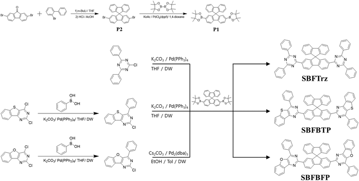
To improve the electron mobility and stability of the electron transport materials, a spirobifluorene core was substituted with several stable electron transport type units of 2,4-diphenyl-1,3,5-triazine, 4-phenylbenzo[4,5]thieno[3,2-d]pyrimidine and 4-phenylbenzofuro[3,2-d]pyrimidine. Spirobifluorene is known to have good carrier transporting ability because of the planar fluorene moiety. The ETLs were designed to have extended conjugation from the fluorene to the electron transport units by symmetrically substituting them at the C2 and C7 positions of spirobifluorene. Three new ETL materials, SBFTrz, SBFBTP, and SBFBFP, were developed by coupling the electron transport units with the spirobifluorene core through the Suzuki–Miyaura coupling reaction. The synthesis scheme is described in Scheme 1.Firstly, density functional theory (DFT) calculations were implemented using the Gaussian 16 program to investigate energy levels and frontier orbital distributions. The HOMO and LUMO distributions were pictured using a B3LYP 6-31G* basis set and are presented in Fig. 1. The HOMOs were mainly located on the spirobifluorene core in all compounds, but the HOMOs of SBFBTP and SBFBFP were spread slightly over the benzothienopyrimidine and benzofuropyrimidine units, whereas the LUMOs of SBFBTP and SBFBFP were mostly dispersed over benzothienopyrimidine and benzofuropyrimidine units with little distribution on the spirobifluorene core. The LUMO of SBFTrz was dispersed on the spirobifluorene core and triazine moiety. The calculated HOMO and LUMO levels were relatively deep in SBFTrz due to the strongly electron deficient diphenyltriazine unit.
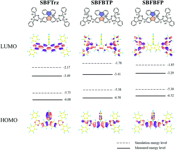 | ||
| Fig. 1 Optimized geometry and HOMO and LUMO distribution and energy levels of SBFTrz, SBFBTP and SBFBFP. | ||
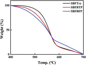
Thermal properties were estimated using a thermogravimetric analyzer (TGA) and differential scanning calorimeter (DSC). However, the glass transition temperature (Tg) of materials was not obtained during the heating cycles of DSC measurements. The thermal decomposition temperature (Td) which is the temperature at 5% weight loss was measured by TGA. The Tds of SBFTrz, SBFBTP and SBFBFP were measured to be 492, 467, and 439 °C, respectively, as shown in Fig. 2. The three electron transport materials showed high thermal stabilities of over 400 °C because of the robust spirobifluorene core and hydrogen bonding between the electron transport units and the spirobifluorene core.
The light absorption and emission of the materials were analyzed by ultraviolet-visible (UV-vis) absorption and photoluminescence (PL) measurements (Fig. 3). The absorption data were collected using a dilute tetrahydrofuran (THF) solution (1.0 × 10⁻⁵ M). The three materials showed absorption peaks below 380 nm assigned to the local absorption of the spirobifluorene core modified with the electron transport units. The absorption edge of the UV-vis spectra was also similar due to the same spirobifluorene core structure. The PL emission characteristics were measured for fluorescence and phosphorescence. The fluorescence wavelengths were gathered with the dilute THF solution at room temperature and the phosphorescence wavelengths were measured with the frozen THF solution after delay time of 1.2 ms. In all, the onset wavelengths of PL emission for SBFTrz, SBFBTP and SBFBFP were approximately 375 nm, indicating that the short wavelength emission comes from the same spirobifluorene core. However, the peak wavelengths of fluorescence were dissimilar, suggesting that the main emission is caused by the extended backbone structure. The red shift of the emission was observed in SBFBTP and SBFBFP due to the largely conjugated electron transport units. The triplet energy could be calculated from the phosphorescence onset wavelength. The triplet energies of SBFTrz, SBFBTP, and SBFBFP were 2.53, 2.43, and 2.47 eV, respectively, following the trend of the singlet energy in Table 1.
| λ abs (nm) | E S (eV) | E T (eV) | HOMO/LUMOa (eV) | HOMO/LUMOb (eV) | T d (°C) | |
|---|---|---|---|---|---|---|
| a DFT calculations with B3LYP 6-31G*. b Measured by cyclic voltammetry. c Onset wavelength of PL spectra in THF solution. d Onset wavelength of LTPL spectra in frozen THF. e LUMO: measured by cyclic voltammetry, HOMO: estimated from the equation EHOMO = ELUMO–EG. | ||||||
| SBFTrz | 388 | 3.31c | 2.53d | −5.75/−2.17 | −6.68e/−3.49 | 492 |
| SBFBTP | 391 | 3.30 | 2.43 | −5.38/−1.78 | −6.58/−3.41 | 467 |
| SBFBFP | 383 | 3.33 | 2.47 | −5.38/−1.85 | −6.52/−3.29 | 439 |
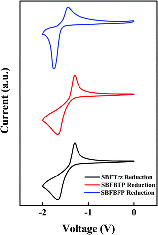
The HOMO and the LUMO were estimated using 0.1 M tetraethylammonium perchlorate solution with ferrocene as the reference material. As SBFTrz, SBFBTP and SBFBFP had strong electron deficient units, only the LUMO was measured. The HOMO was calculated using the LUMO and HOMO–LUMO gap from the UV-vis absorption edge. The cyclic voltammetry data are represented in Fig. 4. The HOMO and LUMO energy levels of SBFTrz, SBFBTP and SBFBFP were −6.68/−3.49, −6.58/−3.41, and −6.52/−3.29 eV, respectively. The HOMO and LUMO energy levels were deep due to the strong electron deficiency of the compounds. In Table 1, all photophysical, electrochemical and thermal property data of SBFTrz, SBFBTP and SBFBFP are represented.
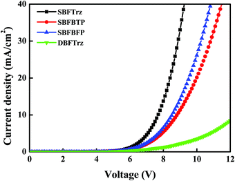
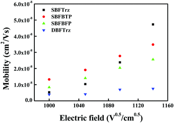
An electron only device (EOD) was fabricated to measure the electron transport abilities of the ETL materials. The 2,8-bis(4,6-diphenyl-1,3,5-triazin-2-yl)dibenzo-[b,d]furan (DBFTrz) electron transport material was utilized as a reference because it has good electron characteristics and has been actively used as an electron transport material. The electron current density data of the four materials are shown in Fig. 5. The electron current density of SBFTrz, SBFBTP, and SBFBFP was much higher than that of DBFTrz, and SBFTrz had the highest electron current density. The electron mobilities of these materials were also investigated with impedance measurements and a similar tendency was observed. As shown in Fig. 6, all new electron transport materials had higher mobilities than DBFTrz. In particular, the mobility of SBFTrz was increased dramatically at high electric fields. The fused structure of spirobifluorene and hydrogen bonding with the electron transport moieties maintained a planar geometry, inducing ordered intermolecular packing for improved electron mobilities.
In order to interpret the electron mobilities of SBFTrz, SBFBTP and SBFBFP, the molecular electrostatic potential was simulated. It was previously known that a low maximum negative electrostatic potential value is suitable for high electron mobility.27,28 A decrease in the absolute value of the electrostatic potential reduces the energy disorder of the given materials and thus increases the corresponding charge carrier mobility. The electrostatic potential map of materials calculated using DFT calculations and the Multiwfn program is represented in Fig. 7.29 The electrostatic potential energy values were −0.89 eV, −1.20 eV and −1.21 eV for SBFTrz, SBFBTP, and SBFBFP, respectively, suggesting that the mobility of SBFTrz would be higher than that of the others.
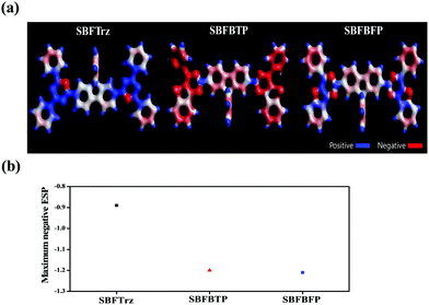 | ||
| Fig. 7 (a) Electrostatic potential map of SBFTrz, SBFBTP and SBFBFP (b) comparison of the maximum negative ESP of SBFTrz, SBFBTP and SBFBFP. | ||
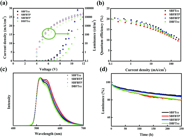
In order to evaluate the performances of the synthesized ETLs, multilayer PhOLEDs were developed based on the green phosphorescence emitter, tris(2-phenylpyridine)iridium(III) (Ir(ppy)3). In Fig. S1, (ESI†) the energy levels and chemical structures of the materials used for device fabrication are shown. The device evaluation was carried out with an optimized ETL thickness of 35 nm. The current density–voltage–luminance (J–V–L) data of the green PhOLEDs are shown in Fig. 8(a). The J of the devices at the same voltage was SBFTrz > SBFBTP ≈ SBFBFP > DBFTrz, agreeing with the tendency of electron mobilities. The L of the devices also followed the trend of the electron mobilities.
External quantum efficiency (EQE) plots against J are shown in Fig. 8(b). SBFTrz and SBFBFP devices showed slightly higher EQE than the DBFTrz device and SBFTrz in particular presented the highest EQE. The good electron transport properties of SBFTrz and SBFDBF promoted balancing of holes and electrons, which led to the improvement of the EQE with increased recombination efficiency. The relatively low EQE of the SBFBTP device might be owing to low triplet energy weakly quenching the triplet excitons. Additionally, the refractive index of the ETL materials can be regarded as one factor affecting the EQE. The refractive index measured on a spectroscopic ellipsometer was 1.81, 1.96, and 1.90 for SBFTrz, SBFBTP and SBFBFP, respectively, and these data are presented in Fig. 9. The EQE was high when a low refractive index ETL was used. The ETL is located between the EML and the metallic cathode. Accordingly, the organic layer that has the greatest influence on the surface plasmon polariton (SPP) is the ETL. It has been previously reported that the extent of the loss of the SPP mode is affected largely by the dielectric constant of the cathode and the electron transport layer.16,17,30,31 Therefore, the refractive index of the electron transport layer can be partially responsible for the outcoupling efficiency of the PhOLEDs. The EQE roll-off of the devices was slightly large in the SBFTrz device possibly due to the large change of the electron mobility according to the electric field.
The normalized electroluminescence (EL) spectra of the green PhOLEDs are in Fig. 8(c). All devices showed a main emission peak at 510 nm and a shoulder peak by Ir(ppy)3 emission, but the relative intensity of the shoulder peak was different. The intensity of the shoulder peak was in the order of SBFBTP (2.43 eV) > SBFBFP (2.47 eV) > SBFTrz (2.53 eV) > DBFTrz (2.94 eV), following the order of the triplet energies of ETLs.26 This indicates that the EL spectra are correlated with the triplet exciton quenching of Ir(ppy)3 by the ETL materials. The main emission is quenched by low triplet energy ETLs, which resulted in the relatively strong shoulder peak in the normalized EL spectra. The SBFBTP device with the lowest triplet energy showed the largest shoulder peak in the EL spectrum.
The device lifetime was measured at 3000 cd m−2 and is presented in Fig. 8(d). The SBFTrz and SBFBFP devices showed longer lifetimes than the DBFTrz device. The lifetime of up to 90% of initial luminance (LT90) was doubled by introducing SBFTrz and SBFBFP instead of DBFTrz. This can be explained by the electron stability of the ETL materials as can be justified by the voltage increase of the EOD according to the driving time at a constant current density. A constant electron current density of 10 mA cm−2 was applied to the EOD and Fig. 10 shows the voltage change of the EOD. SBFTrz showed the best electron stability among the ETLs, while DBFTrz exhibited the worst electron stability. All device data are organized in Table 2.
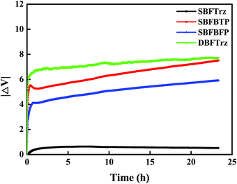 | ||
| Fig. 10 Voltage increase of the electron only devices of the ETLs according to electron stress time. | ||
| Device | V d (V)a | EQEb (%) | PEc (lm W−1) | CEd (cd A−1) | Color coordinate | |||
|---|---|---|---|---|---|---|---|---|
| [3000 cd m−2] | [Max] | [3000 cd m−2] | [Max] | [3000 cd m−2] | [Max] | |||
| a Driving voltage at 3000 cd m−2. b External quantum efficiency. c Power efficiency. d Current efficiency. | ||||||||
| SBFTrz | 7.7 | 18.3 | 20.5 | 26.6 | 49.3 | 65.5 | 73.5 | (0.31, 0.62) |
| SBFBTP | 8.2 | 16.4 | 19.2 | 22.6 | 51.8 | 58.5 | 68.8 | (0.33, 0.61) |
| SBFBFP | 8.0 | 17.7 | 20.5 | 24.7 | 53.1 | 63.2 | 73.6 | (0.32, 0.62) |
| DBFTrz | 9.1 | 17.0 | 20.3 | 21.1 | 57.9 | 60.9 | 83.0 | (0.30, 0.63) |
Conclusions
Spirobifluorene cored ETL materials modified with diphenyltriazine, benzothienopyrimidine and benzofuropyrimidine were developed as high mobility and stable ETLs. Compared with the DBFTrz ETL, the diphenyltriazine based SBFTrz and benzofuropyrimidine derived SBFBFP provided low driving voltage, high EQE and extended device lifetime. The great potential of spirobifluorene as an ETL core and diphenyltriazine and benzofuropyrimidine as an electron transport unit was confirmed.Experimental section
Synthetic details are provided in the ESI.†Device fabrication
The EOD was fabricated using a multilayer device structure: ITO (50 nm)/PEDOT![[thin space (1/6-em)]](https://www.rsc.org/images/entities/char_2009.gif) :
:![[thin space (1/6-em)]](https://www.rsc.org/images/entities/char_2009.gif) PSS (60 nm)/TSPO1 (10 nm)/ETL (50 nm)/LiF (1.5 nm)/Al (200 nm), where ITO is indium tin oxide, PEDOT
PSS (60 nm)/TSPO1 (10 nm)/ETL (50 nm)/LiF (1.5 nm)/Al (200 nm), where ITO is indium tin oxide, PEDOT![[thin space (1/6-em)]](https://www.rsc.org/images/entities/char_2009.gif) :
:![[thin space (1/6-em)]](https://www.rsc.org/images/entities/char_2009.gif) PSS is poly(3,4-ethylenedioxythiophene)
PSS is poly(3,4-ethylenedioxythiophene)![[thin space (1/6-em)]](https://www.rsc.org/images/entities/char_2009.gif) :
:![[thin space (1/6-em)]](https://www.rsc.org/images/entities/char_2009.gif) polystyrenesulfonate, TSPO1 is diphenyl[4-(triphenylsilyl)phenyl]phosphine oxide, and LiF is lithium fluoride. The fabricated device of the green PhOLEDs had a multilayer structure: ITO (50 nm)/DNTPD (60 nm)/BCFN (20 nm)/PCzAc (10 nm)/PBICT
polystyrenesulfonate, TSPO1 is diphenyl[4-(triphenylsilyl)phenyl]phosphine oxide, and LiF is lithium fluoride. The fabricated device of the green PhOLEDs had a multilayer structure: ITO (50 nm)/DNTPD (60 nm)/BCFN (20 nm)/PCzAc (10 nm)/PBICT![[thin space (1/6-em)]](https://www.rsc.org/images/entities/char_2009.gif) :
:![[thin space (1/6-em)]](https://www.rsc.org/images/entities/char_2009.gif) DBTTP1
DBTTP1![[thin space (1/6-em)]](https://www.rsc.org/images/entities/char_2009.gif) :
:![[thin space (1/6-em)]](https://www.rsc.org/images/entities/char_2009.gif) Ir(ppy)3 (30 nm, 25
Ir(ppy)3 (30 nm, 25![[thin space (1/6-em)]](https://www.rsc.org/images/entities/char_2009.gif) :
:![[thin space (1/6-em)]](https://www.rsc.org/images/entities/char_2009.gif) 75, 5% doping)/ETL (35 nm)/LiF (1.5 nm)/Al (200 nm), where DNTPD is N,N′-diphenyl-N,N′-bis-[4-(phenyl-m-tolyl-amino)-phenyl]-biphenyl-4,4′-diamine, BCFN is N-([1,1′-biphenyl]-4-yl)-9,9-dimethyl-N-(4-(9-phenyl-9H-carbazol-3-yl)phenyl)-9H-fluoren-2-amine, PCzAc is 9,9-dimethyl-10-(9-phenyl-9H-carbazol-2-yl)-9,10-dihydro-acridine, PBICT is 2-phenyl-4,6-bis(12-phenylindolo[2,3-a]carbazole-11-yl)-1,3,5-triazine and DBTTP1 is 4-(3-(triphenylen-2-yl)phenyl)dibenzo[b,d]thiophene. Fabrication of the device was executed by vacuum thermal evaporation at 5 × 10⁻⁷ torr. The device performance measurement was carried out using a Keithley 2400 source meter and a CS 2000 (Konica Minolta Inc.). The measurement of the device lifetime was performed using Polaronix (McScience Co.) lifetime test equipment under dark conditions with a Si photodiode detector and electrical source under constant driving current conditions.
75, 5% doping)/ETL (35 nm)/LiF (1.5 nm)/Al (200 nm), where DNTPD is N,N′-diphenyl-N,N′-bis-[4-(phenyl-m-tolyl-amino)-phenyl]-biphenyl-4,4′-diamine, BCFN is N-([1,1′-biphenyl]-4-yl)-9,9-dimethyl-N-(4-(9-phenyl-9H-carbazol-3-yl)phenyl)-9H-fluoren-2-amine, PCzAc is 9,9-dimethyl-10-(9-phenyl-9H-carbazol-2-yl)-9,10-dihydro-acridine, PBICT is 2-phenyl-4,6-bis(12-phenylindolo[2,3-a]carbazole-11-yl)-1,3,5-triazine and DBTTP1 is 4-(3-(triphenylen-2-yl)phenyl)dibenzo[b,d]thiophene. Fabrication of the device was executed by vacuum thermal evaporation at 5 × 10⁻⁷ torr. The device performance measurement was carried out using a Keithley 2400 source meter and a CS 2000 (Konica Minolta Inc.). The measurement of the device lifetime was performed using Polaronix (McScience Co.) lifetime test equipment under dark conditions with a Si photodiode detector and electrical source under constant driving current conditions.
Conflicts of interest
There are no conflicts to declare.Acknowledgements
This work was supported by MOTIE (20012622).References
- B. Geffroy, P. Le Roy and C. Prat, Organic light-emitting diode (OLED) technology: materials, devices and display technologies, Polym. Int., 2006, 55, 572–582 CrossRef CAS.
- S. Negi, P. Mittal and B. Kumar, Impact of different layers on performance of OLED, Microsyst. Technol., 2018, 24, 4981–4989 CrossRef CAS.
- C. Wu, C. Wu, J. Sturm and A. Kahn, Surface modification of indium tin oxide by plasma treatment: An effective method to improve the efficiency, brightness, and reliability of organic light emitting devices, Appl. Phys. Lett., 1997, 70, 1348–1350 CrossRef CAS.
- J. Kim, F. Cacialli, A. Cola, G. Gigli and R. Cingolani, Increase of charge carriers density and reduction of Hall mobilities in oxygen-plasma treated indium–tin–oxide anodes, Appl. Phys. Lett., 1999, 75, 19–21 CrossRef CAS.
- L. Hung, C. W. Tang and M. G. Mason, Enhanced electron injection in organic electroluminescence devices using an Al/LiF electrode, Appl. Phys. Lett., 1997, 70, 152–154 CrossRef CAS.
- X. Zhou, M. Pfeiffer, J. Blochwitz, A. Werner, A. Nollau, T. Fritz and K. Leo, Very-low-operating-voltage organic light-emitting diodes using AP-doped amorphous hole injection layer, Appl. Phys. Lett., 2001, 78, 410–412 CrossRef CAS.
- G. Malliaras and J. Scott, The roles of injection and mobility in organic light emitting diodes, J. Appl. Phys., 1998, 83, 5399–5403 CrossRef CAS.
- J. Y. Lee, Mixed-host-emitting layer for high-efficiency organic light-emitting diodes, J. Inf. Disp., 2014, 15, 139–144 CrossRef CAS.
- N. C. Erickson and R. J. Holmes, Investigating the Role of Emissive Layer Architecture on the Exciton Recombination Zone in Organic Light-Emitting Devices, Adv. Funct. Mater., 2013, 23, 5190–5198 CrossRef CAS.
- N. Liu, S. Mei, D. Sun, W. Shi, J. Feng, Y. Zhou, F. Mei, J. Xu, Y. Jiang and X. Cao, Effects of charge transport materials on blue fluorescent organic light-emitting diodes with a host-dopant system, Micromachines, 2019, 10, 344 CrossRef PubMed.
- C. Giebeler, H. Antoniadis, D. D. Bradley and Y. Shirota, Influence of the hole transport layer on the performance of organic light-emitting diodes, J. Appl. Phys., 1999, 85, 608–615 CrossRef CAS.
- K. Goushi, R. Kwong, J. J. Brown, H. Sasabe and C. Adachi, Triplet exciton confinement and unconfinement by adjacent hole-transport layers, J. Appl. Phys., 2004, 95, 7798–7802 CrossRef CAS.
- D. Y. Kondakov, Role of chemical reactions of arylamine hole transport materials in operational degradation of organic light-emitting diodes, J. Appl. Phys., 2008, 104, 084520 CrossRef.
- A. P. Kulkarni, C. J. Tonzola, A. Babel and S. A. Jenekhe, Electron transport materials for organic light-emitting diodes, Chem. Mater., 2004, 16, 4556–4573 CrossRef CAS.
- Y. Wang, J. H. Yun, L. Wang and J. Y. Lee, High triplet energy hosts for blue organic light-emitting diodes, Adv. Funct. Mater., 2021, 31, 2008332 CrossRef CAS.
- A. Salehi, S. Ho, Y. Chen, C. Peng, H. Yersin and F. So, Highly efficient organic light-emitting diode using a low refractive index electron transport layer, Adv. Opt. Mater., 2017, 5, 1700197 CrossRef.
- H. Shin, J. H. Lee, C. K. Moon, J. S. Huh, B. Sim and J. J. Kim, Sky-blue phosphorescent OLEDs with 34.1% external quantum efficiency using a low refractive index electron transporting layer, Adv. Mater., 2016, 28, 4920–4925 CrossRef CAS PubMed.
- X.-B. Shi, C.-H. Gao, D.-Y. Zhou, M. Qian, Z.-K. Wang, L.-S. Liao and L.-S. Liao, Surface plasmon polariton enhancement in blue organic light-emitting diode: role of metallic cathode, Appl. Phys. Express, 2012, 5, 102102 CrossRef.
- C. L. Chiang, S. M. Tseng, C. T. Chen, C. P. Hsu and C. F. Shu, Influence of molecular dipoles on the photoluminescence and electroluminescence of dipolar spirobifluorenes, Adv. Funct. Mater., 2008, 18, 248–257 CrossRef CAS.
- H. Etori, X. L. Jin, T. Yasuda, S. Mataka and T. Tsutsui, Spirobifluorene derivatives for ultraviolet organic light-emitting diodes, Synth. Met., 2006, 156, 1090–1096 CrossRef CAS.
- Y.-L. Liao, W.-Y. Hung, T.-H. Hou, C.-Y. Lin and K.-T. Wong, Hole mobilities of 2,7-and 2,2′-disubstituted 9,9′-spirobifluorene-based triaryldiamines and their application as hole transport materials in OLEDs, Chem. Mater., 2007, 19, 6350–6357 CrossRef CAS.
- N. Cocherel, C. Poriel, J. Rault-Berthelot, F. Barrière, N. Audebrand, A. M. Slawin and L. Vignau, New 3π-2Spiro Ladder-Type Phenylene Materials: Synthesis, Physicochemical Properties and Applications in OLEDs, Chem. – Eur. J., 2008, 14, 11328–11342 CrossRef CAS PubMed.
- N. Rehmann, D. Hertel, K. Meerholz, H. Becker and S. Heun, Highly efficient solution-processed phosphorescent multilayer organic light-emitting diodes based on small-molecule hosts, Appl. Phys. Lett., 2007, 91, 103507 CrossRef.
- Q. Li, H. Liu, W. Sun, S. Wang, X. Dong, L. Wang and X. Li, Hole-transporting material based on spirobifluorene unit with perfect amorphous and high stability for efficient OLEDs, J. Mater. Sci.: Mater. Electron., 2019, 30, 11440–11450 CrossRef CAS.
- R. Braveenth, H. W. Bae, Q. P. B. Nguyen, H. M. Ko, C. H. Lee, H. J. Kim, J. H. Kwon and K. Y. Chai, Spirobifluorene core-based novel hole transporting materials for red phosphorescence OLEDs, Molecules, 2017, 22, 464 CrossRef PubMed.
- Y. J. Kang and J. Y. Lee, High triplet energy electron transport type exciton blocking materials for stable blue phosphorescent organic light-emitting diodes, Org. Electron., 2016, 32, 109–114 CrossRef CAS.
- R. A. Marcus, Electron transfer reactions in chemistry. Theory and experiment, Rev. Mod. Phys., 1993, 65, 599 CrossRef CAS.
- G. W. Kim, Y. H. Son, H. I. Yang, J. H. Park, I. J. Ko, R. Lampande, J. Sakong, M.-J. Maeng, J.-A. Hong and J. Y. Lee, Diphenanthroline electron transport materials for the efficient charge generation unit in tandem organic light-emitting diodes, Chem. Mater., 2017, 29, 8299–8312 CrossRef CAS.
- T. Lu and F. Chen, Multiwfn: a multifunctional wavefunction analyzer, J. Comput. Chem., 2012, 33, 580–592 CrossRef CAS PubMed.
- A. Salehi, Y. Chen, X. Fu, C. Peng and F. So, Manipulating refractive index in organic light-emitting diodes, ACS Appl. Mater. Interfaces, 2018, 10, 9595–9601 CrossRef CAS PubMed.
- J. Lee, J. Song, J. Park and S. Yoo, Toward Ultra-Efficient OLEDs: Approaches Based on Low Refractive Index Materials, Adv. Opt. Mater., 2021, 2002182 CrossRef CAS.
Footnote |
| † Electronic supplementary information (ESI) available. See DOI: 10.1039/d1qm01610e |
| This journal is © the Partner Organisations 2022 |

