 Open Access Article
Creative Commons Attribution 3.0 Unported Licence
Enhanced FTIR bench-top imaging of single biological cells
C.
Hughes
ab,
A.
Henderson
a,
M.
Kansiz
c,
K. M.
Dorling
d,
M.
Jimenez-Hernandez
ab,
M. D.
Brown
b,
N. W.
Clarke
be and
P.
Gardner
*a
aManchester Institute of Biotechnology, The University of Manchester, 131 Princess Street, Manchester, M1 7DN, UK. E-mail: peter.gardner@manchester.ac.uk
bGenito Urinary Cancer Research Group, Institute of Cancer Sciences, Paterson Building, The University of Manchester, Manchester Academic Health Science Centre, The Christie NHS Foundation Trust, Manchester, M20 4BX, UK
cAgilent Technologies Australia Pty Ltd, 679 Springvale Rd, Mulgrave, VIC. 3179, Australia
dAgilent Technologies, 5500 Lakeside, Cheadle, Cheshire, SK8 3GR, UK
eDepartment of Urology, The Christie NHS Foundation Trust, Manchester, M20 4BX, UK
First published on 20th February 2015
Abstract
A new optical system has recently been developed that enables infrared images to be obtained with a pixel resolution of 1 micron on a bench-top instrument using a thermal source. We present here imaging data from two contrasting cellular systems that represent different challenges. Renal carcinoma cells cytospun onto CaF2 have a largely rounded morphology and thus suffer from strong resonant Mie scattering. Skin fibroblast cells, cultured onto CaF2 on the other hand are very spread out so scatter less strongly but are so thin they deliver extremely weak signals. Using suitable pre-processing methods, including PCA noise reduction and RMieS correction, we demonstrate that useful high resolution images can be obtained from either sample.
The use of FTIR for investigating global chemistry changes at the single cell level is a well-established method of analysis. Many studies, for example, have sought to understand and model drug–cell interactions, with the eventual aim of achieving methods for high-throughput pharmaceutical screening.1–4 Historically, many of these studies have been conducted using synchrotron radiation sources, rather than using the standard bench-top globar. This was due to the additional brightness advantage of a synchrotron, allowing bio-spectroscopists to probe the infrared signatures of individual cells using small apertures, whilst maintaining a relatively good signal to noise ratio.5
In terms of being able to spatially resolve intra-cellular chemical changes in a cell, one approach is synchrotron-based point-by-point mapping. This involves the use of a single element detector and sampling aperture of ∼7–12 μm. The stage is moved with a ∼3–6 μm step size, leading to extremely time-consuming, low-throughput spectral acquisitions.6
Due to the emergence of commercially available Focal Plane Array (FPA) detectors, it has been possible to capture multiple cells simultaneously, enabling high-throughput and spatially-resolved cellular imaging.
The most advanced focal plane array setup with a synchrotron-source in terms of spatial resolution was developed at the IRENI beamline (Synchrotron Radiation Center, WI, USA). This unique beamline, which combined 12 separate SRIR beams, enabled diffraction-limited imaging with a focal plane array detector using a pixel size of ∼0.5 μm.7,8 Until now most bench-top imaging systems generally use either 6.25 μm or 5.5 μm for linear array and focal plane array detectors respectively. Higher pixel resolution (magnification) optics have been available but poor coupling, typically due to the use of non-customised objectives, have generally resulted in extremely poor SNR making them unsuitable for routine applications. Due to a new microscope design, it is now possible to change the configuration for enhanced magnification (5× increase), achieving a pixel resolution of ∼1.1 μm (compared to the standard 5.5 μm pixel size) through an automated software initiated optics change within the microscope body (proprietary to Agilent Technologies) and not by changing the objective, thereby also retaining the full 21 mm working distance of the N.A. = 0.62 15× objective.
In order to test the capabilities of this new system for the analysis of single eukaryotic cells we have imaged two cellular systems that offer two different challenges namely highly scattering and low signal absorbance.
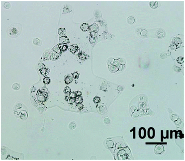
For an example of a highly scattering sample, the cell line used was ‘2245R’, originally established from primary kidney resection from a patient with confirmed clear-cell renal carcinoma at the N.C.I., U.S.A.9 In our experience, this particular subtype of renal carcinoma cells have relatively low absorbance values compared to cells from other tumour cells from different organ origins, presumably due to the cells being inherently thin. Importantly the cells also tend to have a rounded morphology (see Fig. 1) and thus spectra suffer significantly from resonant Mie scattering. The cell line 2245R, therefore, represents a challenging sample with a realistic demonstration of achievable signal to noise in both magnification modes using relatively conservative parameter selections.
Formalin fixed 2245R cells were washed with Hank's balanced salt solution (HBSS) (6 × 1 mL) to wash away any residual phosphate ions prior to cyto-spinning onto calcium fluoride (CaF2) slides. Finally the slides were washed with double distilled water and air dried for at least 24 hours prior to data collection.3
In both magnification modes, transmission images were captured using an Agilent Cary 670-IR spectrometer coupled with a Cary 620-IR imaging microscope (Agilent Technologies, CA) with a 128 × 128 MCT FPA detector. A 15× objective (and condenser) with a numerical aperture of 0.62 was used in both modes.
Spectra were collected at a spectral resolution of 4 cm−1 and a zero-filling factor to give a spectral data point spacing of 2 cm−1. 256 and 128 co-added scans were used for background and sample respectively. Using these parameters, it took approximately 8 minutes (prior to FT processing) to capture one sample image for a 700 × 700 μm area (1 tile) at 5.5 μm pixel resolution. For the high magnification (1.1 μm pixel resolution, a region of 140 μm × 140 μm is sampled in comparison to the conventional setup. In order, therefore, to cover the same total region (700 × 700 μm), a 5 × 5 image mosaic was acquired with an acquisition time of 200 minutes (prior to FT processing). The Blackmann–Harris 4-term apodization function was used for all processing.
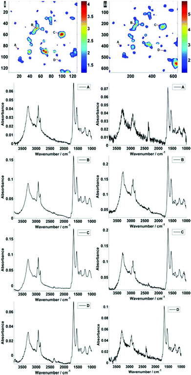
Fig. 2 displays the region of interest (Fig. 1) sampled by the two configurations; conventional (i) and high magnification (ii). The chemical maps are amide I peak area integrals. Non-cell related pixel spectra have been removed using an amide I peak area threshold of 0.177. Individual pixel spectra representing a sample from approximately the same region were selected for comparison. Regions A + D are typical of single cell spectra while B + C are from cellular clumps, giving rise to an overall increase in absorbance and therefore signal to noise ratio.
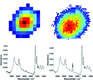
For further discussion on signal to noise, one individual single cell was isolated from each map (Fig. 3). The SNR was calculated for the corresponding individual pixel spectra of the cell. The signal (the amide I peak height) was ratioed against rms (calculated at the 99% confidence level using min and max values of absorbance across the range of 2000–2200 cm−1).
Mean SNR values were 60 and 42 for low- and high-magnification (of 63 and 905 spectra respectively) modes. When the cell spectra are averaged, creating one representative spectrum of global cell chemistry, the SNR values increased to 167 (low mag.) and 153 (high mag.) respectively. The high mag. data benefitted from the higher proportion of individual pixel spectra (and a % increase in SNR of 264% compared to 178%). N.B. While this example cannot be completely conclusive due to possible differences in purge conditions during acquisition of the separate images, it does serve as a rule of thumb figure for comparison.
It is clear that while there is an increased cost penalty in acquisition time to sample the equivalent region with high magnification, the difference in signal to noise is not too dissimilar if the objective of the experiment is to acquire a mean spectrum, representing the overall biochemistry of individual cells and the investigator is not interested in sub-cellular imaging.
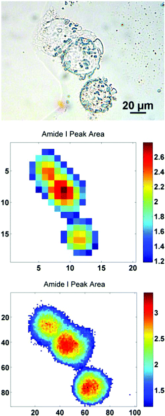
A major benefit of the high magnification mode is the increase in accuracy of the spectral profile of an individual cell. This is due to a reduction in pixel mixing of cellular spectral profiles. Pixel mixing, at a pixel resolution of 5.5 μm, will inevitably lead to the contamination of cellular IR signatures as a consequence of sub-cellular boundaries and inter-cellular boundaries in instances of clumped cells. This could cause issues if the neighbouring cells are in different cell cycle phases or have responded differently to chemical agents.10
In order to further illustrate this point, a sub-region from the original images has been highlighted. The region contains just three biological cells (Fig. 4), covering an area of 91 × 101 pixels in the high mag. image (∼100 × 111 μm). Increasing the magnification such that there is some degree of spatial over-sampling relative to the probe wavelengths has clearly resulted in more accurate spectral images from the individual cells. The top two cells that are clumped together, previously un-resolvable in the standard magnification setup, now have clear boundaries containing regional maxima of their respective amide I peak area. The IR chemimaps presented in Fig. 4 are based upon the raw collected data and have not been subject to any pre-processing. At this stage the amide I map predominantly reflects the morphology of the cells with high intensity representing the thicker part of the cells.
For further enhancement, the high-magnification image was subject to processing with a principal component analysis noise reduction algorithm by retaining 50 of the total principal components11 (Fig. 5).
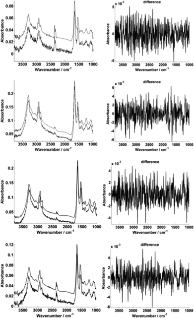
Fig. 5 displays the raw and noise-reduced representative spectra A–D from Fig. 2 respectively, including the residual differences; the use of such an algorithm should be subject to checks to ensure that no true biological information has been lost, i.e. the residual differences should reflect signals that are not representative of a biological spectral profile.
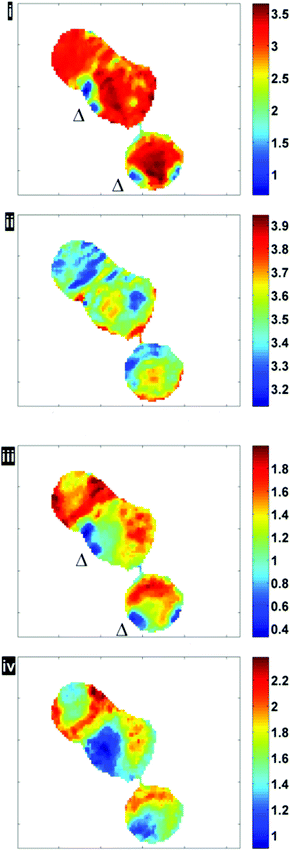
Fig. 6 illustrates the importance of applying the RMieS-EMSC correction using two integrated spectral ranges covering regions largely related to protein (1597–1738 cm−1) and lipid (2800–3000 cm−1). Fig. 6i displays the noise-reduced amide I peak area map that has been vector normalised, which has a dramatically different contrast compared to Fig. 4. Without normalisation, the chemical images are generally displaying information due to thickness differences, coupled with resonant Mie scattering12 in the cell (Fig. 4). When thickness differences have been reduced through normalisation, the RMie scattering distortions are particularly evident due to spherical particles that are in large contrast to the remainder of the cells in the non scatter-corrected images for both amide I and lipid peak areas in Fig. 6i and 6iii (indicated by Δ). Once the RMieS-EMSC correction is applied the spherical particles outlined by a difference in contrast disappear from the chemimap (Fig. 6ii and iv). With reference to the optical image (Fig. 4), these spherical particles are most likely to be nucleoli, as the cyto-spin technique is known to accentuate segmentation in the nucleus, distorting the nuclear morphology so that nucleoli appear more prominent.
Fig. 7 illustrates the difference before and after RMieS-EMSC correction in different regions of each cell using k-means clustering. Unsurprisingly, the regions that display the sphere-like objects (coloured red) in the raw image display the most severe scatter distortion in the mean representative spectrum. Note that the spectrum is characteristic of an IR signature of biological origin and therefore it is unlikely for the objects to be sample preparation artefacts. Once the correction has been applied, the differences in spectral signatures from the different cellular regions are much more subtle.
 | ||
| Fig. 7 Pseudo-colour k-means cluster maps and mean spectra for 3 classes, displaying different general regions before (i, ii) and after RMieS-EMSC correction (iii, iv). | ||
Prior to the realisation of high-resolution capability on a bench-top instrument, the cyto-spin technique was useful in order to image a large number of cell spectra simultaneously. A common approach was to identify the pixel spectra belonging to a single cell and to take the average, thus gaining a significant enhancement in signal![[thin space (1/6-em)]](https://www.rsc.org/images/entities/char_2009.gif) :
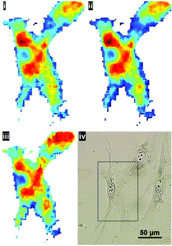
:![[thin space (1/6-em)]](https://www.rsc.org/images/entities/char_2009.gif) noise in the resulting representative cell spectrum (akin to ‘single point mode’ at a synchrotron IR beamline). This method of sample preparation is appropriate if the aim is to capture the global signature of the cell as a whole. The higher magnification mode may be useful to resolve cell–cell boundaries, however, even after pre-processing, the cyto-spin technique is not appropriate for evaluating spatially-localised chemical differences. In the latter case, cells are typically grown directly onto the IR substrate. To illustrate the benefits of the enhanced resolution using a sample prepared in such a way, human skin fibroblasts, cultured directly onto the CaF2 substrate, were chosen to illustrate the potential for imaging localised chemical activity. Spectra were collected at a spectral resolution of 16 cm−1 and a zero-filling factor to give a spectral data point spacing of 2 cm−1. 512 co-added scans were used for background and sample respectively. Fig. 8 displays the lipid integration map during various stages of processing: (i) vector normalised, (ii) noise-reduced (50 PCs) and vector normalised (iii) noise reduced, RMieS-EMSC corrected and vector normalised. Using the stated collection parameters, there is not a great deal of difference between all three maps in terms of noise, however in Fig. 8iii it can be seen that certain features are resolvable which were previously hidden before RMieS-EMSC correction, underlying the importance of applying some scatter-correction despite the sample being relatively flat.
noise in the resulting representative cell spectrum (akin to ‘single point mode’ at a synchrotron IR beamline). This method of sample preparation is appropriate if the aim is to capture the global signature of the cell as a whole. The higher magnification mode may be useful to resolve cell–cell boundaries, however, even after pre-processing, the cyto-spin technique is not appropriate for evaluating spatially-localised chemical differences. In the latter case, cells are typically grown directly onto the IR substrate. To illustrate the benefits of the enhanced resolution using a sample prepared in such a way, human skin fibroblasts, cultured directly onto the CaF2 substrate, were chosen to illustrate the potential for imaging localised chemical activity. Spectra were collected at a spectral resolution of 16 cm−1 and a zero-filling factor to give a spectral data point spacing of 2 cm−1. 512 co-added scans were used for background and sample respectively. Fig. 8 displays the lipid integration map during various stages of processing: (i) vector normalised, (ii) noise-reduced (50 PCs) and vector normalised (iii) noise reduced, RMieS-EMSC corrected and vector normalised. Using the stated collection parameters, there is not a great deal of difference between all three maps in terms of noise, however in Fig. 8iii it can be seen that certain features are resolvable which were previously hidden before RMieS-EMSC correction, underlying the importance of applying some scatter-correction despite the sample being relatively flat.
The increased lipid chemistry both in the nuclear region and the fibroblast lamellipodia can be resolved. In addition, the fact that multiple cells are present in the image may have been lost without the 1.1 μm pixel resolution.
Conclusions
The examples described here were a result of a moderate proportion of co-added scans, with a strategy for improving signal to noise post-acquisition.A major benefit of using the new high-magnification system will be for application in single cell analysis, as the 1 micron per pixel advantage will mean that it will be more viable to track biochemical changes across cells without the practical and economic expense of synchrotron measurements.
The possibility to obtain ultra-high spatial resolution FTIR images is an important turning-point in pushing the diffraction limited spatial resolution of bench-top systems.
Acknowledgements
This work was funded by the UK's Engineering and Physical Sciences Research Council on grant number EP/I027440/1.Notes and references
- A. Derenne, R. Gasper and E. Goormaghtigh, Analyst, 2011, 136, 1134–1141 RSC.
- K. R. Flower, I. Khalifa, P. Bassan, D. Démoulin, E. Jackson, N. P. Lockyer, A. T. McGown, P. Miles, L. Vaccari and P. Gardner, Analyst, 2011, 136, 498–507 RSC.
- M. Jimenez-Hernandez, C. Hughes, P. Bassan, F. Ball, M. D. Brown, N. W. Clarke and P. Gardner, Analyst, 2013, 138, 3957–3966 RSC.
- A. V. Rutter, M. R. Siddique, J. Filik, C. Sandt, P. Dumas, G. Cinque, G. D. Sockalingum, Y. Yang and J. Sulé-Suso, Cytometry Part A, 2014, 85, 688–697 CrossRef PubMed.
- P. Dumas, F. Polack, B. Lagarde, O. Chubar, J. L. Giorgetta and S. Lefrançois, Infrared Phys. Technol., 2006, 49, 152–160 CAS.
- E. Gazi, J. Dwyer, N. P. Lockyer, J. Miyan, P. Gardner, C. A. Hart, M. D. Brown and N. W. Clarke, Vib. Spectrosc., 2005, 38, 193–201 CrossRef CAS PubMed.
- C. J. Hirschmugl and K. M. Gough, Appl. Spectrosc., 2012, 66, 475–491 CrossRef CAS PubMed.
- J. Sedlmair, M. Unger, B. Illman and C. Hirschmugl, Microsc. Microanal., 2012, 18, 840–841 CrossRef.
- C. Hughes, M. Liew, A. Sachdeva, P. Bassan, P. Dumas, C. A. Hart, M. D. Brown, N. W. Clarke and P. Gardner, Analyst, 2010, 135, 3133–3141 RSC.
- C. Hughes, M. D. Brown, N. W. Clarke, K. R. Flower and P. Gardner, Analyst, 2012, 137, 4720–4726 RSC.
- R. Bhargava, S. Q. Wang and J. L. Koenig, Appl. Spectrosc., 2000, 54, 1690–1706 CrossRef CAS.
- P. Bassan, A. Kohler, H. Martens, J. Lee, H. J. Byrne, P. Dumas, E. Gazi, M. Brown, N. Clarke and P. Gardner, Analyst, 2010, 135, 268–277 RSC.
| This journal is © The Royal Society of Chemistry 2015 |

