 Open Access Article
Creative Commons Attribution 3.0 Unported Licence
Processing polymer photocatalysts for photocatalytic hydrogen evolution
Richard Jack
Lyons
 a and
Reiner Sebastian
Sprick
 *b
*b
aDepartment of Chemistry and Materials Innovation Factory, University of Liverpool, Liverpool L7 3NY, UK
bDepartment of Pure and Applied Chemistry, University of Strathclyde, Glasgow G1 1XL, UK. E-mail: sebastian.sprick@strath.ac.uk
First published on 10th June 2024
Abstract
Conjugated materials have emerged as competitive photocatalysts for the production of sustainable hydrogen from water over the last decade. Interest in these polymer photocatalysts stems from the relative ease to tune their electronic properties through molecular engineering, and their potentially low cost. However, most polymer photocatalysts have only been utilised in rudimentary suspension-based photocatalytic reactors, which are not scalable as these systems can suffer from significant optical losses and often require constant agitation to maintain the suspension. Here, we will explore research performed to utilise polymeric photocatalysts in more sophisticated systems, such as films or as nanoparticulate suspensions, which can enhance photocatalytic performance or act as a demonstration of how the polymer can be scaled for real-world applications. We will also discuss how the systems were prepared and consider both the benefits and drawbacks of each system before concluding with an outlook on the field of processable polymer photocatalysts.
Wider impactThe study of photocatalytic nanoparticles, nanofibers, and films for photocatalytic hydrogen evolution will be of benefit for the development of other photocatalytic systems such as oxygen evolution, hydrogen peroxide formation, and organic transformation. Furthermore, they could provide mechanistic insight and greater understanding of polymer degradation pathways allowing for material engineering for more robust organic photocatalytic materials. |
1. Introduction
The finite availability of fossil fuels and growing climate emergency has resulted in the urgent need to develop alternative, scalable energy sources. Nearly inexhaustible solar energy is our best alternative to fossil fuels; however, the intermittency of sunlight due to the day/night cycle, the influence of weather conditions, and seasonal changes is problematic. Therefore, it is necessary to capture and store solar energy so it can be made available on demand. Hydrogen gas is one of the most promising forms of storage as it possesses the highest gravimetric energy density (∼120 MJ kg−1) of all known substances,1 it can be transported,2 and when consumed through combustion or in a hydrogen fuel cell yields only water as the by-product.3 Potentially, the conversion of solar energy into hydrogen is most conveniently performed via photocatalytic overall water splitting (OWS), in which a photocatalyst uses sunlight directly to split water into hydrogen and oxygen in a stoichiometric 2![[thin space (1/6-em)]](https://www.rsc.org/images/entities/char_2009.gif) :
:![[thin space (1/6-em)]](https://www.rsc.org/images/entities/char_2009.gif) 1 ratio (Knallgas).4
1 ratio (Knallgas).4
Generally, photocatalysis takes place via the following mechanism: (i) photoexcitation by light absorption, (ii) charge separation and migration of the charge carriers to active sites, and (iii) surface redox reactions (Fig. 1).5,6
 | ||
| Fig. 1 Fundamental processes involved in photocatalytic water splitting: (i) photoexcitation; (ii) charge separation and migration; and (iii) surface redox reactions at the relevant co-catalysts. Also depicted are the energy level alignment required to drive photocatalytic water splitting.7,8 IP: ionisation potential; EA: electron affinity; Eg: bandgap. The half-reactions and overall water splitting reaction equations are given on the right hand side. | ||
Photoexcitation occurs when a photon with energy equal to or greater than the bandgap is absorbed, promoting an electron from the valence band (VB) to the conduction band (CB).4 This forms a bound electron–hole pair which can dissociate into a free electron/electron–hole and migrate to the surface to drive redox reactions. For water splitting, protons are reduced by photoexcited electrons in the CB to form hydrogen, whilst water is oxidised by holes in the VB forming oxygen and protons (Fig. 1). OWS is a thermodynamically unfavourable process (ΔG = +237.14 kJ mol−1), therefore, a photocatalyst is required to have a theoretical minimum bandgap of 1.23 eV to drive the reaction.9 However, due to kinetic barriers and band-edge alignment requirements (Fig. 1), an overpotential is necessary, resulting in the actual minimum bandgap to be in excess of 1.8 eV (ca. 690 nm).9 Appropriate alignment of the CB minimum and the VB maximum, which are often equated to the electron affinity (EA) and ionisation potential (IP), respectively, is necessary to thermodynamically drive the redox reactions.7,10,11 To provide a thermodynamic driving force, the IP must be more positive than the oxidation potential of water (1.23 V vs. NHE, pH = 0), while the EA must be more negative than the reduction potential of protons (0 V vs. NHE, pH = 0; Fig. 1).10
Over a half-century has passed since the first report of photoelectrochemical hydrogen evolution from water using TiO2,12 and efforts since have, generally, focussed on inorganic photocatalysts for OWS.4,8 Impressive progress has been made since the initial report of TiO2 with examples such as SrTiO3:Al showing over 1000 hours of activity for OWS.13 Loading Rh/Cr2O3/CoOOH onto SrTiO3:Al resulted in a material that performs OWS with an external quantum efficiency (EQE) approaching unity, thus, nearly all incident photons in the 350–360 nm range are utilised to drive OWS.14 However, due to the large bandgap of SrTiO3:Al, absorption only occurs within the UV region and, consequently, only ca. 5% of available solar energy at ground level can be utilised (Fig. 2).15 This issue is common for inorganic photocatalysts due to their large bandgaps which greatly limits their potential for application in scale-up devices.16 More recently, however, a highly promising solar-to-hydrogen conversion efficiency (STH) of 9% was reported by Zhou et al. using Rh/Cr2O3/Co3O4–InGaN/GaN nanowires supported on silicon wafers.17 While this work provides an outstanding result it should be noted that an elevated temperature of 70 °C was necessary to reach this impressive STH which may limit real world utility.17
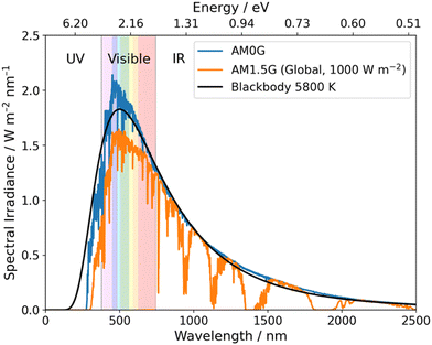 | ||
| Fig. 2 Blackbody irradiance curve at 5800 K and standard solar spectra for space (AM0G) and terrestrial (AM1.5G). Data obtained from ref. 18. | ||
Compared to inorganic materials, organic semiconductors (OSCs) typically possess narrower bandgaps and, therefore, allow for the utilisation of photons within the visible region (380–740 nm) which accounts for ca. 40% of the solar spectrum (Fig. 2).19 Yanagida et al. presented early examples of conjugated organic materials which could be used for sacrificial photocatalytic hydrogen evolution, these materials included: poly(p-phenylene),20 oligo(p-phenylene),21 and poly(pyridine-2,5-diyl).22,23 Despite that, these materials possessed relatively low hydrogen evolution rates (HERs) and organic semiconductor photocatalysts received little interest for almost two decades.
This changed after the first report of carbon nitrides (CNs) performing sacrificial hydrogen evolution by Wang et al. in 2009.24 Since this ground-breaking report, conjugated organic materials have received a renaissance owing to the synthetic control afforded by conjugated organic materials. This synthetic control allows for their properties, such as frontier energy levels, easy to modulate and can allow for simple processability.25 Some of the families of conjugated organic materials explored include: CNs,16 covalent organic frameworks (COFs),26,27 covalent triazine-based frameworks (CTFs),28 conjugated microporous polymers (CMPs),29 conjugated linear polymers,7 conjugated oligomers,21,30 and molecular photocatalysts.31–34 Many of these studies have successfully demonstrated the synthetic control afforded by organic structures. For example, modification of the conjugated backbone to form donor–acceptor type polymers with modified frontier energy levels, lower exciton binding energies, and improved charge separation;35–39 and planarization which facilitates improved charge mobility through the conjugated backbone.40,41 Molecular photocatalysts and linear conjugated polymers functionalised with solubilising flexible side-chains have been of particular interest due to the ease in which they can be processed into more sophisticated systems beyond relatively simple bulk suspension-based systems. Furthermore, functionalisation of side-chains has also been demonstrated as a route to enhance photocatalytic performance.42–46 However, while desirable, solubility is not always necessary for device fabrication.
The processing of photocatalytic materials should be driven by either the necessity to enhance photocatalytic efficiency, to improve reactor design, or, ideally, both. While photocatalyst efficiency is often considered the most important aspect, it is important to consider the end usage of the material and its applicability for real world applications. Processing opens avenues for improving efficiency in several ways, such as reducing particle sizes or forming heterostructures (vide infra). Furthermore, processing can increase the utility of photocatalysts by simplifying the reactor design or improving photocatalyst recyclability. The main classes of materials in which organic semiconductors have been processed into are photocatalytic nanoparticles (PNPs), nanosheets, nanofibers, and films (Fig. 3, all of which are described in greater detail within their relevant sections). Table 1 provides a summary of the length scales in each of the spatial dimensions of the material classes discussed herein.
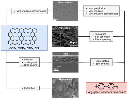 | ||
| Fig. 3 Representative micrographs of processed materials discussed herein, and the processing routes discussed within. Cryo-TEM image of nanoparticles (top). Adapted under CC-BY 4.0 License.47 Electrospun nanofibers of conjugated molecule/polymer (second from top). Adapted under CC-BY 4.0 License.48 Side on scanning electron micrograph of conjugated film on a glass substrate (second from bottom). Adapted with permission from ref. 49. Copyright 2020, The Royal Society of Chemistry. SEM images of exfoliated nanosheets (bottom). Adapted with permission from J. Am. Chem. Soc., 2023, 145, 12745–12754. Copyright 2023, American Chemical Society.50 | ||
| Material class | Spatial dimensions | ||
|---|---|---|---|
| X | Y | Z | |
| Nanoparticles | 10s–100s nm | 10s–100s nm | 10s–100s nm |
| Nano sheets | 10s nm | 100s nm | 100s nm |
| Nanofibers | 10s–100s nm | 10s–100s nm | nm–μm |
| Films | nm–μm | mm–m | mm–m |
There are two principal routes of processing organic photocatalysts into these materials: pre- and post-synthesis processing. Pre-synthesis processing is the use of confinement or templates to fabricate intricate systems before or during the creation of the photocatalyst, this is a bottom-up approach and is useful in processing insoluble materials such as insoluble linear polymers or CTFs. Whereas, post-synthesis processing relates to the processing after the photocatalyst has been prepared; this is a top-down approach. Post-synthesis processing is relatively simple provided that the materials are soluble – such as conjugated polymers with solubilising side-chains or molecular photocatalysts – and have been widely used to prepare photocatalytic nanoparticles (PNPs), nanofibers, and film-type devices. However, post-synthesis processing of insoluble materials into films-type devices can be performed by drop-casting/filtration or into nanosheets by exfoliation of layered photocatalysts. Due to the relative simplicity and availability of commercial materials, post-synthesis processing has been the dominant approach to processed photocatalysts. However, recent examples of interesting pre-processing approaches have been demonstrated. The following sections will discuss some of the design considerations when processing materials and the metrics used to quantify photocatalytic performance/efficiency, before reviewing the state-of-the-art of processed organic materials for sacrificial hydrogen evolution, focussing on nanoparticles, nanofibers, and films. Concluding with an outlook on the future of processable photocatalysts.
2. Photocatalyst design considerations
There are several aspects to consider when designing photocatalysts, for example: the optoelectronic properties, which governs the driving force and light harvesting capabilities of the material; the size and morphology of the photocatalysts, which influences the number of active sites and the exciton diffusion lengths; and the loading of co-catalysts, which can provide much needed active sites for redox reactions to occur. This section will briefly outline these design considerations.2.1. Influence of particle size
Photoexcitation in OSCs results in the formation of tightly bound Frenkel-type excitons which have large binding energies (typically 100 s meV), exceeding the thermal energy available at room temperature (26 meV), thus, spontaneous exciton dissociation cannot occur.51 Frenkel-type excitons will, therefore, spontaneously recombine, limiting the diffusion to ca. 5–20 nm.51 Consequently, to dissociate into free charge carriers excitons must migrate to an interface to dissociate either by redox reactions with protons/water/sacrificial agents,7 or via charge transfer with a metal co-catalyst52 or another semiconductor within this length scale.25 These short diffusion lengths give rise to exciton “dead zones”: regions in which photoexcitation can occur but excitons are situated too deep within the photocatalyst to migrate to an interface for dissociation (Fig. 4).10,53 Furthermore, larger photocatalyst particles possess an optical “dead zone” (Fig. 4): a region situated deeper within the particle in which photons are unable to penetrate.54 This optical “dead zone” can begin at depths of ca. 100 nm.51,54–56 A secondary implication of this optical “dead zone” is a shadowing effect, in which larger particles inhibit the transmission of light through the reactor; contributing to lower efficiencies.57,58 The combination of exciton and optical “dead zones” constitute a “dead volume”. Moreover, smaller photocatalyst particles will have larger surface area to volume ratios and, therefore, possess a greater number of surface active sites.53 Thus, increasing the surface area to volume ratio will increase surface functionality while minimising the “dead volume”.59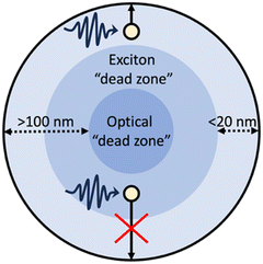 | ||
| Fig. 4 Schematic example of a particulate photocatalyst depicting: photoexcitation and exciton migration, the exciton “dead zone”, and the optical “dead zone”.10,60 | ||
2.2. Energy level alignment and heterojunctions
The alignment of the frontier energy levels for the appropriate redox reactions is important and was discussed briefly in the introduction (vide supra). It is important to reiterate that sufficient driving force is required to drive either the proton reduction or the water oxidation half reactions, however, materials with excessively wide optical gaps should be avoided as to maximise light harvesting. Recently, multicomponent organic photocatalyst systems have demonstrated increasingly higher efficiencies compared to analogous single-component systems (vide infra). For these multicomponent systems, appropriate frontier energy level alignments between both the redox potentials of the desired reactions and the semiconductors involved must be carefully considered. This is to allow for not only the desired redox reactions to proceed but also to allow charge (electron/hole) and energy transfer to occur between the semiconductors (Fig. 5).11,61,62 There are two types of energy level alignment which are of particular importance to these transfer mechanisms: type-I and type-II heterojunctions (Fig. 5). Type-I (straddling gaps) result in energy transfer from the donor to the acceptor, while type-II (staggered gaps) facilitates both charge and energy transfer pathways (Fig. 5).11,61,62 The processing of semiconductors into bulk heterostructures forms an abundance of interfaces in which energy/charge transfer processes can occur, which shortens the path length required of exciton to diffuse in order to reach an interface to allow for dissociation.25 However, there can be a trade-off of thermodynamic driving force for spatial separation afforded by the heterojunction, specifically there is a loss of driving force for reduction (electron transfer), oxidation (hole transfer), or both (energy transfer: type-I). For the most part, the heterostructures discussed herein fall into the type-II category and, consequently, charge transfer will typically be the principal transfer mechanism.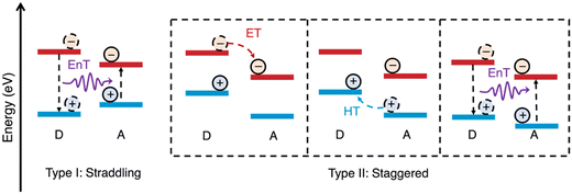 | ||
| Fig. 5 Schematic representations of energy level alignment of type-I and type-II semiconductor heterojunctions and energy transfer (EnT), electron transfer (ET), and hole transfer (HT) between donor (D) and acceptor (A) semiconductors. N.B. the arrow representing energy transfer does not represent a radiative process.11 | ||
2.3. Influence of co-catalyst loading
Metal co-catalysts, such as Pt and Pd, are often necessary to facilitate photocatalytic hydrogen evolution.63,64 Co-catalysts facilitate both charge separation and act as a proton reduction active site.63,64 Typically, Pt is deposited as the co-catalysts of choice due to it having the lowest overpotential for hydrogen evolution and a high work function.63 However, deposition of Pt can often be omitted as Pd (nano)particles remain with the material as residue from the polymer synthesis (i.e. Suzuki–Miyaura coupling).52,65,66 However, excessive loading of the metal co-catalyst on the polymer photocatalyst can become detrimental to their performance due to several compounding factors such as: shielding of light, surface active site coverage inhibiting interaction with sacrificial electron donors (SEDs)/water, and the co-catalyst acting as charge recombination centres.63 To avoid under or overloading the photocatalyst with Pt, various quantities of co-catalysts are, generally, screened to find an optimum loading. However, upon analysis, typically by inductively coupled plasma (ICP), the real loading of co-catalysts is generally found to be lower than what is expected. Furthermore, the actual loading of co-catalysts is often left unreported with only the theoretical value being provided. For these reasons only the optimised theoretical maximum co-catalyst loadings have been provided herein.3. Photoreactors
The major type of photoreactor utilised at the laboratory scale for organic semiconductor photocatalysts are closed system reactors, which are either batch-type or closed gas circulation systems. The batch-type system consist of a sealed vessel (such as cuvettes, round bottom flasks, or similar sealed reactors) which is optically transparent to the incident light and remains sealed during the course of photocatalysis. Both the liquid and headspace are purged with an inert gas (preferably argon) prior to photocatalysis.8 An airtight syringe or valved outlet is used to sample the headspace composition during photocatalysis. Whereas, a closed gas circulation systems consist of custom-made reaction vessels which are connected to an inert gas circulation system which is sampled at regular intervals by an inline gas chromatograph. In both cases the light source is provided externally, typically side on or top down. Batch-type reactors can suffer from pressure spikes during operation, which can cause a bias against the desired reaction. This arises from the reaction occurring within a sealed vessel. Conversely, continuous flow reactors can be used,67 such systems remove the gases continuously from the reactor into the inline detector system;68,69 therefore, these closed gas circulation systems operate at, comparatively, lower pressures and, consequently, provide a bias towards the forward reaction which will result in higher photocatalytic rates being observed compared to the batch-type reactor.84. Quantifying performance of photocatalysts
The sluggish rate of the 4-electron oxidation of water prevents many organic photocatalysts from performing OWS. Therefore, SEDs are employed which are more readily oxidised than water, substituting the water oxidation half-reaction.7 Common SEDs include: ascorbic acid (AA) and secondary/tertiary amines (diethylamine (DEA), triethylamine (TEA), and triethanolamine (TEOA)).70 However, other SEDs are also employed, such as methanol (MeOH), sodium sulfide, and dimethylphenylbenzimidazoline (BIH).70 The choice of SED will influence the HER significantly and should be considered carefully.The most commonly reported units for HER are:
(1) Absolute HER: quantity of hydrogen evolved per hour (mol h−1).
(2) Mass normalised HER: absolute rate normalised to the mass of the photocatalyst (mol h−1 g−1).
(3) Area normalised HER: absolute HER normalised to the photocatalyst area (mol h−1 m−2).
Mass normalised HERs are widely reported for organic photocatalysts, however, this metric is unreliable due to its strong dependence on photocatalyst concentration (Fig. 6(a)).71 Specifically, in dilute systems normalisation by photocatalyst mass can present falsely extravagant values (Fig. 6(b) and (c)).57,59,72 To circumvent this issue, Kisch et al. suggested bringing photocatalytic systems to optical saturation, at which point the absolute HER becomes independent of photocatalyst concentration.73,74 Alternatively, concentration dependent studies can be performed to evaluate mass normalised HERs over a range of photocatalyst concentrations.72,75 Regardless, HERs are generally unreliable and direct comparisons should be considered carefully due to the strong influence of reaction conditions, in particular differences in light sources, reactor shape, reactor volume, reactor pressure, but also the pH, temperature, and SED.57,59,70,71,76–80 A detailed discussion of reaction parameters for photocatalysts has been summarised elsewhere by Cao and Piao.80
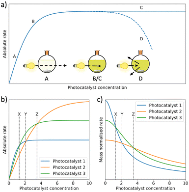 | ||
| Fig. 6 (a) Photocatalytic rate as a function of photocatalyst concentration. Between A and B, incident light can be transmitted through the reactor. Between B and C, the photocatalyst concentration has become high enough to extinguish all incident light. At point D, HER begins to decrease because of back-scattering. (b) The absolute HERs of 3 photocatalysts as a function of photocatalyst concentration and (c) mass normalised HERs of the same photocatalysts in (b) as a function of the photocatalyst concentration.53,71,80,81 | ||
External quantum efficiency (EQE), on the other hand, is a more comparable metric which compares the quantity of hydrogen evolved to the number of incident monochromatic photons.7,80
Mass normalised HER – while not the most reliable metric for photocatalysis (vide supra) – is typically reported as a value to indicate photocatalytic hydrogen evolution performance of materials and will be provided throughout, apart from film photocatalysts in which area normalised HER will be discussed.
5. Nanoparticles
The first class of processed materials discussed are PNPs, which also represent the smallest class of processed materials presented herein. PNPs have been extensively researched in recent years as photocatalysts for hydrogen evolution from water. They can be broadly defined by their sub-micrometre diameters (<1000 nm),82 yet, there is also a sub-class of PNPs referred to as conjugated polymer dots (Pdots) which possess even smaller diameters, typically less than 100 nm.75,83 However, the definition of Pdots is vague, as outlined by Tian and co-workers, in which they provide two different defining diameters for Pdots (<30 nm and <100 nm),75 while other sources specify diameters <20 nm.84,85 Therefore, for simplicity, the umbrella term of PNP will be used to describe Pdots and NPs collectively throughout.The small diameters of PNPs effectively puts all dimensions of the particle within the same order of magnitude as the exciton diffusion lengths of OSCs (5–20 nm), while both maximising the surface area to volume ratio and minimising the “dead volume”.55 However, PNPs notoriously suffer from poor stability due to the effects of Ostwald ripening and coalescence, resulting in increases in particles size which lowers photocatalytic performance.86,87 Nanoparticle stability can be improved through the use of long, polar side-chains which provide steric/electrostatic stabilisation.88 Alternatively, surfactants can be used, which adsorb to the NP surface forming stable micelles with the photocatalyst encapsulated within.82,86
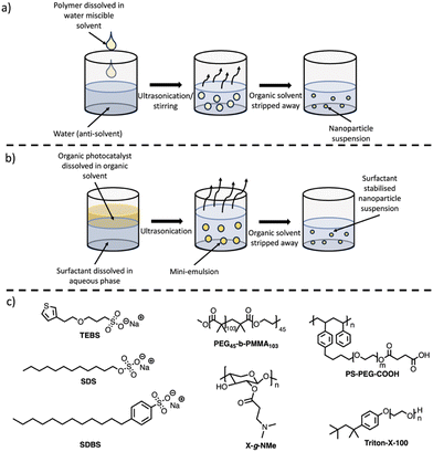
The two main methods to prepare PNPs are nanoprecipitation (Fig. 7(a)) and mini-emulsion (Fig. 7(b)).75,82 The method of processing (nanoprecipitation vs. mini-emulsion) can result in drastic morphological variations, as highlighted elsewhere.82,89 The following sub-sections will briefly outline these methods, however, more comprehensive discussion of PNPs for photocatalytic hydrogen evolution and their preparation can be found elsewhere.75 A summary of selected PNPs – including rates, diameters, and surfactants – has been tabulated and included in Table 2. Mass normalised HERs have been relayed throughout this review, as this is how they were reported in the original studies, however, it should be reiterated that direct comparison between mass normalised HERs are, at best, indicative of relative performance and values should be considered carefully (vide supra).
| Photocatalyst | Surfactant | HER /mmol h−1 g−1 | Co-catalyst | SED | Diameter (average)a/nm | Light source/nm | EQE/% | Ref. |
|---|---|---|---|---|---|---|---|---|
| a Determined using dynamic light scattering. b Determined using cyro-TEM imaging. c Determined using SEM imaging. | ||||||||
| Nanoprecipitation | ||||||||
| PFBT | PS-PEG-COOH | 8.3 | Residual Pd | AA | ∼30 | >420 nm, 17 W LED | 0.05 (550 nm) | 90 |
| 0.5 (445 nm) | ||||||||
| PFODTBT | PS-PEG-COOH | 50 | Residual Pd | AA | 30–40 | >420 nm, 17 W LED | 0.6 (550 nm) | 91 |
| PFTFQ-PtPy15 | PS-PEG-COOH | 21.7 | 15 mol% Pt | DEA | 34.28 | >420 nm, 20 W LED | 0.40 (515 nm) | 92 |
| PFTFQ-PtIq15 | PS-PEG-COOH | 11.1 | 15 mol% Pt | DEA | 35.41 | >420 nm, 20 W LED | 0.42 (515 nm) | 92 |
| PFODTBT (Hollow) | PS-PEG-COOH | 18.1 | Residual Pd | AA | 50 | >420 nm, 17 W LED | — | 93 |
| PBDTBT-7EO | — | 15.9 | 3 wt% Pt | AA | 5.9c | >300 nm, 300 W Xe | 0.30 (600 nm) | 94 |
| 0.13 (420 nm) | ||||||||
| HE-CP10-Dots | PEG45-b-PMMA103 | 0.84 | Residual Pd | AA | 69.5 | >420 nm, 300 W Xe | 0.9 (500 nm) | 95 |
| PF8TPA:PF8dfBT | X-g-NMe | 3.53 | 3 wt% Pt | AA | 299.6 | >420 nm, 300 W Xe | — | 96 |
| PFTBTA-PtPy | PS-PEG-COOH | 7.34 | TEA | 33.2 | >420 nm, 20 W LED | 0.27 (420 nm) | 97 | |
| PCDTBT:PC60BM | — | 105.2 | 9 wt% Pt | AA | — | >420 nm, 300 W Xe | 3.02 (595 nm) | 98 |
| 3.72 (420 nm) | ||||||||
| PFBT:PFODTBT:ITIC | PS-PEG-COOH | 60.8 | 6 wt% Pt | AA | ∼90 | >420 nm, 17 W LED | 4.1 (750 nm) | 61 |
| 7.1 (600 nm) | ||||||||
| 2.2 (450 nm) | ||||||||
| PC-PEG5 | — | 8.2 | Residual Pd | AA | ∼80 | Full arc, 300 W Xe | 5.3 (365 nm) | 88 |
| PS-PEG5 | — | 28.8 | 3 wt% Pt | AA | ∼130 | Full arc, 300 W Xe | 1.60 (420 nm) | 88 |
| 2.2 (405 nm) | ||||||||
| PTTPA:PFTBTA | — | 43.9 | 3 wt% Pt | AA | 35 | AM1.5G, 1000 W m−2, 380–780 nm, 350 W Xe | — | 99 |
| PBTTPA:PFTBTA | — | 41.0 | 3 wt% Pt | AA | 29 | AM1.5G, 1000 W m−2, 380–780 nm, 350 W Xe | — | 99 |
| PBDT-T | PS-PEG-COOH | 17.8 | 4 wt% Pt | AA | 15 | >420 nm, 20 W LED | 0.5 (460 nm) | 100 |
| PBDT-B3T | PS-PEG-COOH | 14.1 | 4 wt% Pt | AA | 19 | >420 nm, 20 W LED | 0.45 (460 nm) | 100 |
| PG6 | Triton-X-100 | 5.84 | 4 wt% Pt | AA | 124.1 | >420 nm, 20 W LED | 0.7 (460 nm) | 101 |
| PFODTBT:ITIC | PS-PEG-COOH | — | 6 wt% Pt | AA | ∼100 | >420 nm, 17 W LED | 2.1 (650 nm) | 102 |
| Y5 | PS-PEG-COOH | 22 | Pt, not specified | AA | 60 | AM1.5G, 1000 W m−2, 300 W Xe | 0.13 (850 nm) | 103 |
| 0.37 (750 nm) | ||||||||
| 1.0 (650 nm) | ||||||||
| PITIC-ThF Pdot | — | 339.7 | 3 wt% Pt | AA | 15.7 | >420 nm, 20 W LED | 4.76 (700 nm) | 47 |
| 3.9 (600 nm) | ||||||||
| Mini-emulsion | ||||||||
| PTB7-Th:EH-IDTBR | TEBS | 28.133 | 10 wt% Pt | AA | 81.9 | 350–800 nm, 300 W Xe | 6.4 (700 nm) | 104 |
| PTB7-Th:EH-IDTBR | SDS | 3.044 | 10 wt% Pt | AA | 45.2 | 350–800 nm, 300 W Xe | — | 104 |
| PM6:Y6 | TEBS | 43.7 | 10 wt% Pt | AA | 101.6 | AM1.5G solar simulator, 1000 W m−2 | 1.0 (900 nm) | 105 |
| 4.3 (400 nm) | ||||||||
| Y6 | SDS | 0.11 | 2 wt% Pt | AA | 48.5 | 400–900 nm, 1000 W m−1, 300 W Xe | — | 106 |
| Y6 | TEBS | 4.2 | 2 wt% Pt | AA | 78.3 | 400–900 nm, 1000 W m−1, 300 W Xe | 0.054 (780 nm) | 106 |
| PM6:TPP | TEBS | 72.75 | 20 wt% Pt | AA | 89.2b | 330–1100 nm, 1980 W m−2, 300 W Xe | 8.55 (800 nm) | 33 |
| 8.54 (700 nm) | ||||||||
| 7.93 (600 nm) | ||||||||
| 7.99 (500 nm) | ||||||||
| F8BT:photo-crosslinked | SDS | 11.024 | Residual Pd | AA | 21.99 | >420 nm, 300 W Xe | 0.8 (420 nm) | 107 |
| F1 | TEBS | 152.6 (15.67 μg mL−1) | 33 wt% | AA | 46.2 | AM1.5G solar simulator, 1000 W m−2 | 3.0 (800 nm) | 32 |
| 6.9 (600 nm) | ||||||||
| 3.8 (500 nm) | ||||||||
| PM6:PCBM | TEBS | 73.7 | 5 wt% Pt | AA | 86.71 | AM1.5G solar simulator, 1000 W m−2 | 2.6 (700 nm) | 105 |
| 8.7 (400 nm) | ||||||||
| gIDTBT:oIDTBR | SDS | 18.5 | 10 wt% Pt | AA | 68.96 | AM1.5G solar simulator, 1000 W m−2 | 2.8 (660 nm) | 108 |
| 1.0 (440 nm) | ||||||||
| Y6CO | TEBS | 230.98 (3.33 μg mL−1) | 37.5 wt% Pt | AA | 51.11 | AM1.5G, 1000 W m−2, 300 W Xe | 7.96 (800 nm) | 109 |
| 77.19 (26.67 μg mL−1) | 3.97 (700 nm | |||||||
| 3.88 (600 nm) | ||||||||
| 6.12 (500 nm) | ||||||||
| PM6:Y6CO | TEBS | 323.22 | 41 wt% Pt | AA | 51.93 | AM1.5G, 1000 W m−2, 300 W Xe | 10.73 (800 nm) | 109 |
| 11.58 (700 nm) | ||||||||
| 9.87 (600 nm) | ||||||||
| 9.92 (500 nm) | ||||||||
| PBDB-T:ITIC | SDBS | 257 | 10 wt% Pt | AA | ∼65 | 320–780 nm, AMG1.5, 300 W Xe | 9.9 (650 nm) | 110 |
| PM6:ITCC-M:IDMIC-4F | SDBS | 307 | 10 wt% Pt | AA | ∼85 | 320–780 nm, AMG1.5, 300 W Xe, 1000 W m−2 | 2.5 (700 nm) | 111 |
| 5.9 (600 nm) | ||||||||
| 2.9 (400 nm) | ||||||||
| PM6:IDMIC | SDBS | 328 | 15 wt% Pt | AA | ∼70 | 320–780 nm, AMG1.5, 300 W Xe, 1000 W m−2 | 3.6 (700 nm) | 112 |
| 5.4 (600 nm) | ||||||||
| 2.0 (400 nm) | ||||||||
| P10-e | SDS | 60.6 | Residual Pd | TEA/MeOH | 156 | >420 nm, 300 W Xe | 20.4 (420 nm) | 113 |
| Evaporation induced self-assembly | ||||||||
| CSCP:TDs | SDS | 1.37 | Residual Pd | TEOA | <100 nmc | >295 nm, 300 W Xe | 0.05 (420 nm) | 114 |
| 0.34 (395 nm) | ||||||||
| 1.08 (340 nm) | ||||||||
5.1. Nanoprecipitation for the preparation of PNPs
PNPs prepared via nanoprecipitation are formed by the rapid mixing of a dilute solution of conjugated polymer dissolved in a water-miscible organic solvent (such as THF) into an anti-solvent (water), with ultrasonication or vigorous stirring aiding the mixing process (Fig. 7(a)).86,87 The organic solvent is then removed by heating or with an inert gas purge. The major driving force for the formation of the PNPs is the hydrophobic effect, where the polymer chains fold into tight spheres as to minimise interactions with the aqueous phase.87 Although not required for the processing stage, surfactants (Fig. 7(c)) are often necessary to provide long-term stability and can enhance photocatalytic performance. The nanoparticle size is predominantly determined by the concentration of the polymer in the organic solvent, however, other parameters such as the solvent/anti-solvent ratio and stirring speed will also influence the size of the nanoparticles.1155.2. Synthesis of PNPs via mini-emulsion
The mini-emulsion method utilises organic solvents which are water immiscible. Firstly, the polymer is dissolved in a water immiscible organic solvent (e.g. chloroform, toluene, or xylenes), followed by high-shear mixing with an aqueous solution of a surfactant (Fig. 7(b)).86,87 This forms an oil-in-water mini-emulsion with the surfactant adsorbed to the nanoparticle surface which stabilises the nanoparticle by inhibiting Ostwald ripening and coalescence.87,116 The organic solvent is then removed by evaporation leaving stabilised PNPs in aqueous suspension. Unlike nanoprecipitation, surfactants are necessary to produce the mini-emulsion, however, this approach allows for a broader variety of organic solvents to be utilised due to the necessity of a water immiscible organic solvent. Control over particle size can be obtained through the shear force used to form the mini-emulsion, initial polymer concentration, surfactant concentration, and surfactant nature.1155.3. Photocatalytic activity of PNPs
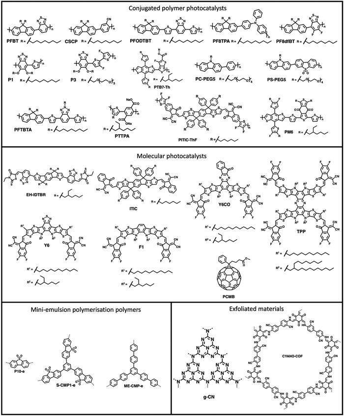
PNPs have were first explored for sacrificial hydrogen evolution by Tian and co-workers in 2016 in which PNPs were prepared by reprecipitation of the conjugated polymer PFBT (Fig. 8) with PS-PEG-COOH (Fig. 7(c)).90 These PFBT PNPs demonstrated a promising initial HER of 8.3 mmol h−1 g−1 (0.2 M AA, >420 nm, 17 W LED). However, they showed poor stability with photocatalytic performance decreasing rapidly within the first hour of irradiation.90 Following on from this, Tian and co-workers presented more examples of PNPs, in particular they presented PFODTBT (Fig. 8), a conjugated polymer with a similar backbone to PFBT with addition thiophene units which red-shifts the absorption of the polymer further into the visible region.91 PNPs of PFODTBT prepared under identical conditions to the previously reported PFBT demonstrated a HER of 50 mmol h−1 g−1 (0.2 M AA, >420 nm, 17 W LED), which was five times higher than PFBT PNPs, with stability exceeding 4 hours.91Since these early examples, a wide variety of PNPs systems have been explored, for example: compositional variation (surfactants and organic photocatalyst),101–117 cyclometallation to introduce catalytic sites,92–119 morphology variation (i.e., hollow nanoparticles),93 and architectural variation (hyperbranched versus linear polymers).95 Furthermore, the stability of nanoparticles has progressively improved, with many being stable for over 100 hours.101,118
5.4. Multi-component organic photocatalytic nanoparticles
Multi-component bulk heterojunction materials have received growing interest owing to their high photocatalytic efficiency compared to many single-component organic semiconductor photocatalysts. Heterojunctions improve photocatalyst efficiencies by aiding in exciton dissociation through the forming an abundance of interfaces within the bulk of the photocatalyst which allows for charge and energy transfer processes to occur (see Section 2.2.).11 Early examples of heterojunction PNPs were demonstrated by Zhang et al. in which they prepared a series of multi-component PNPs by nanoprecipitation using X-g-NMe (Fig. 7(c)) as a surfactant.96 Of these D/A PNPs they found that the most active blend, consisting of PF8TPA (Fig. 8) and PF8dfBT (Fig. 8), demonstrated a sacrificial hydrogen evolution rate 2.5 times greater than a physical mixture of the individual nanoparticles.96 They attributed this enhancement to photo-induced charge transfer between the donor (PF8TPA) and the acceptor (PF8dfBT).96 Furthermore, these PNPs also demonstrated good stability, with hydrogen being evolved over 20 hours of irradiation.96Yang et al. prepared organic/inorganic semiconductor nanocomposites consisting of the conjugated polymer CSCP (Fig. 8) and TiO2 quantum dots prepared via evaporation induced self-assembly.114,120 These nanocomposite PNPs demonstrated enhanced activity for photocatalytic hydrogen evolution compared to physical mixtures of the components without self-assembling into nanocomposites, with a maximum HER of 1.37 mmol h−1 g−1 (10 vol% TEOA, >295 nm, 300 W Xe light source).114 This enhancement was ascribed to energy transfer between CSCP and the TiO2 dots which was afforded by the formation of an intimate contact between the two components.114
Later, Kosco et al. prepared heterojunction PNPs via the mini-emulsion method consisting of the donor polymer PTB7-Th (Fig. 8) and the non-fullerene molecular acceptor EH-IDTBR (Fig. 8).104 After refinement of the composition and Pt co-catalyst loading, these heterojunction PNPs demonstrated an excellent HER of 28.1 mmol h−1 g−1 (10 wt% Pt, 0.2 M AA, 350 < λ < 800 nm, 300 W Xe light source) when TEBS (Fig. 7(c)) was used as the surfactant; significantly outperforming analogues prepared using SDS (Fig. 7(c)) which was 3.0 mmol h−1 g−1 (10 wt% Pt, 0.2 M AA, AM1.5G, 300 W Xe light source).104 This observation could be explained by differences in phase separation, whereby TEBS promoted the formation of intermixed heterojunction structures, whilst SDS resulted in phase separation. The EQE for the PNPs prepared using TEBS was estimated to be 6.2% at 700 nm in 0.2 M AA, which is one of the highest reported at this wavelength.104 Almost concurrently, Yang et al. reported a similar concept for hydrogen evolution in which polymer donor–molecular acceptor heterojunction PNPs were prepared via nanoprecipitation without the use of surfactants.106 An extensive library of 237 binary/ternary nanohybrids were prepared from 5 polymer donors and 4 molecular acceptors with varying donor/acceptor ratios being explored; they were then tested for sacrificial hydrogen evolution by high-throughput screening.98 The most active system from this library consisted of PCDTBT and PC60BM (Fig. 9) which possessed an excellent EQE of 3.02% of 595 nm using AA as the sacrificial agent and an average HER of 105.2 mmol h−1 g−1 (9 wt% Pt, 0.1 M AA, ≥420 nm, 300 W Xe light source). This was attributed to charge transfer between the donor polymer PCDTBT and molecular acceptor PC60BM: benefitting from the type-II offset between them.
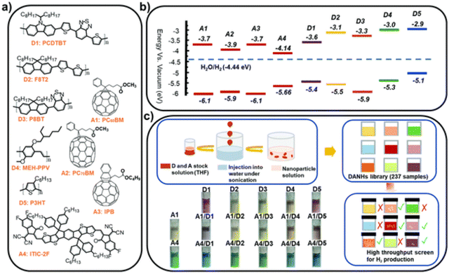 | ||
| Fig. 9 (a) Chemical structures and (b) energy levels of the conjugated polymer donors and molecular acceptors studied (c) nano-precipitation process used to prepare the DANHs and scheme representing high-throughput screening process for photocatalytic activity. Photographs show DANHs aqueous solutions in cuvettes. Reprinted under CC-BY 3.0 Licence.98 | ||
Separately, Liu et al. also explored ternary D1/D2/A PNPs consisting of the donor polymers PFBT and PFODTBT, and the non-fullerene molecular acceptor ITIC (Fig. 8) prepared via nanoprecipitation with PS-PEG-COOH.61 After refinement of the PNP composition, they reported an exceptional HER as 60.8 mmol h−1 g−1 (6 wt% Pt, 0.2 M AA, ≥420 nm, 17 W LED light source), with an excellent EQE of 7% at 600 nm.61 This impressive activity was attributed to the combination of both energy transfer (between PFBT and PFODTBT/ITIC) and charge transfer (between PFODTBT and ITIC), thus benefiting from both the type-I and type-II heterojunctions present (Fig. 10).61
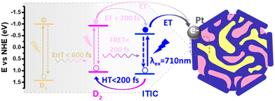 | ||
| Fig. 10 Scheme of photocatalytic pathways of ternary PNP reported by Liu et al. D1: PFBT; D2: PFODTBT. Reprinted under CC-BY 4.0 License.61 | ||
In 2022, Kosco et al. reported another D/A heterojunction PNP prepared from the donor polymer PM6 (Fig. 8) and the non-fullerene molecular acceptor Y6 (Fig. 8) which demonstrated sacrificial photocatalytic activity up to an astounding 900 nm, with an EQE of 1.0% at this wavelength.105 Lin and co-workers recently presented the non-fullerene molecular photocatalyst Y6CO (Fig. 8) based on Y6 which possessed a σ–π anchor designed to bind the Pt co-catalyst through π-back bonding.109 When prepared as a heterojunction PNP with PM6 they demonstrated an outstanding EQE at 800 nm of 10.73% and HER of 323.22 mmol h−1 g−1 (41 wt% Pt, 0.2 M AA, AM1.5G, 300 W Xe light source).109
Generally, these studies present similar findings; the formation of interfaces of semiconductors with appropriate energy level alignments – either type-I or type-II offset – improve photocatalytic performance due to charge/energy transfer providing greater charge carrier lifetimes. These are indeed both exciting and promising results, with clear progression being shown based on the efficiencies reported (see Table 1). A further detailed review of heterojunction photocatalysts can be found elsewhere.121
5.5. Photocatalytic PNPs prepared by flash nanoprecipitation
Flash nanoprecipitation (FNP) is a method of preparing nanoparticles under kinetic control.88 The rapid mixing of the polymer solution with the antisolvent prevents the formation of the larger, more thermodynamically stable nanoparticles which would be less desirable for photocatalysis.88,122 Yu et al. prepared PNPs by FNP and demonstrated them for sacrificial hydrogen evolution.88 They used a multi-inlet vortex mixer (MIVM, Fig. 11) to rapidly mix solutions of either the conjugated polymers PC-PEG5 or PS-PEG5 (Fig. 8) dissolved in THF with water within a millisecond timescale to form stable PNP suspensions. Stabilising surfactant were not necessary due to the long oligo(ethylene glycol) side-chains on PC-PEG5 and PS-PEG5 which provided electrostatic stabilisation. Importantly, Yu et al. demonstrated how varying the inlet flow rates into the MIVM allowed for significant procedural control over the particle sizes. Moreover, simple and reproducible scalability was demonstrated up to the litre scale. Upon comparison of PNPs prepared via FNP to those prepared by typical nanoprecipitation, they found PNPs prepared via FNP had improved light harvesting capabilities, smaller diameters, and narrower polydispersity. These enhancements were reflected in their HERs as PNPs of PC-PEG5 prepared by FNP demonstrated a sacrificial HER of 8.2 mmol h−1 g−1 (0.2 M AA, full arc, 300 W Xe light source), 23-times greater than PNPs prepared via bath ultrasonication (0.35 mmol h−1 g−1). PNPs of PS-PEG5 prepared by FNP demonstrated an excellent average HER of 28.8 mmol h−1 g−1 (3 wt% Pt, 0.2 M AA, full arc, 300 W Xe light source). However, relatively modest EQEs were reported, the highest of which was 2.92% at 405 nm for PS-PEG5 loaded with 3 wt% Pt and 5.3% at 365 nm for PC-PEG5 in 0.2 M AA. Interestingly, they found that PNPs prepared by FNP produce a stable, uniform colloid which did not require stirring to maintain the suspension, potentially opening opportunities for suspension based photoreactors which do not require agitation, greatly simplifying reactor design and potentially lowering operational costs.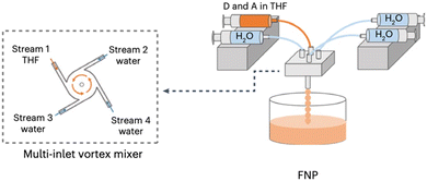 | ||
| Fig. 11 Schematic representation of the flash nanoprecipitation method utilised by Yu et al. to prepare PNPs and nanofibers. Adapted under CC-BY 4.0 License.123 | ||
5.6. Influence of surfactants on photocatalytic performance
As briefly discussed above, surfactants have a significant impact on the photocatalytic performance of PNPs and their involvement in PNPs has proven to be complex due to their influence on charge transfer behaviour, particle size, and particle morphology. Following is a review and discussion of studies which have looked into the involvement of surfactants on photocatalytic performance of PNPs.Kosco et al. demonstrated that the selection of the surfactant (TEBSvs.SDS) had a significant impact on the photocatalytic performance of their PTB7-Th:EH-IDTBR heterojunction nanoparticles (vide supra) which they attributed to morphological variations.104 Specifically, PNPs prepared using TEBS would produce intermixed PNPs, whereas PNPs prepared using SDS would phase separate and adopt a core–shell morphology. This core–shell morphology was expected to inhibit proton reduction as the electron acceptor, EH-IDTBR, was confined within the core; consequently, photoelectrons were unable to migrate to the surface to reduce protons.104 Furthermore, when they investigated the role of TEBS and SDS on PTB7-Th and EH-IDTBR individually they found that the choice of surfactant also influenced the crystallinity of the resultant nanoparticles. Nanoparticles of PTB7-Th were found to be amorphous with both SDS and TEBS. Whereas, EH-IDTBR formed a single crystal when prepared using SDS, yet adopted a polycrystalline morphology when TEBS was used.104 This is a non-trivial observation as crystallinity is important for charge transport in OSCs and will have significant implications on photocatalytic performance.124 The influence of the surfactant on internal morphology is not unique to this system and has been reported elsewhere for multi-component nanoparticle systems used for organic solar cells.125,126
The influence of TEBS and SDS on PNPs was further studied by Dolan et al. for single-component PNPs consisting of Y6.106 Similarly to Kosco et al., they found that PNPs prepared using TEBS possessed a higher photocatalytic rate (4.2 mmol h−1 g−1) than those prepared using SDS (0.11 mmol h−1 g−1) under broadband illumination (2 wt% Pt, 0.2 M AA, 300 W Xe light source).106 They suggested, however, that the surfactants adsorbed to the surface of the nanoparticles act as an insulating barrier and their findings suggested that PNPs prepared with SDS were expected to possess a denser surfactant layer at the surface than nanoparticles stabilised with TEBS. They go on to suggest that the surfactant layer of PNPs inhibits the deposition of Pt on the PNP which hinders photocatalytic performance.106 Therefore, they expect that the lower rate of PNPs prepared with SDS is due, at least in part, to this denser insulating layer at the nanoparticle surface. This observation was mirrored by Elsayed et al., in which they observed greater charge transfer resistance by electrochemical impedance spectroscopy for PNPs of PITIC-ThF prepared using surfactants (PS-PEG-COOH or Triton-X-100) than those prepared surfactant-free (Fig. 12), further providing evidence of the insulating role of surfactants.47 Similarly, Yang et al. briefly remarked a significant decrease in photocatalytic performance of multi-component PNPs when surfactants were introduced.98
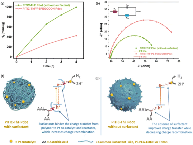 | ||
| Fig. 12 Diagram depicting a surfactant-stabilised PNP with a surfactant layer inhibiting the transfer of charge to SEDs/co-catalysts (left) and surfactant-free PNP (right). Reprinted under CC-BY 4.0 License.47 | ||
In 2021, Elsayed et al. demonstrated PNPs of the hydrophobic conjugated polymer PFTBTA (Fig. 8) with the hydrophilic conjugated polyelectrolyte PTTPA (Fig. 8).99 In this work they replaced the insulating surfactant PS-PEG-COOH with the conjugated polyelectrolyte PTTPA. Here, PTTPA provided both electrostatic stabilisation from its carboxylate side-chains and allowed for Förster resonance energy transfer (FRET) from PTTPA (donor) to PFTBTA (acceptor).99 These PFTBTA/PTTPA PNPs demonstrated a sacrificial HER of 43.9 mmol h−1 g−1 (2 wt% Pt, 0.1 M AA, AM1.5G, 350 W Xe light source), outperforming the single-component PNPs of PFTBTA (4.3 mmol h−1 g−1) and multicomponent PFTBTA/PTTPA PNPs prepared with PS-PEG-COOH (13.25 mmol h−1 g−1). This work demonstrates that surfactants could be replaced by hydrophilic photoactive materials, potentially opening up routes to further enhancing both the efficiency and stability of heterojunction PNPs.
An alternative approach of preparing PNPs which avoids the use of surfactants was recently reported by An et al. which they called the “MeOH/water cosolvent method”.127 For this cosolvent method, polymers are ultrasonicated in MeOH and added to water to form stable PNPs.127 However, unlike conventional nanoprecipitation, this cosolvent method does not remove the organic solvent from the mixture; instead the organic solvent is maintained throughout photocatalysis to aid in the stabilisation of the nanoparticles.127 Interestingly, they compared PNPs prepared by this cosolvent method with analogous PNPs prepared by conventional nanoprecipitation with PS-PEG-COOH and by mini-emulsion using SDS. They found that for their most active material, P3 (Fig. 8), the cosolvent approach greatly outperformed analogous PNPs prepared by the conventional routes (nanoprecipitation: 7600 μmol h−1 g−1; mini-emulsion: 8900 μmol h−1 g−1; cosolvent: 26![[thin space (1/6-em)]](https://www.rsc.org/images/entities/char_2009.gif) 000 μmol h−1 g−1) under identical photocatalytic conditions (0.2 M AA, ≥420 nm, 300 W Xe light source). These results further suggest that surfactants may inhibit photocatalytic performance. However, they also found that the highest HER for PNPs of their hydrophobic polymer, P1 (Fig. 8), was for PNPs prepared via mini-emulsion (330 μmol h−1 g−1), whereas PNPs of P1 prepared by the cosolvent method demonstrated no activity for hydrogen evolution. The lack of performance of the PNPs of P1 prepared by the cosolvent method was attributed to the poor of stability provided by the alkoxy side-chains. However, the amphiphilic surfactant used in the mini-emulsion method could also act to improve the interaction between water and the hydrophobic polymer.127 Like Yu et al., they found that oligo(ethylene glycol) side-chains, such as those on P3, provided effective electrostatic stabilisation of the nanoparticles with hydrogen being steadily evolved over a 15-hour period, compared to their alkyl alternatives, such as P1.88,127 These results highlight the subjectivity of photocatalyst preparation and their connection to structure–activity.
000 μmol h−1 g−1) under identical photocatalytic conditions (0.2 M AA, ≥420 nm, 300 W Xe light source). These results further suggest that surfactants may inhibit photocatalytic performance. However, they also found that the highest HER for PNPs of their hydrophobic polymer, P1 (Fig. 8), was for PNPs prepared via mini-emulsion (330 μmol h−1 g−1), whereas PNPs of P1 prepared by the cosolvent method demonstrated no activity for hydrogen evolution. The lack of performance of the PNPs of P1 prepared by the cosolvent method was attributed to the poor of stability provided by the alkoxy side-chains. However, the amphiphilic surfactant used in the mini-emulsion method could also act to improve the interaction between water and the hydrophobic polymer.127 Like Yu et al., they found that oligo(ethylene glycol) side-chains, such as those on P3, provided effective electrostatic stabilisation of the nanoparticles with hydrogen being steadily evolved over a 15-hour period, compared to their alkyl alternatives, such as P1.88,127 These results highlight the subjectivity of photocatalyst preparation and their connection to structure–activity.
Liu and co-workers demonstrated that surfactant concentration can also significantly impact the efficiency of photocatalytic hydrogen evolution.110 Higher starting concentrations of the surfactant SDBS (Fig. 7(c)) resulted in the formation of smaller PNPs but a denser surface layer of SDBS.110 This observation implies that there may be an optimum surfactant concentration which balances the competing influences of the density of the insulating surfactant layer and the diameter of the PNP.
These findings suggest that the impact of surfactants on photocatalytic performance is subjective with respect to the photocatalyst system being used, with the surfactant being beneficial in the case of many hydrophobic materials yet detrimental for more hydrophilic materials. Furthermore, it is clear that surfactant concentration is a key parameter that needs to be considered carefully during the preparation stage of these martials. While attempts have been made to fill this gap, further work is necessary to fully understand the role of surfactants.
5.7. Pre-polymerisation processing: mini-emulsion polymerisation
Aitchison et al. prepared a series of PNPs consisting of previously reported insoluble photocatalysts ME-CMP,128S-CMP1,129 and P10130via mini-emulsion polymerisation (Fig. 13).113 The CMP-type polymers prepared by mini-emulsion polymerisation ME-CMP-e and S-CMP1-e showed significant blue-shifting of their optical gaps (0.39 and 0.19 eV, respectively) compared to their analogues prepared via precipitation polymerisation. Whereas, the linear polymer prepared by mini-emulsion polymerisation, P10-e, possessed a smaller blue-shift (0.08 eV). These blue-shifts are likely due to the milder conditions necessary for the mini-emulsion polymerisation (90 °C vs. 150 °C used in bulk polymerisation) and was believed to lower the degree of polymerisation resulting in relatively stunted conjugation lengths. While under broadband irradiation (1![[thin space (1/6-em)]](https://www.rsc.org/images/entities/char_2009.gif) :
:![[thin space (1/6-em)]](https://www.rsc.org/images/entities/char_2009.gif) 1
1![[thin space (1/6-em)]](https://www.rsc.org/images/entities/char_2009.gif) :
:![[thin space (1/6-em)]](https://www.rsc.org/images/entities/char_2009.gif) 1 TEA/MeOH/water, ≥295 nm, 300 W Xe light source) all the nanoparticles (ME-CMP-e: 4.4 mmol h−1 g−1; S-CMP-e: 8.54 mmol h−1 g−1; P10-e: 29.46 mmol h−1 g−1) outperformed their bulk counterparts (ME-CMP: 1.72 mmol h−1 g−1; S-CMP: 5.92 mmol h−1 g−1; P10: 9.54 mmol h−1 g−1): benefitting from the larger surface area to volume ratio afforded by the mini-emulsion polymerisation. However, little enhancement or even reduced activity compared to their bulk analogues was observed for both ME-CMP-e (mini-emulsion: 46 μmol h−1 g−1; bulk: 52 μmol h−1 g−1) and S-CMP1-e (mini-emulsion: 2.59 mmol h−1 g−1; bulk: 1.84 mmol h−1 g−1) under visible light (1
1 TEA/MeOH/water, ≥295 nm, 300 W Xe light source) all the nanoparticles (ME-CMP-e: 4.4 mmol h−1 g−1; S-CMP-e: 8.54 mmol h−1 g−1; P10-e: 29.46 mmol h−1 g−1) outperformed their bulk counterparts (ME-CMP: 1.72 mmol h−1 g−1; S-CMP: 5.92 mmol h−1 g−1; P10: 9.54 mmol h−1 g−1): benefitting from the larger surface area to volume ratio afforded by the mini-emulsion polymerisation. However, little enhancement or even reduced activity compared to their bulk analogues was observed for both ME-CMP-e (mini-emulsion: 46 μmol h−1 g−1; bulk: 52 μmol h−1 g−1) and S-CMP1-e (mini-emulsion: 2.59 mmol h−1 g−1; bulk: 1.84 mmol h−1 g−1) under visible light (1![[thin space (1/6-em)]](https://www.rsc.org/images/entities/char_2009.gif) :
:![[thin space (1/6-em)]](https://www.rsc.org/images/entities/char_2009.gif) 1
1![[thin space (1/6-em)]](https://www.rsc.org/images/entities/char_2009.gif) :
:![[thin space (1/6-em)]](https://www.rsc.org/images/entities/char_2009.gif) 1 TEA/MeOH/water, ≥420 nm, 300 W Xe light source); likely the consequence of poorer light harvesting arising from their blue-shifted light absorption. P10-e, on the other hand, demonstrated a notably higher HER than its bulk counterpart under visible light irradiation, in which hydrogen was evolved at a rate of 14.52 vs. 6.13 mmol h−1 g−1, respectively. When the concentration of P10-e was reduced to that typically used for Pdots (from 0.1 mg mL−1 to 13 μg mL−1), the mass normalised HER increased by over 3-fold to 60.6 mmol h−1 g−1. This sharp increase in rate is unsurprising given the concentration dependence of photocatalytic rate (vide supra). Upon optimising the photocatalytic conditions, an outstanding EQE of 20.4% was achieved at 420 nm.
1 TEA/MeOH/water, ≥420 nm, 300 W Xe light source); likely the consequence of poorer light harvesting arising from their blue-shifted light absorption. P10-e, on the other hand, demonstrated a notably higher HER than its bulk counterpart under visible light irradiation, in which hydrogen was evolved at a rate of 14.52 vs. 6.13 mmol h−1 g−1, respectively. When the concentration of P10-e was reduced to that typically used for Pdots (from 0.1 mg mL−1 to 13 μg mL−1), the mass normalised HER increased by over 3-fold to 60.6 mmol h−1 g−1. This sharp increase in rate is unsurprising given the concentration dependence of photocatalytic rate (vide supra). Upon optimising the photocatalytic conditions, an outstanding EQE of 20.4% was achieved at 420 nm.
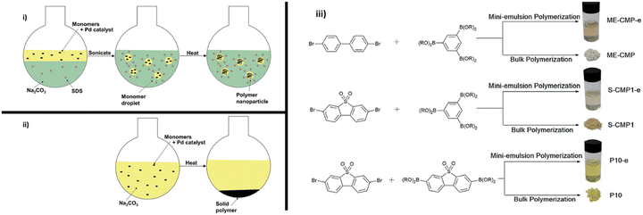 | ||
| Fig. 13 Mini-emulsion polymerisation utilised by Aitchison et al. Reproduced under CC-BY 3.0 License.113 | ||
5.8. Exfoliation: polymer photocatalyst nanosheets
The previous sections have discussed the processing of conjugated organic materials into PNPs by solution processable techniques, in which the components are soluble, or at least initially in the case of mini-emulsion polymerisation. However, insoluble 2D layered polymeric structures, such as CNs,131 CTFs,132 and COFs,133 can be partially deconstructed by breaking the relatively weak van der Waals forces between layers through physical or chemical exfoliation to form highly active materials (Fig. 14).131 By separating these layers into nanosheets the properties of these materials can be augmented, granting the materials with more active sites by virtue of increased surface area and shorter paths for exciton diffusion compared to their bulk materials.53 However, they often also possess larger optical gaps and reduced crystallinity which may prove to be detrimental.50 As a method of improving photocatalytic performance, exfoliation has been employed as early as 2013 by Yang et al. to physically exfoliate g-CN (Fig. 8) to form nanosheets with ∼2 nm in thickness.134 Compared to the bulk material, the g-CN nanosheets demonstrated over an 8-fold enhancement in sacrificial HER (93 μmol h−1vs. 10 μmol h−1) under the same photocatalytic conditions (10 vol% TEOA, ≥420 nm, 300 W Xe light source).134 Since then, significant work has been presented on the exfoliation of CNs,135–140 COFs,141–145 CTFs,50 and conjugated porous polymers146 into nanosheets, demonstrating the versatility of the process. Some recent examples have shown even greater enhancements with an outstanding EQE reported of 82.6% at 450 nm for CYANO-CON (Fig. 8) and a mass normalised HER of 134.2 mmol h−1 g−1 (1 wt% Pt, 0.1 M AA, ≥420 nm, 300 W Xe light source), more than double the rate of the bulk counterpart, CYANO-COF.1476. Nanofibers
Nanofibers are materials processed so that they have two spatial dimensions on the nanometre scale (10s–100s nm), while the remaining dimension can extend into the micrometre scale.148 They have been prepared in a number of ways for photocatalytic hydrogen evolution including electrospinning, crystallisation-driven self-assembly, and pre-polymerisation templating methods. Like PNPs, they are applied in suspension-based systems and, therefore, possess similar advantages and drawbacks. However, due to their fibrous nature they are less susceptible to the effects of aggregation whilst also maintaining high specific surface areas, and, therefore, are expected to have greater photocatalytic stability than PNPs.1496.1. Electrospinning of polymer photocatalysts
Electrospinning is a facile, low-cost, and simple method for processing soluble organic semiconductors into non-woven nanofiber meshes possessing submicron diameters and large surface area to volume ratios.150–152 Control of the nanofiber morphology, such as diameter, and composition can be facially obtained through simple procedural changes such as: flow rate, polymer concentration, bias, emitter aperture diameter, and solvent volatility.151 Lin and co-workers prepared non-woven nanofiber mesh heterojunction photocatalysts consisting of PTB7-Th and IDTBR (Fig. 15).48 Poly(ethylene oxide) (PEO) or poly(vinylpyrrolidone) (PVP) (Fig. 15) were incorporated as supporting matrices to improve water wettability.48 Both nanofiber composition and diameters in the range of 800–2100 nm were explored due to the control afforded by electrospinning. Unsurprisingly, the narrowest nanofibers (800 nm) demonstrated the greatest activity for sacrificial HER of 24.38 mmol h−1 g−1 (3 wt% Pt, 0.2 M AA, λ ≥ 300 nm, 300 W Xe), consisting of a 3![[thin space (1/6-em)]](https://www.rsc.org/images/entities/char_2009.gif) :
:![[thin space (1/6-em)]](https://www.rsc.org/images/entities/char_2009.gif) 7 ratio of PTB7-Th
7 ratio of PTB7-Th![[thin space (1/6-em)]](https://www.rsc.org/images/entities/char_2009.gif) :
:![[thin space (1/6-em)]](https://www.rsc.org/images/entities/char_2009.gif) IDTBR using PEO as the matrix polymer.48 This was a 34-fold enhancement of rate compared to analogous single-component nanofibers prepared from PTB7-Th. As expected, the study found that HER increased with decreasing nanofiber diameter which is likely due to narrower nanofibers having a greater density of surface active sites, minimised “dead volume”, and shorter path lengths for excitons to reach the surface. Interestingly, they also reported that the choice of the matrix polymer can have a significant impact on the HER, as PEO was 2.81 times more active for sacrificial hydrogen evolution than PVP. Unlike the behaviour of the surfactants discussed above, the authors instead suggest that the PEO matrix, being water soluble, was leached into the aqueous SED medium, resulting in more porous, narrower nanofibers.48 While these nanofibers possess relatively large diameters (>800 nm), compared to other organic photocatalyst nanofibers (vide infra), they still provide a demonstration of a facile method to produce nanofiber photocatalysts with excellent procedural control.151
IDTBR using PEO as the matrix polymer.48 This was a 34-fold enhancement of rate compared to analogous single-component nanofibers prepared from PTB7-Th. As expected, the study found that HER increased with decreasing nanofiber diameter which is likely due to narrower nanofibers having a greater density of surface active sites, minimised “dead volume”, and shorter path lengths for excitons to reach the surface. Interestingly, they also reported that the choice of the matrix polymer can have a significant impact on the HER, as PEO was 2.81 times more active for sacrificial hydrogen evolution than PVP. Unlike the behaviour of the surfactants discussed above, the authors instead suggest that the PEO matrix, being water soluble, was leached into the aqueous SED medium, resulting in more porous, narrower nanofibers.48 While these nanofibers possess relatively large diameters (>800 nm), compared to other organic photocatalyst nanofibers (vide infra), they still provide a demonstration of a facile method to produce nanofiber photocatalysts with excellent procedural control.151
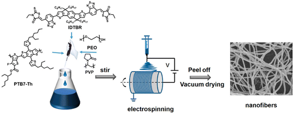 | ||
| Fig. 15 The electrospinning process used to prepare D–A nanofibers. Reprinted under CC-BY 4.0 License.48 | ||
6.2. Crystallisation-driven self-assembly of photocatalysts
Based on their earlier success using the living crystallisation-driven self-assembly (CDSA) method to produce photocatalytic nanofibers for hydrogen evolution using photosensitised aliphatic polymers,153 Manners and co-workers further demonstrated how conjugated polymers could be utilised in the development of nanofibers with crystalline cores, potentially possessing extremely high exciton diffusion lengths (>200 nm).154–156 A representative example of the structure of the most active of the nanofibers prepared by the CSDA-seeded growth method is outlined in Fig. 16. Controlled growth of the nanofibers was obtained through the addition of feed solutions to the seed solution, providing control over the composition and length of the nanofibers, with lengths of ca. 260–850 nm being explored. Photosensitisation was provided by the crystalline polyfluorene-based core, while the corona consisting of poly(ethylene glycol) and quaternary ammonium groups provided colloidal stability. The Co(II) porphyrin molecular catalysts are selectively bound to the nanofibers ends by electrostatic interactions with the quaternary ammonium groups at the termina of the nanofibers (Fig. 16). It is believed that the significant overlap between the triblock nanofiber's emission spectra and the Co(II) porphyrin absorption spectrum allowed for efficient FRET.157 Through this FRET mechanism, energy could be funnelled from the core of the nanofiber to the Co(II) photocatalyst electrostatically bonded to the nanofiber's corona. After optimising the length and composition of the nanofibers, the highest HER obtained was 65 mmol h−1 g−1 (6 wt% Co, 10 mM TEOA, λ < 405 nm, 500 W Xe light source) for a nanofibers of lengths ca. 440 nm (100–240–100 nm triblock) irradiated using exclusively UV light.154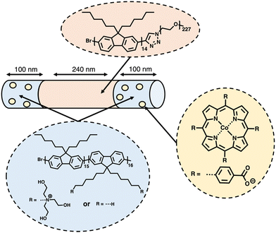 | ||
| Fig. 16 Schematic representation of the nanofibers prepared via CDSA by Manners and co-workers discussed herein.154 | ||
6.3. Photocatalytically-active molecular nanofibers
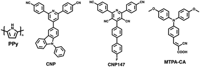
Yang et al. prepared nanoaggregates of the molecular photocatalyst CNP (Fig. 17), which adopted either an amorphous nanosphere morphology (CNP-s) or a crystalline nanofiber morphology (CNP-f).31 These nanoaggregates were prepared via nanoprecipitation from THF into water in which morphological control was obtained by the THF/water ratio. However, it was also found that CNP-s were thermodynamically unstable and would spontaneously adopt the CNP-f morphology over time.31 The crystalline CNP-f demonstrated significantly greater photocatalytic performance for hydrogen evolution compared to the amorphous CNP-s, in which CNP-f continuously evolved hydrogen with a HER of 11.7 mmol g−1 h−1 (3 wt% Pt, 0.1 M AA, λ > 420 nm, 300 W Xe light source) over 34 hours, 72 times greater than CNP-s (0.44 mmol h−1 g−1).31 The increased photocatalytic activity of CNP-f for hydrogen production was attributed to several factors. Firstly, their results suggest that the efficiency of electron transfer from the photocatalyst to the Pt co-catalyst is more efficient in CNP-f than in CNP-s. Secondly, the π–π stacking in CNP-f allows for improved intermolecular charge transfer and provides longer charge transfer distances. Finally, the relatively high photoluminescence quantum yield of CNP-s resulted in significant radiative losses, further contributing to the reduced photocatalytic efficiency. Interestingly however, they also observed a switch in photocatalytic selectivity when utilised for H2O2 evolution, in which CNP-s demonstrated greater photocatalytic performance than CNP-f. This observation was explained by the wider band gap of CNP-s providing greater thermodynamic driving forces for water oxidation and oxygen reduction, as well as CNP-f demonstrating greater selectivity for the completive side-reaction of singlet oxygen production.Zhang et al. recently demonstrated a heterojunction nanofiber comprised of the molecular acceptor CNP147 (Fig. 17) and molecular MTPA-CA (Fig. 17) which was identified through a high-throughput screen of 6 molecular donors and 26 molecular acceptors.123 The MTPA-CA:CNP147 nanofibers were prepared by FNP (vide supra) and possessed diameters of ca. 30 nm and lengths of several μm. After optimisation of composition and co-catalyst loading these nanofibers demonstrated an impressive sacrificial HER of 330 mmol h−1 g−1 (9 wt% Pt, 0.2 M AA, full arc, 300 W Xe light source) and an outstanding EQE of 80.3% at 350 nm, which are among the highest reported values for organic photocatalysts. The authors suggested that this efficiency was due to the type-II band gap offset between MTPA-CA (donor) and CNP147 (acceptor) which facilitated effective charge separation and inhibited electron–hole recombination.
6.4. Pre-polymerisation processing: templating of nanofiber photocatalysts
In 2017, Yao and co-workers prepared Ag-g-C3N4 porous nanofibers prepared via a supramolecular hydrogel-based templating method.159 The hydrogel template was prepared by heating melamine and AgNO3 in water to 90 °C and then cooling to room temperature.159 The hydrogel was then freeze-dried, and heated to 550 °C to polymerise, forming the nanofibers.159 The most active of theses nanofibers, Ag-g-C3N4-2, evolved hydrogen at a rate of 625 μmol h−1 g−1 (1 wt% Pt, 10 vol% TEOA, λ > 420 nm, 300 W Xe) which was 6.6 times greater than that of bulk g-C3N4 under identical conditions.159Ghosh et al. prepared poly(pyrrole) (PPy, Fig. 17) nanofibers functionalised with noble-metal nanoparticles which facilitated localised surface plasmon resonance (LSPR) which allowed for photocatalysis in to the near infra-red (NIR).158 These PPy nanofibers were prepared using a soft-templating method followed by the chemical oxidative polymerisation of pyrrole.158,160,161 Noble-metal nanoparticles were then deposited on the PPy nanofibers from their respective salts using steady-state γ irradiation from a 60Co source, yielding nanofibers decorated with the nanoalloys. The resultant nanofibers possessed diameters of 50 nm and lengths greater than 2 μm, while the noble-metal nanoparticles decorating the surface possessed diameters of 10–24 nm.158 The PPy nanofibers functionalised with Au nanoparticles demonstrated a promising HER of 15 mmol h−1 g−1 (25 vol% MeOH, λ ≥ 420 nm, 250 W Xe light source), while the Au50Pt24Pd26 nanoalloy factionalised nanofibers exhibited a higher HER of 40 mmol h−1 g−1 under identical conditions. However, PPy nanofibers without noble-metal nanoparticles possessed a modest HER of 7 mmol h−1 g−1. The authors provided several reasons for the role of noble-metal nanoparticles in enhancing the photocatalytic performance. Firstly, the noble-metal nanoparticles absorbed photons which resulted in LSPR which could, subsequently, undergo non-radiative decay to produce hot electrons.162 These hot electrons could then be injected into the nanofibers to subsequently reduce protons.158 Secondly, they suggested a Schottky barrier forms between the metal nanoparticles/polymer interface which facilitated unidirectional transfer of electrons from the metal nanoparticle to the nanofibers; inhibiting electron–hole recombination.158 Thirdly, the enhanced HER of the nanoalloy over pure Au nanoparticles was believed to be due to suppressed electron–hole recombination of hot electrons in nanoalloys and the role of Pd/Pt in proton reduction.158
7. Photocatalytically-active films
PNPs, nanosheets, and nanofibers are frequently utilised in suspension-type reactors which have considerable limitations, as outlined by Hisatomi and Domen.163 Following is a brief summary of these limitations. Firstly, large scale suspension-based reactors are expected to have unavoidable and unreasonable cost and bulk associated with their operation.163 Secondly, photocatalyst sedimentation will result in inefficiencies due to shadowing effects, unless under continuous agitation, adding further to the complexity and cost of the photoreactor.163 Finally, the recovery of the photocatalyst is a time consuming and, potentially, lossy process, contributing further to the maintenance cost of suspension based reactors.163 The question of feasibility of suspension-based systems becomes stressed when these issues are compounded. However, film-based photocatalytic reactors possess none of these limitations. For example, film-based photoreactors are expected to be less bulky as they require less water compared to suspension-based reactors due to being flat. Furthermore, due to their modular nature, films can be easily recycled and cannot suffer from sedimentation or aggregation effects. Finally, scattering effects are lower in film-type devices compared to suspension-based systems (Fig. 18) and therefore optical losses are expected to be lower due to reduced back-scattering.164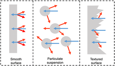 | ||
| Fig. 18 Light distribution in flat and nanostructured films, and in particle suspensions. Blue arrows signify incident light and red arrows signify scattered/reflected light. N.B. the size of the arrows do not signify intensity of light scattering.164 | ||
Importantly, they also demonstrate the capacity for simple scalability through roll-to-roll printing using well established methods such as: blade coating, slot die coating, Gravure printing, inkjet printing, and screen printing (Fig. 19).165–167 Furthermore, the surface texturing of films has the potential to improve light harvesting whilst also maximising the number of surface active sites (Fig. 18).164
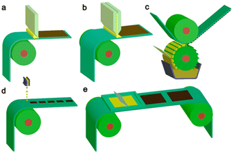 | ||
| Fig. 19 Common scalable solution processing methods for large-area flexible OSCs which are compatible with roll-to-roll processing. (a) Blade coating, (b) slot die coating, (c) Gravure printing, (d) inkjet printing, (e) screen printing. Reproduced under CC-BY 4.0 License.165 | ||
Films can be categorised based on their thickness: thick-film (>200 nm) and thin-film (<200 nm), herein these have been compiled together as simply films or film-type devices due to the thickness either not having been reported or being greater than 200 nm, and, therefore, cannot be defined as thin-film.168 A collection of organic photocatalyst films for hydrogen evolution, including experimental details and substrates, have been tabulated in the Table 3.
| Photocatalyst | HER /mmol h−1 m−2 | Co-catalyst | SED | Thickness/nm | Substrate material | Light source/nm | EQE /% | Ref. |
|---|---|---|---|---|---|---|---|---|
| a mmol h−1 g−1, area normalised rate not reported. b Determined from the suspension, not from thin-film. c Determined using natural seawater. | ||||||||
| Soluble materials | ||||||||
| P8-s | 0.45a | Residual Pd | TEA | — | Mesoporous SnO2 | >295 nm 300 W Xe | 0.56b (420 nm) | 169 |
| FS-TEG | 6.4 | Residual Pd | TEA | 113 | Glass – OTS functionalised | >420 nm 300 W Xe | 10b (420 nm) | 43 |
| FS-5Dodec | 0.136 | Residual Pd | TEA | 4000–6000 | Glass – Frosted | >420 nm, 300 W Xe | — | 49 |
| FS-5Dodec-20 min | 1.131 | Residual Pd | TEA | 4000–6000 | Glass – Frosted | >420 nm, 300 W Xe | — | 49 |
| PSO-FNBr | 12.2 | 3 wt% Pt | TEOA | <1000 | Glass | >420 nm, Xe (unspecified power) | 1.45 (420 nm) | 170 |
| FS-5 | 9.525 | Residual Pd | TEA/MeOH | 4000–6000 | Glass | >420 nm 300 Xe | 2.07 (420 nm) | 76 |
| PTA | 8.0 | 4.6 wt% Pt | AA | — | Non-woven fabric | AM1.5G, 300 W Xe | 13.5 (420 nm)b | 171 |
| P-HEG-10 | 16.6 | Residual Pd | TEA/MeOH | 580 | Si wafer | 380–780 nm, 350 W Xe | 17.82 (460 nm)b | 172 |
| PBDB-T | 107.5 | Residual Pd | TEA/MeOH | 1800 | Glass | >420 nm, 500 W Xe | — | 173 |
| PBDTTTSOS | 150.7 | 3 wt% Pt | TEA/MeOH | — | Glass – UV/O3 treated | >420 nm, 350 W Xe | 14.9b | 174 |
| 18.9bc (500 nm) | ||||||||
| PS-OTEG | 6.0 | Residual Pd | TEA | — | Glass – Frosted, OTS functionalised | >420 nm, 300 W Xe | 5.3 (420)b | 175 |
| PS-OTEG | 0.67 | Residual Pd | AA | — | Glass – Frosted, OTS functionalised | >420 nm, 300 W Xe | — | 175 |
| Insoluble materials | ||||||||
| FS-COF | 24.9 | 8 wt% Pt | AA | — | Glass | >420 nm, 300 W Xe | 3.2b (420 nm) | 176 |
| PtSA-MNS | 17.8 | 12 wt% Pt | AA | 3800 | Glass | >420 nm, | — | 177 |
| 300 W Xe | ||||||||
| PDBTSO | 28.97 | 3 wt% Pt | TEOA/K2HPO4 | — | Glass | >420 nm, 300 W Xe | — | 178 |
| r-CTF NSs | 25.7 | 3 wt% Pt | TEOA | ∼60 | Glass | >420 nm, 300 W Xe | 1.8 (500 nm) | 140 |
| 3.1 (420 nm) | ||||||||
| BSO2-EDOT | 132.2 | Residual Pd | AA | — | Glass | >420 nm, 300 W Xe | 13.6b (550 nm) | 35 |
| 2D-TPs | 135.2 | 3 wt% Pt | TEOA | — | Nylon membrane | >420 nm, 300 W Xe | 29.5b (420 nm) | 50 |
| 0.5b (700 nm) | ||||||||
| ZVCOF-1 | 402.1 | 1 wt% Pt | AA | — | Nylon membrane | >420 nm, 300 W Xe | 1.6 (650 nm) | 179 |
| 47.1 (420 nm) | ||||||||
| CTF-HUST-film | 5.4 | 2 wt% Pt | TEOA | ∼500 | Glass | >420 nm, 300 W Xe | 0.11 (420 nm) | 180 |
| CTF-TPA-Film-5 | 213.3 | 6 wt% Pt | TEOA | 2700 | Glass – film grown on substrate | >420 nm, 300 W Xe | 8.6 (475 nm) | 181 |
| HOF-H4TBAPy | 114 | — | AA | — | Non-woven cellulose fabric | Full arc, 1000 W m−2, 300 W Xe | — | 182 |
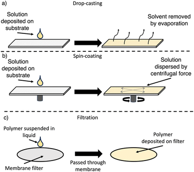
Photocatalytic film-type devices for hydrogen evolution have been prepared in several ways ranging from the simplistic route of capturing suspended particulate photocatalysts on membrane filters to sophisticated bottom-up approaches in which the polymer is grown upon to the substrate's surface. However, the most frequently used and earliest adopted approach is drop-casting, likely stemming from its convenience due to minimal equipment requirements and it having no requirements for material solubility.169 The route in which materials are deposited to form the film can, unsurprisingly, influence the mechanical and optoelectronic properties of the resulting material, which could have a significant impact on the photocatalytic performance.183,184 Following is a brief outline of the three most commonly utilised approaches for processing organic semiconductors into film-type devices for photocatalytic hydrogen evolution.
7.1. Drop-casting
For drop-casting, the polymer is dissolved (or suspended) in a volatile solvent, deposited on the substrate, and following evaporation of the solvent a film forms upon the substrate surface (Fig. 21(a)). The slow evaporation allows for some self-assembly into more ordered films to occur, however, this approach typically produces grainier films.166 Control over the film thickness can be obtained by the total quantity of material deposited on the substrate surface. Drop-casting has been utilised in the preparation of films from both soluble and insoluble OSCs.7.2. Spin-coating
For spin-coating, the polymer is dissolved in a suitable solvent, deposited on the substrate, which is then rotated at high speed, spreading the solution evenly across the surface by centrifugal forces (Fig. 21(b)). Spin-coating allows for greater control over the film morphology, particularly the film thickness and homogeneity.166,185 However, spin-coating is not a continuous process, is not scalable, requires specific equipment, and results in significant loss of material.166,185 Furthermore, compared to drop-casting, molecular ordering is low due to the rapid evaporation of solvent.1867.3. Filtration
This relatively simple approach of preparing film-type devices consists of simply filtering an organic semiconductor suspension through a membrane assisted by a vacuum (Fig. 21(c)).187 Filtration is a commonly utilised approach for the deposition of organic materials to produce membrane devices.187 During filtration, the disordered nanomaterials in suspension can self-assemble into ordered membranes, with control over the thickness being determined by the total quantity of material being filtered.187 Importantly, this method does not require the OSC to be in solution and, therefore, has been primarily used for insoluble photocatalysts.7.4. Photocatalytically-active films of soluble materials
In 2017, Woods et al. processed the chloroform soluble linear polymer P8-s (Fig. 20) into a film photocatalyst for sacrificial hydrogen evolution by drop-casting from chloroform onto mesoporous SnO2.169 As with many early photocatalysts, the HER of the P8-s film was rather modest at 450 μmol g−1 h−1 (5 vol% TEA, >295 nm, 300 W Xe light source).169 More recently, however, an outstanding area normalised HER was reported by Lin et al. for a solution processable polymer in which the drop-casted acceptor–acceptor polymer PBDTTTSOS (Fig. 20) demonstrated a HER of 150.7 mmol h−1 m−2 (3 wt% Pt, 1![[thin space (1/6-em)]](https://www.rsc.org/images/entities/char_2009.gif) :
:![[thin space (1/6-em)]](https://www.rsc.org/images/entities/char_2009.gif) 1
1![[thin space (1/6-em)]](https://www.rsc.org/images/entities/char_2009.gif) :
:![[thin space (1/6-em)]](https://www.rsc.org/images/entities/char_2009.gif) 1 TEA/MeOH/water, >420 nm, 350 W Xe light source). However, these examples demonstrate little beyond application of soluble materials utilised as films. Following is a discussion of some studies performed looking more in depth at how films have been adapted to improve photocatalytic performance.
1 TEA/MeOH/water, >420 nm, 350 W Xe light source). However, these examples demonstrate little beyond application of soluble materials utilised as films. Following is a discussion of some studies performed looking more in depth at how films have been adapted to improve photocatalytic performance.
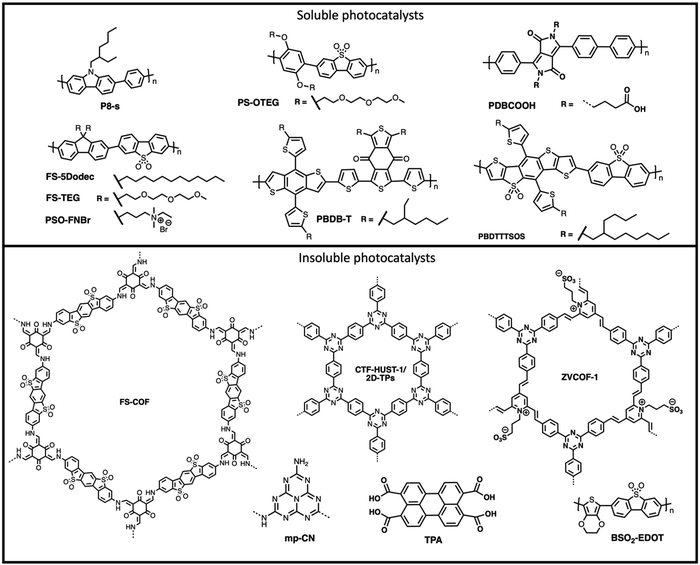 | ||
| Fig. 20 Chemical structures of materials discussed for application as film-type photocatalytic devices in the main text. | ||
7.5. Influence of film thickness on photocatalytic-activity
Building upon their earlier example, Woods et al. demonstrated spin-coated films of the co-polymer of dibenzo[b,d]thiophene sulfone and fluorene functionalised with hydrophilic oligo(ethylene glycol) side-chains (FS-TEG, Fig. 20) on glass substrates for photocatalytic hydrogen evolution.43 Utilising the control provided by spin-coating, they explored the influence of film thickness on photocatalytic performance; the thickest of these films (113 nm) demonstrated the greatest activity for sacrificial hydrogen evolution, generating hydrogen at a rate of 6.4 mmol h−1 m−2 (5 vol% TEA, >420 nm, 300 W Xe light source).43 Experiments in which they stacked films demonstrated how they could further enhance the photocatalytic activity of these film-type photoreactors, with the HER increasing from 4.8 mmol h−1 m−2 for a single slide to 9.6 mmol h−1 m−2 for three stacked slides (Fig. 22).43 This was possible as the films did not completely extinguish useful light incident on the films.43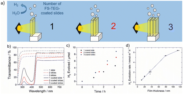 | ||
| Fig. 22 (a) Schematic diagram of FS-TEG coated glass slides stacked in series; (b) UV-vis transmittance spectra of slides stacked in series; (c) hydrogen evolved of stacked slides under visible light; (d) hydrogen evolution rates of FS-TEG films at varying thicknesses. Reprinted under CC-BY 3.0 License.43 | ||
The relationship between film thickness and photocatalytic performance was also explored by Cao et al. using films of PBDB-T (Fig. 20).173 Contrary to the observations of Woods et al., Cao et al. observed that increasing film thickness resulted in lower HERs. The thinnest (1.8 μm) and most active of these PBDB-T films had an impressive HER of 107.5 mmol h−1 m−2 (1![[thin space (1/6-em)]](https://www.rsc.org/images/entities/char_2009.gif) :
:![[thin space (1/6-em)]](https://www.rsc.org/images/entities/char_2009.gif) 1
1![[thin space (1/6-em)]](https://www.rsc.org/images/entities/char_2009.gif) :
:![[thin space (1/6-em)]](https://www.rsc.org/images/entities/char_2009.gif) 1 TEA/MeOH/water, >420 nm, 500 W Xe light source), whereas the thickest film (8.4 μm) possessed the lowest HER of 39.9 mmol h−1 m−2.173 The difference in relationship between film thickness and HER between FS-TEG and PBDB-T becomes trivial when considering the thicknesses studied. For FS-TEG, the thicknesses studied were relatively small (11.3–113 nm),43 which are of the order of the typical exciton diffusion lengths of OSCs (<20 nm).55 Whereas, for the PBDB-T films, the thicknesses were notably larger (1800–8400 nm), two orders of magnitude greater than the typical exciton diffusion lengths of OSCs, which undoubtably will contributed to lower efficiencies. However, it should be noted that there was a strong indication of swelling of the FS-TEG films in the photocatalytic mixture which increased the permeability of water into the polymer film.43 This increase of accessibility of water/SEDs to active sites within the polymer film would indeed be a contributing factor to the increased HERs observed at higher photocatalyst loading.43
1 TEA/MeOH/water, >420 nm, 500 W Xe light source), whereas the thickest film (8.4 μm) possessed the lowest HER of 39.9 mmol h−1 m−2.173 The difference in relationship between film thickness and HER between FS-TEG and PBDB-T becomes trivial when considering the thicknesses studied. For FS-TEG, the thicknesses studied were relatively small (11.3–113 nm),43 which are of the order of the typical exciton diffusion lengths of OSCs (<20 nm).55 Whereas, for the PBDB-T films, the thicknesses were notably larger (1800–8400 nm), two orders of magnitude greater than the typical exciton diffusion lengths of OSCs, which undoubtably will contributed to lower efficiencies. However, it should be noted that there was a strong indication of swelling of the FS-TEG films in the photocatalytic mixture which increased the permeability of water into the polymer film.43 This increase of accessibility of water/SEDs to active sites within the polymer film would indeed be a contributing factor to the increased HERs observed at higher photocatalyst loading.43
We recently demonstrated film photocatalysts prepared by drop-casting 0.1 mg of the soluble polymer PS-OTEG (Fig. 20) which demonstrated a respectable hydrogen evolution rate of 6.0 mmol h−1 g−1 (5 vol% TEA, >420 nm, 300 W Xe light source).175 Upon increasing the film thickness by increasing the mass loading to 0.3 mg the rate also increased to 7.4 mmol h−1 g−1 (5 vol% TEA, >420 nm, 300 W Xe light source).175 However, it should be highlighted that notable inhomogeneity was observed for the 0.3 mg film, compared to the 0.1 mg film. This inhomogeneity would undoubtably lead to significant batch-to-batch variations, which presents a potential issue for drop-casted film-type devices at higher photocatalyst loadings which should be addressed in future studies.175 Clearly, due to the significant difference in thicknesses, processing methods, and polymers used further study is warranted using a single material over wide range of thicknesses with repeated experiments to allow for more reliable data to better understand this behaviour.
7.6. Influence of substrates on photocatalytic-activity
The influence of substrates was studied by Wang and co-workers in which they prepared films of PSO-FNBr (Fig. 20), a conjugated polyelectrolyte with an identical conjugated backbone to that of FS-TEG, on glass substrates and platinum foil.170 Interestingly they found that the film prepared on platinum foil demonstrated an enhanced HER of 12.4 mmol h−1 g−1 (7.5 vol% TEOA, >420 nm, Xe light source) compared to 2.1 mmol h−1 g−1 for an analogous film prepared on glass substrates without any additional co-catalysts.170 They attributed this increased rate to the formation of a Schottky barrier at the polymer/Pt interface, which transferred excited-state electrons to redox sites at the Pt/water interface, thus separating the electron–hole pairs and inhibiting charge recombination.170 However, a potential contributing factor which was not discussed is the potential for back-reflection by the Pt substrate of light transmitted by the polymer film, which could enhance the light harvesting of the photocatalyst (Fig. 23).188 Whereas, a glass substrate would transmit unabsorbed photons, thus, contributing to optical losses.188 Nevertheless, this study presents an interesting opportunity for the design of film photocatalysts possessing reflective substrates for enhancing photocatalytic activity.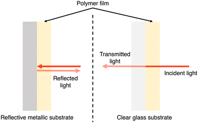 | ||
| Fig. 23 Schematic representation of the impact a reflective metallic substrate (left) and clear glass substrate (right) has on light transmitted through a polymer film. | ||
7.7. Post-processing of photocatalyst films: plasma treatment
Alkyl side-chains are commonly used in the development of solution processable organic conjugated materials, however, their hydrophobicity results in poor water wettability of the resultant material which negatively influences photocatalytic hydrogen evovlution.189 However, these hydrophobic alkyl side-chains can be transformed into hydrophilic groups by post-processing films with Ar plasma.49 This was demonstrated for drop-cast films of the dodecyl functionalised solution processable polymer FS-5Dodec (Fig. 20). The films were prepared on frosted glass slides and were then treated with Ar plasma for a specified time. The Ar plasma was believed to functionalize the dodecyl side-chains with hydrophilic functional groups including: carboxylates, ketones, and hydroxyl.49 Longer treatment times generally correlated with smaller water contact angles, with smaller contact angles being associated with improved water wettability. An optimum treatment time of 20 minutes with the Ar plasma was found, in which an 8-fold enhancement of the HER was observed, in which the rate increased from 135.8 to 1131.3 μmol h−1 g−1 (5 vol% TEA, >420 nm, 300 W Xe light source) and was accompanied by a decrease in the water contact angle from 109° to 43°. However, treatment times exceeding 20 minutes were found to lower the rate from this maximum value, with longer treatment times correlating with a lower HERs. This decrease in photocatalytic performance was believed to be due to damage to the polymer films, potentially through the formation of fluorenone defects which will contribute to reduced charge transport within the polymer films.49,1907.8. Composite films with inorganic semiconductors
Compared to PNPs, there are surprisingly few reports of heterojunction and composite film photocatalysts for hydrogen evolution.191 However, that is not to say that there have not been examples demonstrated, for example Wei et al. prepared a polymer–TiO2 film heterojunction photocatalyst.191 They coated TiO2 films with the carboxylic acid functionalised soluble polymer PDBCOOH (Fig. 20) by immersion of substrate in to the polymer solution. The carboxylic acid is believed to anchor the polymer to the TiO2 film, strengthening the interaction between PDBCOOH and TiO2.191 They found that their composite films outperformed single-component films of either PDBCOOH or TiO2, with the best performing composite demonstrating a promising HER 11.9 mmol h−1 m−2 (0.57 M AA, ≥420 nm, 300 W Xe light source).191 When considering the success of heterojunctions in the development of PNPs there is a clear opportunity for the expansion of this success into the development of multi-component films.7.9. Preparation of films of insoluble materials: drop-casting
Insoluble materials, unlike conjugated polymers with solubilising side-chains, cannot easily form homogeneous films but have nonetheless been frequently used to prepare film-type photocatalysts. For example, Cooper and co-workers prepared films of the insoluble FS-COF (Fig. 20) by film drop-casting from dilute N,N-dimethylformamide (DMF) suspensions onto glass substrates from a dilute suspension.176 After being functionalized with Pt and successive drop-casting cycles, a maximum HER of 24.9 mmol h−1 m−2 (8 wt% Pt, 0.1 M AA, >420 nm, 300 W Xe light source) was achieved by FS-COF.176 Similarly, Liu and co-workers processed the insoluble linear conjugated polymer BSO2-EDOT (Fig. 20) into a film by drop-casting from a suspension in N-methyl-2-pyrrolidone (NMP) onto glass substrates.35 The BSO2-EDOT film demonstrated an excellent HER of 132.2 mmol h−1 m−2 (0.47 M AA, >420 nm, 300 W Xe light source).35 These, and other examples, provide evidence that solubility may not be necessary to develop effective film-type photocatalysts on substrates (see Table 3). However, they often require excessive quantities of toxic solvents, such as DMF140,176 or NMP,35 to adequately suspend the material for drop-casting.192 Compounding the issue of excessive quantities of toxic solvents with the inhomogeneity of the resultant films would prove to be problematic for large scale photoreactors.7.10. Films of insoluble materials: flexible substrates
The preparation of film-type devices for photocatalysis by filtration through membrane filters has recently gained attention. Xu and co-workers prepared a film-type device by filtering a suspension of CTF nanosheets, 2D-TPs (Fig. 20), through a nylon membrane which evolved hydrogen at a steady rate of 135.2 mmol h−1 m−2 (3 wt% Pt, 10 vol% TEOA, >420 nm, 300 W Xe light source).50 While not reported for the film of 2D-TPs, the suspension of this material was able to perform OWS with a STH of 0.35%, which opens a potential usage for OWS film-type devices prepared from OSCs.50 Xu and co-worker later demonstrated another film-type device prepared by this filtration method using the zwitterionic COF ZVCOF-1 (Fig. 20) which demonstrated an outstanding HER of 402.1 mmol h−1 m−2 (1 wt% Pt, 1 M AA, >420 nm, 300 W Xe light source).179 This relatively simple processing method could provide a niche for the development of film-type devices due to the substrate flexibility and porosity afforded, however, the longevity of the device may need to be considered due to the potential issue of photocatalyst adherence to the substrate.187 Alternatively, non-woven fabrics have also been explored, in which the molecular OSC photocatalyst perylene tetracarboxylic acid (PTA, Fig. 20(e)) was used to prepare a film-type device (Fig. 24 inset).171 The molecular catalyst was spread on the non-woven fabric from a dilute aqueous suspension, followed by drying to immobilise the film. The resultant device evolved hydrogen at a steady rate of 8.0 mmol h−1 m−2 (4.6 wt% Pt, 0.2 M AA, AM1.5G, 300 W Xe light source).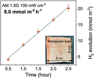 | ||
| Fig. 24 Photocatalytic rate of PTA film prepared on non-woven fabric (inset). Reprinted under CC-BY 4.0 License.171 | ||
7.11. Bottom-up approaches to film-type device processing
In 2021, Hu et al. prepared a free-standing, semicrystalline CTF film photocatalyst, CTF-HUST-film (Fig. 25), by a controlled polymerisation at the liquid–air interface by an aliphatic amine-assisted interface polymerization.180 Polymerising at the liquid–air interface, a substrate-free film was synthesised with control of the film thickness by varying the monomer feed concentration, with higher feed concentrations leading to thicker films.180CTF-HUST-film (thickness of ∼500 nm) was loaded to a glass slide before testing for sacrificial hydrogen evolution. CTF-HUST-film demonstrated a relatively modest HER of 5.4 mmol h−1 m−2 (2 wt% Pt, 10 vol% TEOA, >420 nm, 300 W Xe light source).180 Furthermore, the activity decreased upon extended testing, with rates decreasing after 50 hours and were not recoverable after replacing the SED solution.180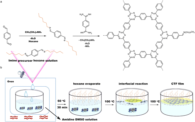 | ||
| Fig. 25 Interfacial polymerisation of the CTF-HUST-film by Hu et al. Reprinted under CC-BY 4.0 License.180 | ||
Another bottom-up approach to film-type photocatalyst devices was recently reported by Tan and co-workers in which they grew the film directly from a functionalised glass substrate surface.181 This was realised by firstly functionalising the surface with amino groups by treating glass substrates with 3-aminopropyltriethoxysilane, which allowed for aldehyde monomers to be anchored to the substrate surface via a Schiff base reaction.181 Polymerisation of the CTF then proceeded by a Schiff base pathway.181 After loading with Pt, the most active polymer thin film, CTF-TPA-Film-5 (Fig. 26) evolved hydrogen at an excellent rate of 213.3 mmol h−1 m−2 (6 wt% Pt, 10 vol% TEOA, >420 nm, 300 W Xe light source).181 However, no discussion on the integrity of the film after photocatalysis was provided, that is to say that there could be some form of breakaway of the film from the substrate.181
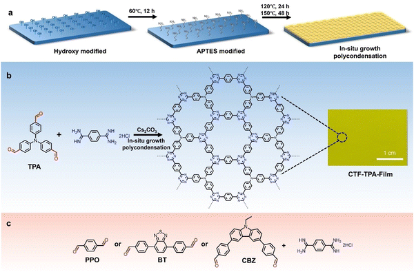 | ||
| Fig. 26 (a) Reaction steps of self-assembly monolayer to continuous CTF films. (b) The condensation reaction for CTF-TPA-Film, and optical picture of continuous CTF-TPA-Film grown on glass slide. (c) Monomer building blocks used in the study. Figure adapted from ref. 181 Copyright 2023, Wiley-VCH GmbH. | ||
7.12. Scaled-up reactors utilising supports
Domen and co-workers demonstrated in 2021 how scaled-up photoreactors could be feasibly utilised to produce hydrogen by photocatalytic OWS; whereby they presented an incredible 100 m2 reactor which operated continuously for several months using a SrTiO3:Al photocatalyst.193 However, this system possessed a modest STH of 0.76%, which is much lower than the 5–10% necessary for commercial viability.193 Nonetheless, this example provides a positive outlook for the usage of scale-up photoreactors for green hydrogen production. OSC photocatalysts have also been utilised in scale-up photoreactors for hydrogen evolution which utilised sunlight as the energy source, however, these systems required sacrificial agents as they could not perform OWS.Schröder et al. prepared an early example in which they demonstrated a 1 m2 panel photoreactor consisting of platinum functionalised mesoporous carbon nitride (Pt@mg-CN) suspended in 10 vol% TEOA.194 This photoreactor possessed an average area normalised HER of 0.08 L h−1 m−2 using sunlight.194 However, this dropped to 0.04 L h−1 m−2 when repeated one month later.194 These rates were considered low compared to their lab scale reactor (0.42 L h−1 m−2) under identical conditions. The lower rate was attributed to lower photocatalyst concentration in the scaled-up reactor, photocatalyst sedimentation which could not be re-suspended by the pump, and filtering of UV light by the polymer window.194 Undeterred, Schröder et al. prepared another scaled-up reactor in which the Pt@mg-CN was immobilised on stainless steel plates by drop-casting and adhered to the substrate using Nafion.195 This Pt@mg-CN reactor demonstrated an average sacrificial HER of 0.22 L m−2 h−1 (10 vol% TEOA) over a 30-day period.195 Unsurprisingly, the HER observed by this reactor varied with light intensity and reactor temperature.195 Later, Woods et al. prepared a photoreactor from glass fibres coated with soluble linear polymer FS-TEG (Fig. 20) in a cylindrical glass container.43 Mirrors were used to direct light at the reactor to increase incidence light.43 This photoreactor developed hydrogen at an average rate of 0.94 L h−1 m−2 (5 vol% TEA) on what was described as a “largely overcast day”.43 Whilst as a demonstration of their potential for large scale application, their use of sacrificial agents is an aspect that cannot be overlooked, especially given the success of some scaled-up inorganic based panel reactors which have demonstrated overall water splitting.196 More recently, Zhou et al. prepared a 0.705 m × 0.705 m panel reactor using HOF-H4TBAPy (Fig. 27), in which HOF-H4TBAPy was bonded to cellulose-based non-woven fibres to create a flexible film-type device.182 Using this scaled-up photoreactor under simulated sunlight they expected that their photoreactor could evolve hydrogen at a rate of 1 mol day−1 m−2 based on 9 hours of sunlight per day.182
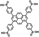 | ||
| Fig. 27 Structure of HOF-H4TBAPy.182 | ||
8. Conclusions, outlook, and opportunities
The processing of organic semiconductors into more sophisticated forms, such as PNPs, nanofibers, and films, has been demonstrated as an effective method of improving the efficiency of photocatalytic hydrogen evolution, compared to their bulk counterparts. This boost to efficiency is expected to not only improve the hydrogen production of the photocatalysts but will also be expected to provide the added benefit of lower reactor running costs. PNPs in particular have demonstrated huge strides in development since the early reports by Tian and co-workers.90 These impressive enhancements include EQEs exceeding 80%123,147 and sacrificial mass normalised HERs in excess of 300 mmol h−1 g−1 having been reported.109 However, real world utility must be considered and, unfortunately, many of these PNP systems still suffer from stability and recyclability issues, with most systems reporting deactivation over relatively short periods (hours to days), often due to the effects of aggregation. Furthermore, due to being in suspension their recyclability is rather poor, as filtration or centrifugation is required to recover the material, which can be both time consuming and wasteful.163,197 Finally, the influence of surfactants further confounds the use of PNPs as they been demonstrated to improve stability but also decrease photocatalytic performance. While significant steps have been taken to improve understanding of the influence of surfactants on hydrogen evolution PNPs, further study is clearly necessary to fully understand the involvement of surfactants in PNP systems.Nanofibers, while being one of the most underreported classes of processed materials, possesses a diverse array of processing methods for OSCs for photocatalytic hydrogen evolution. The broad collection of methods but limited application means that there is still a substantial volume of chemical space to still be explored. Therefore, there is significant potential for future research into this class of material. Nevertheless, like PNPs, nanofibers are utilised in suspension and, therefore, possess similar limitations to PNPs. Yet, nanofibers still have some of their own merits over PNPs, for example, the crystallinity afforded by CNP-f greatly influences the photocatalytic performance of the material compared to the amorphous analogue CNP-s. Electrospinning certainly warrants further exploration for photocatalytic materials due its high potential and the synthetic control afforded.
Film-type devices present an opportunity for the realisation of scaled up systems due to their simple scalability, recyclability, and reactor designs. However, compared to suspension based systems such as PNPs, there has been limited research performed and they have often been reported as an afterthought to exemplify how materials could be utilised. Standardisation of film photocatalysts, like much of the photocatalyst field, is an ongoing issue, with various substrates (glass, Nylon, Pt foil, Si), deposition methods (spin-coating, drop-casting, filtration, in situ growth), film thicknesses, and film homogeneity being studied with little comparison or discussion on the influence on photocatalytic performance. There are many opportunities for further research of photocatalyst films, such as detailed studies on the impact of substrates and deposition methods on photocatalytic performance. Furthermore, surface texturing of the films could be explored which has been demonstrated to improve performance in OPVs through improved light harvesting,198 additionally, this would provide the secondary benefit of increasing surface functionality. Another opportunity which has received surprisingly little attention given the extensive application in PNPs and nanofibers is the development of multi-component semiconductor films. The development of such films, given the simplicity of preparing films by drop-casting, for instance, could be a simple route to efficient film photocatalysts. Furthermore, the pairing of soluble organic photocatalysts for hydrogen evolution with inorganic oxygen evolution catalysts, such as WO3 or BiVO4,199 could provide a simple approach to forming a direct Z-scheme film type device. Alternatively, the modular design of photocatalytic films could provide a useful route to effective Z-scheme type systems in which the hydrogen evolution and oxygen evolution film photocatalysts are spatially separated and connected only by some redox shuttle, such as IO3−/I−.200 Such a photoreactor could allow for hydrogen and oxygen to be collected individually, thus increasing purity, lowering costs, and reducing the risks associated with oxyhydrogen. Moreover, planar photoreactors can be conveniently orientated to track the daily movement of the sun to maximise harvesting of solar energy.201 A similar system has been demonstrated by the so-called “hydrogen farm project” which evolved spatially separated hydrogen and oxygen using a redox mediated oxygen photocatalyst and a hydrogen evolving electrocatalyst, thus providing some foundations for this reactor design.202
Huge strides have been demonstrated by OSCs for photocatalytic hydrogen evolution within the relatively short time since the early reports of PNPs in 2016,90 nanofibers in 2017,159 and films in 2017.169 These developments have demonstrated huge increases in efficiency and show real promise for the future of organic photocatalysts. However, they still, unfortunately, have only been demonstrated under sacrificial conditions. Further research is necessary to develop organic photocatalysts that can perform OWS from which the knowledge obtained from these studies can be applied to maximise the efficiency of OWS photocatalysts and, hopefully, be used for real world application. However, the issues related to reactor design is one that still needs to be considered carefully for commercial viability and, rather than demonstrating lab scale marvels, should be the overall target for future research.
New opportunities have arisen from interfacing organic semiconductors with natural systems, such as enzymes,118 and cells.203 Here, controlling the interface is of upmost importance to enable effective charge transfer and processing of the OSC plays an important role in this. Other applications, such as hydrogen peroxide production,204 carbon dioxide conversion,205,206 nitrogen fixation,207 and organic transformations also require control over the interface and interaction with substrates, thus processing is expected to enhance the activity. Examples of hydrogen peroxide production with Pdots,208 as well as carbon dioxide reduction have been reported209 and we expect many more studies to follow on from here given the importance of processing.
Data availability
No new primary research results have been included and no new data was generated or analysed as part of this review.Conflicts of interest
There are no conflicts of interest to declare.Acknowledgements
R. S. S. thanks the University of Strathclyde for financial support through The Strathclyde Chancellor's Fellowship Scheme.References
- K. T. Møller, T. R. Jensen, E. Akiba and H.-W. Li, Prog. Nat. Sci.: Mater. Int., 2017, 27, 34–40 CrossRef.
- R. Moradi and K. M. Groth, Int. J. Hydrogen Energy, 2019, 44, 12254–12269 CrossRef CAS.
- I. Staffell, D. Scamman, A. Velazquez Abad, P. Balcombe, P. E. Dodds, P. Ekins, N. Shah and K. R. Ward, Energy Environ. Sci., 2019, 12, 463–491 RSC.
- Q. Wang and K. Domen, Chem. Rev., 2020, 120, 919–985 CrossRef CAS.
- V. Hasija, A. Kumar, A. Sudhaik, P. Raizada, P. Singh, Q. Van Le, T. T. Le and V.-H. Nguyen, Environ. Chem. Lett., 2021, 19, 2941–2966 CrossRef CAS.
- X. Yang and D. Wang, ACS Appl. Energy Mater., 2018, 1, 6657–6693 CrossRef CAS.
- Y. Wang, A. Vogel, M. Sachs, R. S. Sprick, L. Wilbraham, S. J. A. Moniz, R. Godin, M. A. Zwijnenburg, J. R. Durrant, A. I. Cooper and J. Tang, Nat. Energy, 2019, 4, 746–760 CrossRef CAS.
- S. Nishioka, F. E. Osterloh, X. Wang, T. E. Mallouk and K. Maeda, Nat. Rev. Methods Primers, 2023, 3, 42 CrossRef CAS.
- J. Zhang and X. Wang, Angew. Chem., Int. Ed., 2015, 54, 7230–7232 CrossRef CAS.
- C. M. Aitchison and R. S. Sprick, Nanoscale, 2021, 13, 634–646 RSC.
- S. Alam, V. Nádaždy, T. Váry, C. Friebe, R. Meitzner, J. Ahner, A. Anand, S. Karuthedath, C. S. P. De Castro, C. Göhler, S. Dietz, J. Cann, C. Kästner, A. Konkin, W. Beenken, A. M. Anton, C. Ulbricht, A. Sperlich, M. D. Hager, U. Ritter, F. Kremer, O. Brüggemann, U. S. Schubert, D. A. M. Egbe, G. C. Welch, V. Dyakonov, C. Deibel, F. Laquai and H. Hoppe, J. Mater. Chem. C, 2021, 9, 14463–14489 RSC.
- A. Fujishima and K. Honda, Nature, 1972, 238, 37–38 CrossRef CAS.
- H. Lyu, T. Hisatomi, Y. Goto, M. Yoshida, T. Higashi, M. Katayama, T. Takata, T. Minegishi, H. Nishiyama, T. Yamada, Y. Sakata, K. Asakura and K. Domen, Chem. Sci., 2019, 10, 3196–3201 RSC.
- T. Takata, J. Jiang, Y. Sakata, M. Nakabayashi, N. Shibata, V. Nandal, K. Seki, T. Hisatomi and K. Domen, Nature, 2020, 581, 411–414 CrossRef CAS.
- Y. Liu, B. Li and Z. Xiang, Small, 2021, 17, e2007576 CrossRef.
- H. Zhang, J. Liu and L. Jiang, Nanotechnology, 2022, 33, 322001 CrossRef CAS.
- P. Zhou, I. A. Navid, Y. Ma, Y. Xiao, P. Wang, Z. Ye, B. Zhou, K. Sun and Z. Mi, Nature, 2023, 613, 66–70 CrossRef CAS.
- C. B. Honsberg and S. G. Bowden, Photovoltaics Education Website, https://www.pveducation.org/pvcdrom/appendices/standard-solar-spectra (accessed February 2024).
- A. Amirjani, N. B. Amlashi and Z. S. Ahmadiani, ACS Appl. Nano Mater., 2023, 6, 9085–9123 CrossRef CAS.
- S. Yanagida, A. Kabumoto, K. Mizumoto, C. Pac and K. Yoshino, J. Chem. Soc., Chem. Commun., 1985, 474–475 RSC.
- S. Matsuoka, H. Fujii, T. Yamada, C. Pac, A. Ishida, S. Takamuku, M. Kusaba, N. Nakashima and S. Yanagida, J. Phys. Chem., 1991, 95, 5802–5808 CrossRef CAS.
- S. Matsuoka, T. Kohzuki, Y. Kuwana, A. Nakamura and S. Yanagida, J. Chem. Soc., Perkin Trans. 2, 1992, 679–685 RSC.
- S. Yanagida, T. Ogata, Y. Kuwana, Y. Wada, K. Murakoshi, A. Ishida, S. Takamuku, M. Kusaba and N. Nakashima, J. Chem. Soc., Perkin Trans. 2, 1996, 1963–1969 RSC.
- X. Wang, K. Maeda, A. Thomas, K. Takanabe, G. Xin, J. M. Carlsson, K. Domen and M. Antonietti, Nat. Mater., 2009, 8, 76–80 CrossRef CAS.
- A. Wadsworth, Z. Hamid, J. Kosco, N. Gasparini and I. McCulloch, Adv. Mater., 2020, 32, e2001763 CrossRef.
- X. Chen, K. Geng, R. Liu, K. T. Tan, Y. Gong, Z. Li, S. Tao, Q. Jiang and D. Jiang, Angew. Chem., Int. Ed., 2020, 59, 5050–5091 CrossRef CAS.
- K. Geng, T. He, R. Liu, S. Dalapati, K. T. Tan, Z. Li, S. Tao, Y. Gong, Q. Jiang and D. Jiang, Chem. Rev., 2020, 120, 8814–8933 CrossRef CAS.
- R. Sun and B. Tan, Chem. – Eur. J., 2023, 29, e202203077 CrossRef CAS.
- J. M. Lee and A. I. Cooper, Chem. Rev., 2020, 120, 2171–2214 CrossRef CAS.
- C. M. Aitchison, M. Sachs, M. A. Little, L. Wilbraham, N. J. Brownbill, C. M. Kane, F. Blanc, M. A. Zwijnenburg, J. R. Durrant, R. S. Sprick and A. I. Cooper, Chem. Sci., 2020, 11, 8744–8756 RSC.
- H. Yang, C. Li, T. Liu, T. Fellowes, S. Y. Chong, L. Catalano, M. Bahri, W. Zhang, Y. Xu, L. Liu, W. Zhao, A. M. Gardner, R. Clowes, N. D. Browning, X. Li, A. J. Cowan and A. I. Cooper, Nat. Nanotechnol., 2023, 18, 307–315 CrossRef CAS.
- Y. Zhu, Z. Zhang, W. Si, Q. Sun, G. Cai, Y. Li, Y. Jia, X. Lu, W. Xu, S. Zhang and Y. Lin, J. Am. Chem. Soc., 2022, 144, 12747–12755 CrossRef CAS.
- Z. Zhang, W. Si, B. Wu, W. Wang, Y. Li, W. Ma and Y. Lin, Angew. Chem., Int. Ed., 2022, 61, e202114234 CrossRef CAS.
- X. Li, P. M. Maffettone, Y. Che, T. Liu, L. Chen and A. I. Cooper, Chem. Sci., 2021, 12, 10742–10754 RSC.
- Z. R. Tan, Y. Q. Xing, J. Z. Cheng, G. Zhang, Z. Q. Shen, Y. J. Zhang, G. Liao, L. Chen and S. Y. Liu, Chem. Sci., 2022, 13, 1725–1733 RSC.
- Y. Liu, J. Wu and F. Wang, Appl. Catal., B, 2022, 307, 121144 CrossRef CAS.
- Z. A. Lan, G. Zhang, X. Chen, Y. Zhang, K. A. I. Zhang and X. Wang, Angew. Chem., Int. Ed., 2019, 58, 10236–10240 CrossRef CAS.
- C. Han, S. Xiang, X. Feng, P. Zhang, Y. Ren, C. Zhang, X. Wang and J. X. Jiang, Chem. Commun., 2023, 59, 6235–6238 RSC.
- X. Chi, Q. Chen, Z. A. Lan, X. Zhang, X. Chen and X. Wang, Chem. – Eur. J., 2023, 29, e202202734 CrossRef CAS.
- Z. A. Lan, M. Wu, Z. Fang, X. Chi, X. Chen, Y. Zhang and X. Wang, Angew. Chem., Int. Ed., 2021, 60, 16355–16359 CrossRef CAS.
- A. Vogel, M. Forster, L. Wilbraham, C. L. Smith, A. J. Cowan, M. A. Zwijnenburg, R. S. Sprick and A. I. Cooper, Faraday Discuss., 2019, 215, 84–97 RSC.
- Z. Luo, X. Chen, Y. Hu, X. Chen, W. Lin, X. Wu and X. Wang, Angew. Chem., Int. Ed., 2023, 62, e202304875 CrossRef CAS.
- D. J. Woods, S. A. J. Hillman, D. Pearce, L. Wilbraham, L. Q. Flagg, W. Duffy, I. McCulloch, J. R. Durrant, A. A. Y. Guilbert, M. A. Zwijnenburg, R. S. Sprick, J. Nelson and A. I. Cooper, Energy Environ. Sci., 2020, 13, 1843–1855 RSC.
- R. Li, C. Zhang, C.-X. Cui, Y. Hou, H. Niu, C.-H. Tan, X. Yang, F. Huang, J.-X. Jiang and Y. Zhang, Polymer, 2022, 240, 124509 CrossRef CAS.
- Q. Li, K.-H. Li, L.-N. Liu, Z.-X. Xue, Z.-W. Xu and W.-S. Li, ACS Appl. Polym. Mater., 2023, 5, 8570–8578 CrossRef CAS.
- W.-R. Wang, J. Li, Q. Li, Z.-W. Xu, L.-N. Liu, X.-Q. Chen, W.-J. Xiao, J. Yao, F. Zhang and W.-S. Li, J. Mater. Chem. A, 2021, 9, 8782–8791 RSC.
- M. H. Elsayed, M. Abdellah, A. Z. Alhakemy, I. M. A. Mekhemer, A. E. A. Aboubakr, B. H. Chen, A. Sabbah, K. H. Lin, W. S. Chiu, S. J. Lin, C. Y. Chu, C. H. Lu, S. D. Yang, M. G. Mohamed, S. W. Kuo, C. H. Hung, L. C. Chen, K. H. Chen and H. H. Chou, Nat. Commun., 2024, 15, 707 CrossRef CAS.
- X. Lin, Y. Liang, Z. Hu, X. Zhang, Y. Liang, Z. Hu, F. Huang and Y. Cao, Nanomaterials, 2022, 12, 1535 CrossRef CAS.
- R. S. Sprick, K. J. Cheetham, Y. Bai, J. Alves Fernandes, M. Barnes, J. W. Bradley and A. I. Cooper, J. Mater. Chem. A, 2020, 8, 7125–7129 RSC.
- C. Wang, P. Lyu, Z. Chen and Y. Xu, J. Am. Chem. Soc., 2023, 145, 12745–12754 CrossRef CAS.
- O. V. Mikhnenko, P. W. M. Blom and T.-Q. Nguyen, Energy Environ. Sci., 2015, 8, 1867–1888 RSC.
- M. Sachs, H. Cha, J. Kosco, C. M. Aitchison, L. Francas, S. Corby, C. L. Chiang, A. A. Wilson, R. Godin, A. Fahey-Williams, A. I. Cooper, R. S. Sprick, I. McCulloch and J. R. Durrant, J. Am. Chem. Soc., 2020, 142, 14574–14587 CrossRef CAS.
- E. McQueen, Y. Bai and R. S. Sprick, Nanomaterials, 2022, 12, 4299 CrossRef CAS.
- Y. Tao, B. McCulloch, S. Kim and R. A. Segalman, Soft Matter, 2009, 5, 4219–4230 RSC.
- Y. Tamai, H. Ohkita, H. Benten and S. Ito, J. Phys. Chem. Lett., 2015, 6, 3417–3428 CrossRef CAS.
- K. Oka, B. Winther-Jensen and H. Nishide, Adv. Energy Mater., 2021, 11, 2003724 CrossRef CAS.
- L. Y. Kunz, B. T. Diroll, C. J. Wrasman, A. R. Riscoe, A. Majumdar and M. Cargnello, Energy Environ. Sci., 2019, 12, 1657–1667 RSC.
- A. Visan, J. R. van Ommen, M. T. Kreutzer and R. G. H. Lammertink, Ind. Eng. Chem. Res., 2019, 58, 5349–5357 CrossRef CAS.
- Z. Wang, T. Hisatomi, R. Li, K. Sayama, G. Liu, K. Domen, C. Li and L. Wang, Joule, 2021, 5, 344–359 CrossRef CAS.
- C. M. Aitchison and I. McCulloch, Chem. Mater., 2024, 36, 1781–1792 CrossRef CAS.
- A. Liu, L. Gedda, M. Axelsson, M. Pavliuk, K. Edwards, L. Hammarström and H. Tian, J. Am. Chem. Soc., 2021, 143, 2875–2885 CrossRef CAS.
- J. J. P. Thompson, M. Gerhard, G. Witte and E. Malic, npl 2D Mater. Appl., 2023, 7, 69 CrossRef CAS.
- J. Ran, J. Zhang, J. Yu, M. Jaroniec and S. Z. Qiao, Chem. Soc. Rev., 2014, 43, 7787–7812 RSC.
- J. Yang, D. Wang, H. Han and C. Li, Acc. Chem. Res., 2013, 46, 1900–1909 CrossRef CAS.
- J. Kosco, M. Sachs, R. Godin, M. Kirkus, L. Francas, M. Bidwell, M. Qureshi, D. Anjum, J. R. Durrant and I. McCulloch, Adv. Energy Mater., 2018, 8, 1802181 CrossRef.
- J. Kosco and I. McCulloch, ACS Energy Lett., 2018, 3, 2846–2850 CrossRef CAS.
- R. Binjhade, R. Mondal and S. Mondal, J. Environ. Chem. Eng., 2022, 10, 107746 CrossRef CAS.
- A. Valverde-González, C. G. López Calixto, M. Barawi, M. Gomez-Mendoza, V. A. de la Peña O’Shea, M. Liras, B. Gómez-Lor and M. Iglesias, ACS Appl. Energy Mater., 2020, 3, 4411–4420 CrossRef.
- Y. Bai, C. Li, L. Liu, Y. Yamaguchi, M. Bahri, H. Yang, A. Gardner, M. A. Zwijnenburg, N. D. Browning, A. J. Cowan, A. Kudo, A. I. Cooper and R. S. Sprick, Angew. Chem., Int. Ed., 2022, 61, e202201299 CrossRef CAS.
- Y. Pellegrin and F. Odobel, C. R. Chim, 2017, 20, 283–295 CrossRef CAS.
- M. Qureshi and K. Takanabe, Chem. Mater., 2016, 29, 158–167 CrossRef.
- L. Zhou, C. Rao, Y. Pang, D. Yang, H. Lou and X. Qiu, Langmuir, 2023, 39, 3431–3438 CrossRef CAS.
- H. Kisch and D. Bahnemann, J. Phys. Chem. Lett., 2015, 6, 1907–1910 CrossRef CAS.
- H. Kisch, Angew. Chem., Int. Ed., 2013, 52, 812–847 CrossRef CAS.
- M. V. Pavliuk, S. Wrede, A. Liu, A. Brnovic, S. Wang, M. Axelsson and H. Tian, Chem. Soc. Rev., 2022, 51, 6909–6935 RSC.
- S. A. J. Hillman, R. S. Sprick, D. Pearce, D. J. Woods, W. Y. Sit, X. Shi, A. I. Cooper, J. R. Durrant and J. Nelson, J. Am. Chem. Soc., 2022, 144, 19382–19395 CrossRef CAS.
- D. M. Fabian, S. Hu, N. Singh, F. A. Houle, T. Hisatomi, K. Domen, F. E. Osterloh and S. Ardo, Energy Environ. Sci., 2015, 8, 2825–2850 RSC.
- Z. Wang, C. Li and K. Domen, Chem. Soc. Rev., 2019, 48, 2109–2125 RSC.
- S. Canellas, M. Nuno and E. Speckmeier, Nat. Commun., 2024, 15, 307 CrossRef CAS.
- S. Cao and L. Piao, Angew. Chem., Int. Ed., 2020, 59, 18312–18320 CrossRef CAS.
- H. Kisch, Angew. Chem., Int. Ed., 2010, 49, 9588–9589 CrossRef CAS.
- S. Kang, T. W. Yoon, G.-Y. Kim and B. Kang, ACS Appl. Nano Mater., 2022, 5, 17436–17460 CrossRef CAS.
- L. Guo, J. Ge and P. Wang, Photochem. Photobiol., 2018, 94, 916–934 CrossRef CAS.
- L. R. MacFarlane, H. Shaikh, J. D. Garcia-Hernandez, M. Vespa, T. Fukui and I. Manners, Nat. Rev. Mater., 2020, 6, 7–26 CrossRef.
- J. Yu, Y. Rong, C. T. Kuo, X. H. Zhou and D. T. Chiu, Anal. Chem., 2017, 89, 42–56 CrossRef CAS.
- J. Pecher and S. Mecking, Chem. Rev., 2010, 110, 6260–6279 CrossRef CAS.
- D. Tuncel and H. V. Demir, Nanoscale, 2010, 2, 484–494 RSC.
- M. Yu, W. Zhang, Z. Guo, Y. Wu and W. Zhu, Angew. Chem., Int. Ed., 2021, 60, 15590–15597 CrossRef CAS.
- K. N. Schwarz, S. B. Farley, T. A. Smith and K. P. Ghiggino, Nanoscale, 2015, 7, 19899–19904 RSC.
- L. Wang, R. Fernandez-Teran, L. Zhang, D. L. Fernandes, L. Tian, H. Chen and H. Tian, Angew. Chem., Int. Ed., 2016, 55, 12306–12310 CrossRef CAS.
- P. B. Pati, G. Damas, L. Tian, D. L. A. Fernandes, L. Zhang, I. B. Pehlivan, T. Edvinsson, C. M. Araujo and H. Tian, Energy Environ. Sci., 2017, 10, 1372–1376 RSC.
- P.-J. Tseng, C.-L. Chang, Y.-H. Chan, L.-Y. Ting, P.-Y. Chen, C.-H. Liao, M.-L. Tsai and H.-H. Chou, ACS Catal., 2018, 8, 7766–7772 CrossRef CAS.
- A. Liu, C.-W. Tai, K. Holá and H. Tian, J. Mater. Chem. A, 2019, 7, 4797–4803 RSC.
- Z. Hu, Z. Wang, X. Zhang, H. Tang, X. Liu, F. Huang and Y. Cao, iScience, 2019, 13, 33–42 CrossRef CAS.
- P. Zhao, L. Wang, Y. Wu, T. Yang, Y. Ding, H. G. Yang and A. Hu, Macromolecules, 2019, 52, 4376–4384 CrossRef CAS.
- X. Zhang, F. Shen, Z. Hu, Y. Wu, H. Tang, J. Jia, X. Wang, F. Huang and Y. Cao, ACS Sustatainable Chem. Eng., 2019, 7, 4128–4135 CrossRef CAS.
- C.-L. Chang, W.-C. Lin, C.-Y. Jia, L.-Y. Ting, J. Jayakumar, M. H. Elsayed, Y.-Q. Yang, Y.-H. Chan, W.-S. Wang, C.-Y. Lu, P.-Y. Chen and H.-H. Chou, Appl. Catal., B, 2020, 268, 1–7 CrossRef.
- H. Yang, X. Li, R. S. Sprick and A. I. Cooper, Chem. Commun., 2020, 56, 6790–6793 RSC.
- M. H. Elsayed, M. Abdellah, Y. H. Hung, J. Jayakumar, L. Y. Ting, A. M. Elewa, C. L. Chang, W. C. Lin, K. L. Wang, M. Abdel-Hafiez, H. W. Hung, M. Horie and H. H. Chou, ACS Appl. Mater. Interfaces, 2021, 13, 56554–56565 CrossRef CAS.
- A. M. Elewa, J. Jayakumar, Y.-W. Huang, M. H. Elsayed, C.-L. Chang, L.-Y. Ting, W.-C. Lin, C.-C. Chueh and H.-H. Chou, J. Environ. Chem. Eng., 2022, 10, 106927 CrossRef CAS.
- A. M. Elewa, C.-Y. Liao, W.-L. Li, I. M. A. Mekhemer and H.-H. Chou, Macromolecules, 2022, 56, 1352–1361 CrossRef.
- A. Liu, S. Wang, H. Song, Y. Liu, L. Gedda, K. Edwards, L. Hammarstrom and H. Tian, Phys. Chem. Chem. Phys., 2023, 25, 2935–2945 RSC.
- A. Brnovic, L. Hammarström and H. Tian, J. Phys. Chem. C, 2023, 127, 12631–12639 CrossRef CAS.
- J. Kosco, M. Bidwell, H. Cha, T. Martin, C. T. Howells, M. Sachs, D. H. Anjum, S. Gonzalez Lopez, L. Zou, A. Wadsworth, W. Zhang, L. Zhang, J. Tellam, R. Sougrat, F. Laquai, D. M. DeLongchamp, J. R. Durrant and I. McCulloch, Nat. Mater., 2020, 19, 559–565 CrossRef CAS.
- J. Kosco, S. Gonzalez-Carrero, C. T. Howells, T. Fei, Y. Dong, R. Sougrat, G. T. Harrison, Y. Firdaus, R. Sheelamanthula, B. Purushothaman, F. Moruzzi, W. Xu, L. Zhao, A. Basu, S. De Wolf, T. D. Anthopoulos, J. R. Durrant and I. McCulloch, Nat. Energy, 2022, 7, 340–351 CrossRef CAS.
- A. Dolan, J. M. de la Perrelle, T. D. Small, E. R. Milsom, G. F. Metha, X. Pan, M. R. Andersson, D. M. Huang and T. W. Kee, ACS Appl. Nano Mater., 2022, 5, 12154–12164 CrossRef CAS.
- S. An, S. Z. Hassan, J. W. Jung, H. Cha, C. H. Cho and D. S. Chung, Small Methods, 2022, 6, e2200010 CrossRef.
- J. Kosco, S. Gonzalez-Carrero, C. T. Howells, W. Zhang, M. Moser, R. Sheelamanthula, L. Zhao, B. Willner, T. C. Hidalgo, H. Faber, B. Purushothaman, M. Sachs, H. Cha, R. Sougrat, T. D. Anthopoulos, S. Inal, J. R. Durrant and I. McCulloch, Adv. Mater., 2021, 34, e2105007 CrossRef.
- Y. Liang, T. Li, Y. Lee, Z. Zhang, Y. Li, W. Si, Z. Liu, C. Zhang, Y. Qiao, S. Bai and Y. Lin, Angew. Chem., Int. Ed., 2023, 62, e202217989 CrossRef CAS.
- Y. Yang, D. Li, P. Wang, X. Zhang, H. Zhang, B. Du, C. Guo, T. Wang and D. Liu, Polymer, 2022, 244, 124667 CrossRef CAS.
- Y. Yang, D. Li, J. Cai, H. Wang, C. Guo, S. Wen, W. Li, T. Wang and D. Liu, Adv. Funct. Mater., 2023, 33, 2209643 CrossRef CAS.
- S. Wen, Y. Yang, J. Cai, C. Guo, H. Wang, C. Chen, Y. Liu, X. Zhang, D. Li, Z. Chen, W. Li, T. Wang and D. Liu, ACS Catal., 2023, 13, 12730–12736 CrossRef CAS.
- C. M. Aitchison, R. S. Sprick and A. I. Cooper, J. Mater. Chem. A, 2019, 7, 2490–2496 RSC.
- H. Yang, H. Amari, L. Liu, C. Zhao, H. Gao, A. He, N. D. Browning, M. A. Little, R. S. Sprick and A. I. Cooper, Nanoscale, 2020, 12, 24488–24494 RSC.
- A. Holmes, E. Deniau, C. Lartigau-Dagron, A. Bousquet, S. Chambon and N. P. Holmes, ACS Nano, 2021, 15, 3927–3959 CrossRef CAS.
- K. Landfester, Adv. Mater., 2001, 13, 765–768 CrossRef CAS.
- Y. Zhang, P. Baran Pati and H. Tian, Adv. Matter. Lett., 2018, 9, 326–330 CrossRef.
- M. V. Pavliuk, M. Lorenzi, D. R. Morado, L. Gedda, S. Wrede, S. H. Mejias, A. Liu, M. Senger, S. Glover, K. Edwards, G. Berggren and H. Tian, J. Am. Chem. Soc., 2022, 144, 13600–13611 CrossRef CAS.
- W.-C. Lin, M. H. Elsayed, J. Jayakumar, L.-Y. Ting, C.-L. Chang, A. M. Elewa, W.-S. Wang, C.-C. Chung, C.-Y. Lu and H.-H. Chou, Int. J. Hydrogen Energy, 2020, 45, 32072–32081 CrossRef CAS.
- C. J. Brinker, Y. Lu, A. Sellinger and H. Fan, Adv. Mater., 1999, 11, 579–585 CrossRef CAS.
- Y. Guo, J. Sun, T. Guo, Y. Liu and Z. Yao, Angew. Chem., Int. Ed., 2024, 63, e202319664 CrossRef CAS.
- K. M. Pustulka, A. R. Wohl, H. S. Lee, A. R. Michel, J. Han, T. R. Hoye, A. V. McCormick, J. Panyam and C. W. Macosko, Mol. Pharmaceutics, 2013, 10, 4367–4377 CrossRef CAS.
- W. Zhang, M. Yu, T. Liu, M. Cong, X. Liu, H. Yang, Y. Bai, Q. Zhu, S. Zhang, H. Gu, X. Wu, Z. Zhang, Y. Wu, H. Tian, X. Li, W.-H. Zhu and A. I. Cooper, Nat. Synth., 2024, 3, 595–605 CrossRef.
- P. Mondelli, P. Kaienburg, F. Silvestri, R. Scatena, C. Welton, M. Grandjean, V. Lemaur, E. Solano, M. Nyman, P. N. Horton, S. J. Coles, E. Barrena, M. Riede, P. Radaelli, D. Beljonne, G. N. M. Reddy and G. Morse, J. Mater. Chem. A, 2023, 11, 16263–16278 RSC.
- S. Subianto, R. Balu, L. de Campo, A. Sokolova, N. K. Dutta and N. R. Choudhury, ACS Appl. Mater. Interfaces, 2018, 10, 44116–44125 CrossRef CAS.
- N. P. Holmes, S. Chambon, A. Holmes, X. Xu, K. Hirakawa, E. Deniau, C. Lartigau-Dagron and A. Bousquet, Curr. Opin. Colloid Interface Sci., 2021, 56, 101511 CrossRef CAS.
- S. An, Z. Wu, H. Jeong, J. Lee, S. Y. Jeong, W. Lee, S. Kim, J. W. Han, J. Lim, H. Cha, H. Y. Woo and D. S. Chung, Small, 2023, 19, e2204905 CrossRef.
- R. S. Sprick, B. Bonillo, M. Sachs, R. Clowes, J. R. Durrant, D. J. Adams and A. I. Cooper, Chem. Commun., 2016, 52, 10008–10011 RSC.
- R. S. Sprick, Y. Bai, A. A. Y. Guilbert, M. Zbiri, C. M. Aitchison, L. Wilbraham, Y. Yan, D. J. Woods, M. A. Zwijnenburg and A. I. Cooper, Chem. Mater., 2018, 31, 305–313 CrossRef.
- M. Sachs, R. S. Sprick, D. Pearce, S. A. J. Hillman, A. Monti, A. A. Y. Guilbert, N. J. Brownbill, S. Dimitrov, X. Shi, F. Blanc, M. A. Zwijnenburg, J. Nelson, J. R. Durrant and A. I. Cooper, Nat. Commun., 2018, 9, 4968 CrossRef.
- J. Pei, H. Li, S. Zhuang, D. Zhang and D. Yu, Catalysts, 2023, 13, 1402 CrossRef CAS.
- Y. Liu, H. Wu and Q. Wang, J. Mater. Chem. A, 2023, 11, 21470–21497 RSC.
- Z. Lin and J. Guo, Macromol. Rapid Commun., 2023, 44, e2200719 CrossRef.
- S. Yang, Y. Gong, J. Zhang, L. Zhan, L. Ma, Z. Fang, R. Vajtai, X. Wang and P. M. Ajayan, Adv. Mater., 2013, 25, 2452–2456 CrossRef CAS.
- K. L. Corp and C. W. Schlenker, J. Am. Chem. Soc., 2017, 139, 7904–7912 CrossRef CAS.
- K. Schwinghammer, M. B. Mesch, V. Duppel, C. Ziegler, J. Senker and B. V. Lotsch, J. Am. Chem. Soc., 2014, 136, 1730–1733 CrossRef CAS.
- Y. Lu, D. Chu, M. Zhu, Y. Du and P. Yang, Phys. Chem. Chem. Phys., 2015, 17, 17355–17361 RSC.
- H. Ou, L. Lin, Y. Zheng, P. Yang, Y. Fang and X. Wang, Adv. Mater., 2017, 29, 1700008 CrossRef.
- J.-H. Zhang, M.-J. Wei, Z.-W. Wei, M. Pan and C.-Y. Su, ACS Appl. Nano Mater., 2020, 3, 1010–1018 CrossRef CAS.
- C. Wang, H. Zhang, W. Luo, T. Sun and Y. Xu, Angew. Chem., Int. Ed., 2021, 60, 25381–25390 CrossRef CAS.
- Z. Fan, K. Nomura, M. Zhu, X. Li, J. Xue, T. Majima and Y. Osakada, Commun. Chem., 2019, 2, 55 CrossRef.
- L. Li, Y. Zhu, N. Gong, W. Zhang, W. Peng, Y. Li, F. Zhang and X. Fan, Int. J. Hydrogen Energy, 2020, 45, 2689–2698 CrossRef CAS.
- R. Chen, Y. Wang, Y. Ma, A. Mal, X. Y. Gao, L. Gao, L. Qiao, X. B. Li, L. Z. Wu and C. Wang, Nat. Commun., 2021, 12, 1354 CrossRef CAS.
- X. Li, K. Nomura, A. Guedes, T. Goto, T. Sekino, M. Fujitsuka and Y. Osakada, ACS Omega, 2022, 7, 7172–7178 CrossRef CAS.
- X. Ren, C. Li, W. Kang, H. Li, N. Ta, S. Ye, L. Hu, X. Wang, C. Li and Q. Yang, CCS Chem., 2022, 4, 2429–2439 CrossRef CAS.
- J.-Z. Cheng, Z.-R. Tan, Y.-Q. Xing, Z.-Q. Shen, Y.-J. Zhang, L.-L. Liu, K. Yang, L. Chen and S.-Y. Liu, J. Mater. Chem. A, 2021, 9, 5787–5795 RSC.
- C. Li, J. Liu, H. Li, K. Wu, J. Wang and Q. Yang, Nat. Commun., 2022, 13, 2357 CrossRef CAS.
- Z. L. Shaw, S. Kuriakose, S. Cheeseman, M. D. Dickey, J. Genzer, A. J. Christofferson, R. J. Crawford, C. F. McConville, J. Chapman, V. K. Truong, A. Elbourne and S. Walia, Nat. Commun., 2021, 12, 3897 CrossRef CAS.
- D. Pathak, A. Sharma, D. P. Sharma and V. Kumar, Appl. Surf. Sci. Adv., 2023, 18, 100471 CrossRef.
- J. Yoon and J. M. Kim, Macromol. Chem. Phys., 2008, 209, 2194–2203 CrossRef CAS.
- L. B. Huang, W. Xu and J. Hao, Small, 2017, 13, 170929 Search PubMed.
- Y. Wang, T. Yokota and T. Someya, NPG Asia Mater., 2021, 13, 1–22 CrossRef CAS.
- J. Tian, Y. Zhang, L. Du, Y. He, X. H. Jin, S. Pearce, J. C. Eloi, R. L. Harniman, D. Alibhai, R. Ye, D. L. Phillips and I. Manners, Nat. Chem., 2020, 12, 1150–1156 CrossRef CAS.
- Y. Zhang, J. Tian, H. Shaikh, H. K. MacKenzie, Y. He, C. Zhao, S. Lei, Y. Ren and I. Manners, J. Am. Chem. Soc., 2023, 145, 22539–22547 CrossRef CAS.
- X.-H. Jin, M. B. Price, J. R. Finnegan, C. E. Boott, J. M. Richter, A. Rao, S. M. Menke, R. H. Friend, G. R. Whittell and I. Manners, Science, 2018, 360, 897–900 CrossRef CAS.
- Y. Zhang, H. Shaikh, A. J. Sneyd, J. Tian, J. Xiao, A. Blackburn, A. Rao, R. H. Friend and I. Manners, J. Am. Chem. Soc., 2021, 143, 7032–7041 CrossRef CAS.
- Y. Sun, H. Wallrabe, S. A. Seo and A. Periasamy, ChemPhysChem, 2010, 12, 462–474 CrossRef.
- S. Ghosh, D. Rashmi, S. Bera and R. N. Basu, Int. J. Hydrogen Energy, 2019, 44, 13262–13272 CrossRef CAS.
- J. Wang, J. Cong, H. Xu, J. Wang, H. Liu, M. Liang, J. Gao, Q. Ni and J. Yao, ACS Sustatainable Chem. Eng., 2017, 5, 10633–10639 CrossRef CAS.
- S. Ghosh, S. Bera, S. Bysakh and R. N. Basu, ACS Appl. Mater. Interfaces, 2017, 9, 33775–33790 CrossRef CAS.
- Z. Liu, X. Zhang, S. Poyraz, S. P. Surwade and S. K. Manohar, J. Am. Chem. Soc., 2010, 132, 13158–13159 CrossRef CAS.
- C. Clavero, Nat. Photonics, 2014, 8, 95–103 CrossRef CAS.
- T. Hisatomi and K. Domen, Nat. Catal., 2019, 2, 387–399 CrossRef CAS.
- F. E. Osterloh, Chem. Soc. Rev., 2013, 42, 2294–2320 RSC.
- F. Yang, Y. Huang, Y. Li and Y. Li, npj Flex, Electron, 2021, 5, 30 CAS.
- J. Yang, Z. Zhao, S. Wang, Y. Guo and Y. Liu, Chem, 2018, 4, 2748–2785 CAS.
- K. Fukuda and T. Someya, Adv. Mater., 2017, 29, 161128 CrossRef.
- D. Zhang, B. Fan, L. Ying, N. Li, C. J. Brabec, F. Huang and Y. Cao, SusMat, 2021, 1, 4–23 CrossRef CAS.
- D. J. Woods, R. S. Sprick, C. L. Smith, A. J. Cowan and A. I. Cooper, Adv. Energy Mater., 2017, 7, 1700479 CrossRef.
- Y. Hu, Y. Liu, J. Wu, Y. Li, J. Jiang and F. Wang, ACS Appl. Mater. Interfaces, 2021, 13, 42753–42762 CrossRef CAS.
- Y. Guo, Q. Zhou, J. Nan, W. Shi, F. Cui and Y. Zhu, Nat. Commun., 2022, 13, 2067 CrossRef CAS.
- C. L. Chang, W. C. Lin, L. Y. Ting, C. H. Shih, S. Y. Chen, T. F. Huang, H. Tateno, J. Jayakumar, W. Y. Jao, C. W. Tai, C. Y. Chu, C. W. Chen, C. H. Yu, Y. J. Lu, C. C. Hu, A. M. Elewa, T. Mochizuki and H. H. Chou, Nat. Commun., 2022, 13, 5460 CrossRef CAS.
- F. Y. Cao, C. L. Huang, T. Y. Cheng, H. J. Cheng, T. K. Wu and Y. J. Cheng, ACS Macro Lett., 2023, 12, 468–474 CrossRef CAS.
- W. C. Lin, C. L. Chang, C. H. Shih, W. C. Lin, Z. Yu Lai, J. W. Chang, L. Y. Ting, T. F. Huang, Y. E. Sun, H. Y. Huang, Y. T. Lin, J. J. Liu, Y. H. Wu, Y. T. Tseng, Y. R. Zhuang, B. H. Li, A. C. Su, C. H. Yu, C. W. Chen, K. H. Lin, U. S. Jeng and H. H. Chou, Small, 2023, 19, 0230615 Search PubMed.
- R. J. Lyons, Y. Yang, E. McQueen, L. Luo, A. I. Cooper, M. A. Zwijnenburg and R. S. Sprick, Adv. Energy Mater., 2024, 14, 2303680 CrossRef CAS.
- X. Wang, L. Chen, S. Y. Chong, M. A. Little, Y. Wu, W. H. Zhu, R. Clowes, Y. Yan, M. A. Zwijnenburg, R. S. Sprick and A. I. Cooper, Nat. Chem., 2018, 10, 1180–1189 CrossRef CAS.
- Q. Zuo, T. Liu, C. Chen, Y. Ji, X. Gong, Y. Mai and Y. Zhou, Angew. Chem., Int. Ed., 2019, 58, 10198–10203 CrossRef CAS.
- G. Shu, Y. Li, Z. Wang, J.-X. Jiang and F. Wang, Appl. Catal., B, 2020, 261, 118230 CrossRef CAS.
- Z. Zhang and Y. Xu, J. Am. Chem. Soc., 2023, 46, 25222–25232 CrossRef.
- X. Hu, Z. Zhan, J. Zhang, I. Hussain and B. Tan, Nat. Commun., 2021, 12, 6596 CrossRef CAS.
- Y. Guo, X. Hu, R. Sun, X. Wang and B. Tan, ChemSusChem, 2023, e202300759 CrossRef CAS.
- Q. Zhou, Y. Guo and Y. Zhu, Nat. Catal., 2023, 6, 574–584 CrossRef CAS.
- K. Choudhary, A. X. Chen, G. M. Pitch, R. Runser, A. Urbina, T. J. Dunn, M. Kodur, A. T. Kleinschmidt, B. G. Wang, J. A. Bunch, D. P. Fenning, A. L. Ayzner and D. J. Lipomi, ACS Appl. Mater. Interfaces, 2021, 13, 51436–51446 CrossRef CAS.
- K. Zhao, X. Yu, R. Li, A. Amassian and Y. Han, J. Mater. Chem. C, 2015, 3, 9842–9848 RSC.
- T.-Q. Nguyen, R. Y. Yee and B. J. Schwartz, J. Photochem. Photobiol., A, 2001, 144, 21–30 CrossRef CAS.
- Y. Yao, H. Dong and W. Hu, Polym. Chem., 2013, 4, 5197–5205 RSC.
- Y. Liu, M. O. Coppens and Z. Jiang, Chem. Soc. Rev., 2021, 50, 11747–11765 RSC.
- J. Yang, S. He, H. Liu, E. Jaatinen, E. Waclawik, J. Quan, S. Sarina, C. He, S. Huang, H. Zhu and M. Wu, J. Mater. Chem. A, 2023, 11, 4751–4757 RSC.
- B. Meng, H. Song, X. Chen, Z. Xie, J. Liu and L. Wang, Macromolecules, 2015, 48, 4357–4363 CrossRef CAS.
- M. Kuik, G. J. A. H. Wetzelaer, J. G. Laddé, H. T. Nicolai, J. Wildeman, J. Sweelssen and P. W. M. Blom, Adv. Funct. Mater., 2011, 21, 4502–4509 CrossRef CAS.
- G. Wei, F. Niu, Z. Wang, X. Liu, S. Feng, K. Hu, X. Gong and J. Hua, Mater. Today Chem., 2022, 26, 101075 CrossRef CAS.
- A. Figoli, T. Marino, S. Simone, E. Di Nicolò, X. M. Li, T. He, S. Tornaghi and E. Drioli, Green Chem., 2014, 16, 4034–4059 RSC.
- H. Nishiyama, T. Yamada, M. Nakabayashi, Y. Maehara, M. Yamaguchi, Y. Kuromiya, Y. Nagatsuma, H. Tokudome, S. Akiyama, T. Watanabe, R. Narushima, S. Okunaka, N. Shibata, T. Takata, T. Hisatomi and K. Domen, Nature, 2021, 598, 304–307 CrossRef CAS.
- M. Schröder, K. Kailasam, S. Rudi, K. Fündling, J. Rieß, M. Lublow, A. Thomas, R. Schomäcker and M. Schwarze, RSC Adv., 2014, 4, 50017–50026 RSC.
- M. Schröder, K. Kailasam, J. Borgmeyer, M. Neumann, A. Thomas, R. Schomäcker and M. Schwarze, Energy Technol., 2015, 3, 1014–1017 CrossRef.
- Y. Goto, T. Hisatomi, Q. Wang, T. Higashi, K. Ishikiriyama, T. Maeda, Y. Sakata, S. Okunaka, H. Tokudome, M. Katayama, S. Akiyama, H. Nishiyama, Y. Inoue, T. Takewaki, T. Setoyama, T. Minegishi, T. Takata, T. Yamada and K. Domen, Joule, 2018, 2, 509–520 CrossRef CAS.
- Z. Kuspanov, B. Bakbolat, A. Baimenov, A. Issadykov, M. Yeleuov and C. Daulbayev, Sci. Total Environ, 2023, 885, 163914 CrossRef CAS.
- R. Zeng, L. Zhu, M. Zhang, W. Zhong, G. Zhou, J. Zhuang, T. Hao, Z. Zhou, L. Zhou, N. Hartmann, X. Xue, H. Jing, F. Han, Y. Bai, H. Wu, Z. Tang, Y. Zou, H. Zhu, C. C. Chen, Y. Zhang and F. Liu, Nat. Commun., 2023, 14, 4148 CrossRef CAS.
- Y. Bai, K. Nakagawa, A. J. Cowan, C. M. Aitchison, Y. Yamaguchi, M. A. Zwijnenburg, A. Kudo, R. S. Sprick and A. I. Cooper, J. Mater. Chem. A, 2020, 8, 16283–16290 RSC.
- K. Murofushi, K. Ogawa, H. Suzuki, R. Sakamoto, O. Tomita, K. Kato, A. Yamakata, A. Saeki and R. Abe, J. Mater. Chem. A, 2021, 9, 11718–11725 RSC.
- B. A. Pinaud, J. D. Benck, L. C. Seitz, A. J. Forman, Z. Chen, T. G. Deutsch, B. D. James, K. N. Baum, G. N. Baum, S. Ardo, H. Wang, E. Miller and T. F. Jaramillo, Energy Environ. Sci., 2013, 6, 1983–2002 RSC.
- Y. Zhao, C. Ding, J. Zhu, W. Qin, X. Tao, F. Fan, R. Li and C. Li, Angew. Chem., Int. Ed., 2020, 59, 9653–9658 CrossRef CAS.
- Y. Yang, L. N. Liu, H. Tian, A. I. Cooper and R. S. Sprick, Energy Environ. Sci., 2023, 16, 4305–4319 RSC.
- S. Chai, X. Chen, X. Zhang, Y. Fang, R. S. Sprick and X. Chen, Environ. Sci. Nano., 2022, 9, 2464–2469 RSC.
- Z. Fu, A. Vogel, M. A. Zwijnenburg, A. I. Cooper and R. S. Sprick, J. Mater. Chem. A, 2021, 9, 4291–4296 RSC.
- M. M. Kandy, Sustainable Energy Fuels, 2020, 4, 469–484 RSC.
- J. Byun and K. A. I. Zhang, Mater. Horiz., 2020, 7, 15–31 RSC.
- S. Wang, G. Kumar and H. Tian, Sol. RRL, 2022, 6, 2200755 CrossRef CAS.
- B. Cai, M. Axelsson, S. Zhan, M. V. Pavliuk, S. Wang, J. Li and H. Tian, Angew. Chem., Int. Ed., 2023, 62, e202312276 CrossRef CAS.
| This journal is © The Royal Society of Chemistry 2024 |


