 Open Access Article
Exploring the persistence of the fluorinated thiolate 2,3,5,6-S(C6F4H-4) motif to establish πF–πF stacking in metal complexes: a crystal engineering perspective†
Everardo
Jaime-Adán
 a,
Juan Manuel
Germán-Acacio
 *b,
José Carlos
Páez-Franco
 b,
Victor H.
Lara
c,
Viviana
Reyes-Marquez
 d and
David
Morales-Morales
 *a
*a
aInstituto de Química, Universidad Nacional Autónoma de México, Circuito Exterior, Ciudad Universitaria, Ciudad de México, C. P. 04510, Mexico. E-mail: damor@unam.mx
bRed de Apoyo a la Investigación, Universidad Nacional Autónoma de México-CIC, Instituto Nacional de Ciencias Médicas y Nutrición SZ, C. P.14000, Ciudad de México, Mexico. E-mail: jmga@cic.unam.mx
cUniversidad Autonoma Metropolitana, Iztapalapa, Av. San Rafael Atlixco No. 186, Col. Vicentina, 09340 Ciudad de México, Mexico
dDepartamento de Ciencias Químico-Biológicas, Universidad de Sonora, Luis Encinas y Rosales s/n, Hermosillo C.P. 83000, Sonora, Mexico
First published on 15th August 2024
Abstract
π–π stacking interactions are versatile because they are involved in many processes, such as protein folding, DNA stacking, and drug recognition. However, from the point of view of crystal engineering, there is an incipient knowledge of its exploitation. A comparison of these interactions with hydrogen bonds shows a huge difference in their employment as a reliable non-covalent interaction. And different reasons can be listed to explain why hydrogen bonding can be considered a more robust interaction than π−π stacking. For instance, hydrogen bonds encompass a wide energy range (25–40 kJ mol−1). From this, these interactions can be classified as strong, moderate, and weak. Hence, the first two can be considered highly to moderately directional to be exploited in crystal engineering. This aspect is relevant for them to be used in a relatively reliably way in this area of supramolecular chemistry. On the other hand, in the case of π−π stacking, the energy range is 0–10 kJ mol−1, thus implying that hydrogen bonds or any other energetically more robust contact would predominate in the competition for establishing packing interactions in a given arrangement. In this sense, if stacking is pretended to be exploited from the point of view of crystal engineering, one of the points that must be ensured is that this interaction will be the one energetically predominant. However, although there are other factors to consider, it seems that energetics is the dominant one. In this line, our research group has obtained and studied many single-crystalline structures of coordination and organometallic compounds containing fluorinated thiolates. This being particularly true in the case of the thiolate 2,3,5,6-S(C6F4H-4) bound to different metals, where it has been observed that they preferentially tend to establish πF–πF stacking interactions, results that have been reported in several papers. Thus, from this perspective, we have explored, using ConQuest (CCDC) a number of structures to observe how feasible is to find stacking in coordination and organometallic compounds containing the thiolate 2,3,5,6-S(C6F4H-4).
1. Introduction
Crystal engineering is a branch of supramolecular chemistry that focuses on obtaining crystalline materials exhibiting extended arrangements (molecular networks) using tectons (building blocks) with recognition sites capable of forming covalent or non-covalent interactions to attain the desired molecular array.1Thus, the appropriate use of bonding interactions is essential for assembling these molecular aggregates. For which there is a wide variety of interactions; many being isotropic or anisotropic and exhibiting a broad difference in the range of energies.2
For instance, organic crystal engineering (OCE) is interested in assembling molecular crystals with organic tectons exploiting non-covalent bonds, mainly van der Waals forces and hydrogen bonds (neutral and charge-assisted).3,4 And covalent organic frameworks (COF) assemblies uses building blocks linked by covalent bonds that can be exploited in OCE.5 These supramolecular entities have high molecular ordering and well-defined porosities. Conversely, inorganic crystal engineering (ICE) employs transition metals and main group atoms since metal ions give more varied geometries uncommon in organic chemistry.6 It also introduces the metal's inherent properties, such as catalytic, photophysical, or magnetic attributes.7 From the ICE point of view, there are two approaches for forming supramolecular structures: one exploiting convergent ligands (coordination compounds) and divergent ligands (coordination networks), Fig. 1.8,9 In the latter case, it allows the formation of periodic coordination complexes (1D, 2D, 3D, cages, metallocycles).10–14 Also within this category we have metal–organic frameworks (MOFs).6,15,16
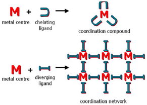 | ||
| Fig. 1 Schematic representation of the relationship between molecular (top) and periodical (bottom) coordination chemistry. Reproduced with permission of the Royal Society of Chemistry from ref. 9. | ||
Another approach (using coordination compounds) is to use tectons with a metallic center coordinated to a ligand containing functional groups that may form hydrogen bonds. The geometry adopted by the coordination compound will help to orient the ligand to another functional group, forming hydrogen bonds to give place to a network. This being referred as organic–inorganic hybrid materials, Fig. 2.17
 | ||
| Fig. 2 Schematic representation of the incorporation of metals into 1D hydrogen bonded-assemblies via coordination chemistry, or π-organometallic chemistry, and their relationship to the parent organic hydrogen-bonded assemblies and coordination polymers. Reproduced with permission of the Royal Society of Chemistry from ref. 17. | ||
This approach has several advantages over coordination networks that involve the incorporation of strong bonds (coordination) and the flexibility conferred by the hydrogen bonds (weaker interaction).18–20 A useful tool/resource that within the variety of non-covalent interactions used in supramolecular chemistry stands out as it is very directional and highly specific.6,21
The formation of compounds with strong bonds (covalent or coordinative) generally involves irreversible processes during self-assembly since forming these bonds is governed by ΔH. In hydrogen bonds, the ΔH and ΔS contributions are almost the same. Therefore, there should be a great deal of pre-organization in the system so that interactions can occur.22,23 The hydrogen bond is kinetically labile; that is, it can be cleaved or reformed depending on the system's requirements in the self-assembly processes.24 Molecularly ordered crystalline materials can be obtained through this interaction under mild self-assembly conditions (room temperature); forming coordination networks requires more drastic conditions (hydro- or solvothermal reactions). In this sense, reliable hydrogen bonds must be used to ensure the construction of the extended crystalline arrangement.25,26
Dance proposed (later modified by Brammer) a model of the regions or domains of these hybrid organic–inorganic materials, where hydrogen bonding can be exploited depending on the region of these complexes.21 Brammer refined this model, resolving some ambiguities in the Dance model, Fig. 3. The modified Brammer model is delimited into four regions: the metal domain (blue), the ligand domain (green), the periphery domain (red), and the environment domain (light blue). In the metal domain, the metal is part of the M–H⋯A hydrogen bond, where the donor is the M–H fragment (M = metal), and A is an acceptor. The formation of this bond is imminently dependent on the electronic properties of the metal. In the case of the ligand domain, the metal exerts an electronic influence on the formation of the hydrogen bond, where there are two possibilities: the metal can work as a donor M–D–H⋯A or the metal may act as an acceptor D–H⋯A–M. In both cases, the electronic properties can be modulated, the acidity in the first type or the basicity in the second. In the periphery domain, the electronic dependence of the metal is lower, and the outer part of the metal/coordination compound can interact with the environment domain. In this region (environment domain), the electronic influence of the metal fragment is almost null. Brammer has explained how these domains have been exploited to form interesting molecular arrangements linked by hydrogen bonds.6,21
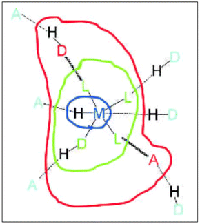 | ||
| Fig. 3 Domain model for hydrogen bonding involving metal complexes. Metal domain (blue); ligand domain (green); periphery domain (red); environment (cyan). Reproduced with permission of the Wiley from ref. 21. | ||
Thus, in this perspective, we look to perform an analysis using the data found in the Cambridge Structural Database (CSD, using Conquest)27 to explore the possibility of exploiting the formation of π–π stacking interactions. In this sense, it is necessary to remember what Aakeröy pointed out about a “supramolecular synthon” defined as a connector that binds molecules through non-covalent interactions.28 In this way, the “supramolecular synthons” describe molecular recognition events between the participating components that, during the self-assembly processes, will produce the desired crystalline arrangement. With this in mind, this analysis pretends to explore how reliable and robust these interactions are to be exploited in supramolecular chemistry.
2. Fundamentals and theoretical aspects of the π interactions
π interactions (mainly π−π stacking) have received less attention in their exploitation in crystal engineering than hydrogen bonding, especially because their nature still needs to be better understood. Nevertheless, π−π stacking interactions are involve in several important biological processes, like protein folding,29 DNA stacking,30 and drug recognition.31,32 Recently, it has been reported an Scopus analysis revealing an exponential increase in the number of titles, keywords, or abstracts including π–π interactions.33 The little interest shown by the crystal engineering community towards using this interaction is probably because their formation is so difficult to predict, as parameters such as force, geometric preferences, and substituent electronic influence need to be better understood. Energetically, a hydrogen bond is slightly stronger than a π–π interaction (25–40 kJ mol−1vs. 10 kJ mol−1).1,34 Therefore, studying π−π stackings can be a difficult task from an experimental point of view since these results depend on interpretation when secondary interactions and solvation effects can perturb the formation of this interaction.35 For these reasons, efforts to understand the fundamentals that define π−π interactions have been addressed using theoretical models.35,36For instance, Sanders and Hunter have proposed a model based on the competition of electrostatic forces and van der Waals contacts in a benzene-benzene dimeric system to explain the variety of geometries observed in the interactions and qualitatively predict the energies associated with each interaction.36 From these calculations, they found the preferred geometries in the interactions between benzene rings from an electrostatic interaction map in the function of their relative orientations. Electrostatic effects greatly dictate the geometrical preferences adopted in benzene dimers, and other forces such as induction, dispersion, and exchange-repulsion are irrelevant. However, Sherrill et al. have disputed this, mentioning that electrostatics effects are not dominant.35 But, since they are all significant, Sherrill suggested that electrostatic, dispersion, induction, and exchange-repulsion components must be considered.37
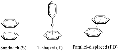
The geometric preferences of the π−π interactions in benzene dimers can be classified into three different configurations: sandwich (S) configuration when both benzenes sit on top of each other, T-shaped (T) when one benzene points to the center of the other, and parallel displaced (PD) that is reached from the sandwich configuration by parallel displacement of one ring away from the other, Fig. 4.10 There can be eclipsed and staggered arrangements within the S conformation, although the energetic differences between one and the other are insignificant.10
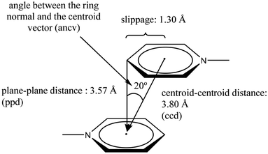
These three arrangements can be found in the crystalline state, thus raising a fundamental question seen from the discernment of crystal engineering: what defines any of these geometric conformations? The answer is probably related to energy. The balance of fundamental forces such as electrostatics, induction, dispersion, and exchange-repulsion can be responsible for the adopted geometric preference.35 In this sense, subtle modifications in the contribution of these forces can completely change the geometric conformation adopted; thus, the possibility of considering π−π interactions as a reliable and predictable working tool in crystal engineering can be difficult to handle. However, the substituent effect has been proposed as an efficient way to handle this situation. A suitable tuning in the ring's withdrawing/donating electronic properties has given excellent results.38,39 Electron-withdrawing substituents or heteroatoms within the ring make the aromatic system an electron-deficient center, favoring the S configuration because repulsive effects are reduced. Meanwhile, electron-donating substituents promote electron-rich aromatic rings, which disfavors the S configuration because repulsion effects are enhanced. The order of stability of the configuration S can be πpoor–πpoor > πpoor–πrich > πrich–πrich.38 Janiak explains that the S configuration is rare, and the PD arrangement is more frequent.38 Janiak has also established the geometric parameters to consider a stacking in systems containing pyridine rings attached to a metal center, Fig. 5.38 As can be observed, these parameters define both edges to consider an S or a PD configuration: centroid–centroid distance (ccd); plane–plane distance (ppd); angle between the ring normal and the centroid vector (ancv) (in our description, instead of using the ancv angle we use the plane–plane angle (ppa), since both are representative of the rotation between the rings involved); and slippage, Fig. 5. In this sense, within the search made in the CSD, we will stick to the limits of these parameters to consider that a genuine π−π stacking interaction has been established. Throughout the perspective, we will display the values of the parameters as follows: [operation symmetry; ccd Å; ppd Å; slippage Å; and ppa°]. These crystallographic parameters will be determined using the Olex 2, and Platon programs.40,41
3. Fluorination of ligands
The fluorination of molecules has been an excellent strategy for producing important physicochemical and biological improvements in different compounds. For instance, we have recently published the advantages of preparing fluorinated metallodrugs.42 In the case of metallodrugs, hurdles such as aqueous-solubility issues, low bioavailability, and short circulation time, can be circumvented by employing two strategies: design of novel metallodrug-delivering vehicles and the structural optimization of the ligand(s). In the latter case, substituting H atoms with F within the ligand can produce important modifications at the molecular and supramolecular level43,44 since F atoms participate in various non-covalent interactions, contributing greatly to crystal stabilization. Among these can be mentioned C–H⋯F–C, C–F⋯F–C, C–F⋯π, C–F⋯πF, C–F⋯M+, C–F⋯X (N, O, S, halogen), π−πF, and πF−πF.44–46Thus, introducing fluorine atoms in aromatic rings has proven to be an efficient way to have electron-deficient aromatic components that establish F⋯F contacts and πF−πF stacking.44,46,47 Much has been said about showing π−πF, and πF−πF interactions when they compete with hydrogen bonds since this interaction may be dominant in the packing array, relegating the stacking motif.48 If one wishes to exploit the π−π stacking as a “supramolecular synthon”, one must avoid stronger competitive interactions prevailing in the system.49
4. Previous contributions made by our research group
For over 20 years, our group has synthesized coordination and organometallic compounds with different metals containing fluorinated benzenethiolates (mono, di, tri, tetra, and pentafluorinated). In this sense, innumerable single-crystal structures have been obtained. The versatility shown by fluorinated benzethiolates has already been mentioned since these ligands can stabilize unusual geometries and high and low oxidation states.50 Moreover, their steric and electronic properties can be finely modulated by manipulating the content of fluorine atoms within the aromatic ring.50Our results show that the tetrafluorinated ligand 2,3,4,6-S(C6F4H-4) preferentially establishes πF–πF interactions. However, this has been observed less frequently in the pentafluorinated thiolate S(C6F5). In this regard, we have published some papers referring to this.
Initially, we observed that depending on the degree of fluorination in the thiolate ring, the compounds [Pt(II)(2,2′-bipy)(SRF)2] (bipy = bipyridine, R = (2,3,4,6-C6F4-4-H) or (C6F5); REF CODE: MIXFAB and MIXDUT), could establish πF–πF stacking interactions or not, Fig. 6.51 Complex MIXFAB presents an intra πF–πF stacking between rings C13–C18⋯C19–C24 with values of [+X, +Y, +Z, 3.478 Å; 3.397 Å; 0.749 Å; and 7.085°], and an inter πF–πF interaction between C13–C18⋯C19–C2 [−X, 1 − Y, 1 − Z, 3.899 Å; −3.667 Å; 1.323 Å; and 0.0°].
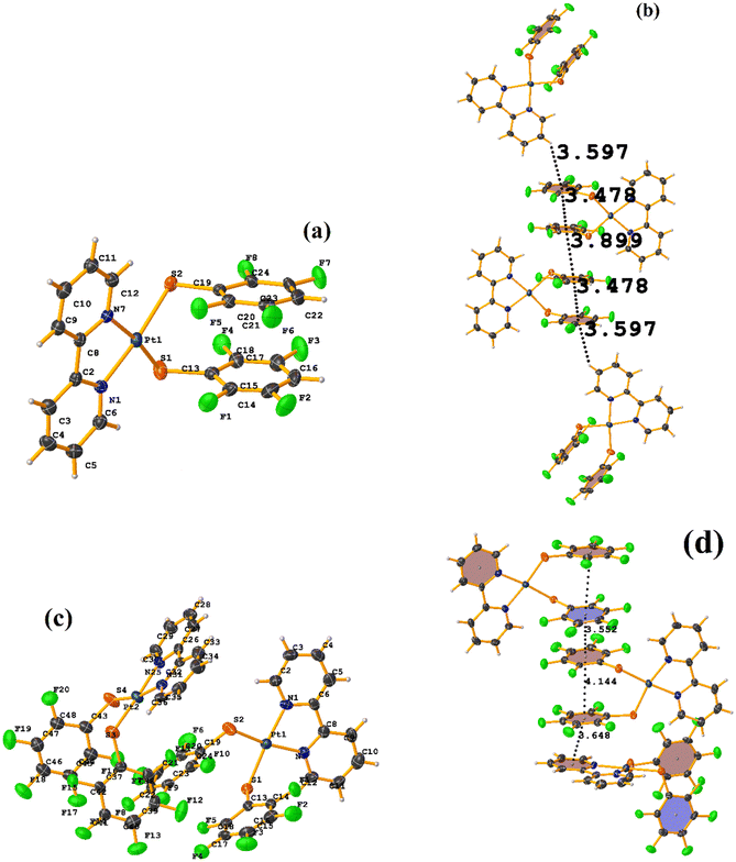 | ||
| Fig. 6 (a) Molecular structure of MIXFAB. (b) Stacking interactions of MIXFAB. (c) Molecular structure of MIXDUT. (d) Stacking interactions of MIXDUT. | ||
In general, in these complexes, having an extra F atom (pentafluorinated MIXDUT) limited the establishment of the interaction compared with the tetrafluorinated. In the case of the pentafluorinated complex an inter πF–πF interaction was observed between C13–C18⋯C37–C42 [−1/2 + X, 3/2 − Y, 1/2 + Z, 3.552 Å; 3.390 Å; 1.092 Å; and 0.581°] and no intra πF–πF stacking was noted. Similarly, a πF–π interaction was found between a pentafluorinated ring and the aryl of the 2,2′-bipy ligand i.e. C43–C48⋯N1/C2–C6 [+X, 1 + Y, +Z, 3.648 Å; 3.402 Å; 1.526 Å; and 6.672°]. It is proposed that this happens because when the 2,3,4,6-S(C6F4-H-4) fragments are stacked, the S atoms point in the opposite directions, allowing a positive dipole of one molecule to interact with the negative dipole of the other, fact that does not occur in S(C6F5).51
Specifically, in these tectons [Pt(II)(2,2′-bipy)(SRF)2], it was observed that πF–πF stacking interactions were preferentially established when tetrafluorinated thiolates were used instead of the pentafluorinated ones.
From this, we sought to test the robustness of these tectons to form πF–πF interaction, which now varies in certain aspects. In this way, complexes of the type [Pt(II)(1,10-phen)(SRF)2] (phen = phenanthroline, SRF = SC6H3-3,4-F2, 2,3,4,6-SC6F4-4-H, and SC6F5; REF CODE: LUQMIW, LUQMOC, and LUQMUI) were published,52 where although the crystalline packing was not described in deep detail, it was observed that stacking interactions were formed. It should be noted that there was a change in the chelating ligand (1,10-phen to 2,2′-bipy) to a ligand with a larger π surface area that can preferentially form π–π stacks.53,54 This is mentioned because, as indicated, the formation of the desired synthon depends on other competing interactions. In the case of LUQMIW (difluorinated), this tecton did not show the establishment of πF–πF stacking interactions.
On the other hand, the pentafluorinated thiolate compound (LUQMOC) has an intra πF–πF stacking between C17–C22⋯C11–C16 [+X, +Y, +Z, 3.600 Å; 1.337 Å; and adpp 4.249°], Fig. 7. There was also an inter πF–πF interaction between C17–C22⋯C11–C16 [1 − X, 2 − Y, 1 − Z, 3.990 Å; 1.813 Å; and 0.0°]. Contrary to the tetrafluorinated one (LUQMUI), where it was found a πF–πF intramolecular stacking C51–C56⋯C45–C50 [+X, +Y, +Z, 3.530 Å; 1.480 Å; and 2.221°], Fig. 7. It must be emphasized that the LUQMUI structure presents two crystallographically independent molecules. The other crystallographically independent molecule exhibits intermolecular πF–πF interactions C45–C50⋯C15–C20 [+X, 1 + Y, +Z, 3.546 Å; 1.290 Å; and 4.610°]. Interactions intra πF–π were also found between the tetrafluorinated ring and a phen fragment C45–C50⋯N10/C9–C14 [1 − X, 1 − Y, 1 − Z, 3.509 Å; 0.965 Å; and 6.214°]. Thus, πF–πF interactions prevailed despite the phen ligands favoring stacking due to their larger π surface area.53,54 Thus indicating that these interactions may persist even in competing interactions.
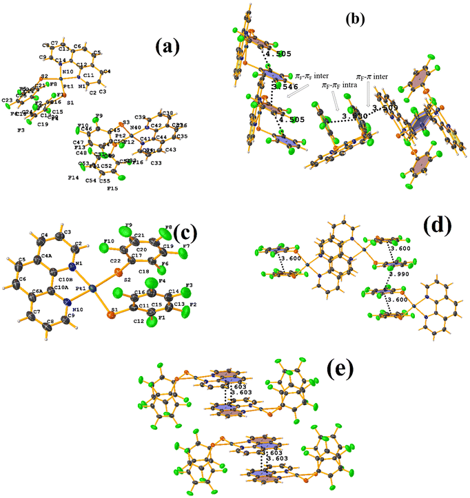 | ||
| Fig. 7 (a) Molecular structure of LUQMUI. (b) Stacking interactions of LUQMUI. (c) Molecular structure of LUQMOC. (d and e) Stacking interactions of MIXDUT. | ||
Based on these results, we wanted to continue exploiting this tecton but variying the metal to observe if the formation of the stacking persisted thus we synthesized complex [Pd(II)(1,10-phen)(SRF)2]. Most recently we reported the preparation of solvatomorphs of the type ([Pd(II)(1,10-phen)(2,3,4,6-SC6F4-4-H)2]·S, S = C6H6, C6H6Cl, and C6H6Br; REF CODE: DEQLUK, DEQMIZ, DEQMEV), solvate ([Pd(II)(1,10-phen)(SC6F5)2]·C6H6Br, REF CODE: DEQLOE), and non-solvated ([Pd(II)(1,10-phen)(2,3,4,6-SC6F4-4-H)2] REF CODE: HIHREX01).49 Unexpectedly, in this series of tectons, various solvatomorphs and solvates were preferentially crystallized, and the hypothesis of establishing stacked πF–πF interactions did not materialize compared with the same tecton but with Pt(II), where πF–πF interactions were established.
According to these three papers, it was observed that even when using a tecton with slightly modified characteristics to evaluate the persistence of πF–πF interactions, they were only detected in two of the three cases, being preferably established with thiolate 2,3,4,6-SC6F4-H-4. In this way, the question arises: is this a sufficiently robust and reliable ligand to establish πF–πF interactions regardless of the nature of the tecton's in a metal complex? Then, using the Cambridge Structural Database (CSD),27 the deposited structures were explored, looking for metal complexes including the thiolate 2,3,5,6-SC6F4-H-4 coordinated at least once. From this, each of the structures was analyzed, as shown next.
5. Results from CSD
Using Conquest (Version 2022.3.0) from the CSD (Version 5.43), we searched for tetrafluorinated thiolate 2,3,5,6-SC6F4-H-4 metal complexes using the label 4M. We found 87 crystal structures from which we obtained the π–π parameters using the PLATON software. As referenced above, we are interested in the πF–πF parameters centroid–centroid distance (ccd), plane–plane distance (ppd), slippage, and plane–plane angle (ppa). Of these parameters, we filter the results using ccd <4 Å and ppa <20°. Ending up with 51 crystal structures. Analysis of this group of structures will be discussed depending on the metal involved. As mentioned in section 2, the study to determine the stacking π–π interactions will use the crystallographic parameters [operation symmetry, ccd Å; ppd Å; slippage Å; and ppa°]. These will be obtained through the Olex 2, and Platon programs.40,41 The study of each structure will be made and discussed according to the metal atom involved, arranged alphabetically. Worth to mention that there will not be an exhaustive study of the secondary interactions, or any other contact involved in the analysis, even though they are important in molecular packing. Still, only the geometric parameters will be described. The results obtained from ConQuest from the CSD are shown in the ESI.† A discussion will be made at the end of all the structures corresponding to structures containing a particular metal atom. This will be done based on the results obtained through ConQuest. Additionally, the geometric parameters of the πF–πF interactions were corroborated using the Platon program.41 Each CIF will be analyzed individually to detect the desired interactions.6. πF–πF stacking analysis
Au metal complexes
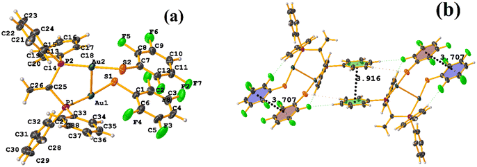
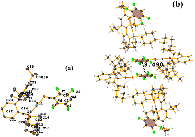
In this instance, two stacking πF–πF and π–π interactions were found. An intra πF–πF interaction, with the parameters found to be [+X, +Y, +Z, 3.707 Å; 3.400(4) Å; 1.378 Å; and 4.277°] between the rings C1–C6⋯C7–C12 and a π–π inter stacking between two rings of the μ-vdpp ligand, that was established between C19–C24⋯C19–C24 presenting the geometric parameters [1 − X, 1 − Y, −Z, 3.916(5) Å; 3.685(4) Å; 1.326 Å; and 0.0(4)°].
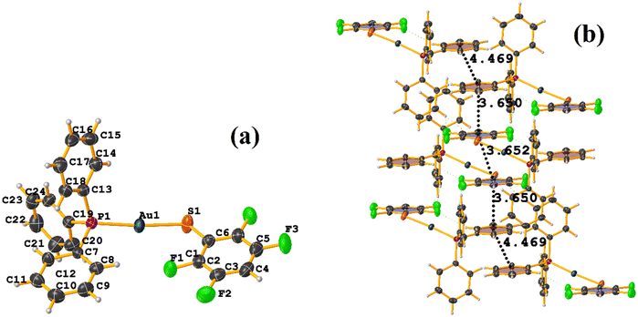
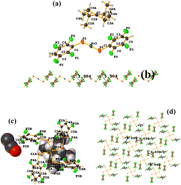
Both the ditopic (LOKWEO) and tetratopic (LOKVUD) molecules exhibit wind blade shapes that facilitate the formation of 1D and 2D networks. From the supramolecular point of view, propagation occurs predominantly through πF–πF interactions. Noteworthy the fact that even the presence of Et4N or EtOH perturbs the establishment of this interaction. LOKWEO structure exhibits πF–πF interstacking between the fluorinated rings of C1–C6⋯C1–C6 thiols [1 − X, −Y, −Z, 3.504 Å; 3.318(2) Å; 1.127 Å; and 0.00°]. In the case of LOKVUD, the following parameters were determined: C1A–C6A⋯C1B–C6B thiolates [−X, −Y, −Z, 3.636 Å; 1.426 Å; 3.346(3) Å; and 0.00°] and C1A–C6A⋯C1B–C6B thiolates [1 − X, −Y, 1 − Z, 3.645 Å; 3.412(3) Å; 1.282 Å; and 0.00°].
Cd metal complexes
It can be observed in the supramolecular structure that a 1D network is formed, which is directed by the Cd–S coordination bond, forming a chain. In this way, an intra πF–πF stacking is established, determined by the chain imposed by the coordination bond Cd–S. The geometrical parameters were found: C1–C6⋯C7–C12 [1 + X, +Y, +Z, 3.621(3) Å; 3.4218(19) Å; 1.186 Å; and 4.0(2)°].
Co metal complexes
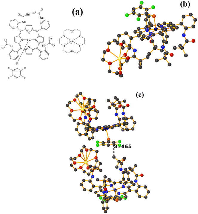
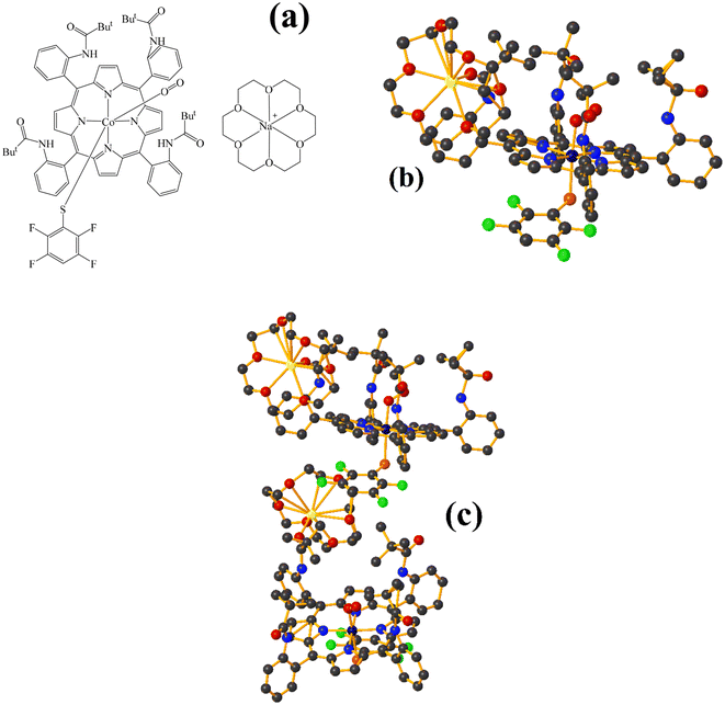
Fe metal complexes
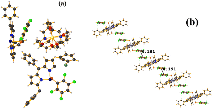
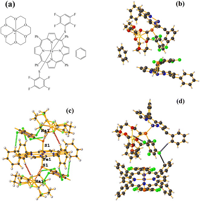
Supramolecularly it is observed that there is an S1⋯Na1 (red cotton balls, Fig. 17c) interaction between the S atom of the thiolate and the alkali metal of the cation [Na⊂18C6]+. This imposes the cation on both faces of the porphyrin, which prevents πF–πF stacking interactions from forming since several C–F⋯H–C interactions are established.
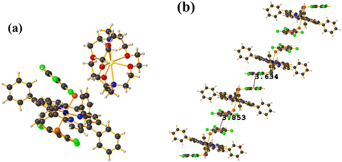
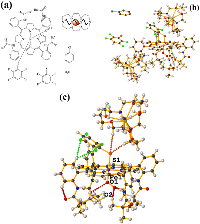
As seen in Fig. 18(b and c), it is observed that above the thiolate ring, there is the cryptand [K⊂222] stabilized by interactions of type C–H⋯F–C, S⋯H–C. This prevents stacking from being established. On the other side of the TPP− ligand face, the amide groups stabilize the Fe–O![[double bond, length as m-dash]](https://www.rsc.org/images/entities/char_e001.gif) O fragment through C–H⋯O contacts.
O fragment through C–H⋯O contacts.
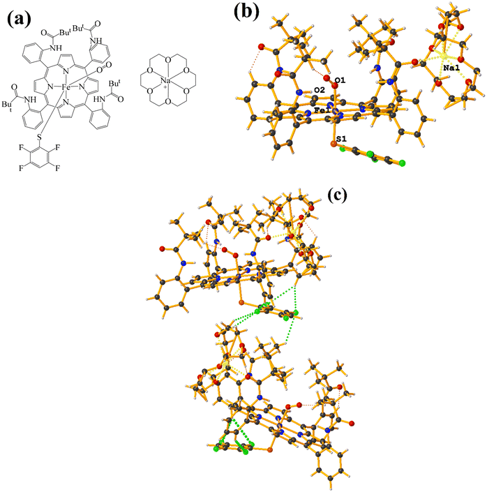 | ||
| Fig. 19 (a) Schematization of the molecular structure GAHLOQ. (b) Molecular structure of GAHLOQ. For clarity, the numbering of the atoms is not shown. (c) Supramolecular array of GAHLOQ. | ||
Again, as in GAHLIK, the amide groups help stabilize the Fe-bound dioxygen molecule. On the other hand, the fluorinated thiolate does not form stacking since it establishes interactions with the cation [Na⊂18C6] of the C–H⋯F–C type.
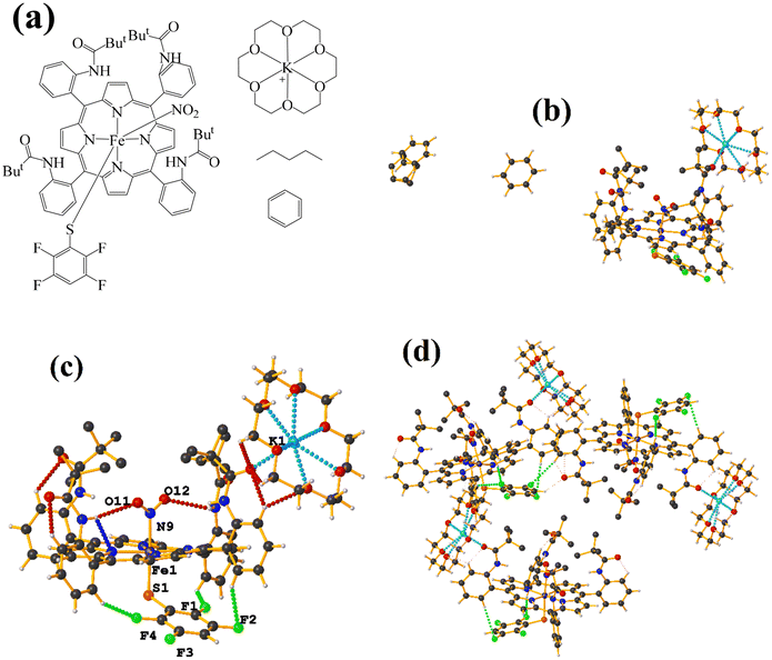 | ||
| Fig. 20 (a) Schematization of the molecular structure KULWOD. (b and c) Molecular structure of KULWOD. (d) Supramolecular array of KULWOD. For clarity, benzene and n-pentane are not shown. | ||
In this case the amide functional groups establish N–H⋯O–N interactions and on the other side of the TPP− ligand face, the thiolate exhibits C–H⋯F–C interactions, preventing stacking.
Ir metal complexes
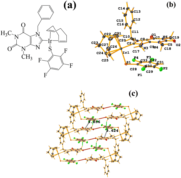 | ||
| Fig. 21 (a) Schematization of the molecular structure LULJOU. (b) Molecular structure of LULJOU. (c) Supramolecular array of LULJOU. | ||
The supramolecular arrangement shows a 2D array stabilized mainly by π–πF stacking and C–H⋯F–C and C–H⋯O![[double bond, length as m-dash]](https://www.rsc.org/images/entities/char_e001.gif) C hydrogen bonds. The stacking was established between the fluorinated ring of the thiolate and the six-membered ring of the theophylline C24–C29⋯N3/N4/C2–C5 [−1 + X, Y, Z, 3.856(3) Å; 3.4334(17) Å; 2.096 Å; and 6.0(2)°] and C24–C29⋯N3/N4/C2–C5 [X, Y, Z, 3.624(3) Å; 3.3797(17) Å; 1.444 Å; and 6.0(2)°]. Stacking π–πF was favored since Janiak has mentioned that the stability order should be considered as follows: πpoor–πpoor > πpoor–πrich > πrich–πrich.38 In this case, hierarchical stacking occurred between the two most electronically deficient rings.
C hydrogen bonds. The stacking was established between the fluorinated ring of the thiolate and the six-membered ring of the theophylline C24–C29⋯N3/N4/C2–C5 [−1 + X, Y, Z, 3.856(3) Å; 3.4334(17) Å; 2.096 Å; and 6.0(2)°] and C24–C29⋯N3/N4/C2–C5 [X, Y, Z, 3.624(3) Å; 3.3797(17) Å; 1.444 Å; and 6.0(2)°]. Stacking π–πF was favored since Janiak has mentioned that the stability order should be considered as follows: πpoor–πpoor > πpoor–πrich > πrich–πrich.38 In this case, hierarchical stacking occurred between the two most electronically deficient rings.
Ni metal complexes
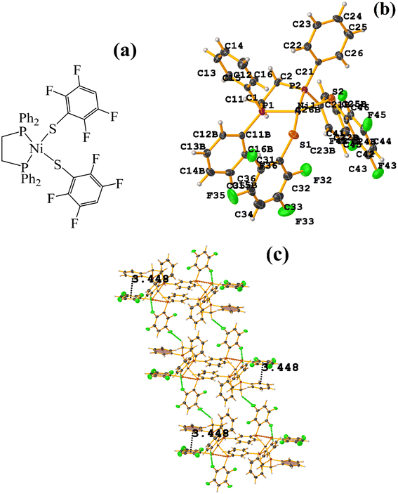 | ||
| Fig. 22 (a) Schematization of the molecular structure WUNQUR. (b) Molecular structure of WUNQUR. (c) Supramolecular array of WUNQUR. | ||
In the supramolecular structure there is intra π–πF stacking C9–C14⋯C27–C32 [X, Y, Z, 3.448(3) Å; 3.367(2) Å; 1.072 Å; and 7.1(3)°]. The 1D arrangement is not due to this interaction but to the C–F⋯H–C and S⋯S contacts.
Os metal complexes
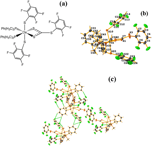
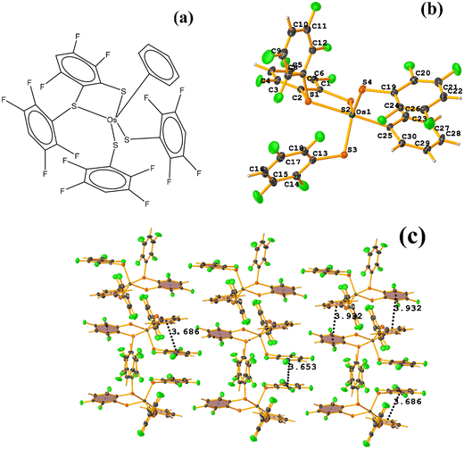 | ||
| Fig. 24 (a) Schematization of the molecular structure ECERIP. (b) Molecular structure of ECERIP. (c) Supramolecular array of ECERIP. | ||
This structure exhibited several types of stacking: π–πF and πF–πF. With the expected πF–πF interaction found on C19–C24⋯C19–C24 [1 − X, Y, 3/2 − Z, 3.654(4) Å; 3.348(3) Å; 1.463 Å; and 2.7 (3)°]. Stacking was also observed between a ring of one tetrafluorinated thiolate and the phenyl that is attached to Os: C19–C24⋯C25–C30 [X, Y, Z, 3.686(4) Å; 3.418(3) Å; not found; and 23.1(3)°]. A π–πF interaction was also found between the ring of the trifluorinated fragment that forms the metallacycle (SC6F3H-4) with the phenyl that is bonded to Os: C1–C6⋯C25–C30 [1 − X, 1 − Y, 1 − Z, 3.932(4) Å; 3.702(2) Å; 1.673 Å; and 19.0 (3)°]. All rings participating in the observed stackings must be energetically similar.
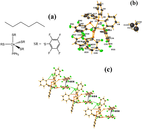 | ||
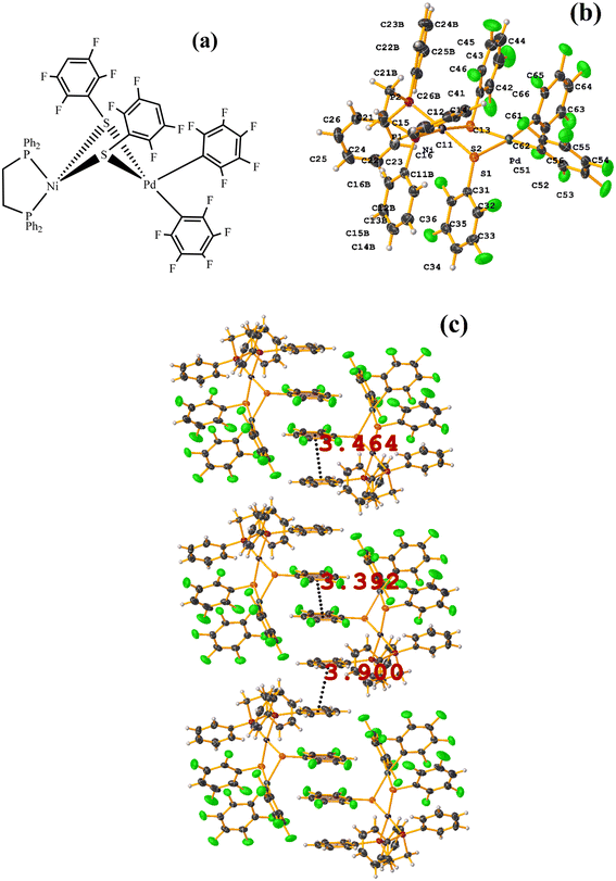
| Fig. 26 (a) Schematization of the molecular structure GENWOM. (b) Molecular structure of GENWOM. (c) Supramolecular array of GENWOM. | ||
In the packaging, the πF–πF stacking indicated by Conquest is observed, which is intramolecular C19–C24⋯C37–C42 [X, Y, Z, 3.464(6) Å; 3.415(4) Å; 1.318 Å; and 13.0(5)°]. And, a 1D network assisted by C–H⋯F–C and C–H⋯S interactions is observed.
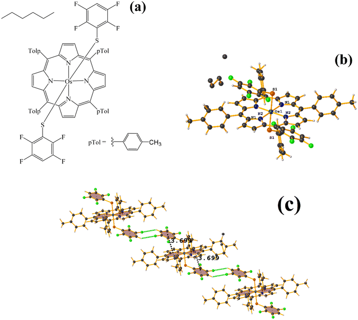 | ||
| Fig. 27 (a) Schematization of the molecular structure HANGEI. (b) Molecular structure of HANGEI. (c) Supramolecular array of HANGEI. | ||
As seen in Fig. 27, the interaction (πF–π, 3.699 Å) indicated by Conquest is established internally. However, the tetrafluorinated thiolate rings do not exhibit any πF–πF stacking, and instead, 1D networks are formed due to the centrosymmetric C–F⋯H–C interaction, R22(8).70,71
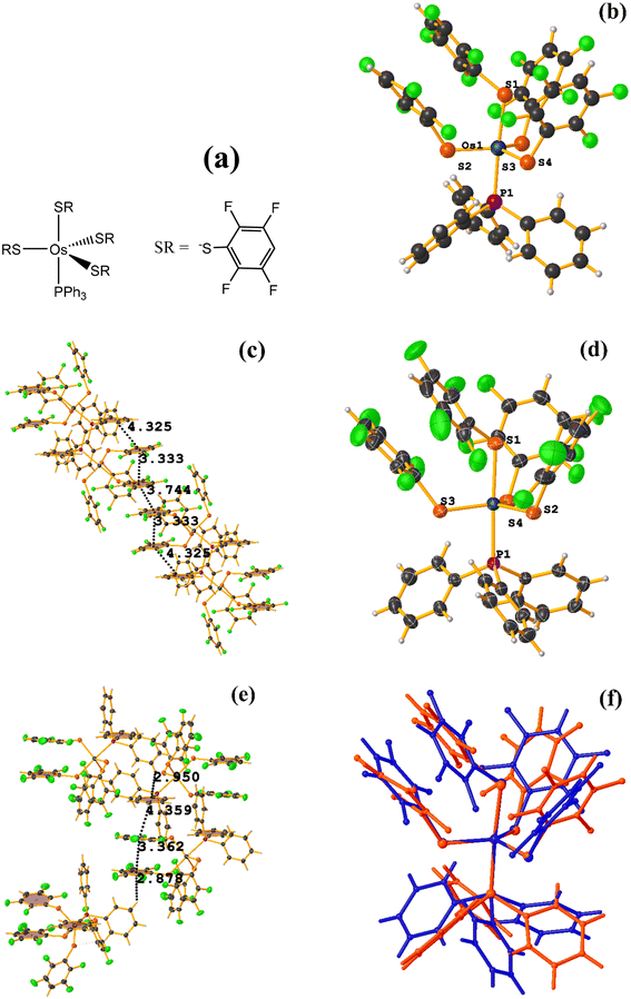
![[1 with combining macron]](https://www.rsc.org/images/entities/char_0031_0304.gif) space group, Fig. 28.72 However, years later, Zeleny et al. reported obtaining a polymorph of this structure, which is monoclinic P21/c (HENXIH01).73 From the point of view of the molecular structure, there are differences in the conformations adopted by the polymorphs, mainly with aromatic rings (either thiolates or phosphine) that affect the establishment of stacking, Fig. 28f.
space group, Fig. 28.72 However, years later, Zeleny et al. reported obtaining a polymorph of this structure, which is monoclinic P21/c (HENXIH01).73 From the point of view of the molecular structure, there are differences in the conformations adopted by the polymorphs, mainly with aromatic rings (either thiolates or phosphine) that affect the establishment of stacking, Fig. 28f.
Analyzing the supramolecular arrangement of HENXIH, it is observed that different type stackings (πF–πF intra and intermolecular) were formed. Regarding the intramolecular πF–πF interaction, the following parameters were found: C19–C24⋯C19–C24: [−X, −Y, −Z, 3.75(2) Å; 1.955 Å; and 0°]. On the other hand, the inter πF–πF stacking showed the following values: C19–C24⋯C25–C30: [X, Y, Z, 3.334(16) Å; 3.185(13) Å; 0.981 Å; and 8°]. There is another inter πF–π stacking, but according to the parameters, these are outside the cut-off to consider it a genuine interaction. This was established between a phosphine ring and another fluorinated thiolate ring: C1–C6–C25–C30: [−X, 1 − Y, 1 − Z, 4.325(14) Å; 3.586(11) Å; 2.897 Å; and 9°].
In the case of the other polymorph HENXIH01, only the intra πF–πF stacking was observed, with the following parameters: C19–C24⋯C31–C36: [X, Y, Z, 3.363(6) Å; 3.172(4) Å; 0.663 Å; and 11.3(5)°]. Additionally, another πF–π interaction was found, which is outside the cut-off parameters: C1–C6⋯C31–C36: [−X, 1 − Y, 1 − Z, 4.359(5) Å; 3.577(3) Å; 3.101 Å; and 10.5(4)°]. It is highlighted that instead of finding several stacking as was the case in HENXIH, the formation of T-shaped interactions (Fig. 4), C–H⋯π were identified: C9–H7⋯C19–C24 [X, 3/2 − Y, −1/2 + Z, 2.88 Å and 140°], C11–H9⋯C1–C6 and [1 − X, 1 − Y, 1 − Z, 2.95 Å and 147°]. This indicates that the different conformations adopted by the polymorphs affect in such a way that the arrangement of the rings is parallel on the same axis so that stacking is established, but in the other polymorph, this array is lost, and the interaction T-shaped is favored.
 | ||
| Fig. 29 (a) Schematization of the molecular structure OQEHUO. (b) Molecular structure of OQEHUO. (c) Supramolecular array of OQEHUO. | ||
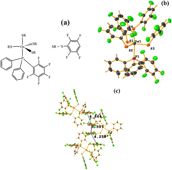
When analyzing the structure supramolecularly, the stacking indicated by Conquest was observed: C13–C18⋯C19–C24: [X, Y, Z, 3.537(5) Å; 3.350(4) Å; 1.456 Å; and 13.4(4)°]. This πF–πF interaction is established intramolecularly between two fluorinated benzene-thiolate rings. Additionally, two other πF–πF interactions were found that cannot be considered stackings since they are outside the established parameters. The first is established between the pentafluorinated ring of phosphine and a tetrafluorinated ring of a thiolate: C25–C30⋯C19–C24: [X, 1/2 − Y, −1/2 + Z, 4.663(5); 3.607(3) Å; 3.570 Å; and 11.9(4)°]. Interestingly, although it is not considered a true stacking, this interaction was formed between a pentafluorinated⋯tetrafluorinated ring. In the case of the other interaction, it occurred intermolecularly between two fluorinated rings of two thiolates: C1–C6⋯C13–C18: [2 − X, −1/2 + Y, 3/2 − Z, 4.250(6) Å; 3.553(4) Å; 2.553 Å; and 5.0(4)°].
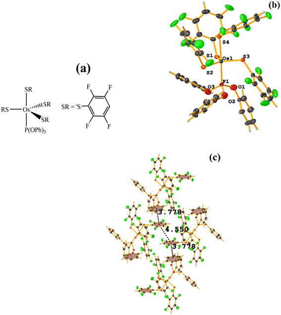
 | ||
| Fig. 31 (a) Schematization of the molecular structure ZAWWAV. (b) Molecular structure of ZAWWAV. (c) Supramolecular array of ZAWWAV. | ||
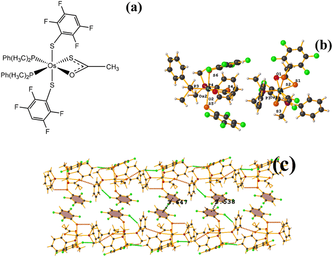
The first one found was: C3–C8⋯C3–C8: [1 − X, 1 − Y, 2 − Z, 3.647(4) Å; 3.323(2) Å; 1.502 Å; and 0.0(3)°]. However, Conquest does not indicate its presence within the analysis. The second exhibited the following parameters: C39–C44⋯C39–C44: [1 − X, 1 − Y, 1 − Z, 3.538(4) Å; 3.344(3) Å; 1.154 Å; and 0.0(3)°]. When comparing ERUHII [Os(III)(SR)2(S2CSR)(PMe2Ph)2] (R: 2,3,5,6-SC6F4H)67 with ZAWWAV, it is observed that the two compounds are very similar structurally speaking, except by the thiocarboxylate and carboxylate ligands. One has a terminal –CH3 (ZAWWAV), and the other a fluorinated thiolate (2,3,5,6-SC6F4H) (ERUHII). This change may affect whether the πF–πF interactions are established in this case. In the case of ERUHII, the πF–πF interactions were not established; otherwise, these stackings were observed with ZAWWAV. We do not have a clear explanation as to why this situation occurred.
![[1 with combining macron]](https://www.rsc.org/images/entities/char_0031_0304.gif) polymorph presented a large amount of intra and inter stacking πF–πF, and in the case of the other these were more limited in number. It is highlighted that the πF–πF interactions observed in the polymorph P
polymorph presented a large amount of intra and inter stacking πF–πF, and in the case of the other these were more limited in number. It is highlighted that the πF–πF interactions observed in the polymorph P![[1 with combining macron]](https://www.rsc.org/images/entities/char_0031_0304.gif) , were transformed into a T-shaped conformation on the other. In the case of ERUHII and ZAWWAV both complexes are structurally similar. But the changes mainly in the thiocarboxylate and carboxylate ligands (one has a –CH3 terminal (ZAWWAV), and the other a fluorinated thiolate (2,3,5,6-SC6F4H)) influence such that the first presents stacking and in the other no. In the other cases, according to Conquest, the structures exhibited stacking. However, the πF–πF was not found when performing the analysis, and T-shape and C–F⋯H–C interactions, among others, were observed.
, were transformed into a T-shaped conformation on the other. In the case of ERUHII and ZAWWAV both complexes are structurally similar. But the changes mainly in the thiocarboxylate and carboxylate ligands (one has a –CH3 terminal (ZAWWAV), and the other a fluorinated thiolate (2,3,5,6-SC6F4H)) influence such that the first presents stacking and in the other no. In the other cases, according to Conquest, the structures exhibited stacking. However, the πF–πF was not found when performing the analysis, and T-shape and C–F⋯H–C interactions, among others, were observed.
Pb metal complexes
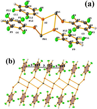
Reviewing the structure, we found two types of πF–πF stackings. Notably, one was not detected through Conquest. The first presented the following parameters: C1–C6⋯C7–C12: [−X, 2 − Y, 1 − Z, 3.589(3) Å; 3.341(2) Å; 1.374 Å; and 1.5(3)°]. And the other stacking presents values of: C1–C6⋯C7–C12: [1 − X, 2 − Y, 1 − Z, 3.526(3) Å; 3.343(2) Å; 1.167 Å; and 1.5(3)°]. In this way, πF–πF stackings are established, but the Pb–S coordination bond imposes them. It should also be noted in CANVUL.
Pd metal complexes
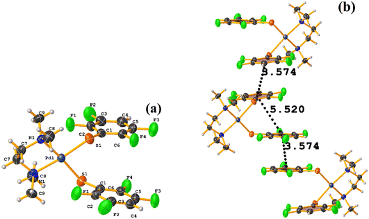
The stacking pointed out by Conquest was found: C1–C6⋯C1–C6: [1/2 − X, −1/2 − Y, 3/2 − Z, 3.5743(14) Å; 3.3932(9) Å; 1.123 Å; and 0.02(11)°]. It is highlighted that this interaction is established intermolecularly. On the other hand, the intramolecular interaction is outside the limits to be considered stacking: C1–C6⋯C1–C6: [1/2 − X, Y, 2 − Z, 5.5200(15) Å; 3.1945(9) Å; 4.502 Å; and 7.05(11)°].
Noteworthy is the fact that the complex's cis arrangement facilitates stacking. Still, it is interesting that the intermolecular and not the intramolecular πF–πF interaction was formed.
 | ||
| Fig. 34 (a) Schematization of the molecular structure of HIHROH. (b) Molecular structure of HIHROH. (c) Supramolecular array of HIHROH. The dication was removed for more clarity. | ||
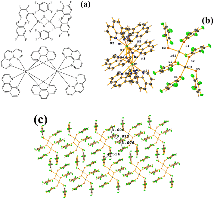
In addition, another πF–πF stacking was found that is outside the limits of the geometric parameters: C31–C36⋯C31–C36: [−X, 1 − Y, 1 − Z, 4.514(9) Å; 3.250(6) Å; 3.133 Å; and 0.0(8)°]. Interestingly, in this system, it can be observed that despite the presence of the phen ligands, these do not affect the stacking of the thiolates even when the former has a larger π surface.53,54,78
 | ||
| Fig. 36 (a) Molecular structure of HIHSAU. (b) Supramolecular array of HIHSAU. (c) Overlay of HIHSAU (blue) and MIXFAB (red) structures. | ||
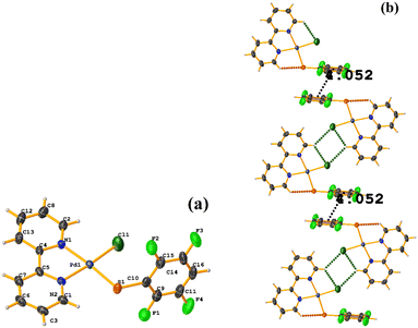
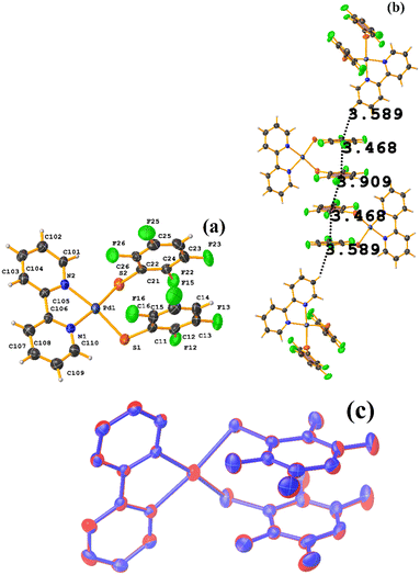
Comparing the supramolecular arrangement with MIXFAB ([Pt(II)(2,3,4,6-SC6F4-4-H)2(2,2′-bipy)]) that we have reported, it is observed that it is isomorphic, Fig. 6b.51 It is important to highlight what Aakeröy et al. pointed out: “the probability that a certain motif will appear in a crystalline lattice is, in many ways, a measure of the yield of a supramolecular reaction”.79 It can be noted that both tectons (HIHSAU and MIXFAB) present the same point group and are structurally similar, Fig. 36c; this implies that there is reproducibility in the expected motifs (πF–πF stackings), and for this reason, the supramolecular arrangements are isomorphic. This connectivity indicates the robustness of this interaction in this type of tecton, showing efficient supramolecular yielding.
Pt metal complexes
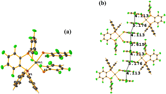
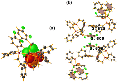
The intermolecular πF–πF stacking indicated by Conquest was found: C31–C36⋯C31–C36: [−X, 1 − Y, −Z, 3.616(7) Å; 3.418(5) Å; 1.178 Å; and 0.0(6)°]. Another πF–πF stacking was found when analyzing the structure by Olex 2, but the parameters were out of limits: C25–C30⋯C25–C30: [−X, 1 − Y, 1 − Z, 5.176(5) Å; 3.431(4) Å; 3.877 Å; and 0.0(4)°]. The other intra πF–πF stacking shown in Fig. 38 is also outside the limits to be considered a genuine interaction: C25–C30⋯C31–C36: [X, Y, Z, 4.113(8) Å; 0.371(5) Å; 2.690 Å; and 6.2(5)°].
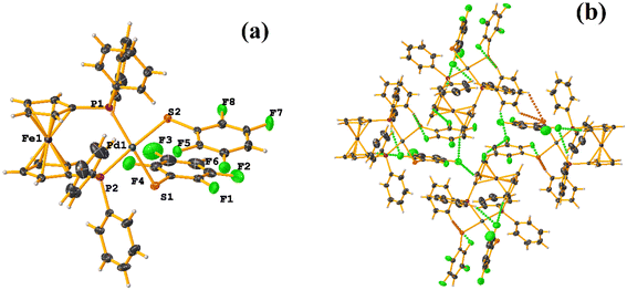
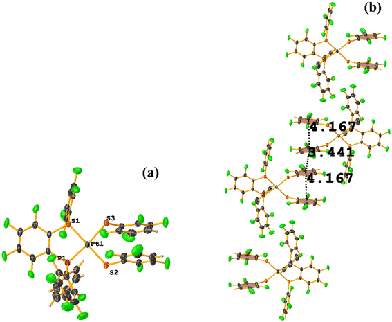
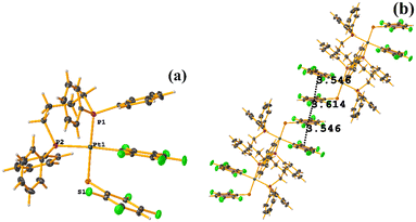
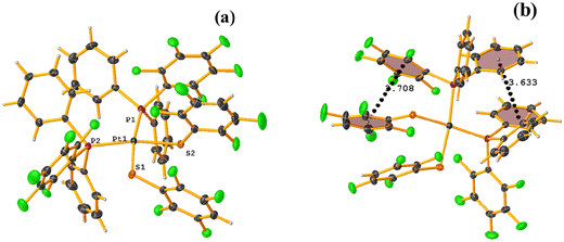
Two types of πF–πF stacking were found: C31–C36⋯C31–C36: (intermolecular stacking) [2 − X, 1 − Y, −Z, 3.441(4) Å; 3.349(3) Å; 0.778 Å; and 0.0(4)°] and, intramolecular stacking C25–C30⋯C31–C36: [X, Y, Z, 4.167(5) Å; 3.307(3) Å; 2.581 Å; and 6.5(4)°]. Structurally, BIGXOF and BIGXUL are similar. However, the supramolecular arrangement presents differences. The first forms an infinite column of πF–πF stackings, although of all of these, only one can be consider a stacking interaction that meets the geometric parameters (Cg⋯Cg: 3.616(7) Å). In the case of BIGXUL, this infinite πF–πF stacking is not observed since the appearance of C–F⋯π interactions stops it. This being due to the presence of the phenyl ring (pentafluorinated) of phosphine, which is present in BIGXUL and not in BIGXOF.
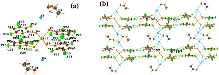
The πF–πF intramolecular stacking indicated by Conquest was found: C1–C6⋯C7–C12: [2 − X, 2 − Y, 2 − Z, 3.586(3) Å; 3.539(2) Å; 1.344 Å; and 12.6(3)°]. In the supramolecular arrangement, a 2D array is observed; however, this is not due to the stacking. The arrangement is layered; in one, the potassium cations are accommodated with the EtOH solvates; and in the other, the anion [Pt(II)(2,3,4,6-SC6F4-4-H)4]2−. It should be noted that the ion–ion interaction (between K+ cation and complex anion) prevails and is more dominant than the πF–πF stacking. This is mentioned because the latter could have persisted, but because the former is energetically stronger (ion–ion (100–350 kJ mol−1)83vs. stacking (0–10 kJ mol−1)34), this did not happen. Comparing LOKVUD ([Et4N][Au(2,3,4,6-SC6F4-4-H)4]·EtOH, Fig. 11d) with this structure, it is observed that both exhibit a square plane geometry around the metal center. However, in the first structure, the πF–πF stackings were fully established; in this case, the cation Et4N+ does not interrupt these interactions as it happens in the case of the K+ cation that disrupts them.
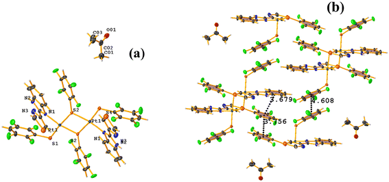
![[double bond, length as m-dash]](https://www.rsc.org/images/entities/char_e001.gif) O (TBZ = 4-(1H-benzimidazol-2-yl)-1,3-thiazole), Fig. 42.84 Reviewing the supramolecular arrangement, the stackings indicated by Conquest were found, and those of interest πF–πF showed the following parameter values: both are intermolecular C20–C25⋯C20–C25 [3 − X, 2 − Y, 1 − Z, 3.756(4) Å; 3.363(2) Å; 1.673 Å; and 0.0(3)°] and C14–C19⋯C14–C19 [2 − X, 2 − Y, 2 − Z, 4.608(5) Å; 3.373(3) Å; 3.139 Å; and 0.0(4)°]. The second interaction is off-limits and should not be considered genuine stacking. A third intra-stacking of the type πF–πF was established between the tetrafluorinated thiolate and the six-membered ring of the benzimidazole fragment having the following parameters: C4–C9⋯C20–C25 [2 − X, 2 − Y, 1 − Z, 3.679(4) Å; 3.465(3) Å; 0.475 Å; and 12.5(3)°].
O (TBZ = 4-(1H-benzimidazol-2-yl)-1,3-thiazole), Fig. 42.84 Reviewing the supramolecular arrangement, the stackings indicated by Conquest were found, and those of interest πF–πF showed the following parameter values: both are intermolecular C20–C25⋯C20–C25 [3 − X, 2 − Y, 1 − Z, 3.756(4) Å; 3.363(2) Å; 1.673 Å; and 0.0(3)°] and C14–C19⋯C14–C19 [2 − X, 2 − Y, 2 − Z, 4.608(5) Å; 3.373(3) Å; 3.139 Å; and 0.0(4)°]. The second interaction is off-limits and should not be considered genuine stacking. A third intra-stacking of the type πF–πF was established between the tetrafluorinated thiolate and the six-membered ring of the benzimidazole fragment having the following parameters: C4–C9⋯C20–C25 [2 − X, 2 − Y, 1 − Z, 3.679(4) Å; 3.465(3) Å; 0.475 Å; and 12.5(3)°].
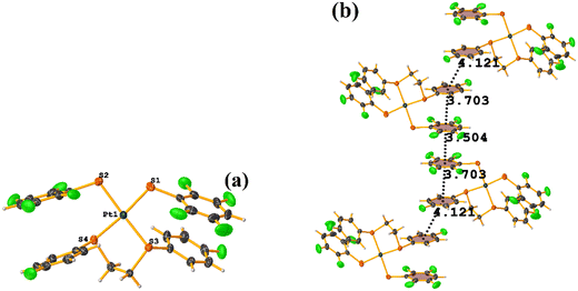
First, we find the πF–πF stacking indicated by Conquest, which is intermolecular: C7–C12⋯C7–C12 [2 − X, 2 − Y, 2 − Z, 3.504(7) Å; 3.326(5) Å; 1.101 Å; and 0.0(6)°]. In addition, another πF–πF stacking was found between the tetrafluorinated thiolate and the monofluorinated thiolate, which is intramolecular: C7–C12⋯C19–C24 [X, Y, Z, 3.704(7) Å; 3.332(5) Å; 1.489 Å; and 6.2(6)°]. Interestingly, it is not expected to observe monofluorinated thiolate rings participating in stacking interactions. We consider that this happened due to the order of stability indicated by Janiak (πpoor–πpoor > πpoor–πrich > πrich–πrich). This could be established since the molecule has only two types of aromatic rings. For example, the intermolecular πF–πF stacking interaction was found between the two monofluorinated thiolate rings, and their geometric parameters were too far outside the limits to be considered genuine stacking: C19–C24⋯C19–C24 [1 − X, 3 − Y, 2 − Z, 4.119(7) Å; 2.379 Å; and 0.0(6)°]. These values indicate that there is some repulsion between the rings.
Rh metal complexes
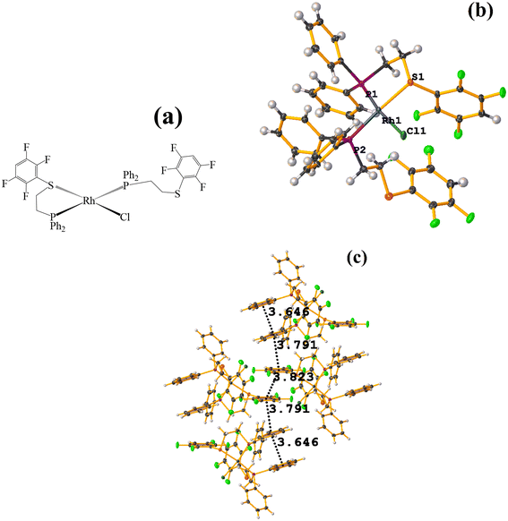 | ||
| Fig. 48 (a) Schematization of the molecular structure of NADSUI. (b) Molecular structure of HIHROH. (c) Supramolecular array of NADSUI. | ||
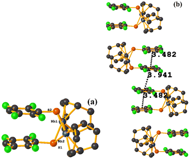
The intermolecular πF–πF stacking was found where the fluorinated thiolate rings participated: C3–C8⋯C3–C8 [1 − X, −Y, 1 − Z, 3.8230(8) Å; 3.2912(6) Å; 1.945 Å; and 0.04(7)°]. In addition, other intra- and intermolecular stackings of the type πF–π and π–π were found: C3–C8⋯C15–C20 [1 − X, 1 − Y, 1 − Z, 3.7912(9) Å; 3.7235(6) Å; 0.700 Å; and 18.70(7)°] and C15–C20⋯C29–C34 [X, Y, Z, 3.6461(9) Å; 3.6160(6) Å; 1.411 Å; and 15.84(7)°].
Ru metal complexes
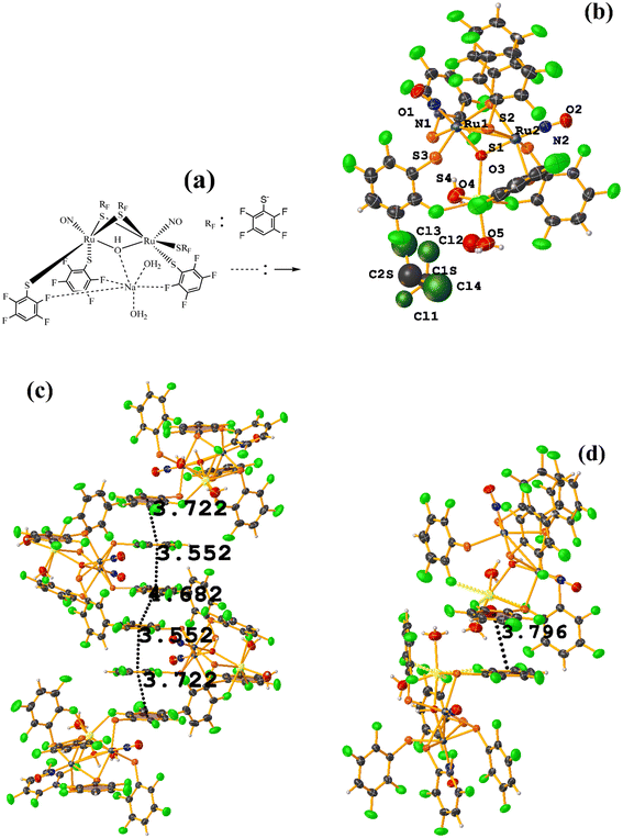 | ||
| Fig. 49 (a) Schematization of the molecular structure of IQIDOD. (b) Molecular structure of IQIDOD. (c and d) Supramolecular arrays of IQIDOD. | ||
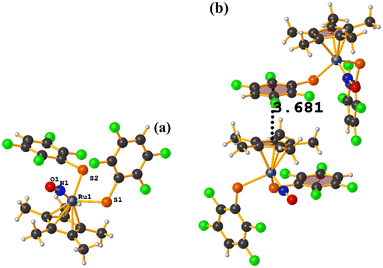
In addition, intramolecular πF–πF stacking was found: C1–C6⋯C1–C6 [X, Y, Z, 3.552(2) Å; 3.1422(15) Å; 1.275 Å; and 7.40(17)°]. Another intermolecular πF–πF stacking (Cg⋯Cg: 4.682 Å) was also found, but the parameters are outside the limits to consider this interaction genuine.
On the other hand, the greater molecular complexity observed in IQIDOD in the first instance led us to think that stacking would not be established, and in this case, it was quite the opposite. In this situation, although in the first instance, the tecton is appropriately selected (geometry and ligands involved), and it is ensured that there are no competitive interactions that prevent stacking, other contributions affect this. For this reason, stacking is not a predictable interaction from the point of view of crystal engineering.
Sn metal complexes
Miscellaneous
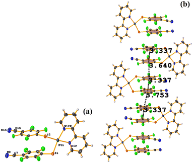
Comparing this structure with the one we have published MIXFAB ([Pt(II)(2,2′-bpy)(2,3,4,6-SC6F4-4-H)2]), in our structure, we do not observe the formation of infinite columns dictated by the πF–πF stackings, see this in section 4.51 This is due to the electron-attracting effect of the –CN group on the tetrafluorinated thiolate ring. This can decrease the repulsion between the rings, making them electron-deficient aromatic rings and promoting πF–πF stacking. In the case of the MIXFAB tecton, the H atom in position 4 within the ring does not promote this as efficiently, so we do not see the formation of infinite columns. In this way, we believe that the thiolate 2,3,4,6-SC6F4-4-CN should be exploited in other coordination and organometallic compounds to observe if πF–πF stacking can be favored more efficiently.
7. Conclusions
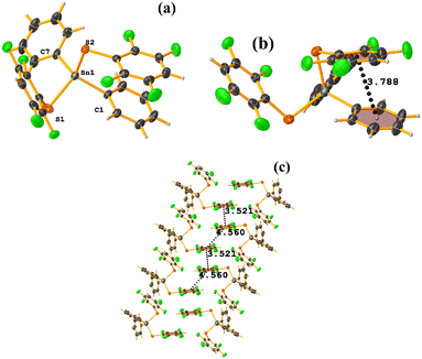
Throughout this analysis employing Conquest, specific points must be considered to answer the question initially asked: How reliable and predictable is the fluorinated thiolate 2,3,5,6-SC6F4-H-4 in establishing πF–πF stacking in metal complexes from crystal engineering's point of view?1. First, the type of tecton used to form the supramolecular arrangements must be considered through this interaction. From this, we can point out that tectons with Dh4 or Th symmetry or within the subgroups of these point groups established the πF–πF stacking more efficiently.95 This was corroborated with complexes with square planar or tetrahedral geometry. For instance, [Et4N][Au(2,3,5,6-SC6F4-H-4)4]·EtOH (LOKVUD), [SnPh2(2,3,4,6-SC6F4-4-H)2] (PIDMOF), and [Pt(2,2′-bpy)(2,3,4,6-SC6F4-4-CN)2] (EMEGAE). Special mention should be made to complexes belonging to C2h point groups since in the case of [Et4N][Au(2,3,5,6-SC6F4-H-4)2] (LOKWEO), 1D arrangements were formed through πF–πF stacking. Although it was the only structure detected by Conquest that presented this specific point group, the stacking was carried out efficiently. On the other hand, in the case of specific Oh or D3h point groups or subgroups of these, there were a few cases in which πF–πF stacking was established as a reliable synthon. For instance, in the case of complex [Os(IV)(2,3,5,6-SC6F4H-4)2(SC6F3H-4(2,3,5,6-SC6F4H)-2)(C6H5)] (ECERIP, trigonal bipyramidal geometry) presented an arrangement of 2D packing. However, this was not precisely dictated by πF–πF stacking but by various stacking (πF–π) involving fluorinated and non-fluorinated rings. Also, in the case of complexes with octahedral geometry, a few examples presented a packing dictated by stacking, [Os(III)(2,3,5,6-SC6F4-H-4)2(SOC-CH3)(P(CH3)2Ph)2] (ZAWWAV), [Na⊂222][Co(III)(2,3,5,6-SC6F4-H-4)2(TPP)]·C6H5Cl (COSJOJ) and [Na⊂222][Co(III)(2,3,5,6-SC6F4-H-4)(TPP)] (COSJUP). From this, we can indicate that the selection of the point group of the tecton is crucial. In addition, the effect of coordinated ligands must be considered since this can modify the point group and decrease its symmetry, which affects stacking, because depending on the nature of the ligand, it can create molecular crowding or a hindering steric effect limiting the interaction.
2. Attention should be paid to ligands other than coordinated tetrafluorinated thiolates since, as observed in the structures, FOLWIM, FOLWOS, DIDCEY, GAHLIK, GAHLOQ, KUDWOD, the first two complexes of Co, and the last of Fe, not only the steric hindrance shown by the TPP− ligand avoid the formation of the stackings, but also the presence of heteroatoms (N, O) can cause the formation of hydrogen bonds and prevent this interaction.
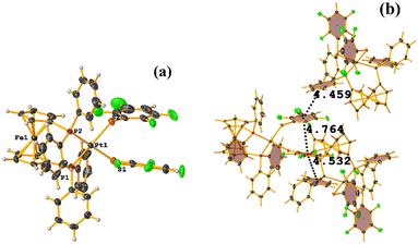
3. It should be avoided the use of ligands with a large π surface area, i.e., containing the 1,10-phen ligand (HIHROH, Pd complex, and LUQMOC Pt complex) or those coordinated to ferrocenyl-derived ligands (FORMUW or BOQHOG) since they prevent stacking. However, it should be emphasized that in the case of tectons with the 1,10-phen ligand, the πF–πF stackings prevailed despite these ligands with a larger π surface area being present. Contrary to what was observed with ferrocenyl-derived ligands.
4. It is fundamental to observe the nature of the tecton, whether it is neutral or ionic. In the case of being ionic, select the nature of the participating cations or anions. This is mentioned for the specific case of K2[Pt(II)(2,3,5,6-SC6F4-H-4)4]·EtOH (BOQHOG), most likely the ion–ion interaction (between K+ and the anion complex) limited the stacking. In this way, the establishment of stacking can be affected when it competes with an energetically stronger interaction.
5. It is important to emphasize what was observed in the structures of HIHSAU and MIXFAB (see the section on Pd complexes), which presented the term used by Aakeröy: supramolecular yielding.
Furthermore, it must be mentioned that other issues should be considered in addition to these recommendations regarding the type of tecton to use.
1. Stacking can be affected by polymorphism. This is observed for both Os complexes HENXIH and HENXIH01. Where small differences, mainly conformational, in the spatial arrangement of the rings (mainly the tetrafluorinated thiolates) affect the amount of intra- and intermolecular stacking.
These suggestions should be considered in the design of the tecton to ensure πF–πF stacking. However, this interaction is susceptible to formation if it competes with energetically stronger interactions or from other factors discussed in this perspective. And hence unfortunately, no definitive answer can be given, at this point, as to how feasible and reliable this interaction can be exploited from a crystal engineering point of view. Nonetheless, considering the above points, researchers can largely guarantee that πF–πF stacking would prevail in molecular packing and that it can be exploited as a crystal engineering tool.
Additionally, we encourage exploring the ability of the ligand 2,3,4,6-SC6F4-4-CN since, as indicated in the miscellaneous section, it may be a more suitable ligand to form the stacking instead of 2,3,5,6-SC6F4-H-4.
Data availability
The data supporting this article has been included as part of the ESI.†Conflicts of interest
The authors declare that they have no known competing financial interests or personal relationships that could have appeared to influence the work reported in this paper.Acknowledgements
J. M. G.-A. would like to thank PAPIIT-DGAPA-UNAM for the financial support granted through project IT200523. J. M. G.-A. also thanks CONAHCYT for funding project CBF2023-2024-1325 through the Ciencia Básica y de Frontera 2023–2024 call. D. M.-M. gratefully thanks the generous financial support of DGAPA-UNAM PAPIIT IN223323 and CONAHCYT A1-S-033933.References
- J. W. Steed and J. L. Atwood, Supramolecular Chemistry, Wiley, 2009 Search PubMed.
- D. Braga, Chem. Commun., 2003, 3, 2751–2754 RSC.
- G. R. Desiraju, Crystal Engineering: The Design of Organic Solids, Elsevier, Amsterdam, 1989 Search PubMed.
- E. R. T. Tiekink, J. Vittal and M. Zaworotko, Organic Crystal Engineering: Frontiers in Crystal Engineering, John Wiley & Sons, 2010 Search PubMed.
- K. Geng, T. He, R. Liu, S. Dalapati, K. T. Tan, Z. Li, S. Tao, Y. Gong, Q. Jiang and D. Jiang, Chem. Rev., 2020, 120, 8814–8933 CrossRef CAS PubMed.
- L. Brammer, Chem. Soc. Rev., 2004, 33, 476–489 RSC.
- C. B. Aakeröy and A. M. Beatty, Aust. J. Chem., 2001, 54, 409–421 CrossRef.
- D. Braga, J. Chem. Soc., Dalton Trans., 2000, 3705–3713 RSC.
- D. Braga and F. Grepioni, Chem. Commun., 2005, 3635–3645 RSC.
- T. R. Cook and P. J. Stang, Chem. Rev., 2015, 115, 7001–7045 CrossRef CAS PubMed.
- R. Chakrabarty, P. S. Mukherjee and P. J. Stang, Chem. Rev., 2011, 111, 6810–6918 CrossRef CAS PubMed.
- M. Fujita, M. Tominaga, A. Hori and B. Therrien, Acc. Chem. Res., 2005, 38, 369–378 CrossRef CAS PubMed.
- M. Kawano and M. Fujita, Coord. Chem. Rev., 2007, 251, 2592–2605 CrossRef CAS.
- M. J. Zaworotko, Cryst. Growth Des., 2007, 7, 4 CrossRef CAS.
- M. Safaei, M. M. Foroughi, N. Ebrahimpoor, S. Jahani, A. Omidi and M. Khatami, TrAC, Trends Anal. Chem., 2019, 118, 401–425 CrossRef CAS.
- L. Jiao, J. Y. R. Seow, W. S. Skinner, Z. U. Wang and H. L. Jiang, Mater. Today, 2019, 27, 43–68 CrossRef CAS.
- L. Brammer, J. C. Mareque Rivas, J. Reinaldo Atencio, S. Fang and F. Christopher Pigge, J. Chem. Soc., Dalton Trans., 2000, 3855–3867 RSC.
- G. A. Jeffrey, An introduction to hydrogen bonding, Oxford University Press, New York, 1997 Search PubMed.
- G. Desiraju and T. Steiner, in The Weak Hydrogen Bond: In Structural Chemistry and Biology, ed. I. U. of C. M. on Crystallography, Oxford University Press, 2001 Search PubMed.
- T. Steiner, Angew. Chem., Int. Ed., 2002, 41, 48–76 CrossRef CAS.
- L. Brammer, in Crystal Design: Structure and Function, ed. G. R. Desiraju, John Wiley & Sons, Ltd., 2003, vol. 7, pp. 1–75 Search PubMed.
- L. J. Prins, D. N. Reinhoudt and P. Timmerman, Angew. Chem., Int. Ed., 2001, 40, 2382–2426 CrossRef CAS PubMed.
- M. Whitesides, E. E. Simanek, J. P. Mathias, C. T. Seto, D. Chin, M. Mammen and D. M. Gordon, Acc. Chem. Res., 1995, 28, 37–44 CrossRef.
- Self-Assembly in Supramolecular Systems, ed. J. F. Stoddart, L. F. Lindoy and I. M. Atkinson, The Royal Society of Chemistry, 2000 Search PubMed.
- F. H. Allen, W. D. Samuel Motherwell, P. R. Raithby, G. P. Shields and R. Taylor, New J. Chem., 1999, 23, 25–34 RSC.
- G. R. Desiraju, Angew. Chem., Int. Ed. Engl., 1995, 34, 2311–2327 CrossRef CAS.
- F. H. Allen, Acta Crystallogr., Sect. B: Struct. Sci., 2002, 58, 380–388 CrossRef PubMed.
- C. B. Aakeröy and D. J. Salmon, CrystEngComm, 2005, 7, 439–448 RSC.
- S. K. Burley and G. A. Petsko, Science, 1985, 229, 23–28 CrossRef CAS PubMed.
- J. Černý, M. Kabeláč and P. Hobza, J. Am. Chem. Soc., 2008, 130, 16055–16059 CrossRef PubMed.
- E. A. Meyer, R. K. Castellano and F. Diederich, Angew. Chem., Int. Ed., 2003, 42, 1210–1250 CrossRef CAS PubMed.
- W. R. Zhuang, Y. Wang, P. F. Cui, L. Xing, J. Lee, D. Kim, H. L. Jiang and Y. K. Oh, J. Controlled Release, 2019, 294, 311–326 CrossRef CAS PubMed.
- R. Thakuria, N. K. Nath and B. K. Saha, Cryst. Growth Des., 2019, 19, 523–528 CrossRef CAS.
- J. H. Deng, J. Luo, Y. L. Mao, S. Lai, Y. N. Gong, D. C. Zhong and T. B. Lu, Sci. Adv., 2020, 6, 1–9 Search PubMed.
- M. O. Sinnokrot and C. D. Sherrill, J. Phys. Chem. A, 2006, 110, 10656–10668 CrossRef CAS PubMed.
- C. A. Hunter and J. K. M. Sanders, J. Am. Chem. Soc., 1990, 112, 5525–5534 CrossRef CAS.
- M. O. Sinnokrot and C. D. Sherrill, J. Am. Chem. Soc., 2004, 126, 7690–7697 CrossRef CAS PubMed.
- C. Janiak, J. Chem. Soc., Dalton Trans., 2000, 3885–3896 RSC.
- Y. C. Chang, Y. Da Chen, C. H. Chen, Y. S. Wen, J. T. Lin, H. Y. Chen, M. Y. Kuo and I. Chao, J. Org. Chem., 2008, 73, 4608–4614 CrossRef CAS PubMed.
- O. V. Dolomanov, L. J. Bourhis, R. J. Gildea, J. A. K. Howard and H. Puschmann, J. Appl. Crystallogr., 2009, 42, 339–341 CrossRef CAS.
- A. L. Spek, Acta Crystallogr., Sect. D: Biol. Crystallogr., 2009, 65, 148–155 CrossRef CAS PubMed.
- J. C. Páez-Franco, M. R. Zermeño-Ortega, C. M. De O-Contreras, D. Canseco-González, J. R. Parra-Unda, A. Avila-Sorrosa, R. G. Enríquez, J. M. Germán-Acacio and D. Morales-Morales, Pharmaceutics, 2022, 14, 402 CrossRef PubMed.
- S. Mishra and S. Daniele, Chem. Rev., 2015, 115, 8379–8448 CrossRef CAS PubMed.
- R. Berger, G. Resnati, P. Metrangolo, E. Weber and J. Hulliger, Chem. Soc. Rev., 2011, 40, 3496–3508 RSC.
- P. Panini and D. Chopra, in Hydrogen Bonded Supramolecular Structures, 2015, vol. 87, pp. 37–67, lecture notes in chemistry Search PubMed.
- K. Reichenbächer, H. I. Süss and J. Hulliger, Chem. Soc. Rev., 2005, 34, 22–30 RSC.
- S. Bacchi, M. Benaglia, F. Cozzi, F. Demartin, G. Filippini and A. Gavezzotti, Chem. – Eur. J., 2006, 12, 3538–3546 CrossRef CAS PubMed.
- F. Cozzi, S. Bacchi, G. Filippini, T. Pilati and A. Gavezzotti, CrystEngComm, 2009, 11, 1122–1127 RSC.
- H. Juarez-Garrido, J. M. Germán-Acacio, E. Jaime-Adán, J. Barroso-Flores, V. Lara, R. Reyes-Martinez, R. A. Toscano, S. Hernández-Ortega and D. Morales-Morales, CrystEngComm, 2022, 24, 7932–7943 RSC.
- H. Torrens, Coord. Chem. Rev., 2000, 196, 331–352 CrossRef CAS.
- M. Corona-Rodriguez, S. Hernandez-Ortega, J. Valdes-Martinez and D. Morales-Morales, Supramol. Chem., 2007, 19, 579–585 CrossRef CAS.
- G. Backman-Blanco, H. Valdés, M. T. Ramírez-Apan, P. Cano-Sanchez, S. Hernandez-Ortega, A. L. Orjuela, J. Alí-Torres, A. Flores-Gaspar, R. Reyes-Martínez and D. Morales-Morales, J. Inorg. Biochem., 2020, 211, 111206 CrossRef CAS PubMed.
- Y.-M. Sun, F.-Y. Dong, D.-Q. Wang, Y.-L. Wang, Y.-T. Li and J.-M. Dou, J. Inorg. Organomet. Polym. Mater., 2010, 20, 168–176 CrossRef CAS.
- G. V. Janjić, P. V. Petrović, D. B. Ninković and S. D. Zarić, J. Mol. Model., 2011, 17, 2083–2092 CrossRef PubMed.
- S. Watase, T. Kitamura, N. Kanehisa, M. Nakamoto, Y. Kai and S. Yanagida, Acta Crystallogr., Sect. C: Cryst. Struct. Commun., 2004, 60, 104–106 CrossRef PubMed.
- G. Moreno-Alcántar, L. Turcio-García, J. M. Guevara-Vela, E. Romero-Montalvo, T. Rocha-Rinza, Á. M. Pendás, M. Flores-Álamo and H. Torrens, Inorg. Chem., 2020, 59, 8667–8677 CrossRef PubMed.
- G. Romo-Islas, G. Moreno-Alcántar, M. Flores-Álamo and H. Torrens, J. Fluor. Chem., 2020, 236, 109578 CrossRef CAS.
- G. Moreno-Alcántar, C. Díaz-Rosas, A. Fernández-Alarcón, L. Turcio-García, M. Flores-Álamo, T. Rocha-Rinza and H. Torrens, Inorganics, 2021, 9, 1–15 CrossRef.
- P. Doppelt, J. Fischer and R. Weiss, J. Am. Chem. Soc., 1984, 106, 5188–5193 CrossRef CAS.
- P. Doppelt, J. Fischer, L. Ricard and R. Weiss, New J. Chem., 1987, 11, 357–364 CAS.
- P. Doppelt, J. Fischer and R. Weiss, Croat. Chem. Acta, 1984, 57, 507–518 CAS.
- M. Schappacher, L. Ricard, J. Fischer, R. Weiss, E. Bill, R. Montiel-Montoya, H. Winkler and A. X. Trautwein, Eur. J. Biochem., 1987, 168, 419–429 CrossRef CAS PubMed.
- H. Nasri, K. J. Halier, Y. Wang, B. H. Huynh and W. R. Scheidt, Inorg. Chem., 1992, 31, 3459–3467 CrossRef CAS.
- I. Eslava-Gonzalez, H. Valdés, M. Teresa Ramírez-Apan, S. Hernandez-Ortega, M. Rosario Zermeño-Ortega, A. Avila-Sorrosa and D. Morales-Morales, Inorg. Chim. Acta, 2020, 507, 119588 CrossRef CAS.
- M. A. Usón and J. M. Llanos, J. Organomet. Chem., 2002, 663, 98–107 CrossRef.
- M. Cerón, L. Meléndez, S. Bernès, M. Arroyo and A. Ramírez-Monroy, J. Chem. Crystallogr., 2012, 42, 1119–1123 CrossRef.
- M. Arroyo, S. Bernes, J. Cerón, J. Rius and H. Torrens, Inorg. Chem., 2004, 43, 986–992 CrossRef CAS PubMed.
- M. Cerón, M. Arroyo and S. Bernès, Acta Crystallogr., Sect. E: Struct. Rep. Online, 2006, 62, 2167–2169 CrossRef.
- J. P. Collman, D. S. Bohle and A. K. Powell, Inorg. Chem., 1993, 32, 4004–4011 CrossRef CAS.
- M. C. Etter, J. C. MacDonald and J. Bernstein, Acta Crystallogr., Sect. B: Struct. Sci., 1990, 46, 256–262 CrossRef PubMed.
- J. Bernstein, R. E. Davis, L. Shimoni and N.-L. Chang, Angew. Chem., Int. Ed. Engl., 1995, 34, 1555–1573 CrossRef CAS.
- M. Arroyo, J. A. Chamizo, D. L. Hughes, R. L. Richards, P. Roman, P. Sosa and H. Torrens, J. Chem. Soc., Dalton Trans., 1994, 1819–1824 RSC.
- P. Zeleny, M. Arroyo, L. Meléndez and S. Bernès, IUCrData, 2019, 4, 2–13 CrossRef.
- M. Cerón, V. Cortina, A. Ramírez-Monroy, S. Bernès, H. Torrens and M. Arroyo, Polyhedron, 2011, 30, 1250–1257 CrossRef.
- R. Moreno-Esparza, H. Torrens, M. Arroyo, J. Briansó, C. Miravitlles and J. Rius, Polyhedron, 1995, 14, 1601–1606 CrossRef CAS.
- M. Basauri-Molina, S. Hernández-Ortega, R. A. Toscano, J. Valdés-Martínez and D. Morales-Morales, Inorg. Chim. Acta, 2010, 363, 1222–1229 CrossRef CAS.
- V. Lingen, A. Lüning, C. Strauß, I. Pantenburg, G. B. Deacon, A. Klein and G. Meyer, Eur. J. Inorg. Chem., 2013, 4450–4458 CrossRef CAS.
- S. Grimme, Angew. Chem., Int. Ed., 2008, 47, 3430–3434 CrossRef CAS PubMed.
- C. B. Aakeröy, A. M. Beatty and B. A. Helfrich, J. Am. Chem. Soc., 2002, 124, 14425–14432 CrossRef PubMed.
- C. Herrera-Álvarez, V. Gómez-Benítez, R. Redón, J. J. García, S. Hernández-Ortega, R. A. Toscano and D. Morales-Morales, J. Organomet. Chem., 2004, 689, 2464–2472 CrossRef.
- L. Villanueva, M. Arroyo, S. Bernès and H. Torrens, Chem. Commun., 2004, 2, 1942–1943 RSC.
- V. Lingen, A. Lüning, C. Strauß, I. Pantenburg, G. B. Deacon, G. Meyer and A. Klein, Inorg. Chim. Acta, 2014, 423, 152–162 CrossRef CAS.
- J. W. Steed and J. L. Atwood, in Supramolecular Chemistry, John Wiley & Sons, Ltd, 2009, pp. 1–48 Search PubMed.
- S. E. Castillo-Blum, M. Flores-Alamo, D. Franco-Bodek, G. Hernandez and H. Torrens, Inorg. Chem. Commun., 2014, 45, 44–47 CrossRef CAS.
- R. Cervantes, J. Tiburcio and H. Torrens, New J. Chem., 2015, 39, 631–638 RSC.
- S. K. Lee and D. Y. Noh, Inorg. Chem. Commun., 2010, 13, 183–186 CrossRef CAS.
- J. Bautista, A. Bertran, S. Bernés, U. Duran and H. Torrens, Rev. Soc. Quim. Mex., 2003, 47, 44–52 CAS.
- S. Bernès, F. J. Meléndez and H. Torrens, Acta Crystallogr., Sect. C: Struct. Chem., 2016, 72, 268–273 CrossRef PubMed.
- L. G. Wade, Química Orgánica, Pearson, México, Séptima edn, 2011 Search PubMed.
- D. Cruz-Garritz, J. Garcia-Alejandre, H. Torrens, C. Alvarez, R. A. Toscano, R. Poilblanc and A. Thorez, Transition Met. Chem., 1991, 16, 130–135 CrossRef CAS.
- M. J. Wiester, A. B. Braunschweig, H. Yoo and C. A. Mirkin, Inorg. Chem., 2010, 49, 7188–7196 CrossRef CAS PubMed.
- K. W. Chan, W. M. Ng, W. M. Cheung, C. S. Lai, H. H. Y. Sung, I. D. Williams and W. H. Leung, J. Organomet. Chem., 2016, 812, 151–157 CrossRef CAS.
- Q. Zhang, F. K. M. Cheung, W.-Y. Wong, I. D. Williams and W.-H. Leung, Organometallics, 2001, 20, 3777–3781 CrossRef CAS.
- J. A. Weinstein, A. J. Blake, E. S. Davies, A. L. Davis, M. W. George, D. C. Grills, I. V. Lileev, A. M. Maksimov, P. Matousek, M. Y. Mel'Nikov, A. W. Parker, V. E. Platonov, M. Towrie, C. Wilson and N. N. Zheligovskaya, Inorg. Chem., 2003, 42, 7077–7085 CrossRef CAS PubMed.
- G. L. Miessler, P. J. Fischer and D. A. Tarr, Inorganic Chemistry, Pearson, Boston, 5th edn, 2014 Search PubMed.
Footnote |
| † Electronic supplementary information (ESI) available. See DOI: https://doi.org/10.1039/d4dt01978d |
| This journal is © The Royal Society of Chemistry 2024 |

