
Temperature-dependent Li-ion transport in lithium lanthanum titanate electrolytes†
Jiacheng
Wang
 ,
Nianqiang
Wu
and
Peng
Bai
*
,
Nianqiang
Wu
and
Peng
Bai
*
Department of Chemical Engineering, University of Massachusetts Amherst, Amherst, Massachusetts 01003-9303, USA. E-mail: pengbai@umass.edu
First published on 11th July 2024
Abstract
A shift of the Li+ ion hopping mechanism with temperature in solid-state lithium lanthanum titanate (LLTO) electrolytes was discovered using ab initio metadynamics simulations. The low-temperature potential-energy barriers were calculated for pristine, nitrogen-doped, vacancy-containing LLTO, revealing nitrogen dopants in the La-poor layer and oxygen vacancies as the key factors for enhanced ionic conductivity.
Lithium-ion batteries are widely used in modern electronics and large-scale energy storage.1–3 Replacing the flammable liquid electrolytes with solid counterparts is a promising research direction to enhance battery safety and achieve a stable voltage window.4–6 However, Li+ ion conductivity in most solid-state electrolytes (SSEs) is lower than that of state-of-the-art commercial liquid electrolytes.7,8 It is therefore essential to understand the mechanisms of Li-ion transport within SSEs to guide the rational design of next-generation electrolytes. Perovskite- and garnet-type ceramics, such as lithium lanthanum titanates (LLTO) and lithium lanthanum zirconium oxides (LLZO), are prevailing SSEs with high ionic conductivity and thermal stability.7 In these materials, ionic transport is believed to be an activated process of consecutive ion hopping from one lattice site to another, leading to long-ranged ion conduction within the crystalline materials.9–11
To discover potential hopping pathways, a trick often used in computational studies is to perform simulations at elevated temperature (e.g., >1000 K) to expedite the dynamics of the system,12–14 after which first-principles density-functional theory (DFT) calculations can be used either to map out the zero-Kelvin minimum-energy pathways using techniques such as the nudged-elastic band (NEB) method15 or to compute the free-energy profiles through enhanced sampling techniques such as meta-dynamics or umbrella sampling.16–18 In these treatments, it is implicitly assumed that the hopping pathways identified at high temperature are also relevant at room temperature at which these SSE materials are deployed in practice.
In this work, first-principles meta-dynamics simulations were performed across a wide range of temperatures, from 100 K to 1000 K, to model Li+ ion transport in LLTO. Two distinct hopping mechanisms were discovered at low and high temperatures. Fig. 1a illustrates an LLTO unit cell with the chemical formula Li6La10Ti18O54, which belongs to the perovskite family with the general formula A2+B4+O42−. In LLTO, Ti4+ cations occupy the corners of a cubic lattice with six-fold coordination to O2− ions (B sites) to form corner-sharing octahedra. La3+ ions sit at the body centers of the cubic lattice with 12-fold coordination to O2− (A sites). Due to the higher valency of La3+, not all A sites are occupied and La3+ ions are organized into La-rich and poor layers. The remaining unoccupied A sites are partially filled by Li+ ions, which allows for them to migrate within LLTO. As Yang et al. previously reported,19 at low temperature, due to their small ionic radii, Li+ ions are not found at the body centers of the Ti4+-defined lattice – the nominal A-site locations. Instead, they preferentially localize near the face centers, coordinating with four O2− ions. Based on NEB calculations, Li+ ion diffusion was described as hopping along the quarter arc connecting one face center to an adjacent face center.19 Surprisingly, our subsequent high-temperature first-principles molecular dynamics (MD) simulations did not support this picture. On the contrary, Li+ ions were found predominantly inside the Ti8 cubic cages and hopping occurs as Li+ ions traverse the Ti4 cubic faces.
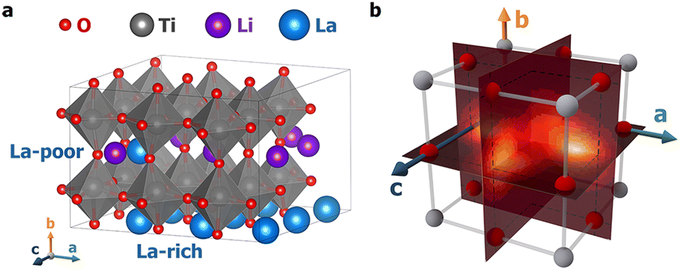 | ||
| Fig. 1 (a) A 3-dimensional representation of the LLTO structure; (b) an illustration of a Ti8 cage where the metadynamics simulations were carried out. Three collective variables were constructed to represent the a, b, and c coordinates of the Li+ ion within the cube; see the main text and ESI† for details. Planar slices of the 3D free-energy profiles normal to the three axes are visualized in Fig. 2, with those at T = 100 K shown here as a visual reference. | ||
To quantify the free energy profiles, first-principles metadynamics simulations16,17 were performed using the Vienna Ab initio Simulation Package (VASP)20,21 with three collective variables (CVs): the relative a, b, and c distances of a tagged Li+ ion from the four O2− ions and four Ti4+ ions on the (100), (010), and (001) surfaces, respectively (see Section SI, ESI†). To ensure thorough sampling of the Li+ ion in the Ti8 cage, a wall of Gaussian restraining potentials was applied at a distance of 1.9 Å outside the cage boundaries so that the Li+ ion does not wander into neighboring Ti8 cages. To visualize the 3D free-energy profiles from the metadynamics simulations, three perpendicular slices were taken that pass through the cage center, as shown in Fig. 1b. Fig. 2 displays the resulting 2D free-energy surfaces at four different temperatures. The (010) surfaces show the free energies of Li+ ions in the La-poor layer, while the (100) and (001) surfaces include contact with the La-rich layers at ξb = 0 and 1. At the two lower temperatures, T = 100 and 300 K, Li+ ions prefer the slightly offset face centers, as discussed above and reflected in the four minima in Fig. 2a and d. However, if the neighboring cages are occupied by La, the corresponding face centers would be extremely unfavorable, reducing the number of minima to two in Fig. 2b, c, e and f. As the temperature increases, the precise positions of the free-energy minima shift further away from the face centers. At T = 700 K, the different free-energy basins begin to merge, which becomes a single minimum located in the body center of the Ti8 cage at T = 1000 K. Tracing the minimum free-energy pathway, Li+ ion hopping at the two lower temperatures would follow a quarter-arc trajectory (indicated by solid lines in Fig. S1, ESI†), as previously found using zero-Kelvin NEB calculations,19 while the mechanism switches to hopping from an A-site cage center to a neighboring cage center (indicated by dashed lines in Fig. S1, ESI†) with the free-energy minima at lower temperatures becoming the transition states at T = 700 and 1000 K.
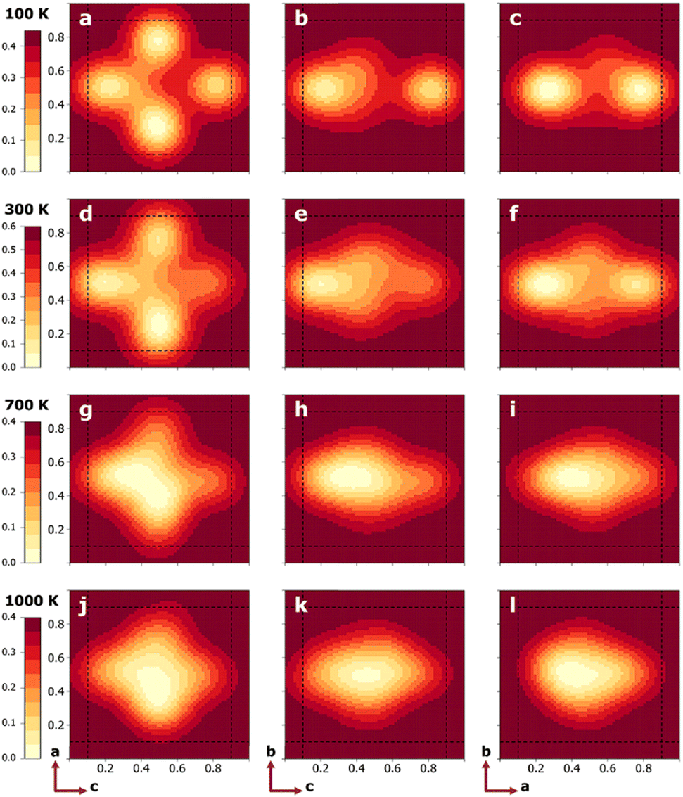 | ||
| Fig. 2 2D free-energy profiles (unit: eV) on center planes indicated in Fig. 1b for T = 100 (a)–(c), 300 (d)–(f), 700 (g)–(i), and 1000 K (j)–(l). The left, middle, and right columns correspond to the (010), (100), and (001) planes, respectively. The dashed lines represent the boundaries of the Ti8 cage. | ||
The unexpected transition in Li+ ion sitting and transport mechanisms can be attributed to a shifting balance of enthalpy and entropy: the 4-fold coordination at the face centers, characterized by Li–O distances of 1.96–2.07 Å, is energetically more favorable than the 12-fold coordination at the body center, characterized by Li–O distances of 2.73–3.07 Å, which leads to a preference for 4-fold coordination at lower temperatures. On the other hand, face centers are more constrained and thus entropically less favorable than the more spacious cage interior. Therefore, at higher temperatures, entropy begins to dominate and the preferred Li+ ion sitting shifts towards body centers. To obtain free-energy barriers for Li+ ion hopping, the 3D free-energy profiles were projected to calculate 1D potentials of mean force (PMFs) along the two types of pathways, quarter arcs (ξ1) and straight lines (ξ2) connecting cage centers (see Section SII and Fig. S1, ESI†).22 The 1D PMFs are shown in Fig. 3. At T = 100 K, pathways 1 and 4 exhibit a free-energy barrier of ΔG‡ ≈ 0.18 eV, while the barrier for pathways 2 and 4 is higher, at ΔG‡ ≈ 0.29 eV. As T increases to 300 K, the increasing probability of finding Li+ in the Ti8 cage interior relative to 100 K leads to a flatter free-energy profile (cf.Fig. 2a and d) and thus a lower hopping free-energy barrier, by about 0.02 eV for pathways 1 and 4. Assuming all quarter arcs have the same free-energy barrier of 0.16 eV at T = 300 K, the rate constant of an elementary Li+ ion hopping event can be calculated using transition-state theory and converted to ionic conductivity (see Section SIII, ESI†). A value of 0.083 S cm−1 was obtained, which is about an order of magnitude higher than a recent measurement of LLTO single crystals.23 It is worth noting that this rough estimate has also ignored the transmission coefficient and the fact that Li+ ion hopping in La-poor layers will be interrupted by occupied La3+ sites, both leading to reduced conductivity.24 At T = 700 K, the cage-to-cage hopping exhibits a barrier of ΔG‡ ≈ 0.20 eV and further increasing the temperature to 1000 K lowers ΔG‡ slightly to 0.17 eV.
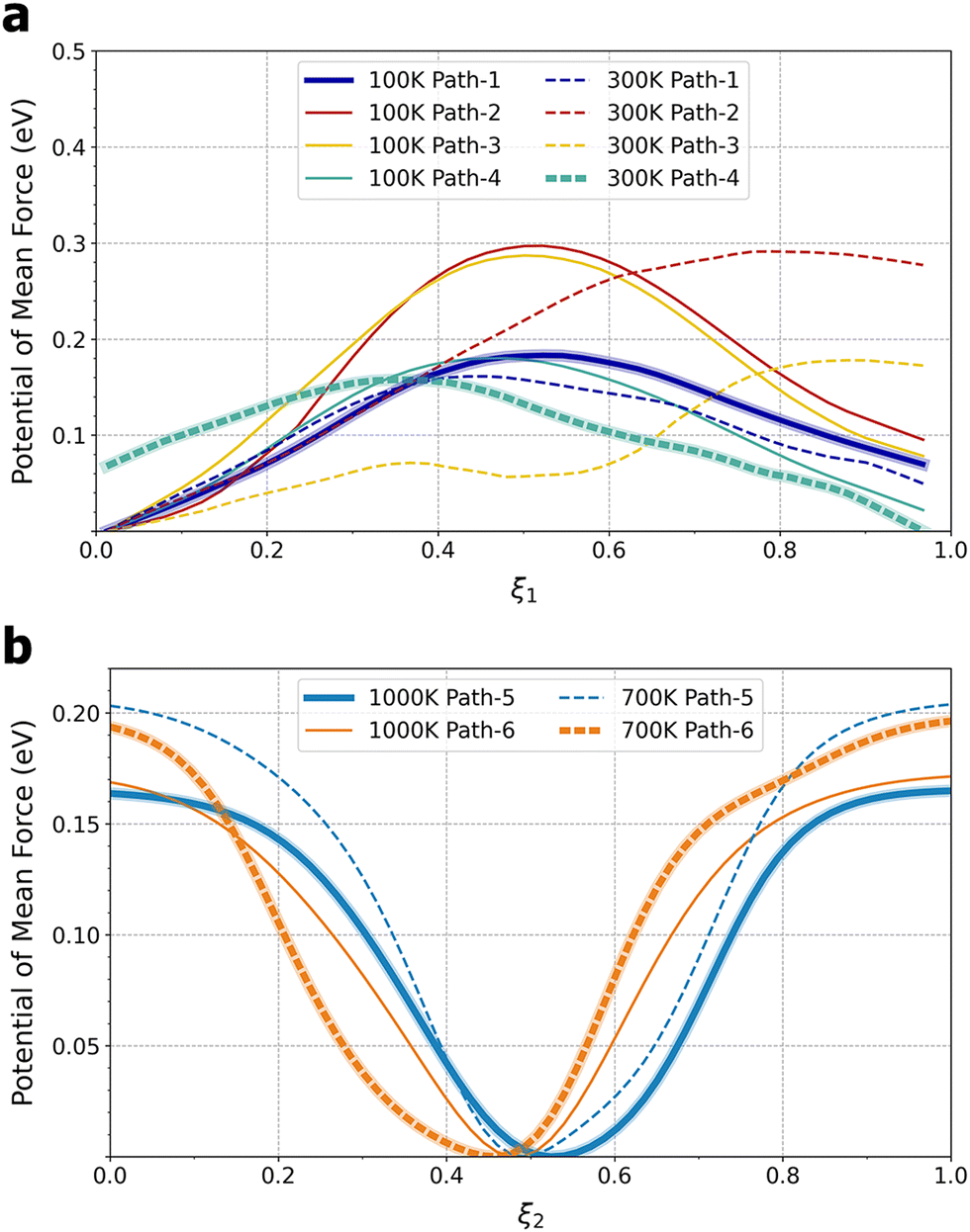 | ||
| Fig. 3 Free-energy profiles along (a) pathways 1–4 at T = 100 and 300 K and (b) pathways 5 and 6 at T = 700 and 1000 K. The bold lines indicate the minimum-free-energy pathways. See Fig. S1 (ESI†) for the definition of pathways. Note that ξ1, as defined by eqn (S4) in the ESI,† does not start at 0 or end at 1. | ||
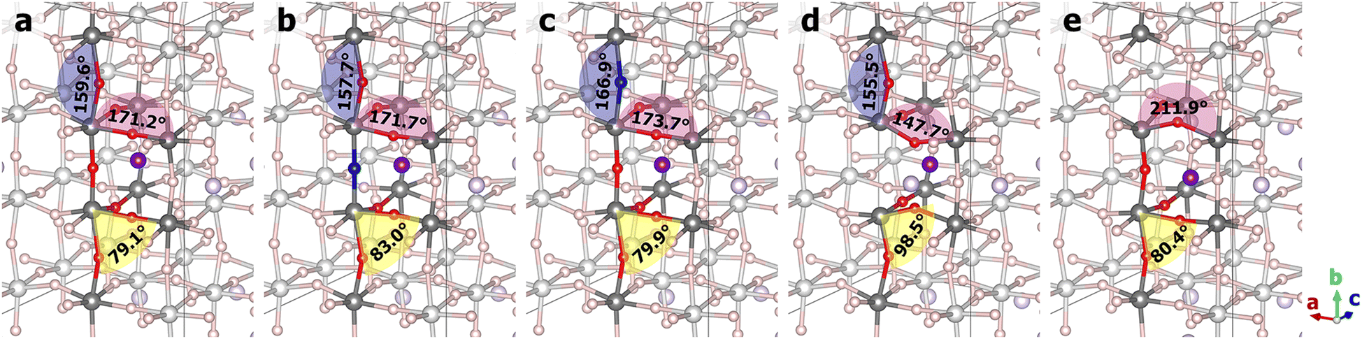
Given that they are suitable to model Li+ ion transport at room temperature, as the next step, NEB methods25,26 were used to calculate the potential energy barriers for Li+ ion hopping in pristine, doped, and defective LLTO. Previously it has been found that anion doping of lattice oxygen atoms by nitrogen increases the ionic conductivity,19 but nitrogen doping inevitably induces the formation of oxygen vacancies, and both doping and vacancy defects can potentially affect Li+ ion transport. Here, by studying five selected structures, including a pristine structure, two nitrogen-doped structures, and two structures with oxygen vacancies, where the dopant and the defect can exist in either La-rich or La-poor layers, we aim to isolate and untangle the effects of doping and vacancies. Fig. 4 compares the potential energy profiles for the five LLTO materials, with panels b–f illustrating the structures and hopping pathways. The energies for the hopping initial states are aligned to zero in Fig. 4a, and their numerical values are given in Table S1 (ESI†). A comparison of energies shows that both the nitrogen dopant and oxygen vacancy have a spatial preference for La-rich layers, albeit to different degrees: La-rich layers are more favorable than La-poor layers by about 0.08 eV and more than 1.2 eV for a single nitrogen dopant and a single oxygen vacancy, respectively. Since Li+ ion transport can only occur within La-poor layers, one might expect that nitrogen doping and oxygen vacancies would have a larger impact in La-poor layers. This is indeed the case with nitrogen doping: as shown in Fig. 4a, the ND@La-rich structure has a barrier of 0.29 eV, nearly identical to that of the pristine structure at 0.28 eV, while the barrier for the ND@La-poor structure is lower by about 0.1 eV, as previously observed.19 In contrast, the effect of oxygen vacancies is much more significant in both La-poor and La-rich layers, with barriers of 0.17 and 0.12 eV, respectively. It is worth noting that long-ranged Li+ ion transport would require multiple consecutive hopping events, and it is therefore important to examine other hopping configurations. In Table S1 (ESI†), the barriers in the reverse direction are also given. Considering the larger values of the two barriers, the ND@La-poor and OV@La-rich structures would have a barrier of 0.19 and 0.15 eV, respectively.
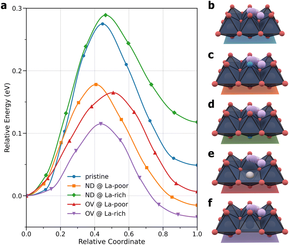 | ||
| Fig. 4 (a) Potential energy profiles for minimum-energy Li+ ion migration pathways in pristine LLTO, LLTO with a nitrogen dopant (ND) in La-poor and La-rich layers, and LLTO with an oxygen vacancy (OV) in the La-poor and La-rich layers. (b)–(f) Illustration of Li+ ion hopping pathways examined for (b) pristine, (c) ND@La-poor, (d) ND@La-rich, (e) OV@La-poor, and (f) OV@La-rich structures. | ||
The varying degrees of change in the Li+ ion hopping barriers can be traced to the structural distortions caused by doping and vacancies, as illustrated in Fig. 5 for the hopping transition states and in Fig. S2–S11 (ESI†) for the initial and final states. A collection of Ti–O–Ti angles that reflect the bending and twisting of TiO8 octahedra are compiled in Table S2 (ESI†). Comparing the two N-doped structures, the oxygen atoms in the same TiO8 octahedron were found to bend towards the nitrogen dopant due to the tendency of nitrogen to have a valency of −3. This is reflected in the Ti1–O11–Ti3, Ti1–O12–Ti5, Ti2–O21–Ti4, and Ti2–O22–Ti6 angles in the ND@La-poor structure that are smaller by 1°–3° than the corresponding angles in the pristine structure. The Ti1–N–Ti2 angle is however closer to 180°. The inward-bending O11, O12, O21, and O22 atoms give rise to more favorable Li–O interactions along the hopping pathway, which are coupled with the weaker Li–N bonding, leading to a lower hopping barrier. In contrast, the various Ti–O–Ti angles in the ND@La-rich structure are substantially more similar as in the pristine structure, presumably due to the occupation of the Ti8 cage by La. Due to the structural similarity, N-doping in La-rich layers therefore has little effect on Li+ ion hopping in the La-poor layer. Next, comparing the two vacancy-containing structures, much larger distortions of the Ti–O–Ti angles were observed. In OV@La-poor, Ti1–O11–Ti3 and Ti1–O12–Ti5 are smaller by 20°–30° than in pristine LLTO, bending towards the Li+ ion (see Fig. 5 and Fig. S5 and S10, ESI†), while Ti2–O21–Ti4, and Ti2–O22–Ti6 are smaller by 10° in the final states (when Li+ coordinates to O21 and O22) but are larger by >10° in the initial and transition states. These geometric changes suggest that the missing Li–O interactions due to oxygen vacancies are somewhat compensated by shorter Li–O bonds. Similar large distortions were found for the OV@La-rich structures. O11 and O12, however, tilt away from the Li+ ion (see Fig. 5 and Fig. S6 and S11, ESI†), weakening the Li–O interactions. Taken together, despite possibly different causes, both structures containing oxygen vacancies exhibit significantly lower hopping barriers.
 | ||
| Fig. 5 Transition-state structures from NEB calculations: (a) pristine; (b) ND@La-poor; (c) ND@La-rich; (d) OV@La-poor; (e) OV@La-rich structures. La ions were hidden for clarity. | ||
To conclude, using ab initio molecular dynamics simulations in combination with metadynamics, the 3D free-energy profiles of Li+ ion hopping were mapped out in solid-state LLTO. By comparing the free-energy profiles over a wide range of temperatures, an unexpected switch of the Li+ ion hopping mechanisms was discovered. At low temperatures (≤300 K), Li+ ions favor the face centers of the Ti-defined cubic lattice with a 4-fold coordination, hopping along quarter arcs connecting such face centers, while at high temperatures (≥700 K), Li+ ions are located preferentially at the body center with a 12-fold coordination, hopping along straight lines parallel to the lattice vectors across different Ti8 cages. With this knowledge, the Li+ ion hopping barriers at low temperature were further calculated using the NEB method for pristine, nitrogen-doped, vacancy-containing LLTO materials, which reveals that nitrogen dopants in the La-poor layer and oxygen vacancies are the key factors to enhanced ionic conductivity. These results provide guidance for the rational design of anion-doped LLTO. At low temperatures, introducing vacancies or nitrogen dopants weakens Li+ interactions with lattice oxygens, thereby “leveling up” the energies of the initial states relative to the transition states, leading to reduced hopping barriers. In contrast, to flatten the hopping free-energy landscape at high temperatures, the design rules may involve strengthening Li+ interactions at the face centers. More broadly, while the findings here support the use of NEB methods for modeling Li+ ion hopping in LLTO, the precise transition temperature between different hopping mechanisms may vary depending on the specific material structures under study. The mechanism switching due to the balance of enthalpy and entropy can be a general phenomenon and observations at high temperatures may offer poor guidance for understanding the ion transport mechanisms under practical conditions.
This work used resources of the National Energy Research Scientific Computing Center (NERSC) through allocation ERCAP0028612 and of the Advanced Cyberinfrastructure Coordination Ecosystem (ACCESS) through allocation CTS190069. PB acknowledges the support from the National Science Foundation (CBET 2144360).
Data availability
The data supporting this article have been included as part of the ESI.† Raw simulation data are available by contacting the corresponding author.Conflicts of interest
There are no conflicts to declare.Notes and references
- J. B. Goodenough and K.-S. Park, J. Am. Chem. Soc., 2013, 135, 1167–1176 CrossRef CAS PubMed.
- M. M. Thackeray, et al., Energy Environ. Sci., 2012, 5, 7854 RSC.
- J. Xie and Y.-C. Lu, Nat. Commun., 2020, 11, 2499 CrossRef CAS PubMed.
- Y.-K. Sun, ACS Energy Lett., 2020, 5, 3221–3223 CrossRef CAS.
- X. Yu, et al., Engineering, 2023, 21, 9–14 CrossRef.
- A. M. Bates, et al., Joule, 2022, 6, 742–755 CrossRef CAS.
- J. C. Bachman, et al., Chem. Rev., 2016, 116, 140–162 CrossRef CAS PubMed.
- Z. Zhang, et al., Energy Environ. Sci., 2018, 11, 1945–1976 RSC.
- S. Hull, Rep. Prog. Phys., 2004, 67, 1233–1314 CrossRef CAS.
- H. Yang and N. Wu, Energy Sci. Eng., 2022, 10, 1643–1671 CrossRef CAS.
- X. He, et al., Nat. Commun., 2017, 8, 15893 CrossRef CAS.
- K. Meier, et al., J. Phys. Chem. C, 2014, 118, 6668–6679 CrossRef CAS.
- X. He, et al., npj Comput. Mater., 2018, 4, 18 CrossRef.
- W. S. Scheld, et al., Adv. Funct. Mater., 2023, 33, 2302939 CrossRef CAS.
- G. Mills, et al., Surf. Sci., 1995, 324, 305–337 CrossRef CAS.
- A. Laio and M. Parrinello, Proc. Natl. Acad. Sci. U. S. A., 2002, 99, 12562–12566 CrossRef CAS PubMed.
- M. Iannuzzi, et al., Phys. Rev. Lett., 2003, 90, 238302 CrossRef PubMed.
- G. M. Torrie and J. P. Valleau, J. Comput. Phys., 1977, 23, 187–199 CrossRef.
- H. Yang, et al., J. Electrochem. Soc., 2021, 168, 110507 CrossRef CAS.
- G. Kresse and J. Furthmüller, Phys. Rev. B: Condens. Matter Mater. Phys., 1996, 54, 11169–11186 CrossRef CAS PubMed.
- G. Kresse and D. Joubert, Phys. Rev. B: Condens. Matter Mater. Phys., 1999, 59, 1758–1775 CrossRef CAS.
- D. Branduardi, et al., J. Comput. Phys., 2007, 126, 054103 Search PubMed.
- S. Kobayashi, et al., Nano Lett., 2022, 22, 5516–5522 CrossRef CAS PubMed.
- P. Bai, et al., ACS Nano, 2016, 10, 7612–7618 CrossRef CAS PubMed.
- H. Jónsson, et al., Classical and Quantum Dynamics in Condensed Phase Simulations, World Scientific, LERICI, Villa Marigola, 1998, pp. 385–404 Search PubMed.
- G. Henkelman, et al., J. Chem. Phys., 2000, 113, 9901–9904 CrossRef CAS.
Footnote |
| † Electronic supplementary information (ESI) available: Computational details and additional figures and tables. See DOI: https://doi.org/10.1039/d4cc02120g |
| This journal is © The Royal Society of Chemistry 2024 |