Covalent organic frameworks based on tetraphenyl-p-phenylenediamine and metalloporphyrin for electrochemical conversion of CO2 to CO†
Lei
Gong
a,
Baotong
Chen
a,
Ying
Gao
a,
Baoqiu
Yu
a,
Yinhai
Wang
a,
Bin
Han
a,
Chenxiang
Lin
b,
Yongzhong
Bian
 *ac,
Dongdong
Qi
*a and
Jianzhuang
Jiang
 *ac
*ac
aBeijing Key Laboratory for Science and Application of Functional Molecular and Crystalline Materials, Department of Chemistry, School of Chemistry and Biological Engineering, University of Science and Technology Beijing, Beijing 100083, China. E-mail: yzbian@ustb.edu.cn; qdd@ustb.edu.cn; jianzhuang@ustb.edu.cn
bGuangxi Key Laboratory of Natural Polymer Chemistry and Physics, Nanning Normal University, Nanning 530001, China
cDaxing Research Institute, and Beijing Advanced Innovation Center for Materials Genome Engineering, University of Science and Technology Beijing, Beijing 100083, China
First published on 25th May 2022
Abstract
Electrocatalytic CO2 reduction provides a possible method for carbon neutralization. Electrode materials with efficient electron transfer, high selectivity and large current density are highly desirable. Herein, we have developed a couple of tetraphenyl-p-phenylenediamine and metalloporphyrin-based 2D COFs for the electrocatalytic CO2 reduction. TPPDA-MPor-COFs (M = Co and Ni) were obtained by the cross-condensation of tetraphenyl-p-phenylenediamine (TPPDA) and 5,10,15,20-tetrakis(4-formylphenyl)-metalloporphyrin (MPor). The as-prepared TPPDA-CoPor-COF shows high CO faradaic efficiencies of 87–90% from −0.6 to −0.9 V vs. RHE, and the largest CO partial current density (jCO) of TPPDA-CoPor-COF (−22.2 mA cm−2 at −1.0 V vs. RHE) exceeds those of most of the reported COF-based electrocatalysts. Notably, exfoliated TPPDA-CoPor-COF nanosheets (TPPDA-CoPor-COF-NSs) show much better electrocatalytic performance. The CO faradaic efficiencies of TPPDA-CoPor-COF-NSs are over 90% in a wider voltage range (−0.7 to −0.9 V), and the maximum jCO reaches up to −29.2 mA cm−2 at −1.0 V. Density functional theory calculations have been performed to rationalize the improved CO2RR performance of TPPDA-CoPor-COF.
Introduction
In order to achieve carbon neutralization, photocatalysis,1–3 electrocatalysis4–6 and thermal catalysis7 have been developed over the past decades. The electrocatalytic CO2 reduction reaction (CO2RR) is considered as a promising strategy among them, which is clean and mild and can be associated with renewable energy.8,9 Varieties of homogeneous and heterogeneous catalysts have been developed for the efficient and selective electrocatalytic CO2RR.10–17 Although homogeneous catalysts have been proved to show low overpotential and high selectivity by means of smart design and functional group regulation,11 inefficient electron transfer and poor stability in homogeneous organic catalytic systems restrain their practical application. Meanwhile, due to their aqueous compatibility and great catalytic activity, various heterogeneous catalysts have been investigated.18,19As promising porous crystalline materials, metal–organic frameworks (MOFs)20–22 and covalent organic frameworks (COFs)23,24 have been explored for the electrocatalytic CO2RR. In particular, the building blocks of COFs can be manipulated precisely for specific activity and selectivity. Some active homogeneous molecular catalysts, such as porphyrins25–31 and phthalocyanines,32–34 could be integrated into COFs as building blocks for the electrocatalytic CO2RR. Nevertheless, most of the reported COF materials exhibit limited current density and relatively low faradaic efficiency. Hence, novel COFs with high current density and excellent energy conversion efficiency are highly desirable.
Tetraphenyl-p-phenylenediamine, as a typical electron donor, has a high electron transfer capability and has been widely used in preparing electrochemically active materials.35–39 On the other hand, metalloporphyrins (MPor) can function as excellent electron acceptors and charge transfer components due to their conjugated macrocyclic structures.27–29,40–42 Therefore, efficient intramolecular electron transfer paths might be constructed by integrating TPPDA and MPor into two-dimensional COFs, and enhanced electrocatalytic CO2RR activities are expected for the obtained COFs.
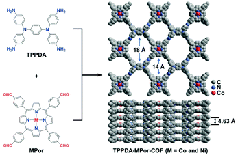
Herein, MPor and TPPDA-based COFs (TPPDA-MPor-COFs, M = Co(II) and Ni(II)) have been synthesized for the first time (Fig. 1). TPPDA-CoPor-COF exhibits high CO faradaic efficiencies (FECO) and large CO partial current densities (jCO), which can be further improved by physical ultrasonic exfoliation. The obtained TPPDA-CoPor-COF nanosheets (TPPDA-CoPor-COF-NSs) show a maximum FECO of 92% at −0.7 V and a jCO of −29.2 mA cm−2 at −1.0 V vs. RHE. The excellent electrocatalytic properties can be attributed to the large amount of accessible Co(II) sites and efficient electron transfer from TPPDA to CoPor blocks in these COF-based materials.
Results and discussion
Synthesis and characterization
TPPDA-MPor-COFs (M = Co and Ni) were synthesized via Schiff-base condensation of TPPDA and MPor (M = Co and Ni). The experimental powder X-ray diffraction (PXRD) patterns show that TPPDA-MPor-COFs have good crystallinity (Fig. 2a and S1†). Le Bail refinements of TPPDA-MPor-COFs were carried out on the basis of experimental PXRD data (Fig. S2†).43 Eclipsed (AA) and staggered (AB) stacking models of TPPDA-CoPor-COF were constructed, where the former one matches well with the experimental data. Furthermore, the refined results of TPPDA-CoPor-COF show low residual values (Rp = 5.04% and Rwp = 7.50%) indicating the validity of the AA stacking model. The unit cell information of TPPDA-CoPor-COF has been obtained as follows: triclinic P1 space group, a = 24.56 Å, b = 25.08 Å and c = 4.63 Å, α = 66.76°, β = 104.04°, γ = 90.83°. In the experimental PXRD pattern of TPPDA-CoPor-COF (Fig. 2a), the strong diffraction signals at 3.77°, 5.09° and 5.54° are assigned to the (100), (110) and (1−10) planes, respectively. A couple of weak signals at 10.20° and 11.12° are attributed to the (220) and (130) planes, respectively. TPPDA-NiPor-COF (Fig. S1†) shows similar PXRD results.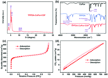 | ||
| Fig. 2 (a) Experimental PXRD patterns, (b) FT-IR spectra, (c) N2 sorption isotherm at 77 K and (d) CO2 sorption isotherm at 298 K for TPPDA-CoPor-COF. | ||
In the FT-IR spectra of TPPDA-MPor-COFs (Fig. 2b and S3†), the peaks at 1622 cm−1 reveal that the imine bond (C![[double bond, length as m-dash]](https://www.rsc.org/images/entities/char_e001.gif) N) formed successfully, along with a decrease of C
N) formed successfully, along with a decrease of C![[double bond, length as m-dash]](https://www.rsc.org/images/entities/char_e001.gif) O (1699 cm−1) and N–H (3458–3348 cm−1 and 1620 cm−1) vibrations for MPor and TPPDA monomers, respectively.44 In the solid-state electronic absorption spectrum, the characteristic absorptions of the MPor moiety (i.e. Q-band, 541 nm; sorbet band 432 nm) can be observed, suggesting the successful integration of the cobalt porphyrin unit into TPPDA-CoPor-COF (Fig. S4†).
O (1699 cm−1) and N–H (3458–3348 cm−1 and 1620 cm−1) vibrations for MPor and TPPDA monomers, respectively.44 In the solid-state electronic absorption spectrum, the characteristic absorptions of the MPor moiety (i.e. Q-band, 541 nm; sorbet band 432 nm) can be observed, suggesting the successful integration of the cobalt porphyrin unit into TPPDA-CoPor-COF (Fig. S4†).
The XPS spectra reveal the presence of C, N and Co/Ni elements in the two COFs (Fig. S5a and S6a†), and the two COFs show three characteristic peaks corresponding to the C–N (pyrrolic nitrogen) bond (398.6 and 398.7 eV) of MPor, and the C![[double bond, length as m-dash]](https://www.rsc.org/images/entities/char_e001.gif) N bond (399.0 and 399.1 eV) and the C–N bond (399.6 eV) of TPPDA, respectively (Fig. S5b and S6b†), further indicating the formation of the imine bond.45 In addition, the XPS analyses of Co 2p and Ni 2p indicate that all the metal sites in TPPDA-MPor-COFs are divalent (Fig. S5c and S6c†).46,47 The N2 sorption curves of the two COFs display type I-isotherms (Fig. 2c and S8†). The adsorption curves show a steep increase when P/P0 < 0.01, corresponding to the presence of permanent micropores. The Brunauer–Emmett–Teller (BET) surface area and the total pore volume of TPPDA-CoPor-COF were 1209 m2 g−1 and 0.99 cm3 g−1, respectively (Fig. 2c). TPPDA-CoPor-COF displays two pore sizes (1.2 nm and 1.5 nm) (Fig. S7†), being consistent with the simulated structure (Fig. 1). TPPDA-NiPor-COF shows similar N2 sorption and porous properties (Fig. S8† and S9†). Besides, TPPDA-CoPor-COF and TPPDA-NiPor-COF show moderate CO2 sorption capacities of 26.8 cm3 g−1 and 28.1 cm3 g−1 at 25 °C and 1.0 bar, respectively (Fig. 2d and S10†), indicating the CO2 affinity of TPPDA-MPor-COFs.
N bond (399.0 and 399.1 eV) and the C–N bond (399.6 eV) of TPPDA, respectively (Fig. S5b and S6b†), further indicating the formation of the imine bond.45 In addition, the XPS analyses of Co 2p and Ni 2p indicate that all the metal sites in TPPDA-MPor-COFs are divalent (Fig. S5c and S6c†).46,47 The N2 sorption curves of the two COFs display type I-isotherms (Fig. 2c and S8†). The adsorption curves show a steep increase when P/P0 < 0.01, corresponding to the presence of permanent micropores. The Brunauer–Emmett–Teller (BET) surface area and the total pore volume of TPPDA-CoPor-COF were 1209 m2 g−1 and 0.99 cm3 g−1, respectively (Fig. 2c). TPPDA-CoPor-COF displays two pore sizes (1.2 nm and 1.5 nm) (Fig. S7†), being consistent with the simulated structure (Fig. 1). TPPDA-NiPor-COF shows similar N2 sorption and porous properties (Fig. S8† and S9†). Besides, TPPDA-CoPor-COF and TPPDA-NiPor-COF show moderate CO2 sorption capacities of 26.8 cm3 g−1 and 28.1 cm3 g−1 at 25 °C and 1.0 bar, respectively (Fig. 2d and S10†), indicating the CO2 affinity of TPPDA-MPor-COFs.
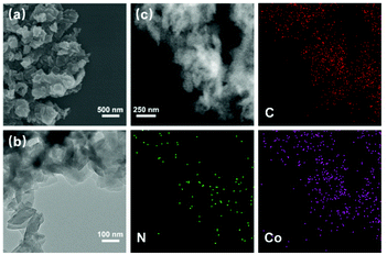
The scanning electron microscopy (SEM) and transmission electron microscopy (TEM) images show that TPPDA-MPor-COFs have layered morphologies with sizes of 100–500 nm (Fig. 3a, b and S11†). The element energy dispersive spectroscopy (EDS) mapping images (Fig. 3c and S12†) show the uniform distribution of metal ions (Co or Ni), C and N elements in TPPDA-CoPor-COF and TPPDA-NiPor-COF, respectively. The total Co content (3.35%) of TPPDA-CoPor-COF and Ni content (3.20%) of TPPDA-CoPor-COF were measured by ICP tests (Table S1†), and are reasonably lower than the calculated metal contents. Thermal gravimetric analyses (TGAs) were carried out under a nitrogen atmosphere (Fig. S13†). TPPDA-MPor-COFs only displayed a slight weight loss till 500 °C owing to the loss of residual solvents, suggesting the high thermal stability of the COFs.
The Co K-edge XANES spectra of TPPDA-CoPor-COF and CoPc exhibit similar curves, suggesting that the coordination environment of Co atoms in TPPDA-CoPor-COF are the same as that of CoPc (Fig. 4a). In the Fourier-transform (FT) EXAFS curves, TPPDA-CoPor-COF displays a strong signal at 1.53 Å corresponding to the Co–N scattering path (Fig. 4b),48 and no signal of Co–Co bonds was detected. EXAFS fitting for TPPDA-CoPor-COF was conducted using Co–N4 coordination models. The result also suggests that the Co site in TPPDA-CoPor-COF is coordinated with four nitrogen atoms (Fig. 4c and Table S2†). TPPDA-NiPor-COF shows similar results (Fig. S14†).
 | ||
| Fig. 4 (a) Co K-edge XANES spectra of TPPDA-CoPor-COF, CoPc, CoO and Co foil. (b) FT EXAFS spectra of TPPDA-CoPor-COF, CoPc, CoO and Co foil. (c) The EXAFS fitting curve of TPPDA-CoPor-COF. | ||
Electrocatalytic performance
To investigate the catalytic performances of the COFs, a H-cell with a standard three-electrode system and 0.5 M KHCO3 electrolyte solution was used. In order to avoid the accidental factors, three parallel experiments were conducted. All potentials are presented relative to the reversible hydrogen electrode (RHE) in this work.Linear sweep voltammetry (LSV) curves were obtained in CO2 and Ar-saturated 0.5 M KHCO3, respectively (Fig. 5a). The onset potential of TPPDA-CoPor-COF (−0.46 V) is more positive than that of TPPDA-NiPor-COF (−0.72 V). TPPDA-CoPor-COF also exhibits larger current densities in CO2-saturated solution than in Ar-saturated solution from −0.5 to −1.0 V, suggesting greater electrocatalytic CO2RR activity than the hydrogen evolution reaction (HER) activity. Short-term electrolysis tests and the corresponding gas chromatography analyses show that the products of the electrocatalytic CO2RR were carbon monoxide and hydrogen (Fig. S15 and S16†). The nuclear magnetic resonance experiment shows that no liquid product is generated during the reduction process (Fig. S17†). Only a negligible amount of CO was detected when the control electrolysis was conducted in an Ar-saturated 0.5 M KHCO3 electrolyte (Fig. S18†). Furthermore, carbon cloth decorated with Vulcan XC-72R carbon black and Nafion shows almost no electrocatalytic CO2RR activity in the CO2-saturated electrolyte (Fig. S19†). According to the above results, the source of CO and the electrocatalytic CO2RR activity of TPPDA-CoPor-COF can be confirmed.
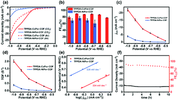 | ||
| Fig. 5 (a) LSV curves, (b) FEco, (c) jCO, (d) TOF and (e) Tafel plots of TPPDA-MPor-COFs. (f) Lasting stability test for TPPDA-CoPor-COF at −0.8 V. | ||
TPPDA-CoPor-COF exhibits high CO faradaic efficiencies (FECO) of 87–90% in the range of −0.6 to −0.9 V (Fig. 5b), while TPPDA-NiPor-COF shows lower FECO (i.e. 60–76% in −0.7 to −0.9 V). The jCO values of TPPDA-CoPor-COF increase with elevated applied potential and reach up to −22.2 mA cm−2 at −1.0 V, which is 5.7-fold that of TPPDA-NiPor-COF (−3.9 mA cm−2) (Fig. 5c) and surpasses most of the reported COFs (Fig. S20 and Table S3†). Moreover, in comparison with TPPDA-CoPor-COF, the maximum FECO of the CoPor monomer is only 76% at −0.8 V, and the maximum jCO value is only −11.8 mA cm−2 at −1.0 V (Fig. S21†), and the TPPDA monomer shows nearly 100% FE of H2 in the range of −0.7 to −1.0 V (Fig. S22†). The above results indicate that the TPPDA unit plays an important role in promoting the electrocatalytic CO2RR activity of TPPDA-CoPor-COF. Besides, the turnover frequency (TOF) of TPPDA-CoPor-COF was calculated to be 1.4 s−1 at −0.9 V and 2.0 s−1 at −1.0 V (Fig. 5d).
The Tafel slopes of TPPDA-CoPor-COF and TPPDA-NiPor-COF are tested to be 224 mV dec−1 and 226 mV dec−1, respectively (Fig. 5e). The results imply the slightly superior reactivity of Co over Ni sites. The Nyquist plots of the electrochemical impedance test illustrate that TPPDA-CoPor-COF has a smaller charge-transfer resistance than TPPDA-NiPor-COF during the electrocatalytic CO2RR process (Fig. S23†), confirming its more efficient electron transfer from the catalyst surface to the CO2 molecules. To compare the electrochemically active surface areas (ECSAs) of TPPDA-MPor-COFs, electrochemical double-layer capacitances (Cdl) were acquired (Fig. S24†). TPPDA-CoPor-COF presents a Cdl value of 2.61 mF cm−2, which is larger than 1.31 mF cm−2 for TPPDA-NiPor-COF, further indicating that TPPDA-CoPor-COF shows higher inherent catalytic activity.
Chronoamperometric tests were performed for TPPDA-CoPor-COF to evaluate the durability at −0.8 V in the H-cell. The corresponding FECO values remained higher than 80% in the 10 h electrolysis experiment (Fig. 5f), demonstrating that TPPDA-CoPor-COF has an acceptable electrochemical catalytic stability in spite of a decrease of the current density (∼20%). The stability of TPPDA-CoPor-COF was further demonstrated by the almost unchanged XPS (Fig. S25†) and PXRD (Fig. S26†) data after 2 h and 10 h of electrocatalysis at −0.8 V. The SEM and TEM (Fig. S27†) images of TPPDA-CoPor-COF after 2 h and 10 h of electrolysis suggest that the layered morphology of the catalysts is retained well. The above results well disclose its good electrochemical catalytic stability.
Based on previous reports,27,28 the high stability and performance of two-dimensional TPPDA-CoPor-COF motivated us to ultrasonically exfoliate the materials to further improve their catalytic activity. TPPDA-CoPor-COF was converted into TPPDA-CoPor-COF-NSs with a thin-layered morphology (Fig. S28†) and a thickness of ∼7 nm as proved by atomic force microscopy (AFM) measurements (Fig. 6a and b). Almost identical PXRD curves indicated that the periodic structure of TPPDA-CoPor-COF was retained in the nanosheets after ultrasonic exfoliation (Fig. S29†). To evaluate the electrocatalytic CO2RR performance of TPPDA-CoPor-COF-NSs, the same short- and long-term electrolysis tests were conducted (Fig. S30 and S31†), and the corresponding FECO and jCO were calculated. The FECO values of TPPDA-CoPor-COF-NSs are above 90% in a wider range (−0.7 to −0.9 V) than those of TPPDA-CoPor-COF (Fig. 6c). The maximum FECO value of TPPDA-CoPor-COF-NSs is 92% at −0.7 V and the jCO reaches up to −29.2 mA cm−2 at −1.0 V (Fig. 6d), which are higher than those of the unexfoliated one. The promoted CO2RR performance of TPPDA-CoPor-COF-NSs could be attributed to the more exposed Co active sites.27,28 Besides, a 10 h chronoamperometric test of the nanosheets at −0.7 V was carried out. Same as the unexfoliated one, the corresponding FECO can be kept above 80% in the whole electrolysis process as well (Fig. S29†), indicating that TPPDA-CoPor-COF-NSs also have tolerable electrochemical catalytic stability, although accompanied by a certain degree of current density attenuation.
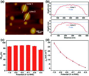 | ||
| Fig. 6 (a) The atomic force microscopy topographical image. (b) Corresponding height curves of (a). (c) FECO of TPPDA-CoPor-COF-NSs. (d) Lasting stability test of TPPDA-CoPor-COF-NSs at −0.7 V. | ||
DFT calculations
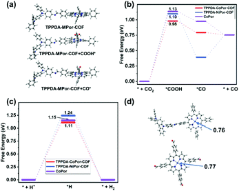
The frontier molecular orbitals of the repeat unit in TPPDA-MPor-COFs were calculated by DFT calculations (Fig. S32 and S33†). The HOMO is located on the TPPDA moiety, while the LUMO is on the MPor moiety, implying the electronic donor–acceptor configuration of the two COFs, which usually means decreased band gaps and enhanced electron transfer properties for organic semiconductors.To understand the superior CO2RR performance of TPPDA-CoPor-COF, the CO2RR and HER mechanisms were calculated together with those of TPPDA-NiPor-COF and the CoPor monomer (Fig. 7a–c). According to the calculated relative free energies, the rate determining steps (RDSs) for the CO2RR and HER are the formation of *COOH and *H intermediates, respectively.49 The ΔGRDS values of the CO2RR for TPPDA-CoPor-COF (0.98 eV), TPPDA-NiPor-COF (1.10 eV) and CoPor (1.13 eV) are all lower than the respective ΔGRDS values of the HER (1.11 eV, 1.24 eV, and 1.15 eV), indicating their preferable CO2RR activity. TPPDA-CoPor-COF exhibits dramatically reduced ΔGRDS of the CO2RR relative to the CoPor monomer, suggesting that the introduction of the TPPDA unit and the formation of COFs could promote the CO2RR activity of the CoPor core. Mulliken population and frontier orbital analyses afforded consistent results (Fig. 7d and Fig. S34†).50 The Mulliken atom charge of the Co sites in TPPDA-CoPor-COF (0.76) is lower than that in the CoPor monomer (0.77), indicating the more electron-rich environment of the Co atom in TPPDA-CoPor-COF. The LUMO level of TPPDA-CoPor is −2.29 eV, which is higher than that of CoPor (−2.42 eV), suggesting the higher reducibility of TPPDA-CoPor-COF in the electrocatalytic process. TPPDA-NiPor-COF displays a higher ΔGRDS of the CO2RR than that of TPPDA-CoPor-COF, suggesting the harder formation of *COOH intermediates on TPPDA-NiPor-COF. Furthermore, the desorption of CO from TPPDA-NiPor-COF (*CO → *+CO) is endothermic, while this step for TPPDA-CoPor-COF is exothermic (Fig. 7b), indicating that the Co site shows superior CO2RR activity than the Ni site in the COFs, which is consistent with the experimental results.
Conclusions
In summary, metalloporphyrin- and TPPDA-based two-dimensional COFs were explored for the electrocatalytic CO2RR in the H-cell. The obtained TPPDA-CoPor-COF exhibits a high FECO of 87–90% in the range of −0.6 to −0.9 V and a maximum jCO of −22.2 mA cm−2 at −1.0 V. The exfoliated TPPDA-CoPor-COF-NSs show further improved FECO and jCO than the as-prepared TPPDA-CoPor-COF. DFT calculations reveal that the integration of the TPPDA block enhances the electron transfer ability of TPPDA-MPor-COFs and reduces the CO2RR energy barrier of the CoPor core. This work would be conducive to the rationally designed novel COF-based electrocatalysts towards the CO2RR.Author contributions
Lei Gong, Baotong Chen, Ying Gao and Yinhai Wang performed experiments under the guidance of Yongzhong Bian and Jianzhuang Jiang. Dongdong Qi, Bin Han, Chenxiang Lin and Baoqiu Yu provided assistance for data acquisition and analysis. All authors discussed the results and commented on the manuscript.Conflicts of interest
There are no conflicts to declare.Acknowledgements
The financial support from the National Natural Science Foundation of China (21631003), Beijing Natural Science Foundation (2202028) and Fundamental Research Funds for the Central Universities (FRF-BD-20-14A) is gratefully acknowledged.Notes and references
- Z. Fu, X. Wang, A. M. Gardner, X. Wang, S. Y. Chong, G. Neri, A. J. Cowan, L. Liu, X. Li, A. Vogel, R. Clowes, M. Bilton, L. Chen, R. S. Sprick and A. I. Cooper, A stable covalent organic framework for photocatalytic carbon dioxide reduction, Chem. Sci., 2020, 11, 543–550 RSC.
- Y. Gong, W. Zhong, Y. Li, Y. Qiu, L. Zheng, J. Jiang and H. Jiang, Regulating Photocatalysis by Spin-State Manipulation of Cobalt in Covalent Organic Frameworks, J. Am. Chem. Soc., 2020, 142, 16723–16731 CrossRef CAS PubMed.
- W. Liu, X. Li, C. Wang, H. Pan, W. Liu, K. Wang, Q. Zeng, R. Wang and J. Jiang, A Scalable General Synthetic Approach toward Ultrathin Imine-Linked Two-Dimensional Covalent Organic Framework Nanosheets for Photocatalytic CO2 Reduction, J. Am. Chem. Soc., 2019, 141, 17431–17440 CrossRef CAS PubMed.
- S. Ren, D. Joulié, D. Salvatore, K. Torbensen, M. Wang, M. Robert and C. P. Berlinguette, Molecular electrocatalysts can mediate fast, selective CO2 reduction in a flow cell, Science, 2019, 365, 367–369 CrossRef CAS PubMed.
- F. P. García De Arquer, C. Dinh, A. Ozden, J. Wicks, C. Mccallum, A. R. Kirmani, D. Nam, C. Gabardo, A. Seifitokaldani, X. Wang, Y. C. Li, F. Li, J. Edwards, L. J. Richter, S. J. Thorpe, D. Sinton and E. H. Sargent, CO2 electrolysis to multicarbon products at activities greater than 1 A cm−2, Science, 2020, 367, 661–666 CrossRef PubMed.
- Z. Liang, H. Wang, H. Zheng, W. Zhang and R. Cao, Porphyrin-based frameworks for oxygen electrocatalysis and catalytic reduction of carbon dioxide, Chem. Soc. Rev., 2021, 50, 2540–2581 RSC.
- S. Kattel, P. Liu and J. G. Chen, Tuning Selectivity of CO2 Hydrogenation Reactions at the Metal/Oxide Interface, J. Am. Chem. Soc., 2017, 139, 9739–9754 CrossRef CAS PubMed.
- N. M. Haegel, R. Margolis, T. Buonassisi, D. Feldman, A. Froitzheim, R. Garabedian, M. Green, S. Glunz, H. Henning, B. Holder, I. Kaizuka, B. Kroposki, K. Matsubara, S. Niki, K. Sakurai, R. A. Schindler, W. Tumas, E. R. Weber, G. Wilson, M. Woodhouse and S. Kurtz, Terawatt-scale photovoltaics: Trajectories and challenges, Science, 2017, 356, 141–143 CrossRef CAS PubMed.
- S. Nitopi, E. Bertheussen, S. B. Scott, X. Liu, A. K. Engstfeld, S. Horch, B. Seger, I. E. L. Stephens, K. Chan, C. Hahn, J. K. Nørskov, T. F. Jaramillo and I. Chorkendorff, Progress and Perspectives of Electrochemical CO2 Reduction on Copper in Aqueous Electrolyte, Chem. Rev., 2019, 119, 7610–7672 CrossRef CAS PubMed.
- E. E. Benson, C. P. Kubiak, A. J. Sathrum and J. M. Smieja, Electrocatalytic and homogeneous approaches to conversion of CO2 to liquid fuels, Chem. Soc. Rev., 2009, 38, 89–99 RSC.
- R. Francke, B. Schille and M. Roemelt, Homogeneously Catalyzed Electroreduction of Carbon Dioxide-Methods, Mechanisms, and Catalysts, Chem. Rev., 2018, 118, 4631–4701 CrossRef CAS PubMed.
- X. Huang and Y. Zhang, Reticular materials for electrochemical reduction of CO2, Coord. Chem. Rev., 2021, 427, 213564 CrossRef CAS.
- Y. Wu, Z. Jiang, X. Lu, Y. Liang and H. Wang, Domino electroreduction of CO2 to methanol on a molecular catalyst, Nature, 2019, 575, 639–642 CrossRef CAS PubMed.
- W. Yang, J. Zhang, R. Si, L. Cao, D. Zhong and T. Lu, Efficient and steady production of 1:2 syngas (CO/H2) by simultaneous electrochemical reduction of CO2 and H2O, Inorg. Chem. Front., 2021, 8, 1695–1701 RSC.
- P. T. Smith, B. P. Benke, Z. Cao, Y. Kim, E. M. Nichols, K. Kim and C. J. Chang, Iron Porphyrins Embedded into a Supramolecular Porous Organic Cage for Electrochemical CO2 Reduction in Water, Angew. Chem., Int. Ed., 2018, 57, 9684–9688 CrossRef CAS PubMed.
- J. Han, P. An, S. Liu, X. Zhang, D. Wang, Y. Yuan, J. Guo, X. Qiu, K. Hou, L. Shi, Y. Zhang, S. Zhao, C. Long and Z. Tang, Reordering d Orbital Energies of Single–Site Catalysts for CO2 Electroreduction, Angew. Chem., Int. Ed., 2019, 58, 12711–12716 CrossRef CAS PubMed.
- Y. Zhang, C. Cao, X. Wu and Q. Zhu, Three-dimensional porous copper-decorated bismuth-based nanofoam for boosting the electrochemical reduction of CO2 to formate, Inorg. Chem. Front., 2021, 8, 2461–2467 RSC.
- S. Gao, Y. Lin, X. Jiao, Y. Sun, Q. Luo, W. Zhang, D. Li, J. Yang and Y. Xie, Partially oxidized atomic cobalt layers for carbon dioxide electroreduction to liquid fuel, Nature, 2016, 529, 68–71 CrossRef CAS PubMed.
- X. Zhang, Y. Wang, M. Gu, M. Wang, Z. Zhang, W. Pan, Z. Jiang, H. Zheng, M. Lucero, H. Wang, G. E. Sterbinsky, Q. Ma, Y. Wang, Z. Feng, J. Li, H. Dai and Y. Liang, Molecular engineering of dispersed nickel phthalocyanines on carbon nanotubes for selective CO2 reduction, Nat. Energy, 2020, 5, 684–692 CrossRef CAS.
- P. Shao, L. Yi, S. Chen, T. Zhou and J. Zhang, Metal-organic frameworks for electrochemical reduction of carbon dioxide: The role of metal centers, J. Energy Chem., 2020, 40, 156–170 CrossRef.
- E. Zhang, T. Wang, K. Yu, J. Liu, W. Chen, A. Li, H. Rong, R. Lin, S. Ji, X. Zheng, Y. Wang, L. Zheng, C. Chen, D. Wang, J. Zhang and Y. Li, Bismuth Single Atoms Resulting from Transformation of Metal-Organic Frameworks and Their Use as Electrocatalysts for CO2 Reduction, J. Am. Chem. Soc., 2019, 141, 16569–16573 CrossRef CAS PubMed.
- H. Zhong, M. Ghorbani-Asl, K. H. Ly, J. Zhang, J. Ge, M. Wang, Z. Liao, D. Makarov, E. Zschech, E. Brunner, I. M. Weidinger, J. Zhang, A. V. Krasheninnikov, S. Kaskel, R. Dong and X. Feng, Synergistic electroreduction of carbon dioxide to carbon monoxide on bimetallic layered conjugated metal-organic frameworks, Nat. Commun., 2020, 11, 1409 CrossRef CAS PubMed.
- J. Li, X. Jing, Q. Li, S. Li, X. Gao, X. Feng and B. Wang, Bulk COFs and COF nanosheets for electrochemical energy storage and conversion, Chem. Soc. Rev., 2020, 49, 3364–3565 Search PubMed.
- Y. Yusran, Q. Fang and V. Valtchev, Electroactive Covalent Organic Frameworks: Design, Synthesis, and Applications, Adv. Mater., 2020, 32, 2002038 CrossRef CAS PubMed.
- S. Lin, C. S. Diercks, Y. B. Zhang, N. Kornienko, E. M. Nichols, Y. Zhao, A. R. Paris, D. Kim, P. Yang, O. M. Yaghi and C. J. Chang, Covalent organic frameworks comprising cobalt porphyrins for catalytic CO2 reduction in water, Science, 2015, 349, 1208–1213 CrossRef CAS PubMed.
- H. Liu, J. Chu, Z. Yin, X. Cai, L. Zhuang and H. Deng, Covalent Organic Frameworks Linked by Amine Bonding for Concerted Electrochemical Reduction of CO2, Chem, 2018, 4, 1696–1709 CAS.
- H. Zhu, M. Lu, Y. Wang, S. Yao, M. Zhang, Y. Kan, J. Liu, Y. Chen, S. Li and Y. Lan, Efficient electron transmission in covalent organic framework nanosheets for highly active electrocatalytic carbon dioxide reduction, Nat. Commun., 2020, 11, 497 CrossRef CAS PubMed.
- Q. Wu, M. J. Mao, Q. J. Wu, J. Liang, Y. B. Huang and R. Cao, Construction of Donor-Acceptor Heterojunctions in Covalent Organic Framework for Enhanced CO2 Electroreduction, Small, 2021, 17, 2004933 CrossRef CAS PubMed.
- S. An, C. Lu, Q. Xu, C. Lian, C. Peng, J. Hu, X. Zhuang and H. Liu, Constructing Catalytic Crown Ether-Based Covalent Organic Frameworks for Electroreduction of CO2, ACS Energy Lett., 2021, 6, 3496–3502 CrossRef CAS.
- E. M. Johnson, R. Haiges and S. C. Marinescu, Covalent-Organic Frameworks Composed of Rhenium Bipyridine and Metal Porphyrins: Designing Heterobimetallic Frameworks with Two Distinct Metal Sites, ACS Appl. Mater. Interfaces, 2018, 10, 37919–37927 CrossRef CAS PubMed.
- P. L. Cheung, S. K. Lee and C. P. Kubiak, Facile Solvent-Free Synthesis of Thin Iron Porphyrin COFs on Carbon Cloth Electrodes for CO2 Reduction, Chem. Mater., 2019, 31, 1908–1919 CrossRef CAS.
- N. Huang, K. H. Lee, Y. Yue, X. Xu, S. Irle, Q. Jiang and D. Jiang, A Stable and Conductive Metallophthalocyanine Framework for Electrocatalytic Carbon Dioxide Reduction in Water, Angew. Chem., Int. Ed., 2020, 59, 16587–16593 CrossRef CAS PubMed.
- B. Han, X. Ding, B. Yu, H. Wu, W. Zhou, W. Liu, C. Wei, B. Chen, D. Qi, H. Wang, K. Wang, Y. Chen, B. Chen and J. Jiang, Two-Dimensional Covalent Organic Frameworks with Cobalt(II)-Phthalocyanine Sites for Efficient Electrocatalytic Carbon Dioxide Reduction, J. Am. Chem. Soc., 2021, 143, 7104–7113 CrossRef CAS PubMed.
- Y. Yue, P. Cai, K. Xu, H. Li, H. Chen, H. Zhou and N. Huang, Stable Bimetallic Polyphthalocyanine Covalent Organic Frameworks as Superior Electrocatalysts, J. Am. Chem. Soc., 2021, 143, 18052–18060 CrossRef CAS PubMed.
- Q. Hao, Z. J. Li, B. Bai, X. Zhang, Y. W. Zhong, L. J. Wan and D. Wang, A Covalent Organic Framework Film for Three–State Near–Infrared Electrochromism and a Molecular Logic Gate, Angew. Chem., Int. Ed., 2021, 60, 12498–12503 CrossRef CAS PubMed.
- J. M. Rotter, R. Guntermann, M. Auth, A. Mähringer, A. Sperlich, V. Dyakonov, D. D. Medina and T. Bein, Highly conducting Wurster-type twisted covalent organic frameworks, Chem. Sci., 2020, 11, 12843–12853 RSC.
- C. Krishnaraj, H. Sekhar Jena, L. Bourda, A. Laemont, P. Pachfule, J. Roeser, C. V. Chandran, S. Borgmans, S. M. J. Rogge, K. Leus, C. V. Stevens, J. A. Martens, V. Van Speybroeck, E. Breynaert, A. Thomas and P. Van Der Voort, Strongly Reducing (Diarylamino)benzene-Based Covalent Organic Framework for Metal-Free Visible Light Photocatalytic H2O2 Generation, J. Am. Chem. Soc., 2020, 142, 20107–20116 CrossRef CAS PubMed.
- F. Yu, W. Liu, S. Ke, M. Kurmoo, J. Zuo and Q. Zhang, Electrochromic two-dimensional covalent organic framework with a reversible dark-to-transparent switch, Nat. Commun., 2020, 11, 5534 CrossRef CAS PubMed.
- A. El-Mahdy, M. G. Mohamed, T. H. Mansoure, H. H. Yu, T. Chen and S. W. Kuo, Ultrastable tetraphenyl-p-phenylenediamine-based covalent organic frameworks as platforms for high-performance electrochemical supercapacitors, Chem. Commun., 2019, 55, 14890–14893 RSC.
- S. Wan, F. Gándara, A. Asano, H. Furukawa, A. Saeki, S. K. Dey, L. Liao, M. W. Ambrogio, Y. Y. Botros, X. Duan, S. Seki, J. F. Stoddart and O. M. Yaghi, Covalent Organic Frameworks with High Charge Carrier Mobility, Chem. Mater., 2011, 23, 4094–4097 CrossRef CAS.
- T. W. Kim, S. Jun, Y. Ha, R. K. Yadav, A. Kumar, C. Yoo, I. Oh, H. Lim, J. W. Shin, R. Ryoo, H. Kim, J. Kim, J. Baeg and H. Ihee, Ultrafast charge transfer coupled with lattice phonons in two-dimensional covalent organic frameworks, Nat. Commun., 2019, 10, 1873 CrossRef PubMed.
- T. Joshi, C. Chen, H. Li, C. S. Diercks, G. Wang, P. J. Waller, H. Li, J. L. Bredas, O. M. Yaghi and M. F. Crommie, Local Electronic Structure of Molecular Heterojunctions in a Single-Layer 2D Covalent Organic Framework, Adv. Mater., 2019, 31, 1805941 CrossRef PubMed.
- V. Petříček, M. Dušek and L. Palatinus, Crystallographic Computing System JANA2006, Zeitschrift für Kristallographie - Crystalline Materials, 2014, 229, 345–352 CrossRef.
- Y. Zeng, R. Zou, Z. Luo, H. Zhang, X. Yao, X. Ma, R. Zou and Y. Zhao, Covalent Organic Frameworks Formed with Two Types of Covalent Bonds Based on Orthogonal Reactions, J. Am. Chem. Soc., 2015, 137, 1020–1023 CrossRef CAS PubMed.
- C. Lin, X. Liu, B. Yu, C. Han, L. Gong, C. Wang, Y. Gao, Y. Bian and J. Jiang, Rational Modification of Two-Dimensional Donor−Acceptor Covalent Organic Frameworks for Enhanced Visible Light Photocatalytic Activity, ACS Appl. Mater. Interfaces, 2021, 13, 27041–27048 CrossRef CAS PubMed.
- L. Hernan, J. Morales, L. Sanchez, J. L. Tirado, J. P. Espinos and A. R. Gonzalez Elipe, Diffraction and XPS Studies of Misfit Layer Chalcogenides Intercalated with Cobaltocene, Chem. Mater., 1995, 7, 1576–1582 CrossRef CAS.
- G. J. Colpas, M. J. Maroney, C. Bagyinka, M. Kumar, W. S. Willis, S. L. Suib, P. K. Mascharak and N. Baidya, X-ray spectroscopic studies of nickel complexes, with application to the structure of nickel sites in hydrogenases, Inorg. Chem., 1991, 30, 920–928 CrossRef CAS.
- N. Li, W. Lu, K. Pei and W. Chen, Interfacial peroxidase-like catalytic activity of surface-immobilized cobalt phthalocyanine on multiwall carbon nanotubes, RSC Adv., 2015, 5, 9374–9380 RSC.
- A. A. Peterson, F. Abild-Pedersen, F. Studt, J. Rossmeisl and J. K. Nørskov, How copper catalyzes the electroreduction of carbon dioxide into hydrocarbon fuels, Energy Environ. Sci., 2010, 3, 1311 RSC.
- J. D. Yi, D. H. Si, R. Xie, Q. Yin, M. D. Zhang, Q. Wu, G. L. Chai, Y. B. Huang and R. Cao, Conductive Two-Dimensional Phthalocyanine-based Metal-Organic Framework Nanosheets for Efficient Electroreduction of CO2, Angew. Chem., Int. Ed., 2021, 60, 17108–17114 CrossRef CAS PubMed.
Footnote |
| † Electronic supplementary information (ESI) available: Experimental section and additional figures and tables. See DOI: https://doi.org/10.1039/d2qi00336h |
| This journal is © the Partner Organisations 2022 |

