 Open Access Article
Creative Commons Attribution 3.0 Unported Licence
Compositional flexibility in Li–N–H materials: implications for ammonia catalysis and hydrogen storage†
Joshua W.
Makepeace
 *a,
Jake M.
Brittain
bc,
Alisha
Sukhwani Manghnani
b,
Claire A.
Murray
d,
Thomas J.
Wood
 c and
William I. F.
David
bc
aSchool of Chemistry, University of Birmingham, Edgbaston, B15 2TT, UK. E-mail: j.w.makepeace@bham.ac.uk
bInorganic Chemistry Laboratory, Department of Chemistry, University of Oxford, South Parks Road, Oxford, OX1 3QR, UK
cISIS Pulsed Neutron and Muon Facility, Rutherford Appleton Laboratory, Harwell Campus, OX11 0QX, UK
dDiamond Light Source, Harwell Campus, OX11 0DE, UK
First published on 5th July 2021
Abstract
Li–N–H materials, particularly lithium amide and lithium imide, have been explored for use in a variety of energy storage applications in recent years. Compositional variation within the parent lithium imide, anti-fluorite crystal structure has been related to both its facile storage of hydrogen and impressive catalytic performance for the decomposition of ammonia. Here, we explore the controlled solid-state synthesis of Li–N–H solid-solution anti-fluorite structures ranging from amide-dominated (Li4/3(NH2)2/3(NH)1/3 or Li1.333NH1.667) through lithium imide to majority incorporation of lithium nitride–hydride (Li3.167(NH)0.416N0.584H0.584 or Li3.167NH). Formation of these solid solutions is demonstrated to cause significant changes to the thermal stability and ammonia reactivity of the samples, highlighting the potential use of compositional variation to control the properties of the material in gas storage and catalytic applications.
Introduction
Compositional variation, and the ability to exert synthetic control over such variation, lies at the heart of much of functional materials chemistry research, impacting a wide range of materials properties from metal alloy strength to superconductivity. The ability of solid structures to accommodate variable quantities of metal ions is central to lithium-ion battery chemistry, which has transformed the field of portable devices and is currently changing the landscape of passenger transportation.Variable anion content is at the heart of applications of metal–nitrogen–hydrogen solid state materials. The Li–N–H materials system consists of lithium salts of anions formed from nitrogen and/or hydrogen, and is most well-known for its favourable hydrogen storage properties.1,2 The hydrogenation of lithium nitride (Li3N) produces lithium imide (Li2NH) and then lithium amide (LiNH2), with stoichiometric equivalents of lithium hydride (LiH) (eqn (1)). These reactions gained attention in the context of lightweight hydrogen stores for transport applications3–5 because of the relative ease with which reversible amide–imide conversion could be achieved in comparison with other complex anion based hydrogen stores.6,7
| Li3N + 2H2 → Li2NH + LiH + H2 → LiNH2 + 2LiH | (1) |
More recently, lithium imide has also sparked interest as a highly active catalyst for the decomposition of ammonia to produce hydrogen (and nitrogen). Ammonia decomposition is likely to become increasingly important as a component of renewable energy export markets, where hydrogen produced by water electrolysis is converted to ammonia and shipped to areas with energy demand.10,11 Partial or complete conversion of ammonia to hydrogen allows for flexible end-use of the stored energy in combustion engines, gas turbines and fuel cells.12–14 Lithium imide based catalysts have shown comparable or superior performance to state-of-the-art ruthenium catalysts.15–18 In this context, in situ neutron powder diffraction experiments indicated that the lithium imide becomes non-stoichiometric under operating conditions, with a mixed amide–imide composition dependent on the temperature and conversion.15 Isotope exchange experiments have confirmed that this variable composition allows for bulk nitrogen and hydrogen exchange between the catalyst and ammonia.19
The broader significance of compositional variation in M–N–H materials is illustrated by recent reports of their use as strong promoters for ammonia synthesis in ruthenium catalysts.20–22 The formation of solid solutions of electride material dicalcium nitride (Ca2N) and calcium nitride hydride (Ca2NH) under ammonia synthesis conditions has been hypothesised to promote high activity through (i) the formation of a defect structure which lowers the material work function, increasing electron donation to the ruthenium particles and (ii) the ability to act as a reservoir for hydrogen, avoiding the inhibition of catalytic activity by hydrogen which is often observed for ruthenium catalysts.22
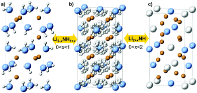
It is clear that the impressive performance of the M–N–H materials in these applications relates to compositional flexibility, which derives from the close structural relationships between the phases involved. Lithium amide and lithium imide both have crystal structures based on a cubic close packed arrangement of anions with occupancy of the tetrahedral holes by cations: the anti-fluorite structure. Lithium amide has a layered arrangement of lithium ions occupying half the holes, while in lithium imide these holes are fully occupied (Fig. 1a and b).
Structural similarities are also clear between lithium imide and lithium nitride–hydride (Li4NH, Fig. 1c). Here, nitride and hydride ions form an ordered arrangement based on the cubic close packed lattice, resulting in an a × a × 2a supercell of the anti-fluorite structure; the charge imbalance between nitride (3−) and hydride (1−) displaces the lithium ions from the tetrahedral site towards a trigonal coordination. As such, lithium nitride–hydride could also be described as an anti-scheelite structure, which is an ordered variant of the anti-fluorite structure. This close structural relationship between anti-fluorite and anti-scheelite suggests that mixed lithium imide–nitride–hydride phases (Li2+x(NH)1−xNxHx or Li2+xNH, 0 < x < 2) can be formed. This possibility was first reported by Marx, but without accompanying experimental data.23 However, evidence for the existence of such phases has been published in the context of hydrogen storage, where a cubic phase termed “quasi imide” was reported in neutron powder diffraction studies of the low-pressure hydrogenation of lithium nitride.24–26 The presence of imide–nitride–hydride was also proposed as an explanation for the ammonia decomposition activity of lithium imide, given the formation and subsequent ammoniation of lithium nitride–hydride within the imide structure is a possible ammonia decomposition cycle:19
| 2Li2NH → Li4NH + 1/2H2 + 1/2N2 | (2) |
| Li4NH + NH3 → 2Li2NH + H2 | (3) |
Experimental
Sample handling
All sample handling was performed in an argon-filled glove box (MBraun Unilab, O2 < 0.1 ppm, H2O < 0.1 ppm) because of the water sensitivity of the samples.Synthesis of lithium amide–imide (Li2−xNH1+x) samples
13 samples of Li2−xNH1+x (where x = 0, 0.083, 0.167, 0.250, 0.333, 0.417, 0.500, 0.583, 0.667, 0.750, 0.833, 0.917, 1.000) were synthesised by the reaction of lithium amide (LiNH2, Sigma Aldrich, 95%) with lithium nitride (Li3N, Sigma Aldrich, >99.5%) or lithium hydride (LiH, Sigma Aldrich, 95%) according to the following reactions:| (1 − x)Li3N + (1 + x)LiNH2 → 2Li2−xNH1+x | (4) |
| (1 − x)LiH + LiNH2 → Li2−xNH1+x + (1 − x)H2 | (5) |
The nitride-based method was the most reliable in producing samples of the desired stoichiometry; the hydride reaction was found to be more likely to show incomplete reaction, as evidenced by lack of formation of the low-temperature (Fd![[3 with combining macron]](https://www.rsc.org/images/entities/char_0033_0304.gif) m) lithium imide phase for the x = 0 sample (Fig. S1, ESI†). While the data discussed in the main text are from the nitride samples, very similar results were observed for the hydride samples (Fig. S1–S4, ESI†).
m) lithium imide phase for the x = 0 sample (Fig. S1, ESI†). While the data discussed in the main text are from the nitride samples, very similar results were observed for the hydride samples (Fig. S1–S4, ESI†).
The reagents were weighed out according to the desired ratio, with a total sample mass of 1 g. The samples were hand-ground using an agate mortar and pestle for approximately five minutes to ensure adequate mixing, and then transferred into a tungsten carbide milling jar (volume = 125 mL). Tungsten carbide milling balls (3 mm diameter) were added to achieve a 40![[thin space (1/6-em)]](https://www.rsc.org/images/entities/char_2009.gif) :
:![[thin space (1/6-em)]](https://www.rsc.org/images/entities/char_2009.gif) 1 mass ratio with the powder. The jar was then sealed and transferred into a planetary ball mill (Retsch PM100) and milled for 1 hour at 150 rpm, with the direction of rotation reversed at 10 minutes intervals.
1 mass ratio with the powder. The jar was then sealed and transferred into a planetary ball mill (Retsch PM100) and milled for 1 hour at 150 rpm, with the direction of rotation reversed at 10 minutes intervals.
0.5 g of the resultant mixture was transferred into a cylindrical alumina crucible and placed in the bottom of a glass boiling tube fitted with a Young's tap T-piece to prevent air ingress. The sample was then heated in a tube furnace (Lenton LTF12/38/500) under a continuous flow of argon to 300 °C at a heating rate of 2 °C min−1, and then dwelled at that temperature for 12 hours.
Synthesis of lithium imide–nitride–hydride (Li2+xNH) samples
13 samples of Li2+xNH (where x = 0, 0.167, 0.333, 0.500, 0.667, 0.833, 1.000, 1.167, 1.333, 1.500, 1.667, 1.833, 2.000) were synthesised by the solid state reaction of lithium imide with lithium nitride–hydride according to the following reaction:| (2 − x)Li2NH + xLi4NH → 2Li2+xNH | (6) |
Lithium imide for the reaction was synthesised as for the Li1+xNH2−x samples (x = 1.000). Lithium nitride–hydride was synthesised by the reaction of lithium hydride (Sigma Aldrich, 95%) and lithium nitride (Sigma Aldrich, >99.5%):
| LiH + Li3N → Li4NH | (7) |
Synthesis of the mixed Li2+xNH samples from lithium imide and lithium nitride–hydride was the same as for the other samples, except that the milling procedure used a rotation rate of 400 rpm, and the furnace temperature set point was 540 °C.
X-Ray diffraction
Structural analysis of the sample was performed using synchrotron X-ray diffraction; data were collected on the I11 high-resolution powder diffraction beamline (λ = 0.826021 Å) at the Diamond Light Source.27 Powder samples were loaded into 0.7 mm borosilicate glass capillaries, which were flame sealed. The samples were mounted onto the diffractometer using a robotic arm, and rotated while diffraction data (8–20 minutes scans) were collected using the five Multi-Analyser Crystal (MAC) detectors.All XRD data were analysed (generally by Rietveld analysis) using the TOPAS Academic package (v6).28
Raman spectroscopy
Spectroscopic analysis of the samples was performed using a Raman microscope (Bruker Senterra). Each sample was loaded into a 0.7 mm wide borosilicate glass capillary to a height of approximately 10 mm and sealed with grease. Each capillary was then individually loaded onto the adjustable table, moved into position and brought into focus using the built-in microscope with ×10 lens. Raman data were collected using a 20 mW, 532 nm laser, with an aperture of 50 × 1000 μm to ensure sampling across multiple powder grains. Peak areas and positions were analysed using the TOPAS Academic package.Thermal analysis
The thermal behaviour of the samples was analysed by differential scanning calorimetry (DSC), with experiments run on a Mettler Toledo DSC 1 instrument. 10 mg of powdered sample was loaded into a 20 μL aluminium pan and sealed with an aluminium lid in the glove box. After loading onto a carousel, a robotic arm individually loaded each sample into an inert atmosphere, pierced the lid and started the heating cycle. For amide–imide samples, each sample was heated to 450 °C from 25 °C at a rate of 5 °C min−1, then immediately cooled back to 25 °C at a rate of 10 °C min−1. Each imide–nitride–hydride sample was heated to 575 °C at a rate of 10 °C min−1, dwelled for 10 minutes and cooled back down to 100 °C. A flowing argon atmosphere (50 cm3 min−1) was used throughout each experiment.The reactivity of the lithium imide–nitride–hydride samples when heated under ammonia was studied in a simultaneous thermal analysis (STA) apparatus (Netzsch F1 Jupiter). Each sample was loaded into a 20 μL aluminium pan, sealed with an aluminium lid and pierced before loading to allow gas exchange. The samples were heated to 350 °C under ammonia at a rate of 5 °C min−1, dwelled at temperature for 5 hours and cooled back down to room temperature. The instrument was then purged with inert gas to remove the sample safely.
Results and discussion
Structural analysis: average structure
Synchrotron powder X-ray diffraction data provides a basis for assessment of the structural variation across the Li–N–H samples and the successful formation of solid solutions. These data are shown in Fig. 2. Lithium imide, shown in the central pattern in Fig. 2, is observed to form the low-temperature Fd![[3 with combining macron]](https://www.rsc.org/images/entities/char_0033_0304.gif) m structure which is a 2 × 2 × 2 supercell of the antifluorite structure, formed as a result of ordered N–H bond orientations facilitated by the formation of a Frenkel defect by 1/8 of the lithium ions. This structure is most obviously evidenced by presence of the (111) peak at around 8°. It can be seen that this ordered structure is specific to samples very close to Li2NH stoichiometry; the peak is not observed for any of the imide–nitride–hydride samples, and in the Li1.917NH1.083 amide–imide sample, it is present as a weak and broad feature, indicative of a coherence length of around 300 Å.
m structure which is a 2 × 2 × 2 supercell of the antifluorite structure, formed as a result of ordered N–H bond orientations facilitated by the formation of a Frenkel defect by 1/8 of the lithium ions. This structure is most obviously evidenced by presence of the (111) peak at around 8°. It can be seen that this ordered structure is specific to samples very close to Li2NH stoichiometry; the peak is not observed for any of the imide–nitride–hydride samples, and in the Li1.917NH1.083 amide–imide sample, it is present as a weak and broad feature, indicative of a coherence length of around 300 Å.
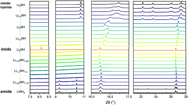 | ||
Fig. 2 Sections of synchrotron powder X-ray diffraction data for the Li–N–H samples. The first two panels show the superlattice regions where peaks for tetragonal lithium amide (9–10.5°) or lithium nitride–hydride (11°) and Fd![[3 with combining macron]](https://www.rsc.org/images/entities/char_0033_0304.gif) m lithium imide (8°) are expected. The third panel shows the peak region for (111)/(112) reflections of the cubic/tetragonal phases. The fourth panel shows a broader region highlighting the tetragonal peaks present for lithium amide and lithium nitride–hydride. Full diffraction patterns with Rietveld analysis are available in Fig. S5–S29 (ESI†). m lithium imide (8°) are expected. The third panel shows the peak region for (111)/(112) reflections of the cubic/tetragonal phases. The fourth panel shows a broader region highlighting the tetragonal peaks present for lithium amide and lithium nitride–hydride. Full diffraction patterns with Rietveld analysis are available in Fig. S5–S29 (ESI†). | ||
On either side of the stoichiometric imide, there is a wide compositional range where the diffraction data show only Fm![[3 with combining macron]](https://www.rsc.org/images/entities/char_0033_0304.gif) m peaks, indicating a disordered (solid solution) average structure. The amide–imide samples show a single well-defined phase up to Li1.333NH1.667 (x = 0.667), two-thirds substitution of amide within the structure. A similar trend was observed for amide–imide samples synthesised via the lithium amide lithium hydride reaction. This reflects an improved synthesis protocol over previous attempts to synthesise amide–imide phases, where a single phase was only observed29 up to x = 0.4. For imide–nitride–hydride samples, an Fm
m peaks, indicating a disordered (solid solution) average structure. The amide–imide samples show a single well-defined phase up to Li1.333NH1.667 (x = 0.667), two-thirds substitution of amide within the structure. A similar trend was observed for amide–imide samples synthesised via the lithium amide lithium hydride reaction. This reflects an improved synthesis protocol over previous attempts to synthesise amide–imide phases, where a single phase was only observed29 up to x = 0.4. For imide–nitride–hydride samples, an Fm![[3 with combining macron]](https://www.rsc.org/images/entities/char_0033_0304.gif) m structure is observed up to Li3.167NH (x = 1.167). These samples displayed much more complex microstructure than the amide–imide samples, with asymmetric peak shapes that are likely to be indicative of regions of variable composition. This likely reflects the higher enthalpic barriers to ion migration in the nitride–hydride–imide array compared with the amide–imide, where a lower-energy proton exchange and lithium ion migration is required. Grinding and re-heating these samples did not improve the peak symmetry. While the use of higher temperatures to synthesise those samples risks thermal degradation (and therefore loss of compositional control), further optimisation of milling routines may yet yield more uniform solid solutions. The data in the imide–nitride–hydride samples were modelled with a series of solid solution Fm
m structure is observed up to Li3.167NH (x = 1.167). These samples displayed much more complex microstructure than the amide–imide samples, with asymmetric peak shapes that are likely to be indicative of regions of variable composition. This likely reflects the higher enthalpic barriers to ion migration in the nitride–hydride–imide array compared with the amide–imide, where a lower-energy proton exchange and lithium ion migration is required. Grinding and re-heating these samples did not improve the peak symmetry. While the use of higher temperatures to synthesise those samples risks thermal degradation (and therefore loss of compositional control), further optimisation of milling routines may yet yield more uniform solid solutions. The data in the imide–nitride–hydride samples were modelled with a series of solid solution Fm![[3 with combining macron]](https://www.rsc.org/images/entities/char_0033_0304.gif) m phases with a constrained lattice parameter – composition relationship in the Rietveld analysis (ESI,† Section S3), while only one such phase was required to fit the amide–imide samples. The resultant phase compositions are shown in Fig. 3.
m phases with a constrained lattice parameter – composition relationship in the Rietveld analysis (ESI,† Section S3), while only one such phase was required to fit the amide–imide samples. The resultant phase compositions are shown in Fig. 3.
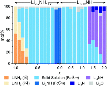 | ||
| Fig. 3 Phase composition as determined by Rietveld analysis of synchrotron powder X-ray diffraction data. | ||
Moving outside of the region where a full solid solution is formed, tetragonal lithium amide and lithium nitride–hydride phases are observed, with diminishing proportions of the cubic solid solution phases. In the amide-rich samples, additional diffraction peaks were observed in the superlattice region: peaks at 9.28° and 9.4° in addition to the (002) peak of I![[4 with combining macron]](https://www.rsc.org/images/entities/char_0034_0304.gif) lithium amide at 9.24°. These peaks were indexed to a P
lithium amide at 9.24°. These peaks were indexed to a P![[4 with combining macron]](https://www.rsc.org/images/entities/char_0034_0304.gif) structure (details in Table S1, ESI†) with very similar lattice parameters to lithium amide; consequently the data were modelled with a mixture of I
structure (details in Table S1, ESI†) with very similar lattice parameters to lithium amide; consequently the data were modelled with a mixture of I![[4 with combining macron]](https://www.rsc.org/images/entities/char_0034_0304.gif) and P
and P![[4 with combining macron]](https://www.rsc.org/images/entities/char_0034_0304.gif) lithium amide.
lithium amide.
The loss of body-centring implied by the P![[4 with combining macron]](https://www.rsc.org/images/entities/char_0034_0304.gif) phase is most likely related to a change in the lithium occupancy in the layered structure. The I
phase is most likely related to a change in the lithium occupancy in the layered structure. The I![[4 with combining macron]](https://www.rsc.org/images/entities/char_0034_0304.gif) structure has an alternating 0.25/0.75 occupancy of the tetrahedral sites in layers along the c-axis. Refinement of the crystallographically unique lithium sites in the P
structure has an alternating 0.25/0.75 occupancy of the tetrahedral sites in layers along the c-axis. Refinement of the crystallographically unique lithium sites in the P![[4 with combining macron]](https://www.rsc.org/images/entities/char_0034_0304.gif) structure indicates a disruption of that ordering (Table 1). The precise nature of the disordering is unclear, as the proportion of the P
structure indicates a disruption of that ordering (Table 1). The precise nature of the disordering is unclear, as the proportion of the P![[4 with combining macron]](https://www.rsc.org/images/entities/char_0034_0304.gif) phase is not sensitive to the overall sample stoichiometry, and the refined stoichiometry (Li0.96(6)NH2.04(6)) is not significantly different from lithium amide. It is likely that this phase represents a kinetically stabilised phase, perhaps as a result of the synthesis procedure; further examination of its thermal stability may confirm this.
phase is not sensitive to the overall sample stoichiometry, and the refined stoichiometry (Li0.96(6)NH2.04(6)) is not significantly different from lithium amide. It is likely that this phase represents a kinetically stabilised phase, perhaps as a result of the synthesis procedure; further examination of its thermal stability may confirm this.
![[4 with combining macron]](https://www.rsc.org/images/entities/char_0034_0304.gif) and P
and P![[4 with combining macron]](https://www.rsc.org/images/entities/char_0034_0304.gif) lithium amide. The resultant average stoichiometry of the phase is also shown
lithium amide. The resultant average stoichiometry of the phase is also shown
| Li layer fractional occupancy | ||
|---|---|---|
| c axis position |
I![[4 with combining macron]](https://www.rsc.org/images/entities/char_0034_0304.gif) |
P![[4 with combining macron]](https://www.rsc.org/images/entities/char_0034_0304.gif) |
| 0.75 | 0.250 | 0.32(7) |
| 0.50 | 0.750 | 0.6(1) |
| 0.25 | 0.250 | 0.32(7) |
| 0.00 | 0.750 | 0.7(1) |
| Stoichiometry | LiNH2 | Li0.96(7)NH2.04(7) |
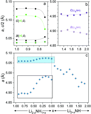
In order to gain insight into the nature of the compositional variation across the samples, lattice parameter data for the different phases are shown in Fig. 4. The lattice parameter value reported for the Fm![[3 with combining macron]](https://www.rsc.org/images/entities/char_0033_0304.gif) m phase in the imide–nitride–hydride samples is a weighted average of the three lattice parameters of the fitted phases.
m phase in the imide–nitride–hydride samples is a weighted average of the three lattice parameters of the fitted phases.
The lithium amide lattice parameters (Fig. 4a) are stable for 0.833 ≤ x ≤ 1, but show a drop in c/a for the x = 0.750 sample, which may reflect some compositional variation within the tetragonal structures. Conversely, the lithium nitride–hydride structure shows a steady drop in c/a as the composition moves away from stoichiometric Li4NH, which is likely to be associated with partial site disordering with imide incorporation. Indeed, initial reports of the structure of lithium nitride–hydride via powder diffraction measurements refined ∼5% anion site disorder,23 while single crystal diffraction data indicated a perfectly ordered structure.30
The lattice parameter of the Fm![[3 with combining macron]](https://www.rsc.org/images/entities/char_0033_0304.gif) m phase in the amide–imide samples displays an apparent minimum at x = 0.667 (Li1.333NH1.667), consistent with a maximum level of amide incorporation in the solid solution phase; further amide remains in the tetragonal structure. Between x = 0.583 and x = 0.333 the lattice parameter change is approximately linear before tailing off to a maximum at x = 0.167 and decreasing for Li1.917NH1.083 and Li2NH. This would appear to reflect the imide proportion at which onset of the ordered imide structure occurs, which relies on the ability to form lithium vacancies that are tetrahedrally coordinated by four imide groups.31,32
m phase in the amide–imide samples displays an apparent minimum at x = 0.667 (Li1.333NH1.667), consistent with a maximum level of amide incorporation in the solid solution phase; further amide remains in the tetragonal structure. Between x = 0.583 and x = 0.333 the lattice parameter change is approximately linear before tailing off to a maximum at x = 0.167 and decreasing for Li1.917NH1.083 and Li2NH. This would appear to reflect the imide proportion at which onset of the ordered imide structure occurs, which relies on the ability to form lithium vacancies that are tetrahedrally coordinated by four imide groups.31,32
The lattice parameter trend for the imide–nitride–hydride samples is more complex. A small proportion of nitride–hydride incorporation produces a more substantial response in the solid solution lattice parameter given the larger lattice mismatch for Li2NH/Li4NH than Li2NH/LiNH2. The lattice parameter of Li3NH appears to break the monotonous trend in the lattice parameter; this may reflect local ordering of the anions given the equal quantities of NH2− and (N3− + H−) at this composition, though no evidence of long-range ordering was observed. Additionally, the lattice parameter does not simply level off after x = 1.167, whereupon further increasing the proportion of nitride–hydride results in tetragonal lithium nitride–hydride formation. Instead, it continues to decrease, implying a continuing change in composition, though possibly at a less rapid rate, which would imply a reduced nitride–hydride component compared to the overall stoichiometry of the sample. It is also clear from an examination of the diffraction data that the microstructure of the solid solution phase and lithium nitride–hydride in these samples differs from the other imide–nitride–hydride mixtures. The Bragg peaks of both phases are significantly strain-broadened. One possible interpretation of these data is that a solid solution is possible across the whole compositional range, but that in these samples, the solid solution is only stable at elevated temperatures, and that rapid separation upon cooling leads to two highly strained, inhomogeneous phases. This possibility will be discussed further in relation to the thermal analysis of the samples.
Spectroscopic analysis
Raman spectroscopy was used in order to provide an insight into the local environments of the NHx groups in the samples, with the spectra shown in Fig. 5. The key features of the stoichiometric compounds are: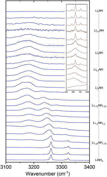 | ||
| Fig. 5 The N–H stretching region of the Raman spectra of the Li–N–H samples, and inset, the low-energy region of the imide–nitride–hydride samples. | ||
LiNH2 – symmetric NH2 stretch at 3262 cm−1, asymmetric NH2 stretches at 3314 and 3324 cm−1.
Li2NH – broad NH stretch at 3180 cm−1.
Li4NH – sharp phonon modes at 452, 584 and 775 cm−1.
Analysis of the Raman spectra of the amide–imide samples is based on a similar approach to that previously reported:29 the tetragonal lithium amide gives sharp NH2 stretch signals which remain at constant wavenumber, reflecting the compositional stability of the phase. A second set of broadened amide stretch peaks can be observed which represent amide ions in solid solution; these are the only amide peaks present from Li1.333NH1.667 onwards, reflecting the observations from the XRD data. These peaks, and the imide peak, can be observed to move to lower wavenumber as the solid solution becomes more imide-like and the average coordination number of lithium ions around each NHx group increases (peak areas and positions are given in the Fig. S31 and S32, ESI†). These data indicate the formation of a well-mixed solid solution.
In the case of imide–nitride–hydride samples, this trend is much less clear, given that the lithium occupancy does not vary across these samples. On the whole, the width of the imide stretch peak is larger when compared with the amide–imide samples, which likely reflects a wider compositional range in these samples, which is consistent with the peak shapes in the X-ray diffraction data. The lithium nitride–hydride peaks are well-defined in the samples which contain tetragonal lithium nitride, and generally much broader in the solid–solution samples.
Thermal analysis
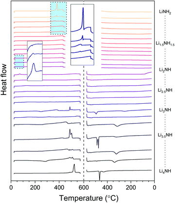
The thermal stability of the solid solutions is critical to determining the applications to which they might be best suited. In order to assess this, the samples were analysed by differential scanning calorimetry, with the data showing both heating and cooling cycles in Fig. 6. The amide–imide samples were tested between 25 °C and 450 °C, given the known decomposition of lithium amide to lithium imide around 400 °C, while the imide–nitride–hydride samples were tested up to 575 °C, given the decomposition of lithium imide to lithium nitride hydride above 600 °C.The melting of lithium amide is seen as a sharp endotherm at 370 °C, just prior to the onset of decomposition to lithium imide (shown in the larger inset box in Fig. 6). This melt transition is rapidly suppressed upon introduction of lithium imide, and is only visible at all for the samples which contain a detectable proportion of tetragonal lithium amide (LiNH2 to Li1.333NH1.667). All the remaining amide–imide solid solutions display no significant thermal events on heating or cooling, aside from the Fd![[3 with combining macron]](https://www.rsc.org/images/entities/char_0033_0304.gif) m to Fm
m to Fm![[3 with combining macron]](https://www.rsc.org/images/entities/char_0033_0304.gif) m phase transition in Li1.913NH1.083 and Li2NH at 60 °C, highlighted in the small inset box in Fig. 6. This trend continues for the imide–nitride–hydride samples for which only Fm
m phase transition in Li1.913NH1.083 and Li2NH at 60 °C, highlighted in the small inset box in Fig. 6. This trend continues for the imide–nitride–hydride samples for which only Fm![[3 with combining macron]](https://www.rsc.org/images/entities/char_0033_0304.gif) m phases were observed (Li2NH to Li3.167NH aside from Li3NH).
m phases were observed (Li2NH to Li3.167NH aside from Li3NH).
For the samples which had both solid solution and tetragonal Li4NH phases present in the diffraction data, the thermal behavior is more complex. Endothermic events at 489 °C can be seen in these samples, followed by a second endotherm from 505–510 °C. A tetragonal to cubic phase transition for Li4NH has previously been reported at 497 °C,33 and so we hypothesise that these two endotherms may be this phase transition followed by formation of a single imide–nitride–hydride phase. Interestingly, the endotherm for Li4NH is at significantly higher temperature (525 °C), though has a large hysteresis, with the corresponding exotherm on cooling observed at 465 °C. The Li3NH and Li3.5NH samples also display exotherms in this region, perhaps indicating incomplete mixing of imide and nitride–hydride. For the other samples in this compositional range, a broad exotherm is observed in the 315–340 °C range. It is probable that this feature corresponds to phase segregation of the high temperature solid solution into the Fm![[3 with combining macron]](https://www.rsc.org/images/entities/char_0033_0304.gif) m and tetragonal Li4NH phases observed in the diffraction data. This is consistent with the observed broadened Bragg peaks for these phases as discussed earlier.
m and tetragonal Li4NH phases observed in the diffraction data. This is consistent with the observed broadened Bragg peaks for these phases as discussed earlier.
Implications for hydrogen storage and catalysis
The Li–N–H solid solution demonstrates remarkable tolerance for compositional variation, with samples successfully synthesised for the composition range Li1.333NH1.667 to Li3.167NH, and indications of wider stability for nitride–hydride rich samples above 500 °C. A summary of the stable composition range and some of the local structural features which characterise different regions of the solid solution are given in Fig. 7. The structural and thermal stability data collected for these samples provide some useful insights into the properties of the solid solution, which may impact use of the material in hydrogen storage and catalysis applications.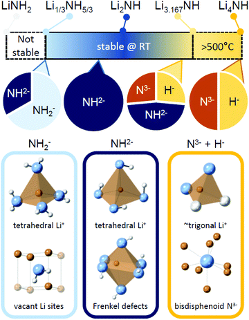 | ||
| Fig. 7 A summary of the stable composition range of the Li–N–H solid solution, along with key structural features expected for samples dominate by amide, imide or nitride–hydride anions. | ||
In the field of hydrogen storage, the reversibility of the hydrogen storage process has been attributed to solid solution formation. This process is facilitated by Li+ and H+ diffusion through the structure.8,34 However, the temperature for reversible hydrogen storage is still significantly higher than could be achieved using waste heat from a PEM fuel cell, reducing overall efficiency. Given the tetragonal amide structure is known to be a very poor Li+ conductor (∼10−10 S cm−1 at room temperature35), it might be expected that the hydrogen storage properties would be improved by keeping the system within the more conductive lithium imide structure (Li2NH has been reported to have a room temperature conductivity of around 3 × 10⁻⁴ S cm−1![[thin space (1/6-em)]](https://www.rsc.org/images/entities/char_2009.gif) 35,36). Having revealed an apparent upper limit to amide content of the solid solution at Li1.333NH1.667, it may be possible to achieve a more favourable operating temperature by restricting the hydrogenation capacity to two thirds of the theoretical maximum.
35,36). Having revealed an apparent upper limit to amide content of the solid solution at Li1.333NH1.667, it may be possible to achieve a more favourable operating temperature by restricting the hydrogenation capacity to two thirds of the theoretical maximum.
Loss of the tetragonal structure is also important to the deployment of lithium amide–imide catalysts for ammonia decomposition, where loss of catalyst material through melting will degrade activity over time and also thwart attempts to create high surface area formulations to maximise turnover frequency. In our recent demonstration of a lithium imide ammonia cracking unit coupled to a PEM fuel cell, a Dreschel bottle style reactor was used to avoid blocking of the reactor in case of catalyst melting.37 It would be preferable to use a packed bed reactor in order to maximise the exposure of ammonia to the catalyst surface. While the precise stoichiometry has been shown to vary under the reaction conditions chosen, it is clear that maintaining a more imide-like stoichiometry than Li1.33NH1.667 will prevent melting of the sample.
The demonstrated ability of the anti-fluorite Li–N–H structure to accommodate a wide variety of ions also has implications for understanding its role in catalysis. Certainly, the existence of a wide range of stable imide–nitride–hydride solid solutions supports the possibility that nitride–hydride formation could play a role in the catalytic decomposition of ammonia by lithium imide. Additionally, the accommodation of H+, H−, N3−, NH2− and NH2− within the structure suggests that these phases could play an analogous role to that ascribed to the Ca–N–H supports for ruthenium based ammonia synthesis catalysts, acting as a reservoir of reactive species which might otherwise occupy surface sites on the metal catalyst. Similarly, an analogy may be drawn to the metal nitride catalysts such as Co3Mo3N and Li–Mn–N phases, where the proposed Mars–van Krevelen mechanism involves reactivity of the lattice nitrogen in ammonia synthesis.38–40 The bulk transport of ions within the solid may also help explain the effectiveness of the materials as catalysts/supports despite generally low surface areas. Previous work has demonstrated that bulk nitrogen/hydrogen exchange is possible with ammonia, but these solid solutions also react with hydrogen, and lithium nitride–hydride is also able to fix nitrogen.23,33 Thus these phases show promise not only as catalysts in their own right, but also as components of composite catalyst formulations, where multi-site approaches are increasingly seen as the most promising way to escape the bottleneck of energy scaling relations on single-site catalyst surfaces.41–43
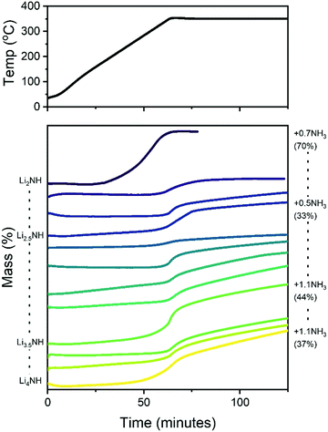
It is therefore of significant interest the extent to which these compositional modifications perturb the electronic structure and reactivity of the materials. An initial demonstration of such variation is shown in Fig. 8, which details the results of STA experiments for the imide–nitride–hydride samples, heated under flowing ammonia. All of the samples would be expected to react to form lithium amide, by absorption of between one (for Li2NH) and three (for Li4NH) equivalents of ammonia. Indeed, mass uptake is observed. However, it is clear that even very minor incorporation of nitride–hydride into the solid solution leads to a dramatic change in the absorption profile, which more strongly resembles that of lithium nitride–hydride. The onset of rapid ammonia reaction was shifted by more than 100 °C and a generally slower kinetic profile can be seen, evidenced by the significantly reduced extent of reaction of the nitride–hydride containing samples over the duration of the experiment. Imide to amide conversion is likely to be facilitated by Grotthuss-style proton transfer through the solid, while conversion of nitride–hydride appears to be more kinetically hindered. These results are not inconsistent with the hypothesised stabilisation of nitride–hydride regions in lithium imide under ammonia decomposition conditions.19 A more comprehensive assessment of reactivity–composition relationship, including under catalytic conditions, is now possible with this library of compounds. As illustrated in Fig. 7, changing anion compositions will bring particular defect/vacancy/coordination features which could be targeted for particular applications.
Conclusions
Through the synthesis of mixtures of lithium amide, lithium imide and lithium nitride–hydride, a solid solution with wide-ranging anion composition has been revealed. A highly disordered, anti-fluorite structure was observed for samples from majority lithium amide through to pure lithium imide and majority lithium nitride–hydride, with evidence for greater nitride–hydride incorporation at high temperatures. In contrast, the tetragonal lithium amide and nitride–hydride structures were found to show only limited evidence of compositional variation.While imide–nitride–hydride solid solution formation is somewhat kinetically hindered, Raman spectroscopy of amide–imide samples was found to show monotonic variation in the local NHx environment. Further work focused on other structural and spectroscopic probes of the local structure, along with computational investigations, will be able to provide further insight as to the relationship between local structural features in solid solutions and the parent phases.
The formation of solid solutions has been related to a number of key functional properties of the materials, from a composition range for maintaining the more highly-conductive cubic structure for optimising hydrogen storage characteristics, to broadening the thermal stability of the material, and demonstrating significant changes in the reactivity of lithium imide with ammonia upon small amounts of nitride–hydride incorporation. With the ability to select the desired anion mixture and its related vacancy and defect phenomena, the Li–N–H system now represents a rich library of candidates for materials applications in catalysis and energy storage, and a basis for expanded investigations into composition control in M–N–H materials.
Author contributions
Conceptualisation: JWM, WIFD and TJW. Investigation: JMB, ASM, JWM, TJW and CAM. Formal analysis: JMB, ASM, JWM, TJW and WIFD. Software: TJW. Writing – original draft: JWM, JMB, ASM. Writing – review and editing: all authors.Conflicts of interest
There are no conflicts of interest to declare.Acknowledgements
The authors thank Dr James Taylor for technical laboratory support and the Diamond Light Source for the provision of experimental time on I11 (EE14926-1). JWM would like to acknowledge UKRI Future Leaders Fellowship funding from MRC (MR/S03403X/1), St John's College Oxford (Junior Research Fellowship) and the University of Oxford (John Fell Fund). Crystal structure graphics were generated using CrystalMaker X.References
- P. Chen, Z. Xiong, J. Luo, J. Lin and K. L. Tan, Interaction of hydrogen with metal nitrides and imides, Nature, 2002, 420, 302–304 CrossRef CAS PubMed.
- D. H. Gregory, Lithium nitrides, imides and amides as lightweight, reversible hydrogen stores, J. Mater. Chem., 2008, 18, 2321–2330 RSC.
- W. Grochala and P. P. Edwards, Thermal decomposition of the non-interstitial hydrides for the storage and production of hydrogen, Chem. Rev., 2004, 104, 1283–1316 CrossRef CAS PubMed.
- L. Schlapbach and A. Züttel, Hydrogen storage for mobile applications, Nature, 2001, 414, 353–358 CrossRef CAS PubMed.
- M. Hirscher, et al., Materials for hydrogen-based energy storage – past, recent progress and future outlook, J. Alloys Compd., 2020, 827, 153548 CrossRef CAS.
- W. Osborn, T. Markmaitree and L. L. Shaw, The long-term hydriding and dehydriding stability of the nanoscale LiNH2 + LiH hydrogen storage system, Nanotechnology, 2009, 20, 204028 CrossRef PubMed.
- W. I. F. David, Effective hydrogen storage: a strategic chemistry challenge, Faraday Discuss., 2011, 151, 399–414 RSC.
- W. I. F. David, et al., A mechanism for non-stoichiometry in the lithium amide/lithium imide hydrogen storage reaction, J. Am. Chem. Soc., 2007, 129, 1594–1601 CrossRef CAS PubMed.
- J. W. Makepeace, M. O. Jones, S. K. Callear, P. P. Edwards and W. I. F. David, In situ X-ray powder diffraction studies of hydrogen storage and release in the Li-N-H system, Phys. Chem. Chem. Phys., 2014, 16, 4061–4070 RSC.
- The Royal Society, Ammonia: Zero-carbon fuel and energy store, 2020 Search PubMed.
- R. F. Service, Liquid Sunshine, Science, 2018, 361, 120–123 CrossRef CAS PubMed.
- A. Valera-Medina, H. Xiao, M. Owen-Jones, W. I. F. David and P. J. Bowen, Ammonia for power, Prog. Energy Combust. Sci., 2018, 69, 63–102 CrossRef.
- R. Lan, J. T. S. Irvine and S. Tao, Ammonia and related chemicals as potential indirect hydrogen storage materials, Int. J. Hydrogen Energy, 2012, 37, 1482–1494 CrossRef CAS.
- J. W. Makepeace, et al., Reversible ammonia-based and liquid organic hydrogen carriers for high-density hydrogen storage: Recent progress, Int. J. Hydrogen Energy, 2019, 44, 7746–7767 CrossRef CAS.
- J. W. Makepeace, T. J. Wood, H. M. A. Hunter, M. O. Jones and W. I. F. David, Ammonia decomposition catalysis using non-stoichiometric lithium imide, Chem. Sci., 2015, 6, 3805–3815 RSC.
- J. Guo, et al., Lithium Imide Synergy with 3d Transition-Metal Nitrides Leading to Unprecedented Catalytic Activities for Ammonia Decomposition, Angew. Chem., Int. Ed., 2015, 127, 2993–2997 CrossRef.
- H. Cao, et al., Transition and Alkali Metal Complex Ternary Amides for Ammonia Synthesis and Decomposition, Chem. – Eur. J., 2017, 23, 9766–9771 CrossRef CAS PubMed.
- J. W. Makepeace, et al., Ammonia decomposition catalysis using lithium-calcium imide, Faraday Discuss., 2016, 188, 525–544 RSC.
- T. J. Wood, J. W. Makepeace and W. I. F. David, Isotopic studies of the ammonia decomposition reaction using lithium imide catalyst, Phys. Chem. Chem. Phys., 2017, 19, 4719–4724 RSC.
- Y. Inoue, et al., Efficient and Stable Ammonia Synthesis by Self-Organized Flat Ru Nanoparticles on Calcium Amide, ACS Catal., 2016, 6, 7577–7584 CrossRef CAS.
- M. Kitano, et al., Self-organized Ruthenium–Barium Core–Shell Nanoparticles on a Mesoporous Calcium Amide Matrix for Efficient Low-Temperature Ammonia Synthesis, Angew. Chem., Int. Ed., 2018, 57, 2648–2652 CrossRef CAS PubMed.
- M. Kitano, et al., Essential role of hydride ion in ruthenium-based ammonia synthesis catalysts, Chem. Sci., 2016, 7, 4036–4043 RSC.
- R. Marx, Preparation and Crystal Structure of Lithium Nitride Hydride, Li4NH, Li4ND, Z. Anorg. Allg. Chem., 1997, 623, 1912–1916 CrossRef CAS.
- D. J. Bull, et al., Pressure-dependent deuterium reaction pathways in the Li-N-D system, Phys. Chem. Chem. Phys., 2010, 12, 2089–2097 RSC.
- D. J. Bull, et al., In-situ powder neutron diffraction study of non-stoichiometric phase formation during the hydrogenation of Li3N, Faraday Discuss., 2011, 151, 263–270 RSC.
- E. Weidner, et al., Observation of novel phases during deuteration of lithium nitride from in situ neutron diffraction, Chem. Phys. Lett., 2007, 444, 76–79 CrossRef CAS.
- S. P. Thompson, et al., Beamline I11 at Diamond: a new instrument for high resolution powder diffraction, Rev. Sci. Instrum., 2009, 80, 075107 CrossRef CAS PubMed.
- A. Coelho, A bound constrained conjugate gradient solution method as applied to crystallographic refinement problems, J. Appl. Crystallogr., 2005, 38, 455–461 CrossRef CAS.
- J. W. Makepeace and W. I. F. David, Structural Insights into the Lithium Amide-Imide Solid Solution, J. Phys. Chem. C, 2017, 121, 12010–12017 CrossRef CAS.
- R. Niewa and D. A. Zherebtsov, Redetermination of the crystal structure of tetralithium mononitride monohydride, Li4NH, Z. Kristallogr., 2002, 217, 317–318 CAS.
- G. Miceli, M. Ceriotti, M. Bernasconi and M. Parrinello, Static disorder and structural correlations in the low-temperature phase of lithium imide, Phys. Rev. B: Condens. Matter Mater. Phys., 2011, 83, 054119 CrossRef.
- T. Mueller and G. Ceder, Ab initio study of the low-temperature phases of lithium imide, Phys. Rev. B: Condens. Matter Mater. Phys., 2010, 82, 174307 CrossRef.
- N. Tapia-Ruiz, N. Sorbie, N. Vaché, T. K. A. Hoang and D. H. Gregory, Rapid microwave synthesis, characterization and reactivity of lithium nitride hydride, Li4NH, Materials, 2013, 6, 5410–5426 CrossRef PubMed.
- G. Miceli, C. S. Cucinotta, M. Bernasconi and M. Parrinello, First Principles Study of the LiNH2/Li2NH Transformation, J. Phys. Chem. C, 2010, 114, 15174–15183 CrossRef CAS.
- W. Li, G. Wu, Z. Xiong, Y. P. Feng and P. Chen, Li+ ionic conductivities and diffusion mechanisms in Li-based imides and lithium amide, Phys. Chem. Chem. Phys., 2012, 14, 1596–1606 RSC.
- B. A. Boukamp and R. A. Huggins, Ionic conductivity in lithium imide, Phys. Lett., 1979, 72A, 464–466 CrossRef CAS.
- H. M. A. Hunter, et al., Demonstrating hydrogen production from ammonia using lithium imide – Powering a small proton exchange membrane fuel cell, J. Power Sources, 2016, 329, 138–147 CrossRef CAS.
- S. M. Hunter, D. H. Gregory, J. S. J. Hargreaves, D. Duprez and N. Bion, A Study of 15N/14N Isotopic Exchange over Cobalt Molybdenum Nitrides, ACS Catal., 2013, 3, 1719–1725 CrossRef CAS PubMed.
- C. D. Zeinalipour-Yazdi, J. S. J. Hargreaves and C. R. A. Catlow, Nitrogen Activation in a Mars-van Krevelen Mechanism for Ammonia Synthesis on Co3Mo3N, J. Phys. Chem. C, 2015, 119, 28368–28376 CrossRef CAS.
- S. Laassiri, C. D. Zeinalipour-Yazdi, C. R. A. Catlow and J. S. J. Hargreaves, The potential of manganese nitride based materials as nitrogen transfer reagents for nitrogen chemical looping, Appl. Catal., B, 2018, 223, 60–66 CrossRef CAS.
- T. N. Ye, et al., Vacancy-enabled N2 activation for ammonia synthesis on an Ni-loaded catalyst, Nature, 2020, 583, 391–395 CrossRef CAS PubMed.
- P. Wang, et al., Breaking scaling relations to achieve low-temperature ammonia synthesis through LiH-mediated nitrogen transfer and hydrogenation, Nat. Chem., 2016, 9, 64–70 CrossRef PubMed.
- A. J. Medford, et al., From the Sabatier principle to a predictive theory of transition-metal heterogeneous catalysis, J. Catal., 2015, 328, 36–42 CrossRef CAS.
Footnote |
| † Electronic supplementary information (ESI) available. See DOI: 10.1039/d1cp02440j |
| This journal is © the Owner Societies 2021 |


