pH-Responsive aggregation-induced emission of Au nanoclusters and crystallization of the Au(I)–thiolate shell†
Jianxing
Wang
a,
Nirmal
Goswami
b,
Tong
Shu
*a,
Lei
Su
 *a and
Xueji
Zhang
*a
aBeijing Advanced Innovation Center of Materials Genome Engineering, Beijing Key Laboratory for Bioengineering and Sensing Technology, Research Center for Bioengineering and Sensing Technology, University of Science and Technology Beijing, Beijing 100083, P. R. China. E-mail: shutong@ustb.edu.cn; sulei@ustb.edu.cn; zhangxueji@ustb.edu.cn
bDepartment of Chemical and Biomolecular Engineering, National University of Singapore, 10 Kent Ridge Crescent, Singapore 119260, Singapore
First published on 7th February 2018
Abstract
Aggregation-induced emission (AIE) is an attractive strategy for enhancing the luminescence of metal nanoclusters (NCs). However, rational control of the AIE of Au NCs is currently one of the key challenges and fundamental understanding of the complex surface/interfacial structures, and the emission mechanism of AIE-type Au NCs is far from complete. In this study, we report a pH-controllable AIE accompanied with a self-assembly/disassembly process of Au NCs with Au(I)–thiolate complexes with glutathione (GSH)-protected AIE-type Au NCs as a model. It was found that the solution pH could be used to control the landscape of the Au(I)–thiolate complexes encapsulating the Au NCs, generating varied AIE. Transmission electron microscopy (TEM) studies revealed that the Au NCs were essentially embedded inside the pH-sensitive supramolecular assemblies of the Au(I)–thiolate complexes. It was further found that a certain degree of crystallization of the Au(I)–thiolate shell occurred on the surface of the Au NCs. This study expands the knowledge of both the surface/interfacial structures of AIE-type metal NCs and the control of their PL and their self-assembly.
Introduction
Metal nanoclusters, typically consisting of a few metal atoms, could bridge small organometallic complexes and large metal nanoparticles (NPs). The size of metal NCs is comparable to the Fermi wavelength of electrons, and metal NCs often feature with intriguing molecular-like properties, such as photoluminescence (PL), HOMO–LUMO transitions, and molecular chirality. They have recently attracted increasing research interest in many optical fields, including biosensing, bioimaging, and solid-state lighting and display.1–9 However, the quantum yields (QYs) of metal NCs are often lower (e.g., <0.1%) than other luminescent materials,10,11 greatly limiting their practical applications. There is therefore a pressing need to develop efficient methods to enhance the luminescence of metal NCs.Among the newly developed enhancement approaches, AIE12,13 is an attractive strategy as it could help achieve desirable QYs of Au NCs in solution and the resultant advanced luminescent materials have promising application potential in many fields including optical fields14–23 and biomedical fields.24–28 AIE-type Au NCs are commonly believed to be formed from the controlled reduction of Au(I)–thiolate complexes to Au(0)-on-Au(I)–thiolate intermediates followed by slow aggregation to generate core–shell structures, each consisting of an Au(0) core and an Au(I)–thiolate complex shell.14 The shell has been considered to be compact and rigid, thereby facilitating to restrain intramolecular vibration- and rotation-induced internal nonradiative relaxation pathways.13,14 Nevertheless, it has less capability of controlling AIE of the AIE-type Au NCs. In addition, the fundamental understanding of the complex surface/interfacial structures and the emission mechanism of AIE-type Au NCs is far from complete.
Using GSH-protected AIE-type Au NCs as a model, here we report a pH-controllable AIE accompanied with a self-assembly/disassembly process of Au NCs with Au(I)–thiolate complexes. Interestingly, the pH-driven disassembly has led to the finding of the monodispersed Au NCs with a crystalline ligand shell, exhibiting enhanced luminescence with a QY of ∼14%. On the other hand, previous studies have reported that the aggregation of Au(I)–thiolate complexes on the Au core would enhance the luminescence of Au NCs. However, the detailed aggregation/assembly states of the Au(I)–thiolate complexes on the Au NC surface and the complex interfacial/surface structures of the Au NCs involved in AIE are not clear. Here we found that a certain degree of crystallization of the Au(I)–thiolate shell occurs on the surface of AIE-type Au NCs.
Results and discussion
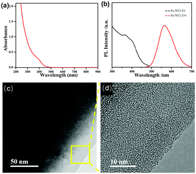
We first used UV-vis absorption and PL spectroscopy to characterize the as-synthesized AIE-type GSH-protected Au NCs. The UV-vis absorption spectrum of the Au NCs (Fig. 1a) shows a shoulder peak at about 400 nm. The PL spectrum of the Au NCs (Fig. 1b) shows a main peak at 565 nm and a shoulder peak at 610 nm, which is supportive for its orange emission under UV light. The QY of the Au NCs was determined to be ∼6% using fluorescein as a reference. This QY is much higher than other types of metal NCs, which generally have a QY below 0.1%.10 We further examined the oxidation states of Au in the as-synthesized AIE-type Au NCs using X-ray photoelectron spectroscopy (XPS). As shown in Fig. S1 (ESI†), the Au 4f spectrum can be deconvoluted into two peaks corresponding to Au(I) (84.3 eV) and Au(0) (83.7 eV), and the Au(I) content was determined to be ∼75% (on the basis of Au atoms). We tried to determine the structures of the Au NCs by mass spectrometry,29,30 but failed because of the challenge in obtaining good spectra and the uncertainty in fragmentation of the ligands. The obtained Au NC solution was clear and had an acidic pH value (∼2.0). It has been known that the polymeric Au(I) complexes can self-assemble into supramolecules in acidic aqueous solution.31,32 Dynamic light scattering (DLS) measurements were used to examine the Au NC solution. However, no good-quality DLS data could be obtained, perhaps there were lots of flexible assemblies or particles possessing varied sizes beyond the detection limit of the DLS apparatus. TEM was used to directly observe the as-synthesized AIE-type Au NCs. Yet only thick membranous substances could be seen, as shown in Fig. 1c. Even from the high-resolution TEM (HRTEM) image shown in Fig. 1d, the Au NCs are difficult to be identified due to the presence of the thick membranous substances which could encapsulate the clusters. The formation of these membranous substances suggests the presence of an excess of the Au(I)–thiolate complexes in the Au NC solution, in accordance with the presence of a high percentage of Au(I) in the Au NC solution as mentioned above. Also, this formation could be associated with the acid-induced aggregation property of Au(I)–thiolate complexes via the inter-chain stacked hydrogen bonding, Au(I)⋯Au(I) aurophilic and zwitterionic interactions.31,32 In addition, these membranous substances were not stable upon prolonged electron beam exposure in vacuum chambers and they easily volatilized, causing the membrane damage (Fig. S2, ESI†). This observation is consistent with previous reports that strong electron beam irradiation can burn off the organic ligands of metal NCs or NPs.33,34According to previous studies,31,32 increasing the pH could lead to the decomposition of the Au(I)–thiolate polymeric aggregates/supramolecules. Then, we tried to disaggregate these Au(I)–thiolate membranous substances by increasing the pH, but which could quench the PL of the Au NCs because it was reported that the strong PL of AIE-type Au NCs could just originate from aggregation/assembly-induced emission of the Au(I)–thiolate complexes. DLS was used to measure the pH-induced changes in the sizes of the Au NCs-embedded Au(I)–thiolate aggregates. It was found that DLS measurements could obtain effective data as the pH value was 5.0 and higher. As shown in Fig. 2a, it can be seen that increasing the solution pH could lead to the narrowing of the size distribution and the decrease in particle sizes, suggesting the pH-driven disassembly of the Au(I)–thiolate aggregates. On the other hand, unexpectedly, it was observed that upon increasing the solution pH the PL intensity of the Au NC solution became enhanced, as shown in Fig. 2b. The PL intensity at pH 11.0 was almost three times as that at pH 2.0, and Au NCs had a QY of ∼14%, which is much higher than that of the reported luminescent metal NCs.10 Moreover, by restoring the pH value from 11.0 to 2.0, the PL of the Au NCs could also be restored (Fig. S3, ESI†), indicating that such a process in response to the pH changes was reversible. The PL lifetime measurement was performed to understand the PL property of the Au NCs. The microsecond-scale lifetime (1.22 μs (61.91%) at pH 2.0 and 1.39 μs (69.08%) at pH 11.0, Fig. S4, ESI†) indicates that the main components of the measured PL originated from the triplet-centered states.13,14 At pH values higher than 11.0, however, the PL intensity decreased again. For instance, at pH 13.0, the luminescence of Au NCs was totally quenched, and its XPS spectrum only shows the presence of the Au(I) state, indicating the oxidative decomposition of the Au NCs (Fig. S5, ESI†).
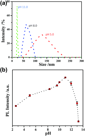 | ||
| Fig. 2 (a) DLS data of the Au NC solution. (b) The effect of pH on the PL intensity of the AIE-type Au NCs. | ||
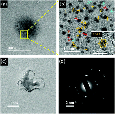
Furthermore, these pH-sensitive AIE-type Au NCs were studied by TEM. At pH 5.0, as shown in Fig. 3a, thick membranous substances almost disappeared, confirming the dissociation of them by increasing the pH. Accordingly, the Au NCs were visible in TEM. However, these Au NCs got together to form aggregates (Fig. 3a, the zone marked by yellow frame). The HRTEM image (Fig. 3b) suggests that these Au NCs had a particle size of 2.02 ± 0.6 nm (Fig. S6, ESI†). Interestingly, the lattice fringes of Au(I)–thiolate complexes could be clearly seen, indicating that the Au(I)–thiolate complexes were wrapped around the Au NCs, forming multi-layered crystalline regions. The polymeric crystalline regions close to the Au NCs have a lattice fringe spacing of 2.35 Å, and those crystalline structures further away from the Au NCs have a larger lattice fringe spacing of 3.00 Å. The HRTEM image of an individual Au NC (inset of Fig. 3b) further confirms that the Au NCs themselves were actually encapsulated by the organometallic crystalline polymers, and thus only the lattice fringes of the crystalline Au(I)–thiolate complexes could be clearly seen. These crystalline regions had very small dimensions and random orientations, in accordance with the features of crystalline polymers.35–37 Small amorphous regions could also be seen near the Au NCs.
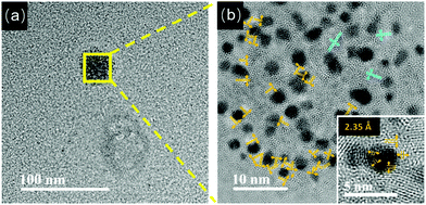 | ||
| Fig. 3 (a) TEM image of the Au NCs at pH 5.0. (b) HRTEM image of the zone marked by the yellow frame in (a). (inset) Enlarged HRTEM image of one Au NC in (b). | ||
At pH 8.0, large aggregates containing the Au NCs were still observed (Fig. 4a). The HRTEM image (Fig. 4b) shows the presence of polymeric crystalline regions between the Au NCs. The lattice fringes near the Au NCs and away from the Au NCs are 2.35 Å and 3.00 Å, respectively. In addition, there are some polymeric crystalline regions with a lattice fringe of 2.04 Å. Interestingly, as shown in the inset of Fig. 3d, the Au NCs look clearer, suggesting that the folded layers of the Au(I)–thiolate complexes encapsulating the Au NCs might become thin. On the Au NCs, it can be clearly seen that there are lattice fringes separated by 2.35 Å. Moreover, by taking a careful look at the lattice fringes shown on the Au NCs, one can see that these lattice fringes could extend beyond the gold cores, indicating that these lattice fringes on the Au NCs should have originated from the folded Au(I)–thiolate complexes. It is worth noting that the measured value, 2.35 Å, is identical to the (111) lattice spacing of the FCC gold. In previous studies, the lattice fringes of 2.35 Å for thiolate-protected Au NCs were attributed to the (111) lattice of the FCC gold.38 However, the origin of the 2.35 Å lattice fringe on thiolate-protected Au NCs is presently not clear.39 From our observations, it can be concluded that the lattice fringes appearing on the Au NCs could be attributed to the folded Au(I)–thiolate complexes. In addition, the presence of the Au NCs-embedded aggregates at pH 8.0 was further confirmed by using cryo-TEM that allows direct observation of particles or macromolecular assemblies in a near-native environment. As shown in Fig. 4c, aggregates larger than 50 nm were visible in cryo-TEM. SAED of the aggregates also showed complex spot patterns indicative of multiple crystallographic orientations (Fig. 4d). Therefore, the AIE-type Au NCs were essentially embedded inside the crystalline supramolecular assemblies of the Au(I)–thiolate complexes. However, it must be pointed out that the crystalline supramolecular assemblies of Au(I)–thiolate complexes embedding the Au NCs could have no positive contribution to the AIE of Au NCs, because the AIE became stronger (Fig. 2b) after disassembling them via further increasing the pH (vide infra).
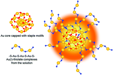
As the solution pH was increased to 11.0, the Au NC aggregates further disassembled (Fig. 5a, black spots). By magnifying the zone marked with the yellow frame in Fig. 5a, well-dispersed Au NCs with a mean size of 2.0 ± 0.8 nm (Fig. S7, ESI†) were visible (Fig. 5b). Unexpectedly and interestingly, the lattice fringes of the crystalline Au(I)–thiolated complexes can be clearly seen on the surfaces of these monodispersed Au NCs and are separated by 2.25 Å or 2.04 Å. It has been known that the highly repulsive force existed between GSH ligand molecules due to the dissociation of GSH ligand molecules under alkaline solution, thereby impeding the formation of supramoleculear structures.14,31,32 Thus, the fact of the survival of the crystalline Au(I)–thiolated complexes on the monodispersed Au NCs against so strong alkaline solution (pH 11.0) indicates that these crystalline Au(I)–thiolated complexes could interact strongly with the Au(I)–thiolate staple-like motifs of Au NCs, forming a stable structure. It is worth noting that at this pH value, as shown in Fig. 2b, the PL intensity was maximum with a QY of ∼14%, also indicating that intramolecular vibration- and rotation-induced internal nonradiative relaxation pathways were restrained due to the compactness and rigidness of the ligand shell of Au NCs.11,13,14 Moreover, it has been known that the outer shell of Au NCs might not form a closed shell: for instance, for Au25–thiolate clusters, eight more Au atoms would be needed to cap all the faces of their icosahedral cores.40 Therefore, it is rational that during the formation process of the AIE Au NCs, the Au(I)–thiolate complexes might have precious opportunities to insert their –SR ligands into the shell of the Au NCs to form strong aurophilic interactions between the Au(I) atoms of the staple-like motifs binding to the interior Au atoms and the Au(I) atoms of the Au(I)–thiolate complexes, forming crystalline and hence more compact and rigid shell, thereby contributing significantly to strong emission (Scheme 1). Further investigation is ongoing in our laboratory. In addition, by restoring the pH from 11.0 to 8.0, these Au NCs could be self-assembled again to form large aggregates, similar to those observed at pH 8.0, as revealed in Fig. S8 (ESI†).
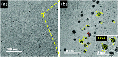 | ||
| Fig. 5 (a) TEM image of the Au NCs at pH 11.0. (b) HRTEM image of the zone marked by the yellow frame in (a). (inset) Enlarged HRTEM image of the Au NCs in (b). | ||
Experimental
Chemicals
Hydrogen tetrachloroaurate trihydrate (HAuCl4·3H2O), L-glutathione in the reduced form and L-cysteine were provided by Sigma-Aldrich. All other chemicals of at least analytical reagent were obtained from Beijing Chemical Corporation (Beijing, China). All chemicals were used without further purification. Ultrapure water prepared by a Millipore-Q system (≥18 MΩ, Milli-Q, Millipore) was used throughout the study.Synthesis and pH-driven self-assembly/disassembly of the GSH-capped Au NCs
The synthesis of the Au NCs was done according to a procedure14 described previously with some modifications. Freshly prepared aqueous solutions of HAuCl4 (18 mM, 1 mL) and GSH (100 mM, 0.3 mL) were mixed with 8.7 mL of ultrapure water under gentle stirring at 25 °C. After the yellowish solution became colorless, the mixture was heated to 70 °C under gentle stirring for 24 h. Finally, the GSH-capped Au NC solution containing excess Au(I)–thiolate complexes was obtained, which could be stored at 4 °C for at least three months with negligible changes in their optical properties. For pH-driven self-assembly/disassembly of the Au NCs, the Au NC solution was adjusted to a different pH value using 1 M NaOH or 1 M HCl solution.Materials characterization
UV-vis absorption spectra and PL spectra were recorded using a Shimadzu UV-1800 spectrophotometer and a HITACHI F-4500 fluorescence spectrometer, respectively. PL lifetimes were measured using an Edinburgh FLS-920 spectrophotometer with a pulsed light-emitting diode (405 nm) as the excitation source. X-ray photoelectron spectroscopy (XPS) spectra were taken on a VG scientific X-ray photoelectron spectrometer (Model ESCALab220i-XL). TEM images were recorded on a JEOL JEM 2100F microscope operating at 200 keV. Dynamic light scattering (DLS) measurements were performed using a Zetasizer laser light scattering system (NanoZS90, Malvern Instruments Corporation, England). Samples for cryo-EM were prepared with a Leica EM GP immersion freezer (Leica Microsystems, Austria) as follows: 3 μL of each sample was loaded onto a carbon-coated holey TEM grid (GiG-C321). The grid was quickly plunged into a reservoir of liquid ethane (cooled by liquid nitrogen) at 90 K. The vitrified sample was then stored in liquid nitrogen until it was transferred to a cryogenic sample holder and examined with a JEOL JEM-2010 TEM (120 kV) at −179 °C. Digital images were recorded in the minimal electron dose mode by a charge-coupled device (CCD) camera. Due to the low imaging contrast of the CCD camera, the HRTEM image of the samples could not be obtained during cryo-EM tests.Conclusions
In summary, this study has demonstrated a pH-controllable AIE accompanied with a self-assembly/disassembly process of Au(I)–thiolate complexes with Au NCs. In particular, elevating the solution pH to 11.0 produced monodispersed Au NCs with a QY of ∼14%. On the surface of these monodispersed Au NCs, the ligand shell was found to form a certain degree of crystallinity. In other words, the ligand shell of the AIE-type Au NCs consisted of not only the so-called Au(I)–thiolate staple-like motifs but also the inserted Au(I)–thiolate complexes from the solution, forming a compact and rigid structure, thereby enhancing phosphorescence emission. Such a crystalline feature of the ligand shell of the AIE-type Au NCs might also be owned by other AIE active metal nanoclusters.Conflicts of interest
There are no conflicts to declare.Acknowledgements
We thank Dr Bo Guan and Yang Liu at the Analytical and Testing Center of the Institute of Chemistry of the Chinese Academy of Sciences (ICCAS) for their help in obtaining Cryo-EM images. We are grateful for the financial support from the National Natural Science Foundation of China (Grant No. 21727815) and the Beijing Municipal Science and Technology Commission (z131102002813058).Notes and references
- H. Häkkinen, Nat. Chem., 2012, 4, 443 CrossRef PubMed.
- J. Zheng, C. Zhou, M. Yu and J. Liu, Nanoscale, 2012, 4, 4073 RSC.
- R. Jin, C. Zeng, M. Zhou and Y. Chen, Chem. Rev., 2016, 116, 10346 CrossRef CAS PubMed.
- Z. Luo, K. Zheng and J. Xie, Chem. Commun., 2014, 50, 5143 RSC.
- L.-Y. Chen, C.-W. Wang, Z. Yuan and H.-T. Chang, Anal. Chem., 2014, 87, 216 CrossRef PubMed.
- L. Su, T. Shu, Z. W. Wang, J. Y. Cheng, F. Xue, C. Z. Li and X. J. Zhang, Biosens. Bioelectron., 2013, 44, 16 CrossRef CAS PubMed.
- M. A. Abbas, T.-Y. Kim, S. U. Lee, Y. S. Kang and J. H. Bang, J. Am. Chem. Soc., 2015, 138, 390 CrossRef PubMed.
- T. Shu, L. Su, J. X. Wang, C. Z. Li and X. J. Zhang, Biosens. Bioelectron., 2015, 66, 155 CrossRef CAS PubMed.
- P. S. Kuttipillai, Y. Zhao, C. J. Traverse, R. J. Staples, B. G. Levine and R. R. Lunt, Adv. Mater., 2016, 28, 320 CrossRef CAS PubMed.
- R. Jin, Nanoscale, 2010, 2, 343 RSC.
- K. Pyo, V. D. Thanthirige, K. Kwak, P. Pandurangan, G. Ramakrishna and D. Lee, J. Am. Chem. Soc., 2015, 137, 8244 CrossRef CAS PubMed.
- Y. Hong, J. Lam and B. Tang, Chem. Commun., 2009, 4332 RSC.
- J. Mei, Y. Hong, J. W. Lam, A. Qin, Y. Tang and B. Tang, Adv. Mater., 2014, 26, 5429 CrossRef CAS PubMed.
- Z. Luo, X. Yuan, Y. Yu, Q. Zhang, D. T. Leong, J. Y. Lee and J. Xie, J. Am. Chem. Soc., 2012, 134, 16662 CrossRef CAS PubMed.
- X. Jia, X. Yang, J. Li, D. Li and E. Wang, Chem. Commun., 2014, 50, 237 RSC.
- Y. Guo, X. Tong, L. Ji, Z. Wang, H. Wang, J. Hu and R. Pei, Chem. Commun., 2015, 51, 596 RSC.
- Z. Wu, J. Liu, Y. Gao, H. Liu, T. Li, H. Zou, Z. Wang, K. Zhang, Y. Wang and H. Zhang, J. Am. Chem. Soc., 2015, 137, 12906 CrossRef CAS PubMed.
- N. Goswami, Q. Yao, Z. Luo, J. Li, T. Chen and J. Xie, J. Phys. Chem. Lett., 2016, 7, 962 CrossRef CAS PubMed.
- T. Shu, L. Su, J. X. Wang, X. Lu, F. Liang, C. Z. Li and X. J. Zhang, Anal. Chem., 2016, 88, 6071 CrossRef CAS PubMed.
- X. Lu, T. Wang, T. Shu, X. H. Qu, X. J. Zhang, F. Liang and L. Su, J. Mater. Chem. C, 2016, 4, 11482 RSC.
- H. Ao, H. Feng, M. Zhao, M. Zhao, J. Chen and Z. Qian, ACS Sens., 2017, 2, 1692 CrossRef CAS PubMed.
- M. Sugiuchi, J. Maeba, N. Okubo, M. Iwamura, K. Nozaki and K. Konishi, J. Am. Chem. Soc., 2017, 139, 17731 CrossRef CAS PubMed.
- H. Deng, X. Shi, F. Wang, H. Peng, A. Liu, X. Xia and W. Chen, Chem. Mater., 2017, 29, 1362 CrossRef CAS.
- A. Yahia-Ammar, D. Sierra, F. Mérola, N. Hildebrandt and X. L. Guével, ACS Nano, 2016, 10, 2591 CrossRef CAS PubMed.
- K. Y. Zheng, M. I. Setyawati, T. P. Lim, D. T. Leong and J. P. Xie, ACS Nano, 2016, 10, 7934 CrossRef CAS PubMed.
- F. F. Cao, E. G. Ju, C. Q. Liu, W. Li, Y. Zhang, K. Dong, Z. Liu, J. S. Ren and X. G. Qu, Nanoscale, 2017, 9, 4128 RSC.
- K. Y. Zheng, M. I. Setyawati, D. T. Leong and J. P. Xie, ACS Nano, 2017, 11, 6904 CrossRef CAS PubMed.
- K. Y. Zheng, M. I. Setyawati, D. T. Leong and J. P. Xie, Coord. Chem. Rev., 2018, 357, 1 CrossRef CAS.
- Q. F. Yao, Y. Feng, V. Fung, Y. Yu, D. E. Jiang, J. Yang and J. P. Xie, Nat. Commun., 2017, 8, 1555 CrossRef PubMed.
- Q. F. Yao, X. Yuan, V. Fung, Y. Yu, D. T. Leong, D. E. Jiang and J. P. Xie, Nat. Commun., 2017, 8, 927 CrossRef PubMed.
- I. Odriozola, I. Loinaz, J. A. Pomposo and H. J. Grande, J. Mater. Chem., 2007, 17, 4843 RSC.
- H.-Y. Chang, Y.-T. Tseng, Z. Yuan, H.-L. Chou, C.-H. Chen, B.-J. Hwang, M.-C. Tsai, H.-T. Chang and C.-C. Huang, Phys. Chem. Chem. Phys., 2017, 19, 12085 RSC.
- Y. Chen, R. E. Palmer and J. P. Wilcoxon, Langmuir, 2006, 22, 2851 CrossRef CAS PubMed.
- M. K. Kumawat, M. Thakur, J. R. Lakkakula, D. Divakaran and R. Srivastava, Micron, 2017, 95, 1 CrossRef CAS PubMed.
- B. X. Dong, B. Huang, A. Tan and P. F. Green, J. Phys. Chem. C, 2014, 118, 17490 CAS.
- H. Yu, J. Mater. Chem. C, 2014, 2, 3047 RSC.
- M. He; H. Zhang; W. Chen and X. Dong, Polymer Physics, Fudan University Press, Shanghai, China, 2017 Search PubMed.
- W. Ding, Y. Liu, Y. Li, Q. Shi, H. Li, H. Xia, D. Wang and X. Tao, RSC Adv., 2014, 4, 22651 RSC.
- J. Zhang, Y. Yuan, G. Liang, M. N. Arshad, H. A. Albar, T. R. Sobahi and S.-H. Yu, Chem. Commun., 2015, 51, 10539 RSC.
- M. Zhu, C. M. Aikens, F. J. Hollander, G. C. Schatz and R. Jin, J. Am. Chem. Soc., 2008, 130, 5883 CrossRef CAS PubMed.
Footnote |
| † Electronic supplementary information (ESI) available: XPS, TEM and PL characterizations. See DOI: 10.1039/c7qm00609h |
| This journal is © the Partner Organisations 2018 |

