Organometallic halogen bond acceptors: directionality, hybrid cocrystal precipitation, and blueshifted CO ligand vibrational band†
Yury V.
Torubaev
 *a,
Ivan V.
Skabitskiy
a,
Polina
Rusina
b,
Alexander A.
Pasynskii
a,
Dhirendra K.
Rai
c and
Ajeet
Singh
d
aN.S. Kurnakov Institute of General and Inorganic Chemistry, Russian Academy of Sciences, GSP-1, Leninsky Prospect, 31, 119991 Moscow, Russia. E-mail: torubaev@igic.ras.ru
bDepartment of Chemistry, Moscow State University, Russia
cDiscipline of Metallurgy Engineering and Materials Science, Indian Institute of Technology, Indore, India
dDiscipline of Chemistry, Indian Institute of Technology, Indore, India
First published on 28th February 2018
Abstract
Iron cyclopentadienyl carbonyl-halide and -chalcogenolate complexes CpFe(CO)2X (X = Cl, Br, I, TePh, SPh) readily afford cocrystals with the bidentate halogen bond donor 1,4-diiodotetrafluorobenzene (p-DITFB) under slow evaporation or vapor diffusion conditions. The same microcrystalline [CpFe(CO)2TePh](p-DITFB) product instantly precipitates upon mixing p-DITFB and CpFe(CO)2TePh in hexane solution. Supramolecular [CpFe(CO)2X(p-DITFB)]n chains in the cocrystals are assembled by halogen bonds (XB) between the electrophilic area of iodine atoms of p-DITFB and the nucleophilic area of X in CpFe(CO)nX. The 5–10 cm−1 hypsochromic shift of the CO stretching bands in the IR spectra of [CpFe(CO)2X(p-DITFB)] cocrystals is explained by the pronounced electron-withdrawing effect of halogen bonding (XB), as supported by DFT calculations. The observed influence of the nature of the XB acceptor (X) on the XB geometry is described in terms of hybridization and electrostatic surface potential (ESP) mapping.
Introduction
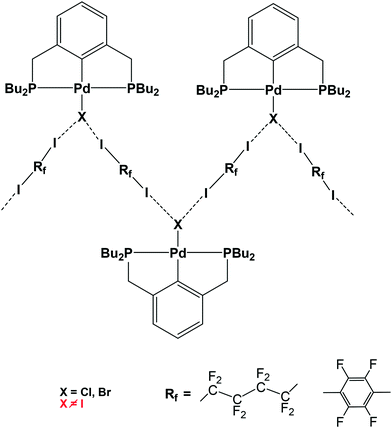
Halogen bond (XB)1-assisted supramolecular self-assembly of transition metal complexes is an attractive research area, developing along with the intensive exploration of XB and other σ- and π-hole2 bonding interactions. Recent advances in this field have been recently reviewed.3 In the XB-assisted supramolecular design, the ditopic diiodides of perfluorated alkyl and aromatic hydrocarbons are common XB-donor building blocks used as linkers between XB-acceptor fragments.4 The same applies to hybrid XB-supported organometallic systems of Pt and Pd affording 1D straight5 and zigzag chains6via I–N and I–X halogen bonds, respectively (see Scheme 1).The formation of the L → M bond results in the strengthening of the X–N halogen bond in M ← Py–X–NH3 (M = Zn, Ag, Co) model systems.7 However, the M → L back-donation may produce the opposite effect and therefore the L → M and M → L interplay deserves special attention in the case of halogen-bonded X–L–M systems.
A comparison of electrostatic surface potential (ESP) maps of halogen atoms linked to electron-withdrawing organic groups with those of metal-bonded halide ligands8 shows the latter to have XB-acceptor character in their p-belt area, and at best a weak XB-donating apical area. The shape of a ligand L p-belt depends upon its anionic character and the extent of mixing of its p- and s-orbitals. Therefore, additional control over the directionality of XB may be achieved through the degree of XB-acceptor hybridization.
Spectroscopic studies including IR, 19F, 15N and 13C NMR, in solution and in the solid phase, are effective in identifying the XB and quantifying its energy.9–12 IR spectroscopy data for Lewis bases in dilute solution, in the presence of iodoethynyl R–C![[triple bond, length as m-dash]](https://www.rsc.org/images/entities/char_e002.gif) C–I XB donors, gives a good correlation between the association constant (Ka) and Hammett parameter (σpara) for diverse substituents R.13 Using IR spectroscopy, it has also been shown that hydrogen bonding (HB) between a halide and the OH group of CpMn(CO)2(hydroxypyridine) induces a redshift of the ν(CO) bands (max. 12 cm−1) owing to the electron donation from the halide anion via a HB–ligand–metal–CO chain.14 In contrast, the electron-withdrawing effect of an I2 molecule on the iodido ligand in [(Me5C5)Fe(CO)2I–I2–IFe(CO)2(Me5C5)] leads to a 7 cm−1 blueshift of the ν(CO) bands with respect to (Me5C5)Fe(CO)2I.15
C–I XB donors, gives a good correlation between the association constant (Ka) and Hammett parameter (σpara) for diverse substituents R.13 Using IR spectroscopy, it has also been shown that hydrogen bonding (HB) between a halide and the OH group of CpMn(CO)2(hydroxypyridine) induces a redshift of the ν(CO) bands (max. 12 cm−1) owing to the electron donation from the halide anion via a HB–ligand–metal–CO chain.14 In contrast, the electron-withdrawing effect of an I2 molecule on the iodido ligand in [(Me5C5)Fe(CO)2I–I2–IFe(CO)2(Me5C5)] leads to a 7 cm−1 blueshift of the ν(CO) bands with respect to (Me5C5)Fe(CO)2I.15
As the shift of the ν(CO) band(s) of metal carbonyls is known to be a sensitive probe for the changes in the electron density at the metal centre, we were interested in investigating the halogen-bonded complexes formed from halide- or organochalcogenolate-substituted metal carbonyls (XB acceptor) and a typical XB donor (p-DITFB). For this purpose, we have assembled organometallic halides and organochalcogenides with p-DITFB in a series of novel cocrystals and studied their crystal and electronic structures by means of XRD methods, IR spectroscopy and DFT calculations.
Results and discussion
In order to assess the ν(CO) shift in halogen-bonded complexes, we have simulated the CpFe(CO)2X–DITFB (X = Cl, I, TePh; DITFB = 1,4-diiodotetrafluorobenzene) system in the gaseous state. Our computational study correctly reproduced the experimentally observed geometry of the complexes and led us to anticipate a 3–4 cm−1 hypsochromic shift of the ν(CO) bands with respect to free CpFe(CO)2TePh (see Table S1_es of the ESI†). The nonpolar nature of hexane and its ability to solubilize CpFe(CO)2TePh seemed to be ideal for the experimental measurement of the XB-induced ν(CO) shift in solution. However, during our first attempt to measure the IR spectra of the (CpFe(CO)2TePh)(p-DITFB) adduct, we observed that the addition of p-DITFB to the green hexane solution of CpFe(CO)2TePh unexpectedly resulted in fast decolorization and precipitation of a dark-green material. Its FTIR-ATR spectrum corresponds to the sum of the IR spectra of CpFe(CO)2TePh and p-DITFB, with a 4 cm−1 hypsochromic shift of the ν(CO) bands when compared to crystalline CpFe(CO)2TePh. Precipitation of XB-assembled cocrystal microparticles by addition of water to a solution in a water-immiscible organic solvent has been reported,16 but to the best of our knowledge, the direct precipitation of two-component crystals just upon mixing of the XB donor and metal–halide or chalcogenolate XB acceptor solutions is unprecedented. Cyclohexane appeared to be an even more suitable nonpolar solvent because it can solubilize CpFe(CO)2TePh in the presence of DITFB. The IR-monitored titration of a 0.025 M solution of CpFe(CO)2TePh in cyclohexane with a 0.01 mmol portion of solid p-DITFB produced a gradual hypsochromic broadening (ca. 4 cm−1 half-width) of the 2019 cm−1ν(CO) band (see Fig. 1 and the ESI†).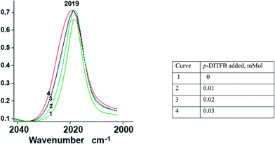 | ||
| Fig. 1 Unsymmetrical hypsochromic broadening (ca. ∼4 cm−1 half-width) of the ν(CO) band at 2019 cm−1 as a result of gradual addition of p-DITFB to a 0.025 mmol cyclohexane solution of CpFe(CO)2TePh. | ||
To investigate the possible influence of direct attractive interactions between p-DITFB and carbonyl groups, we simulated the IR spectra of the I–CO-bonded CpFe(CO)2TePh–p-DITFB adduct (optimized in the gas phase) and found a redshift of the ν(CO) band (see the ESI†). Moreover, the IR-monitored titration of its halogen-free analog CpMn(CO)3 against p-DITFB under the same conditions also showed a slight bathochromic broadening of the ν(CO) bands (see Table S1_es of the ESI†). From these studies, it is clear that a direct I–CO interaction can only redshift the ν(CO) band or reduce its blueshift. The complex interplay between these two opposite effects may be partly responsible for the absence of a clear correlation between the nature of X and the CO blueshift values.
The powder XRD pattern of the CpFe(CO)2TePh/p-DITFB green precipitate from the hexane solution matched well with the simulated powder XRD pattern17 (see Fig. S3_es in the ESI†) based on single crystal XRD data for the dark-green P21/c cocrystals 1 prepared by slow vapor diffusion in CpFe(CO)2TePh–p-DITFB 1![[thin space (1/6-em)]](https://www.rsc.org/images/entities/char_2009.gif) :
:![[thin space (1/6-em)]](https://www.rsc.org/images/entities/char_2009.gif) 1 mixtures in DCM/hexane (see Fig. 1).
1 mixtures in DCM/hexane (see Fig. 1).
Although the C–O distances in the carbonyl ligands of 1 (1.140(3)–1.146(3) Å) are not significantly different from those in the parent CpFe(CO)2TePh (1.140(6)–1.145(4) Å), the ν(CO) frequencies in the FTIR-ATR spectrum of 1 are blueshifted (4 cm−1) with respect to the parent CpFe(CO)2TePh and match well with those of the green precipitate resulting from the interaction of CpFe(CO)2TePh with p-DITFB in hexane (see Table 1). The crystal structure of 1 is revealed to be of type II, having a genuine I–Te halogen bond with a distance of 3.4863(2) Å which is 0.5 Å shorter than the sum of the corresponding van der Waals (vdW) radii. The trimolecular (CpFe(CO)2TePh)2(μ2-DITFB) assemblies are linked by Te–I chalcogen bonds at a distance of 4.2059(2) Å, which is close to the sum of the Te–I vdW radii (see Fig. 2).
| Parent complex, ν, cm−1 | Cocrystal with DITFB, ν, cm−1 | Shift, cm−1 | ||
|---|---|---|---|---|
| a Cocrystals obtained by vapor diffusion (see the Experimental section for details). b Precipitate from cyclo-hexane solution. c Precipitate from n-hexane solution. | ||||
| 1 | CpFe(CO)2TePh | 2007, 1993, 1936 | 2013, 1993, 1941a | 4–6, 0, 4–5 |
| 2011, 1993, 1940b | ||||
| 3 | CpFe(CO)2Cl | 2048, 1990 | 2048, 2003 | 0, 13 |
| 4 | CpFe(CO)2Br | 2035, 1984 | 2044, 1990 | 9, 5 |
| 5 | CpFe(CO)2I | 2026, 1966, 1946 | 2032, 1982, 1962 | 6, 16, 16 |
| 6 | CbCo(CO)2I | 2040, 1992 | 2049, 2003a | 9, 11 |
| 2047, 2001b | ||||
| 2047, 2002c | ||||
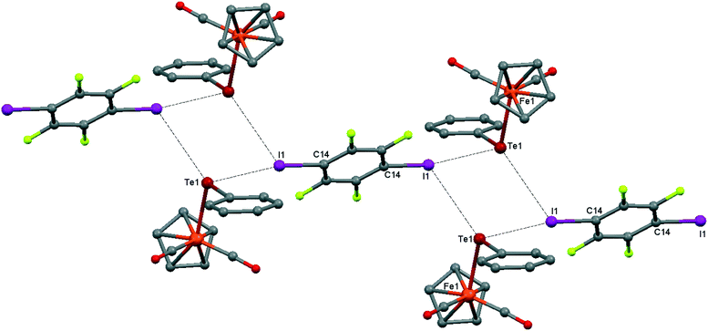 | ||
| Fig. 2 Crystal structure diagram of 1, showing the I–Te halogen-bonded trimolecular assemblies (CpFe(CO)2TePh)2(μ2-DITFB) and the Te–I chalcogen interactions between them. Hydrogen atoms are omitted for clarity. Selected distances (Å): I(1)–Te(1), 3.4863(2); Te(1)–Fe(1), 2.5934(3); Te(1)–I(1), 4.2059(2). Selected angles (°): I(1)–Te(1)–I(1), 90.55(1); Fe(1)–Te(1)–I(1), 108.64(1); Fe(1)–Te(1)–I(1), 95.17(1); Fe(1)–Te(1)–C(8), 102.16(6); Te(1)–I(1)–C(14), 169.71(6). Dotted lines link Te and I atoms at distances shorter than the sum of Te–I vdW radii.18 | ||
It should be noted that the parent CpFe(CO)2TePh crystal exhibits significant static positional disorder with Te–Fe distances of 2.538–2.617 Å and a disordered Cp ring,19 while in 1, the CpFe(CO)2TePh molecules are perfectly ordered leading to a well-defined Te–Fe distance of 2.5934(3) Å (see Fig. 3). Apparently, cocrystallization with an “innocent” XB (or other secondary bonded) counterpart can, in some cases, be an instrument to “fix” disordered structures.
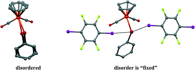 | ||
| Fig. 3 The disorder of CpFe(CO)2TePh molecules in a parent crystal (LADWOE19) is “fixed” by two p-DITFB molecules in cocrystal 1. | ||
Using the same vapor diffusion technique, which offers the advantage of growing crystals under an inert atmosphere, we prepared the following cocrystals of p-DITFB with μ2-SPh, halides (Cl, Br, I) and (tetramethylcyclobutadiene)cobalt(dicarbonyl)iodide [CbCo(CO)2I], which are congeners of CpFe(CO)2TePh: [CpFe(CO)(SPh)]2–DITFB (2), CpFe(CO)2Cl–DITFB (3), CpFe(CO)2Br–DITFB (4), CpFe(CO)2I–DITFB (5) and CbCo(CO)2I–DITFB (6) (see Fig. 4–8, respectively). The interatomic distances in the cyclodienyl–metal–carbonyl moieties in complexes 1–6 are equal or close to those in their parent structures.
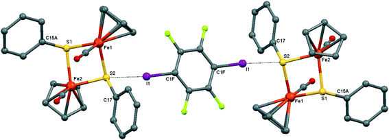 | ||
| Fig. 4 Crystal structure diagram of 2, showing its I–S halogen-bonded trimolecular assemblies ([CpFe(CO)(μ2-SPh)]2)2(μ2-DITFB). Hydrogen atoms are omitted for clarity. Selected distances (Å): I(1)–S(2), 3.130(1). Selected angles (°): C(1F)–I(1)–S(2), 173.9(1); Fe(1)–S(2)–I(1), 111.91(4); I(1)–S(2)–C(17), 102.5(1); I(1)–S(2)–Fe(2), 118.86(4). Dotted lines link S and I atoms at a distance shorter than the sum of the S–I vdW radii.18 | ||
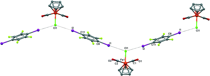 | ||
| Fig. 5 Crystal structure diagram of 3, showing a fragment of I–Cl halogen-bonded polymeric chains ([CpFe(CO)2Cl](μ2-DITFB))n. Hydrogen atoms are omitted for clarity. Selected distances (Å): Fe(1)–Cl(1), 2.318(3); Cl(1)–I(1), 3.219(5); Cl(1)–I(2), 3.229(5). Selected angles (°): I(2)–Cl(1)–I(1), 141.48(3); Fe(1)–Cl(1)–I(1), 110.02(4); Fe(1)–Cl(1)–I(2), 108.33(4); Cl(1)–I(2)–C(11), 173.4(1); Cl(1)–I(1)–C(8), 175.8(1). Dotted lines link Cl and I atoms at distances shorter than the sum of Cl–I vdW radii.18 | ||
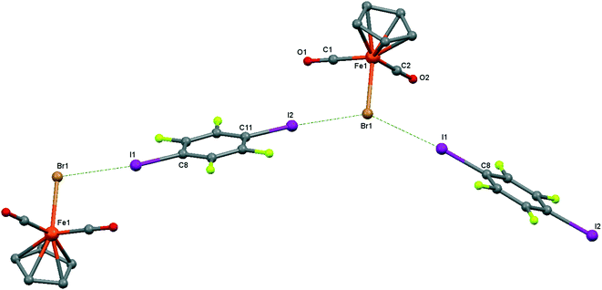 | ||
| Fig. 6 Crystal structure diagram of 4, showing a fragment of I–Br halogen-bonded polymeric chains ([CpFe(CO)2Br](μ2-DITFB))n. Hydrogen atoms are omitted for clarity. Selected distances (Å): Fe(1)–Br(1), 2.4195(5); Br(1)–I(2), 3.2943(4); Br(1)–I(1), 3.3111(4). Selected angles (°): I(2)–Br(1)–I(1), 142.76(1); C(8)–I(1)–Br(1), 172.02(8); Fe(1)–Br(1)–I(1), 107.61(1); Fe(1)–Br(1)–I(2), 109.22(1). Dotted lines link Br and I atoms at a distance shorter than the sum of the Br–I vdW radii.18 | ||
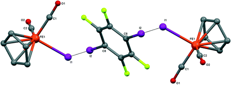 | ||
| Fig. 7 Crystal structure diagram of 5, showing its I–I halogen-bonded trimolecular assemblies (CpFe(CO)2I)2(μ2-DITFB). Hydrogen atoms are omitted for clarity. Selected distances (Å): Fe(1)–I(1), 2.6025(4); I(1)–I(2), 3.5488(3). Selected angles (°): Fe(1)–I(1)–I(2), 89.06(1); C(8)–I(2)–I(1), 175.50(7). Dotted lines link I atoms at a distance shorter than the sum of I–I vdW radii.18 | ||
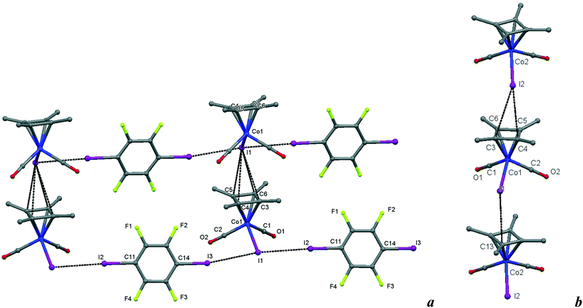 | ||
| Fig. 8 a) Crystal structure diagram of 6, showing a fragment of I–I halogen-bonded polymeric chains ([Cb*Co(CO)2I](μ2-DITFB))n linked by I–π(η4-Me4C4) interactions. Hydrogen atoms are omitted for clarity. Selected distances (Å): intramolecular Co(1)–I(1), 2.619(1); intermolecular I(3)–I(1), 3.589(1); I(1)–I(2), 3.585(1); I(1)–C(3–6) ring of the η4 = Me4C4 ligand, 3.781(7)–3.866(7). Selected angles (°): I(3)–I(1)–I(2), 171.51(2); Co(1)–I(1)–I(3), 93.00(2); Co(1)–I(1)–I(2), 95.16(2); C(14)–I(3)–I(1), 169.6(2); C(11)–I(2)–I(1), 177.2(2). b) Comparison of the Cb*Co(CO)2I stacks in 6 with those in the parent crystal. Selected distances (Å): intermolecular I(2)–C(4), 3.725(8); I(2)–C(3), 3.87(1); I(1)–C(13), 3.842(9), and similarities of the intramolecular distances Co(2)–I(2), 2.598(1); Co(1)–C(2), 1.781(7); C(2)–O(2), 1.157(9); Co(1)–C(1), 1.79(1); C(1)–O(1), 1.16(1). Dotted lines link specific atoms at a distance shorter than the sum of their vdW radii.18 | ||
The solid-state FTIR-ATR data for their ν(CO) frequencies (see Table 1) demonstrate the general blueshift, ranging from 5 to 16 cm−1 when compared to the parent LM(CO)2X crystals. The hypsochromic shift in 5 is also in agreement with the 7 cm−1 blueshift registered in the IR spectrum of the charge transfer complex (Me5C5)Fe(CO)2I–I2 (1965, 2014 cm−1) compared to the parent complex (η5-Me5C5)Fe(CO)2I (1957, 2007 cm−1).15 It is noteworthy that this 7 cm−1 blueshift can be correctly reproduced by the same computational method as used for the evaluation of the ν(CO) blueshift in our complexes 1, 3, and 5 (see the ESI†).
Electron donation from ligand X of LM(CO)2X to the iodine of p-DITFB appears sufficient to withdraw electron density in the X → M bond and reduce M → CO back-bonding.20 This results in a decrease of the occupancy of the π*C–O LUMO and, therefore, a slightly stronger CO bond.
The solid-state structures of cocrystals 1–6 (see Fig. 4–8) are stabilized by short contacts between the halide ligand X of CpFe(CO)2X (X = Cl, Br, I) and the iodine atoms of the ditopic XB acceptor (p-DITFB). The dependence of the I–X–Fe angle on the nature of X is a remarkable illustration of the directionality of XBs.
NBO/PBE0 calculations for [CpFe(CO)2X](p-DITFB) (X = Cl, I, TePh) adducts demonstrate the dominant contribution from the unhybridized apical p-electron pair of iodine in DITFB (see Tables 1 and S1†_es) and p-electrons of the ligand X p-belt. The relative contribution of XB acceptor orbitals to X–I XB and their hybridization do not show much dependence on the nature of ligand X.
The geometry of a pure p-orbital implies certain demands for the XB geometry, thus providing the XB directionality, which was reproduced in our DFT simulation and is visualized in the ESP maps (see Fig. 9).
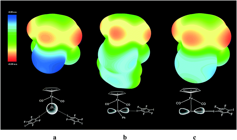 | ||
| Fig. 9 Electrostatic surface potential (ESP) maps for free parent molecules CpFe(CO)2I (a), CpFe(CO)2TePh (b) and CpFe(CO)2Cl (c) showing the nucleophilic areas at the iodine, tellurium and chlorine atoms, respectively. Note that the spherical potential distribution at the Cl ligand in CpFe(CO)2Cl does not dictate specific directionality of I–Cl XB (a), while unhybridized 5p orbitals of Te (b) and I (c)21 direct the X–I XB at the right angle to Fe–TePh and Fe–I bonds. | ||
ESP mapping for CpFe(CO)2I (Fig. 9a) shows the nucleophilic area at the specific equatorial “belt” of the iodine ligand, which is orthogonal to the Fe–I bond and has two distinct maxima matching with the p-orbital as well as with the “docking” sites for XB with electrophilic iodine functions of p-DITFB. One of the equatorial p-orbitals of the Te atom in the TePh ligand of complex CpFe(CO)2TePh is involved in covalent bonding with a carbon atom of the Ph group and therefore Te is left with only one XB-suitable p-orbital, resulting in two clearly visible spots on the ESP map (Fig. 9b) and directing the XB bonding with electrophilic iodine functions of p-DITFB in line with the x-axis, as suggested by the symmetry of the p orbital of Te. The more anionic, and therefore having more isotropic ESP, chloride ligand in CpFe(CO)2Cl does not reveal specific nucleophilic areas, which makes XB bonding more electrostatic and therefore less angular demanding, so that the electrophilic iodines of p-DITFB may exist at angles exceeding 90° (see Fig. 9c).
This increasing directionality of XB bonding in the sequence Cl > Br > I can be an additional reason for the low affinity of the iodine ligand in a sterically crowded (2,6-bis[(di-t-butylphosphino)methyl]phenyl)–Pd–I complex toward its interaction with DITFB and I(CF2)8I XB donors, noted in ref. 6. As shown in Fig. 10, the tert-butyl groups of a 2,6-bis[(di-t-butylphosphino)methyl]phenyl pincer provide efficient shielding of the 5p equatorial “belt” of iodine (which is perpendicular to the Pd–I bond) but allow space for the interaction with the more isotropic and less directionally demanding “sphere” of the Cl ligand.
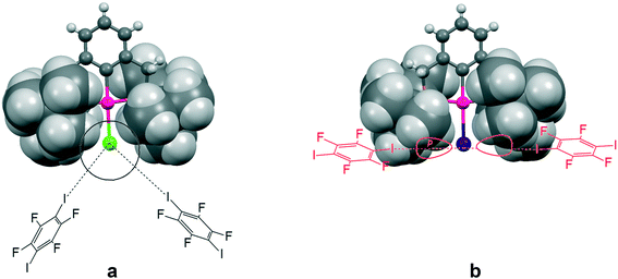 | ||
| Fig. 10 The tert-butyl fragment of a (2,6-bis[(di-t-butylphosphino)methyl]phenyl)PdX (ref. 6) (X = Cl (a) and I (b)) complex is shown as a space filling model to demonstrate the shielding of the 5p equatorial “belt” of the iodide ligand (b), as compared to the spherical chloride “anion” (a), escaping the shield. | ||
We can describe the packing patterns of 3 and 4 as isotypically packed zigzag chains, where the X ligand (Cl, Br) accommodates two p-DITFB molecules, with an average I–X–I angle of 140°, while their TePh, μ2-SPh and iodo congeners 1, 2 and 5 are associated into trimolecular units (CpFe(CO)nX)2(μ2-DITFB). In contrast, iodide 6 forms polymeric chains [(Cb*Co(CO)2I)(μ2-DITFB)]n, with a nearly linear IDITFB–IM–IDITFB angle (see Fig. 2–8).
Finally, it is worth noting that the same phases 1–6 are formed irrespective of the ratio of the starting reagents. With respect to the competition between XB and hydrogen bonding (HB),22 we should also mention that under similar conditions, no supramolecular assembly was observed when 1,4-hydroquinone (a HB donor) was used instead of 1,4-DITFB as a counterpart to the CpFe(CO)2X acceptor.
Summary
We have established that the terminal halogen (Cl, Br, I), TePh, and bridging μ2-SPh ligands in the complexes CpFe(CO)nX and Cb*Co(CO)2X can act as XB acceptors. The XB they form with the iodine atoms of the bidentate XB donor p-DITFB assembles them into trimolecular entities (CpFe(CO)2X)2(μ2-DITFB) or into polymeric ([CpFe(CO)2X](μ2-DITFB))n chains, packed in the cocrystals, which may precipitate instantly from hexane solutions solely upon addition of p-DITFB. These cocrystals exhibit a hypsochromic shift of the carbonyl group vibration bands in their IR spectra of ca. 4–12 cm−1, indicating that the electron-withdrawing effect of the iodine of p-DITFB appears sufficient enough to affect the occupancy of the π*C–O LUMO through I–X–M–π*C–O interactions. These experimental findings are in good agreement with the computational simulation performed on CpFe(CO)2TePh–DITFB, CpFe(CO)2Cl–DITFB and CpFe(CO)2I–DITFB complexes. The symmetry, electrostatic surface potential distribution and availability of the s- and p-orbitals of the XB acceptor ligand in the metal complexes dictate the definite directionality of XBs and the resulting supramolecular architectures. The investigation of this complex interplay may be one of the future perspectives opened by this work.Experimental
All reactions and manipulations were performed using standard Schlenk techniques under an inert atmosphere of pure nitrogen or argon. Solvents were purified, dried and distilled under a nitrogen atmosphere prior to use. Commercial reagents (p-DITFB) were used without additional purification. CpFe(CO)2X (X = Cl, Br, I),23 CpFe(CO)2TePh, CpFe(CO)(μ-SPh)]2 (ref. 24) and Cb*Co(CO)2I (ref. 25) were prepared following the reported procedures. Slow vapour diffusion techniques were used for the preparation of the cocrystals 1–6.IR spectra were recorded on a Bruker Alpha FTIR spectrometer equipped with an ATR facility (for solid samples) and a 0.1 mm CaF2 cell for hexane and cyclohexane solutions.
Preparation of 1–6 (general procedure)
0.1 mmol of CpFe(CO)2X and 0.1 mmol of p-DITFB were dissolved in 0.05 ml of CH2Cl2 in a 5 mm glass tube, and the mixture was placed into a 20 mm/10 ml test tube containing 1 ml of n-heptane in an argon atmosphere, which was closed and left for 48 h at 4 °C. Crystals formed which were used for XRD and IR investigations.Precipitation of CpFe(CO)2TePh–DITFB
To an emerald-green solution of 2 mg (∼0.005 mmol) of CpFe(CO)2TePh in n-hexane (1 ml) in a 2 ml Eppendorf tube, 0.008 g (0.02 mmol) of p-DITFB was added and the mixture was shaken several times to ensure complete dissolution. After several seconds, a green precipitate formed, leaving a pale greenish-yellow solution. The green solid residue was washed with hexane, dried in a flow of argon and subjected to IR measurement using the ATR attachment.Crystal structure determination of compounds 1–7
Powder XRD
The powder diffraction pattern of the sample was recorded at room temperature on a Bruker D8 Advance Vario powder diffractometer, equipped with a copper anode (Cu Kα1), a Ge(111) monochromator, and a position-sensitive LynxEye detector (6–90° 2θ interval, 0.01° steps). The diffraction data was processed and analyzed using Bruker Topas5 (ref. 26) software. The investigated sample is single-phase. The simulation of the diffraction pattern by the Rietveld method is confirmed by the phase composition of the sample phase, which is determined from the single crystal diffraction data. The discrepancy parameters are: Rwp = 3.29%, Rp = 2.51%, ,
,  , and RBragg = 2.266%. The unit cell parameters are as follows: a = 13.73614(15) Å, b = 11.69728(14) Å, c = 11.85569(14) Å, and β = 15.2909(8)°.
Single crystal XRD
Crystals of 1–7 suitable for XRD investigation were grown by slow evaporation of a dichloromethane/n-hexane solvent mixture by varying the temperature from 25 °C to 0 °C. Relevant crystallographic data and the details of measurements are given in the ESI.†A Bruker APEX II CCD area detector diffractometer equipped with a graphite-monochromated Mo Kα radiation source (0.71070 Å) was used for cell determination and intensity data collection for compounds 1–6. The structure was solved by direct methods and refined by full-matrix least squares against F2 using SHELXL-97 and Olex2 software.27,28 Non-hydrogen atoms were refined with anisotropic thermal parameters. All hydrogen atoms were geometrically fixed and refined using a riding model. Atomic coordinates and other structural parameters of 1–7 have been deposited with the Cambridge Crystallographic Data Centre (CCDC no. 1587662 (1), 1587659 (2), 1587660 (3), 1587664 (4), 1587663 (5), 1587661 (6), and 1587665 (7)).
Calculation details
Theoretical calculations were carried out with the ORCA 4.01 program package.29 A non-hybrid PBE functional,30 dispersion correction with Becke–Johnson damping (D3BJ)31 and a def2-TZVP basis set32 with a small-core pseudopotential for Te and I atoms33 were used for geometry optimization and Hessian calculation. The def2/J auxiliary basis set34 was used for Coulomb fitting. Single point energies were calculated on these geometries using the hybrid functional PBE0 (ref. 35) with the same basis set and dispersion correction. NBO analysis was performed at this level of theory using the NBO 6.0 program.36 Single point energies of DITFB adduct formation were also evaluated by means of new domain-based local pair natural orbital coupled cluster theory with single, double, and perturbative triple excitations (DLPNO-CCSD(T)37 using def2 triple and quadruple-zeta basis sets29 and appropriate correlation fitting basis sets).38 Extrapolation to the complete basis set limit39 was performed using parameters α = 10.39, β = 2.4 and α = 7.88, β = 3 for “cardinal numbers” 2, 3 and 3, 4, respectively.40Conflicts of interest
There are no conflicts to declare.Acknowledgements
We gratefully acknowledge the financial support from the Russian Foundation for Basic Research (grant no. 16-03-00798) and DST India (YSS\2018\000034). We thank the Instrumental Centers of N. S. Kurnakov Institute of General and Inorganic Chemistry and A. N. Nesmeyanov Institute of Organoelement Compounds (Russian Academy of Sciences) for XRD, PXRD and FTIR measurements.References
- (a) G. R. Desiraju, P. S. Ho, L. Kloo, A. C. Legon, R. Marquardt, P. Metrangolo, P. Politzer, G. Resnati and K. Rissanen, Pure Appl. Chem., 2013, 85, 1711–1713 CrossRef CAS; (b) G. Cavallo, P. Metrangolo, R. Milani, T. Pilati, A. Priimagi, G. Resnati and G. Terraneo, Chem. Rev., 2016, 116, 2478–2601 CrossRef CAS PubMed.
- (a) P. Politzer, J. S. Murray and T. Clark, Phys. Chem. Chem. Phys., 2013, 15, 11178–11189 RSC; (b) H. Wang, W. Wang and W. J. Jin, Chem. Rev., 2016, 116, 5072–5104 CrossRef CAS PubMed.
- (a) B. Li, S.-Q. Zang, L.-Y. Wang and T. C. W. Mak, Coord. Chem. Rev., 2015, 308, 1–21, DOI:10.1016/j.ccr.2015.09.005; (b) R. W. Troff, T. Mäkelä, F. Topić, A. Valkonen, K. Raatikainen and K. Rissanen, Eur. J. Org. Chem., 2013, 1617–1637, DOI:10.1002/ejoc.201201512; (c) R. Bertani, P. Sgarbossa, A. Venzo, F. Lelj, M. Amati, G. Resnati, T. Pilati, P. Metrangolo and G. Terraneo, Coord. Chem. Rev., 2010, 254, 677–695 CrossRef CAS.
- C. Perkins, S. Libri, H. Adams and L. Brammer, CrystEngComm, 2012, 14, 3033–3038 RSC.
- P. Sgarbossa, R. Bertani, V. Di Noto, M. Piga, G. A. Giffin, G. Terraneo, T. Pilati, P. Metrangolo and G. Resnati, Cryst. Growth Des., 2012, 12, 297, DOI:10.1021/cg201073m.
- M. T. Johnson, Z. Džolić, M. Cetina, O. F. Wendt, L. Öhrström and K. Rissanen, Cryst. Growth Des., 2012, 12, 362–368 CAS.
- Y. Wang, W. Wu, Y. Liu and Y. Lu, Chem. Phys. Lett., 2013, 578, 38–42, DOI:10.1016/j.cplett.2013.06.005.
- L. Brammer, G. M. I. Espallargas and S. Libri, CrystEngComm, 2008, 10, 1712–1727, 10.1039/b812927d.
- C. B. Aakeröy, M. Baldrighi, J. Desper, P. Metrangolo and G. Resnati, Chem. – Eur. J., 2013, 19, 16240–16247 CrossRef PubMed.
- M. G. Sarwar, B. Dragisic, L. J. Salsberg, C. Gouliaras and M. S. Taylor, J. Am. Chem. Soc., 2010, 132, 1646–1653 CrossRef CAS PubMed.
- A. Bauzà, D. Quiñonero, A. Frontera and P. M. Deyà, Phys. Chem. Chem. Phys., 2011, 13, 20371–20379 RSC.
- R. A. Thorson, G. R. Woller, Z. L. Driscoll, B. E. Geiger, C. A. Moss, A. L. Schlapper and N. P. Bowling, Eur. J. Org. Chem., 2015, 1–12, DOI:10.1002/ejoc.201403671.
- (a) C. Laurence, M. Queignec-Cabanetos, T. Dziembowska, R. Queignec and B. Wojtkowiak, J. Am. Chem. Soc., 1981, 103, 2567–2573 CrossRef CAS; (b) C. Laurence, M. Queignec-Cabanetos and B. Wojtkowiak, J. Chem. Soc., Perkin Trans. 2, 1982, 1605–1610 RSC; (c) C. Laurence, M. Queignec-Cabanetos and B. Wojtkowiak, Can. J. Chem., 1983, 61, 135–138 CrossRef CAS.
- J. W. Kee and W. Y. Fan, J. Organomet. Chem., 2013, 729, 14–19 CrossRef CAS.
- N. Masuhara, S. Nakashima and K. Yamada, Chem. Lett., 2005, 34, 1352 CrossRef CAS.
- (a) X. Pang, H. Wang, X. R. Zhao and W. J. Jin, CrystEngComm, 2013, 15, 2722–2730 RSC; (b) H. Y. Gao, Q. J. Shen, X. R. Zhao, X. Q. Yan, X. Pang and W. J. Jin, J. Mater. Chem., 2012, 22, 5336 RSC.
- Mercury 3.6 (Build RC6) CCDC 2015.
- S. Alvarez, Dalton Trans., 2013, 42, 8617 RSC.
- Yu. V. Torubaev, A. A. Pasynsky and I. V. Skabitsky, Russ. J. Coord. Chem., 2009, 35, 347 CrossRef.
- G. Bistoni, S. Rampino, N. Scafuri, G. Ciancaleoni, D. Zuccaccia, L. Belpassi and F. Tarantelli, Chem. Sci., 2016, 7, 1174–1184 RSC.
- I. V. Alabugin, S. Bresch and M. Manoharan, J. Phys. Chem. A, 2014, 118, 3663–3677 CrossRef CAS PubMed.
- S. Panikkattu, P. D. Chopade and J. Desper, CrystEngComm, 2013, 3125–3136 Search PubMed.
- Synthetic Methods of Organometallic and Inorganic Chemistry, ed. W. A. Herrmann and G. Thieme, Stuttgart, Germany, vol. 82, p. 107 CrossRef CAS; E. D. Scheremer and W. H. Baddley, J. Organomet. Chem., 1971, 27, 83–88 CrossRef CAS; E. V. Mutseneck, D. A. Loginov, D. S. Perekalin, Z. A. Starikova, D. G. Golovanov, P. V. Petrovskii, P. Zanello, M. Corsini, F. Laschi and A. R. Kudinov, Organometallics, 2004, 23, 5944–5957 CrossRef.
- E. D. Scheremer and W. H. Baddley, J. Organomet. Chem., 1971, 27, 83–88 CrossRef.
- E. V. Mutseneck, D. A. Loginov, D. S. Perekalin, Z. A. Starikova, D. G. Golovanov, P. V. Petrovskii, P. Zanello, M. Corsini, F. Laschi and A. R. Kudinov, Organometallics, 2004, 23, 5944–5957 CrossRef CAS.
- Bruker TOPAS 5 User Manual.—Bruker AXS GmbH, Karlsruhe, Germany, 2015 Search PubMed.
- G. M. Sheldrick, Acta Crystallogr., Sect. A: Found. Crystallogr., 2008, 64, 112 CrossRef CAS PubMed.
- O. V. Dolomanov, L. J. Bourhis, R. J. Gildea, J. A. K. Howard and H. Puschmann, J. Appl. Crystallogr., 2009, 42, 339–341 CrossRef CAS.
- F. Neese, "Software update: the ORCA program system, version 4.0" WIREs Comput Mol Sci 2017, p. e1327, DOI:10.1002/wcms.1327.
- (a) J. P. Perdew, K. Burke and M. Ernzerhof, Phys. Rev. Lett., 1996, 77, 3865 CrossRef CAS PubMed; (b) J. P. Perdew, K. Burke and M. Ernzerhof, Phys. Rev. Lett., 1997, 78, 1396 CrossRef CAS.
- (a) S. Grimme, S. Ehrlich and L. Goerigk, J. Comput. Chem., 2011, 32, 1456 CrossRef CAS PubMed; (b) S. Grimme, J. Antony, S. Ehrlich and H. Krieg, J. Chem. Phys., 2010, 132, 154104 CrossRef PubMed.
- F. Weigend and R. Ahlrichs, Phys. Chem. Chem. Phys., 2005, 7, 3297 RSC.
- K. A. Peterson, D. Figgen, E. Goll, H. Stoll and M. Dolg, J. Chem. Phys., 2003, 119, 11113–11123 CrossRef CAS.
- F. Weigend, Phys. Chem. Chem. Phys., 2006, 8, 1057 RSC.
- C. Adamo and V. J. Barone, J. Chem. Phys., 1999, 110, 6158–6170 CrossRef CAS.
- E. D. Glendening, J. K. Badenhoop, A. E. Reed, J. E. Carpenter, J. A. Bohmann, C. M. Morales, C. R. Landis and F. Weinhold, Theoretical Chemistry Institute, University of Wisconsin, Madison, WI, 2013, http://nbo6.chem.wisc.edu/.
- C. Riplinger, P. Pinski, U. Becker, E. F. Valeev and F. Neese, J. Chem. Phys., 2016, 144, 024109 CrossRef PubMed.
- A. Hellweg, C. Hattig, S. Hofener and W. Klopper, Theor. Chem. Acc., 2007, 117, 587 CrossRef CAS.
- (a) W. Klopper and W. Kutzelnigg, THEOCHEM, 1986, 135, 339–356 CrossRef; (b) W. Kutzelnigg, Int. J. Quantum Chem., 1994, 51, 447–463 CrossRef CAS; (c) S. J. Zhong, E. C. Barnes and G. A. Petersson, J. Chem. Phys., 2008, 129, 184116 CrossRef PubMed.
- D. G. Truhlar, Chem. Phys. Lett., 1998, 294, 45–48 CrossRef CAS.
Footnote |
| † Electronic supplementary information (ESI) available. CCDC 1587659–1587665. For ESI and crystallographic data in CIF or other electronic format see DOI: 10.1039/c7ce02185b |
| This journal is © The Royal Society of Chemistry 2018 |

