Enhanced photoluminescence of gallium phosphide by surface plasmon resonances of metallic nanoparticles
Guanjun Lin,
Qian Zhang,
Xiaoyu Lin,
Dongfang Zhao,
Ran Jia,
Naikun Gao,
Zhiyuan Zuo,
Xiangang Xu and
Duo Liu*
State Key Laboratory of Crystal Materials, Shandong University, 27 South Shanda Road, Jinan, Shandong 250100, P. R. China. E-mail: liuduo@sdu.edu.cn; Tel: +86-531-88363901
First published on 25th May 2015
Abstract
We report here enhanced photoluminescence (PL) from GaP, an indirect band gap semiconductor, by metallic Au and Ag nanoparticles. The metallic Au and Ag nanoparticles were sputtering-coated onto GaP followed by heat treatment. After optimization of the surface coverage ratios, we find 5.6-fold and 14.5-fold PL enhancement for the Au and Ag coated samples, respectively. Time resolved photoluminescence spectroscopy indicates that Ag nanoparticles can effectively accelerate the PL decay time. Our results indicate that the PL enhancement comes from enhanced photon scattering and localized field enhancement of metallic Au and Ag nanoparticles.
Introduction
Surface plasmon resonances (SPRs) are collective electron oscillations induced by incident light on metal surfaces, which have attracted considerable attention in many fields of modern science and techniques.1–3 Localized surface plasmon resonances (LSPRs) are confined surface plasmons on metallic nanoparticles with sizes comparable to or smaller than the wavelength of incident light.4–6 The frequency and intensity of LSPRs strongly depend on the types of materials (typically, Au, Ag, Al and Pt), and are sensitive to the shape, size, components and the dielectric environment.7–11 Metallic nanoparticles that support LSPRs exhibit many interesting characteristics, including enhanced local electrical field, increased optical absorption and scattering cross sections.12–16 Because of these unique properties, metallic nanostructures have attracted considerable attentions for applications in light emitting diodes (LEDs), solar cells, photoluminescence (PL), photocatalysis, and chemical and biosensing.17–22Gallium phosphide (GaP), an indirect band gap (2.26 eV) semiconductor, has been widely used in photoelectronic devices.23 However, because of the indirect band gap, GaP suffers from low radiative emission efficiency and a small absorbance cross section, resulting in decreased PL intensity than direct band gap semiconductors and organic dyes, which have greatly hindered their applications. Although metallic nanoparticles are largely utilized to increase the possibility of nonlinear process, e.g. Raman scattering, their potentials to increase optical emission have also been noticed.24 For example, Biteen et al. reported 4-fold enhancement of optical emission for Si nanocrystals by nanoporous gold.25 Cheng et al. obtained 15-fold PL enhancement for ZnO films coated with Ag islands.26 Okamoto et al. achieved 17-fold increase in the PL intensity along with a 7-fold increase of the internal quantum efficiency (IQE) from InGaN/GaN multiple quantum wells by nanoparticles Ag layers.27
In this article, we exploit the possibility of using metallic nanoparticles to increase the PL emission efficiency of GaP. It is found both Au and Ag nanoparticles can greatly increase the PL emission of GaP. After optimization of the surface coverage ratios, we find 5.6-fold and 14.5-fold PL enhancement for Au and Ag coated samples, respectively. Time resolved photoluminescence spectroscopy indicates that Ag nanoparticles can effectively accelerate the PL decay time. The underlying principles of the enhanced PL are discussed.
Results and discussion
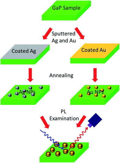
Fig. 1 shows the schematic for fabricating Ag and Au nanoparticles on GaP. The Au and Ag nanoparticles were obtained by sputtering in a sputtering coater (ETD-2000, China) for different periods of time at 10 mA. Nitrogen was aerated into the chamber to prevent Ag from oxidation. After sputtering, the Au-coated samples were heat treated at 180 °C in air for 60 min, and the Ag-coated samples were heat treated at 250 °C in nitrogen for 20 min. The PL spectra of all the samples were obtained by optical excitation at 390 nm of a xenon lamp with an incidence angle of 45° at room temperature.Fig. 2 shows the SEM images of Au and Ag nanoparticles on GaP surface after sputtering for different periods of time. Both Au and Ag nanoparticles are hemisphere in shape and randomly distributed on the sample surfaces. Note that the size and density of Au nanoparticles increase rapidly with the sputtering time (Fig. 2a, c and e). The diameters of the Au nanoparticles increase from ∼10 to ∼15 to ∼40 nm and the density increases from 1.03 × 10¹⁰ to 2.48 × 10¹⁰ to 4.74 × 1010 cm−2 after sputtering for 3, 5, and 10 s, respectively. When the sputtering time is 20 s, the Au nanoparticles connected with each other and form a continuous network (Fig. 2g). However, for Ag-coated samples, the size of Ag nanoparticles does not change significantly with the elongation of the sputtering time, which show relatively uniform size of ∼30 nm (Fig. 2b, d, f and h). The densities of Ag nanoparticles are 0.73 × 10¹⁰, 1.12 × 10¹⁰, 2.56 × 10¹⁰, and 5.04 × 1010 cm−2 for sputtering times of 3, 5, 10 and 20 s, respectively.
As oxide layer on metal nanoparticles may alternate their optical emission behaviors, we examine the surface states of both Au and Ag coated GaP samples by XPS. Fig. 3 shows the XPS spectra of Au 4f and Ag 3d peaks for samples obtained after sputtering for 5 s, respectively. The peaks in Fig. 3a located at 84.05 and 87.7 eV correspond to the binding energies of Au 4f7/2 and 4f5/2, respectively.28 No obvious satellite peaks or shoulder are found in the Au 4f XPS spectrum, indicating that the Au mainly exhibits zero state. Similarly, the XPS peaks in Fig. 3b located at 368.15 and 374.15 eV correspond to the binding energies of Ag 3d5/2 and 3d3/2, respectively, which also indicate the zero oxidation state of Ag.29
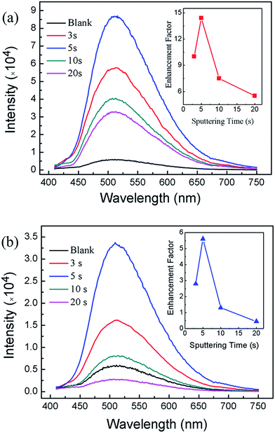
Fig. 4 shows the room temperature PL spectra of samples. The PL spectrum of blank GaP without Au or Ag nanoparticles is also included for comparison. It was obvious that the PL intensities of the samples coated with metallic nanoparticles have been greatly enhanced. For Au-coated samples, the maximum emission peak appears at 509 nm (Fig. 4a), while for Ag coated samples, the maximum emission peak is located at 508 nm (Fig. 4b). Note that the maximum emission peak for blank sample is located at 511 nm. This slight blue shift could possibly be attributed to electron transfers from LSPRs state of metallic nanoparticles to GaP.30 The PL enhancement factors are defined as the ratio between the PL intensity for metal nanoparticles coated samples to that of the blank GaP sample. The inset of Fig. 4 shows the dependence of PL enhancement factors on the sputtering time. The enhancement factors initially increase and then decrease with the sputtering time. For Au coated samples, a maximum enhancement factor of 5.6 is obtained on sample sputtering coated for 5 s, corresponding to a density of Au nanoparticles of 2.48 × 1010 cm−2. For Au-coated sample for 20 s, the enhancement factor is less than 1. This could be correlated to that too many Au nanoparticles coated GaP surface result in the incident light cannot effectively reach the GaP surface. It seems that close-packed metal nanoparticles have blocked the incident light from reaching the GaP. A recent study also suggests that close-packed metal nanoparticles could reduce the possibility of the radiative recombination process.31 Interestingly, the PL enhancement for Ag coated samples are greater than that of Au coated samples. A maximum PL enhancement factor of 14.5 is obtained for sample sputtering coated for 5 s (Fig. 4b).
In order to understand the effects of Au and Ag nanoparticles on the optical properties of the samples, we study the reflectance of the samples. The results are discussed with emphasis on the optical absorptions at 390 nm. Fig. 5 shows the reflectance of the blank sample and the samples coated with Au and Ag nanoparticles after sputtering for 5 s, respectively. For the blank sample, the reflectance was about 39.6% at 390 nm, in excellent agreement with an early study.32 After sputtering coated with metallic nanoparticles, the reflectance of Au-coated sample is slightly reduced by 0.42% than that of blank sample at 390 nm, while the Ag-coated sample shows reflectance reduced by 3.49%. This observation can be attributed to enhanced forward scattering of incident optical wave by metallic nanoparticles.33
We also performed TRPL measurement for the Au and Ag coated samples obtained by sputtering for 5 s at room temperature, as shown in Fig. 6. The PL peaks were centered at 510 nm. The PL decays are fitted by using a biexponential function. The results show that all PL decays showed two kinds of PL recombination lifetimes. For blank samples, the lifetimes are 1.37 ns and 8.14 ns, corresponding to the direct and indirect transitions, respectively. After coated with Au nanoparticles, the lifetimes do not show significant changes (Fig. 6a). While for Ag coated sample (Fig. 6b), the direct transition lifetime is significantly reduced, suggesting that LSPRs of Ag nanoparticles can greatly increase the PL decay rates. Similar observations have been reported on other semiconductor materials.34,35
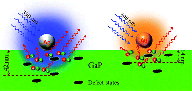
Fig. 7 shows the possible mechanism for the LSPRs of metallic nanoparticles to enhance PL of GaP. Firstly, plasmonic nanoparticles could enhance light scattering.35–38 Existing studies have confirmed that the scattering cross-section can be dramatically increased for LSPRs, resulting in more light scattered into the semiconductor.38 However, the reflectance measurements (Fig. 5) indicate that the scattering effect of metallic nanoparticles is not the main reason for the enhanced PL. Secondly, LSPRs can significantly improve the internal quantum efficiency (ηint) of a nearby semiconductor, which is determined by the ratio of the radiative and nonradiative recombination rates of carries.25,32 The internal quantum efficiency (ηint) is given by:
 | (1) |
 | (2) |
Experimental
The GaP samples used in this study were 8 μm thickness films with an orientation in 15° off-axis from [100] to [111] direction. First, the GaP samples were ultrasonically washed in sequence with deionized water, acetone, and anhydrous ethanol, respectively. The surface morphology of the samples was characterized by scanning electron microscopy (SEM, Hitachi S-4800, Japan). The surface oxidation states of the samples were studied by X-ray photoelectron spectroscopy (XPS, Thermo Scientific ESCALAB 250, Germany) equipped with a monochromatic Al Kα excitation source. The PL and time resolved photoluminescence (TRPL) decay curves were measured by a fluorescence spectrometer (PL, FLS920, UK). The reflectance spectra were measured by an ultraviolet spectrophotometer (UV1901PC, China).Conclusions
In this paper, we investigate the enhancement effects of plasmonic nanostructures on the PL characteristics of the GaP coated by Ag and Au nanoparticles. Our results show that there is an optimal coverage density for the enhancement of PL, which indicates that nanoparticle spacing played an important role for PL enhancement. In our experiment, a sputtering time of 5 s for Ag and Au results in the best PL enhancement, which corresponds to coverage densities of 1.12 × 10¹⁰ and 2.48 × 1010 cm−2 for Ag and Au, respectively. We obtained a maximum 14.5-fold PL enhancement for Ag coated sample, while the enhancement effects for Au coated sample is much smaller since the excitation light (390 nm) cannot effectively excite the LSPRs of Au nanoparticles. The PL enhancement factor for GaP coated with Au nanoparticles was only 5.6 when the sputtering time was 5 s. The TRPL results show that the emitting rate can be accelerated by LSPRs of Ag nanoparticles to improve the internal quantum efficiency. The results reported in this study could be adopted to improve the performance of other optoelectronic devices, such as photodetectors, light emitter, waveguides, optical modulators, and may offer realistic alternatives to various materials that suffer from low quantum efficiencies.Acknowledgements
The authors thank National Science Foundation of China (NSFC) (Grant no. 91233122, 51472143, 91123007), the Fundamental Research Funds of Shandong University (Grant no. 2014JC032 and 2014YQ003), SRF for ROCS, State Education Ministry, and National Basic Research Program of China (973 Program) (Grant no. 2009CB930503) for financial support.Notes and references
- S. A. Maier, Plasmonics: Fundamentals and Applications, Springer-Verlag, New York, 2007, pp. 21–34 Search PubMed.
- W. L. Barnes, A. Eereux and T. W. Ebbesen, Nature, 2003, 424, 824–830 CrossRef CAS PubMed.
- J. M. Pitarke, V. M. Silkin, E. V. Chulkov and P. M. Echenique, Rep. Prog. Phys., 2007, 70, 1–87 CrossRef CAS.
- E. Hutter and J. H. Fendler, Adv. Mater., 2004, 16, 1685–1706 CrossRef CAS PubMed.
- X. Zhang, Y. L. Chen, R. S. Liu and D. P. Tsai, Rep. Prog. Phys., 2013, 76, 046401 CrossRef PubMed.
- M. Pelton, J. Aizpurua and G. Bryant, Laser Photonics Rev., 2008, 2, 136–159 CrossRef CAS PubMed.
- C. Noguez, J. Phys. Chem. C, 2007, 111, 3806–3819 CAS.
- M. Rycenga, C. M. Cobley, J. Zeng, W. Li, C. H. Moran, Q. Zhang, D. Qin and Y. Xia, Chem. Rev., 2011, 111, 3669–3712 CrossRef CAS PubMed.
- C. Burda, X. Chen, R. Narrayanan and M. A. El-Sayed, Chem. Rev., 2005, 105, 1025–1102 CrossRef CAS PubMed.
- D. Y. Lei, J. Li and H. C. Ong, Appl. Phys. Lett., 2007, 91, 021112 CrossRef PubMed.
- K. L. Kelly, E. Coronado, L. L. Zhao and G. C. Schatz, J. Phys. Chem. B, 2003, 107, 668–677 CrossRef CAS.
- R. A. Dynich and A. N. Ponyavina, J. Appl. Spectrosc., 2008, 75, 832–838 CrossRef CAS.
- S. G. Kumar and L. G. Devi, J. Phys. Chem. A, 2011, 115, 13211–13241 CrossRef CAS PubMed.
- R. Sellappan, M. G. Nielsen, F. Gonzalez-Posada, P. C. K. Vesborg, I. Chorkendorff and D. Chakarov, J. Catal., 2013, 307, 214–221 CrossRef CAS PubMed.
- D. Qu, F. Liu, J. Yu, W. Xie, Q. Xu, X. Li and Y. Huang, Appl. Phys. Lett., 2011, 98, 113119 CrossRef PubMed.
- K. R. Catchpole and A. Polman, Appl. Phys. Lett., 2008, 93, 191113 CrossRef PubMed.
- C. Y. Cho, S. J. Lee, J. H. Song, S. H. Hong, S. M. Lee, Y. H. Cho and S. J. Park, Appl. Phys. Lett., 2011, 98, 051106 CrossRef PubMed.
- K. Okamoto, I. Niki, A. Shvartser, Y. Narukawa, T. Mukai and A. Scherer, Nat. Mater., 2004, 3, 601–605 CrossRef CAS PubMed.
- E. Fort and S. Gresillon, J. Phys. D: Appl. Phys., 2008, 41, 013001 CrossRef.
- D. R. Jung, J. Kim, S. Nam, C. Nahm, H. Choi, J. I. Kim, J. Lee, C. Kim and B. Park, Appl. Phys. Lett., 2011, 99, 041906 CrossRef PubMed.
- E. Petryayeva and U. J. Krull, Anal. Chim. Acta, 2011, 706, 8–24 CrossRef CAS PubMed.
- S. K. Gray, Plasmonics, 2007, 2, 143–146 CrossRef CAS.
- M. B. Panish and H. C. Cassey Jr, J. Appl. Phys., 1969, 40, 163–167 CrossRef CAS PubMed.
- E. Fort and S. Gresillon, J. Phys. D: Appl. Phys., 2008, 41, 013001 CrossRef.
- J. S. Biteen, D. Pacifici, N. S. Lewis and H. A. Atwater, Nano Lett., 2005, 5, 1768–1773 CrossRef CAS PubMed.
- P. Cheng, D. Li, X. Li, T. Liu and D. Yang, J. Appl. Phys., 2009, 106, 063120 CrossRef PubMed.
- K. Okamoto, I. Niki, A. Shvartser, Y. Narukawa, T. Mukai and A. Scherer, Nat. Mater., 2004, 3, 601–605 CrossRef CAS PubMed.
- T. D. Thomas and P. Weightman, Phys. Rev. B, 1986, 33, 5406–5413 CrossRef CAS.
- A. Gutes, I. Laboriante, C. Carraro and R. Maboudian, J. Phys. Chem. C, 2009, 113, 16939–16944 CAS.
- X. D. Zhou, X. H. Xiao, J. X. Xu, G. X. Cai, F. Ren and C. Z. Jiang, EPL, 2011, 93, 57009 CrossRef.
- C. Rockstuhl, S. Fahr and F. Lederer, J. Appl. Phys., 2008, 104, 123102 CrossRef PubMed.
- D. E. Aspnes and A. A. Studna, Phys. Rev. B, 1983, 27, 985–1009 CrossRef CAS.
- S. H. Lim, W. Mar, P. Matheu, D. Derkacs and E. T. Yu, J. Appl. Phys., 2007, 101, 104309 CrossRef PubMed.
- K. Okamoto, I. Niki, A. Scherer, Y. Narukawa, T. Mukai and Y. Kawakami, Appl. Phys. Lett., 2005, 87, 071102 CrossRef PubMed.
- T. Ozel, I. M. Soganic, S. Nizamoglu, I. O. Huyal, E. Mutlugun, S. Sapra, K. Gaponik, A. Eychmuller and H. V. Demir, New J. Phys., 2008, 10, 083035 CrossRef.
- H. R. Stuart and D. G. Hall, Appl. Phys. Lett., 1996, 69, 2327–2329 CrossRef CAS PubMed.
- H. R. Stuart and D. G. Hall, Appl. Phys. Lett., 1998, 73, 3815–3817 CrossRef CAS PubMed.
- V. E. Ferry, J. N. Munday and H. A. Atwater, Adv. Mater., 2010, 22, 4794–4808 CrossRef CAS PubMed.
- K. Okamoto, S. Vyawahare and A. Scherer, J. Opt. Soc. Am. B, 2006, 23, 1674–1678 CrossRef CAS.
- S. Linic, P. Christopher and D. B. Ingram, Nat. Mater., 2011, 10, 911–921 CrossRef CAS PubMed.
- C. Clavero, Nat. Photonics, 2014, 8, 95–103 CrossRef CAS PubMed.
| This journal is © The Royal Society of Chemistry 2015 |


