
 Open Access Article
 This Open Access Article is licensed under a
 Creative Commons Attribution 3.0 Unported Licence
A review on the recent advances in the design and structure–activity relationship of TiO2-based photocatalysts for solar hydrogen production
Sunesh S.
Mani
 a,
Sivaraj
Rajendran
a,
Thomas
Mathew
*a and
Chinnakonda S.
Gopinath
*bc
a,
Sivaraj
Rajendran
a,
Thomas
Mathew
*a and
Chinnakonda S.
Gopinath
*bc
aDepartment of Chemistry, St. John's College (Affiliated to University of Kerala), Anchal, Kerala – 691306, India. E-mail: thomasm74@gmail.com
bCatalysis and Inorganic Chemistry Division, CSIR – National Chemical Laboratory, Dr Homi Bhabha Road, Pune 411 008, India. E-mail: cs.gopinath@ncl.res.in
cAcademy of Scientific and Innovative Research (AcSIR), Ghaziabad 201002, India
First published on 10th June 2024
Abstract
The major issues that determine the efficiency of photocatalyst composite materials for solar hydrogen production, with or without a sacrificial agent, are efficient visible light harvesting properties, efficient separation of charge carriers and their utilization of redox sites, and stability. Thus, significant efforts have been devoted in the past few decades to modify the above characteristics by integrating constituent components of composites using different approaches. In the present review, we aim to summarize the recent advances, predominantly, in the area of TiO2-based photocatalyst composites for solar hydrogen production. Firstly, we present the recent progress in material integration aspects by discussing the integration of TiO2 with different categories of materials, including noble/3d metals, metal oxides/sulphides/selenides, other low bandgap semiconductors, C-based materials, and dye sensitizers. Furthermore, we discuss how material integration helps in tailoring the electronic and optical properties for activity tuning in solar H2 production. Subsequently, critical changes in the physico-chemical and electronic properties of composites with respect to their preparation methods, morphology, crystallographic facets, particle size, dopant, calcination temperature, and structure–activity relationship to solar hydrogen production are addressed in detail. Moreover, we discuss the importance of fabricating a photocatalyst in a thin film form and performing solar hydrogen production in different reactor set-ups for enhancing its photocatalytic performance, while addressing device scalability. Despite the significant advancements made in this field, solar-to-hydrogen conversion efficiency still needs to be improved to realise the practical application of solar hydrogen production. In this case, the direct conversion of water to hydrogen via overall water splitting and renewable H2 production from wastewater or biomass components by employing suitable photocatalysts are some possible ways to improve the energy efficiency, and continuous research in the above directions is highly desirable.
 Sunesh S. Mani | Sunesh S Mani completed his Master's Degree in Chemistry from the University of Kerala, Trivandrum. He is currently working as a PhD student under the supervision of Dr Thomas Mathew, Department of Chemistry, St. John's College, Anchal, affiliated to the University of Kerala, Trivandrum. His primary research interest is the development of nanomaterials for photocatalytic applications. |
 Sivaraj Rajendran | Sivaraj Rajendran received his Bachelor's Degree and Master's Degree in Chemistry from the University of Kerala, Trivandrum. He is presently a PhD student in the Department of Chemistry, St. John's College, Anchal, affiliated to University of Kerala, Trivandrum under the supervision of Dr Thomas Mathew. His research interest mainly focuses on the design of transition metal-based nanomaterials for photocatalytic and electrocatalytic applications. |
 Thomas Mathew | Thomas Mathew completed his PhD at NCL, Pune and received his degree from the University of Pune in 2003. He gained Postdoctoral experience from AIST, Osaka, Japan (2003–2005), Academia Sinica, Taiwan (2005–2006) and as a JSPS Fellow at the University of Tokyo, Japan (2006–2008), 3 years of R&D experience at Toyota Central R&D Labs, Japan (2008–2011), and 2 years teaching experience in BTech and MTech Nanotechnology at Noorul Islam University, India (2011–2013). He also received an HRSMC Fellowship from The Netherlands to perform experiments on CO2 utilization at the University of Amsterdam, The Netherlands (02/2022–04/2022). He has been an Assistant Professor since 2013 at St. John's College, India. He has published more than 30 research articles and 2 patents. He is actively involved in teaching chemistry and interdisciplinary topics at the graduate and post-graduate levels. His research interest includes heterogeneous catalysis, photocatalysis, electrocatalytic water splitting, steam reforming, CO2 utilization and RWGS reaction, and development of novel functional materials. |
 Chinnakonda S. Gopinath | Dr Chinnakonda S. Gopinath (Gopi) completed his PhD in 1993 at IIT, Madras. After two post-doc stints (AvH Fellowship at Forschungszentrum Karlsruhe (1995–97), and PDF at the University of California at Riverside (1997–2000), he joined CSIR – National Chemical Laboratory (CSIR-NCL), Pune in 2000 as a Scientist. Currently, he is an Outstanding Scientist at CSIR-NCL, and also leading the Hydrogen Technology program across CSIR laboratories). He has been an elected Fellow of the Indian Academy of Sciences since 2012. Gopi is a visiting CNRS Researcher in the University of Lille 1. Thus far, he has published 245 research articles with an h-index of 61 and 12 patents. His research interests include heterogeneous catalysis, surface science under operando conditions, artificial photosynthesis, solar water splitting, electrocatalytic conversion of CO2 and biomass, and development of novel materials. He is also interested in taking the artificial photosynthesis process from the laboratory level to the market. |
1. Introduction
The steadily increasing demand for energy due to population growth and industrialisation poses a serious concern owing to the depletion of fossil fuels (oil, gas and coal), which account for >85% of energy production and currently the major source of energy.1,2 Besides the general consensus on limited fossil fuel reserves, the combustion of fossil fuels leads to the emission of CO2 and other harmful gases, which is a major issue resulting in an almost irreversible change in the atmosphere and thus drastic climate changes. In this case, carbon-free hydrogen production via water splitting, with and without a sacrificial agent, in the presence of a semiconductor utilizing solar energy is a renewable process and is considered a promising alternative for an economically and socially sustainable future to meet the increasing energy demand.3 Given that the overall water splitting reaction for H2 production is an uphill reaction with a positive Gibbs free energy of 238 kJ mol−1, a photocatalyst that can efficiently harvest solar radiation is essential to make the reaction process energetically and economically feasible.2 Accordingly, different semiconductor materials, such as TiO2, Cu2O, Co3O4, CdS, and ZnIn2S4, have been examined to evaluate their potential as photocatalytic materials in the water splitting reaction to produce hydrogen.4 Recently, poly(heptazine imide) ionic carbon nitrides are another emerging class of photocatalytic materials applied for hydrogen evolution.5 Among the various photocatalytic materials, TiO2 has been an extensively studied semiconductor material due to its several advantages, such as availability, low cost, interesting physico-chemical properties, non-toxicity, environmentally friendly nature, feasible synthesis at low temperatures, amenability to integration with different materials, and high chemical and photostability.6Since the potential of TiO2 for the photolysis of water was revealed by Fujishima and Honda for the first time in 1972,6 its performance has been widely explored for a variety of applications, such as photocatalytic degradation of pollutants,7 supercapacitors,8 solar cells,9 carbon dioxide reduction,10 lithium-ion batteries,11 biomedical devices,12 self-cleaning,13 and water splitting.14 However, the wide bandgap (3.2 eV) of TiO2 restricts its light-harvesting ability to mainly the UV region (which is ∼5% of sunlight), and the fast recombination of photo-generated electron–hole pairs in bare TiO2 limits its photocatalytic functionality.6 Thus, to overcome the above-mentioned inherent drawbacks of TiO2 and enhance its photocatalytic performance for solar H2 production, significant efforts have been devoted to designing catalysts, such as doping with metals and non-metals,15,16 dye sensitization,17 use of noble metals (Pt, Pd, Au and Ag) as a co-catalyst,18 engineering the band structure to match particular energy levels,19 and fabrication of semiconductor heterojunction and/or Schottky junctions.20
In the past few years, several excellent review articles have been published on photocatalytic water splitting for hydrogen production, which are based on different catalyst systems including semiconductor-based catalyst systems,21,22 metal-free photocatalysts,23 spinel materials,24 ionic carbon nitride,25–28 carbon-based materials,29 transition metal complexes,30 and TiO2-based semiconductor materials.31–36 Also, although there are few reviews available on TiO2-based photocatalysts for solar hydrogen production,31–36 they emphasized the general aspects of photocatalytic H2 production. Thus, readers interested in the above-mentioned aspects can refer those references. In contrast, the present review emphasizes the structure–activity correlation and how material integration is beneficial for tuning the activity of photocatalysts. The various critical changes in the physico-chemical and electronic properties of TiO2-based materials fabricated by integrating TiO2 with a variety of dopants and/or materials and its structure–activity relation for solar hydrogen production are addressed in detail. Also, the efficient and concurrent utilization of both photogenerated holes and electrons to improve the photocatalytic efficiency of materials is discussed. Furthermore, we discuss the importance of fabricating photocatalysts in thin film form and performing solar hydrogen production in different reactor set-ups for enhancing the photocatalytic performance of materials and their scalability.
A Scopus-based survey was performed using the following three sets of keywords to determine the number of publications related to TiO2-based photocatalysts for water splitting, as follows: (i) TiO2 photocatalysts and hydrogen production, (ii) TiO2 photocatalysts and water splitting, and (iii) TiO2-based photocatalysts, and hydrogen production and water splitting. This survey revealed that the articles published in this area have been steadily increasing in the past ten years and the result is shown in Fig. 1. As shown in Fig. 1, an increase in the number of articles on TiO2-based photocatalysts for H2 production appeared after 2017, highlighting the importance of sustainable hydrogen production from renewable sources and the worldwide focus on it.
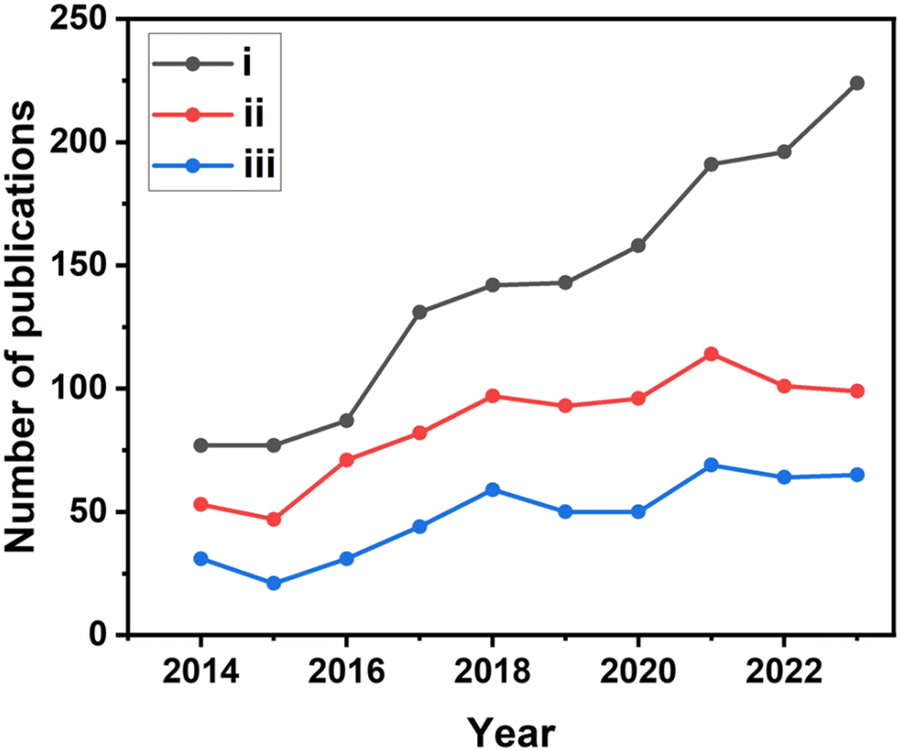 | ||
| Fig. 1 Scopus data-based survey (conducted on February 29, 2024) indicating the number of publications in the area of TiO2-based photocatalytic water splitting for H2 production, with three different sets of keywords, as explained in the text. (i) TiO2, photocatalyst and hydrogen production; (ii) TiO2, photocatalyst and water splitting, and (iii) TiO2, photocatalyst and hydrogen production through water splitting. | ||
Several variations and advances have been made in the past decade, especially regarding TiO2-based semiconductor photocatalysts for solar hydrogen production using water as the main hydrogen source. Therefore, in this review, we comprehensively summarize and highlight the recent progress in the design and structure–activity relation of TiO2-based photocatalysts towards solar hydrogen production with water as the main hydrogen source, where the works employing sacrificial agents are also included to a significant extent. Initially, we provide the fundamental aspects of integrating different materials with TiO2, such as noble metals, non-noble metals, metal oxides/sulphides/selenides, and low bandgap semiconductors and their structure–activity correlation is highlighted to understand the mechanistic aspects and the entire progress in the field of photocatalytic hydrogen production. Also, the role of TiO2-based photocatalysts is specifically reviewed based on the effects of various factors including preparation methods, morphology, crystallographic facet-dependent activity, catalyst loading, and dopant concentration. Subsequently, we discuss the importance of engineering strategies, such as the importance of fabricating photocatalysts in thin film form to overcome the drawbacks of TiO2 in powder form, resulting in improved photoactivity and scalability. Finally, the major challenges and an outlook on the future strategies in this research field are discussed from the viewpoint of the structure–activity relation of various TiO2-based photocatalysts.
2. TiO2-based photocatalytic water splitting processes
The photocatalytic splitting of water to H2 and O2 on the surface of TiO2-based semiconductors proceeds through a redox reaction process, as described in eqn (1)–(3).37| TiO2 + hv → e(CB-TiO2)− + h(VB-TiO2)+ | (1) |
| 2H2O + 4h+ → O2 + 4H+ | (2) |
| 4H+ + 4e− → 2H2 | (3) |
 | ||
| Fig. 2 Flowchart illustrating the fundamental and critical processes involved in semiconductor based photocatalytic water splitting processes. | ||
The bandgap and band position of the photocatalyst,3 the ability of the photocatalyst in enhancing the charge (electron–hole pair) separation and charge diffusion to the redox sites,38–40 presence of sacrificial reagents,41etc. are crucial factors that determine the efficiency of solar hydrogen production. The conversion efficiency of solar energy into hydrogen can be calculated by the apparent quantum yield (AQY) according to eqn (4).42
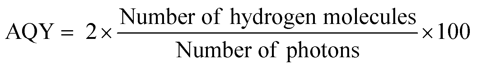 | (4) |
3. TiO2-based water splitting photocatalysts
In the past few decades, significant efforts have been devoted to enhancing the activity of TiO2-based photocatalysts by modifying the band gap, electron–hole separation and charge transfer characteristics of TiO2 by integrating it with different components.42–46 The different types of components used to fabricate electronically integrated TiO2-based photocatalysts include non-metal dopants (S, N, F, and C),15,45,46 metal nanoparticles,47–53 low bandgap metallic oxides (Cu2O, Fe2O3, CeO2−x, NiO, Co2O3, SiO2, and ZnO),6,54–61 metal sulphides (CdS, ZnS, MoS2, FeS2, SnS2, etc.),44,62–65 carbonaceous materials (carbon nanotubes, graphene, reduced graphene oxide (rGO),66–71 graphitic carbon nitride (g-C3N4),72,73 and dye sensitizers).74,75 The integration of the above-mentioned components with TiO2 in the optimum concentration can modify the band gap and electronic structure of pristine TiO2, resulting in improved photocatalytic activity for H2 production.38,39 A schematic representation of the various components used to improve the photocatalytic efficiency of TiO2 is provided in Fig. 3.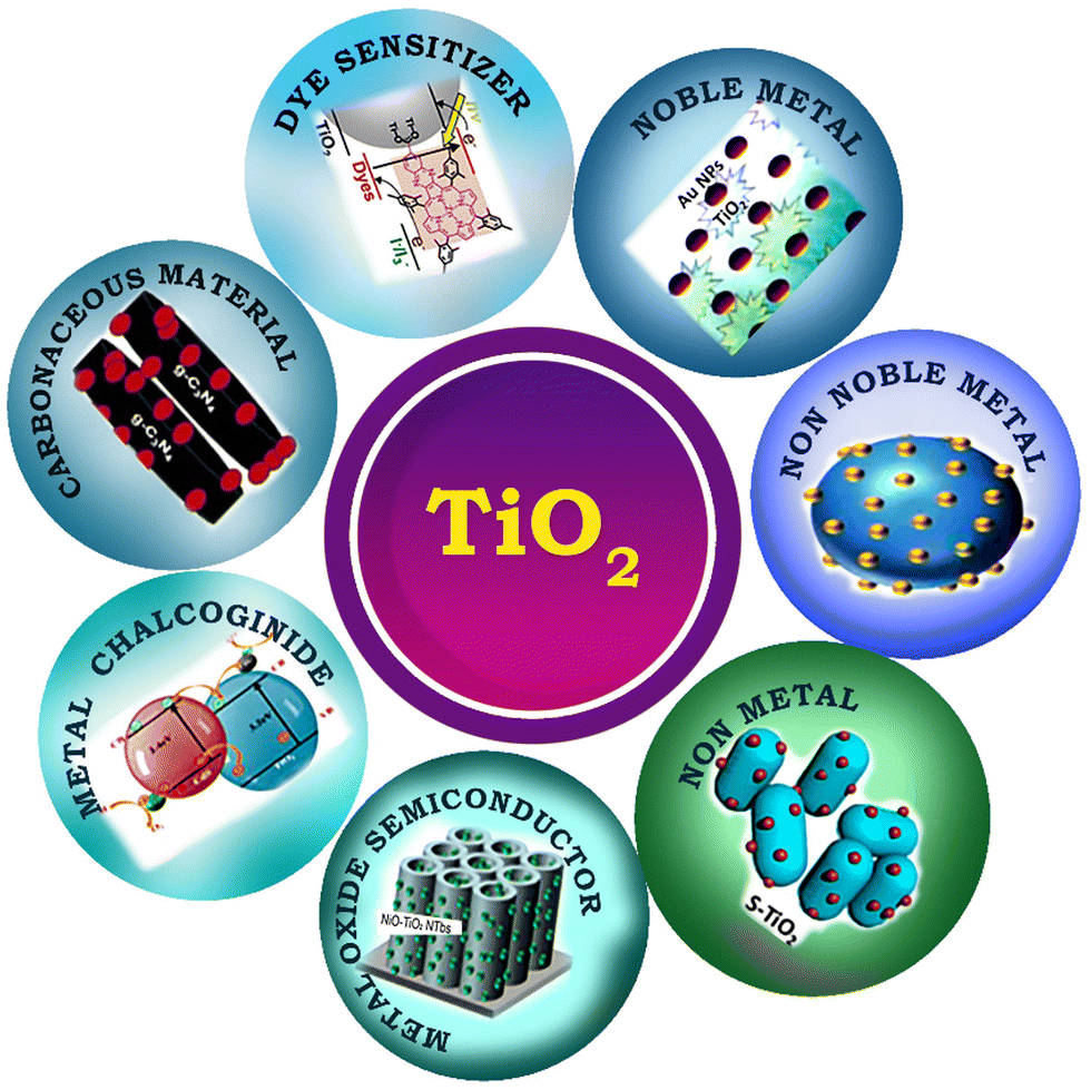 | ||
| Fig. 3 Schematic representation of different types of chemical components used to improve the photocatalytic efficiency of TiO2. | ||
3.1. Metal nanoparticles
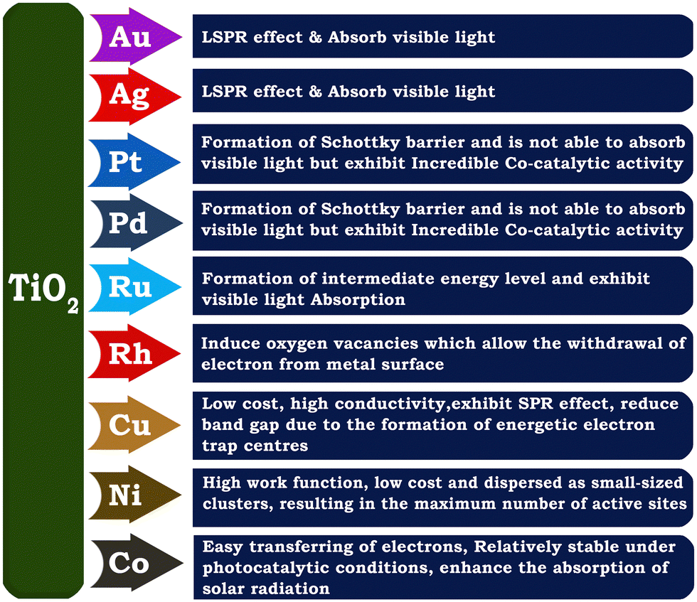
The integration of TiO2 with metal nanoparticles is one of the effective strategies to enhance its electron–hole separation by forming metal–semiconductor Schottky junctions with improved charge transfer efficiency.76 Due to the difference in the Fermi energy levels of metals and TiO2, when they come into contact, photoexcited electrons are transferred from TiO2 to the metal until their Fermi energy levels are equilibrated. The potential of metal nanoparticles as a co-catalyst relies on the ease of electron transfer from the conduction band of TiO2 to the Fermi level of the metallic surface via a Schottky junction. The Schottky junction is formed due to the charge difference between the metal nanoparticles (excess negative charge) and TiO2 surface (excess positive charge), acting as an effective trap for capturing electrons, which can inhibit the recombination of electrons and holes.50,77,78Noble metals including Ru,79 Rh,80 Pd,44,48,81 Au,49,82–84 Ag,85–87 and Pt50,88–90 are widely used as a co-catalyst with TiO2 in photocatalytic hydrogen production due to their unique properties such as formation of a Schottky barrier,43,91 efficient interfacial electron transfer, photostability, ability to show surface plasmon resonance,92 formation of impurity energy levels,79 and oxygen vacancies.80 There are two types of noble metals, plasmonic (Ag and Au) and non-plasmonic (Pt, Pd, Ru, and Rh).48,76 In this case, a Schottky barrier is more critical for non-plasmonic metals such as Pt and Pd, which functions as an effective electron trap, imparting a high density of states to the Fermi level and facilitating charge separation and utilization. For example, non-plasmonic noble metals are not capable of exhibiting visible light absorption; however, they show very high cocatalyst activity.66,76 Noble metals such as Au and Ag on the surface of TiO2 increase the photon absorption in the visible region through the localised surface plasmon resonance (LSPR) effect.93,94 The surface plasmon resonance (SPR) effect increases the production of hot electrons at the interface between the metal and TiO2. Given that the SPR level of the metal is higher than the conduction band of TiO2, electrons are transferred from the SPR level of the metal to the conduction band of TiO2. At the same time, the Schottky barrier can prevent the back transfer of electrons to metal nanoparticles.49 The formation of an intermediate energy level enables charge separation in Ru and extends the light absorption to the visible region,79 whereas Rh induces the generation of oxygen vacancies in TiO2, which allows the withdrawal of electrons from the metal, leading to an enhancement in hydrogen production activity.80 A schematic illustration of the LSPR effect occurring on the surface of a plasmonic metal nanoparticle and H2 production augmented by electron transfer via the Schottky barrier at the interface between a metal semiconductor, such as Au nanoparticle, is shown in Fig. 4(a and b).
 | ||
| Fig. 4 (a) Schematic representation of LSPR effect showing the oscillation of an electric field of incident light at the resonance frequency on the surface of an Au nanoparticle. (b) Schematic diagram of the proposed mechanism for photocatalytic H2 production from ethanol/water mixtures over Au/P25 TiO2. Reproduced with permission from ref. 92. Copyright©2015, Wiley-VCH. | ||
Although noble metals are highly efficient as co-catalysts for photocatalytic hydrogen generation, their high cost and low abundance limit their application, leading to the investigation of earth abundant and cheap non-noble metals co-catalysts.95–97 Non-noble metal nanoparticles such as Cu and Ni as co-catalysts with TiO2 have been found to be highly effective in enhancing the rate of hydrogen production in the water splitting reaction.16,98–102 Heterogeneous surface-distributed non-noble metal nanoparticles on TiO2 increase charge separation and facilitate charge transfer.103 Copper is one of the most studied non-noble metal cocatalysts for solar hydrogen evolution because of its low cost, high conductivity, capability to show SPR effect, etc. The presence of metallic copper substantially changes the electronic structure of TiO2 because of the formation of structural defects or energetic electron trap centres, which prevents electron–hole recombination.95,98,104 Nickel is another attractive non-noble metal co-catalyst because of its high work function, availability and low cost. The high work function of Ni is favourable for preventing the migration of electrons back into the conduction band of TiO2 in Ni/TiO2.105 Metallic Ni nanoparticles dispersed on TiO2 as small-sized clusters resulted in an improved photocatalytic hydrogen evolution rate.105 A schematic description of the properties related to various metal nanoparticles employed for fabricating metal-integrated TiO2 photocatalyst systems for photocatalytic H2 production is provided in Fig. 5.
 | ||
| Fig. 5 Schematic representation of various noble metals used for improving the photocatalytic hydrogen evolution activity of TiO2. | ||
3.2. Bimetallic co-catalysts
Compared to single metallic components, bimetallic cocatalysts provide more active sites for H2 production. The combined effect and the possible synergistic interaction between the two components in a bimetallic system effectively improve the charge separation and charge transfer, where when one of the bimetallic component is SPR active, it also enhances the light absorption capability.18,99 For example, Cu/Ag bimetallic quantum dots on TiO2 nanotubes were shown to be beneficial for solar hydrogen generation, possessing the advantage of the SPR effect of Cu and Ag and co-catalyst capability of Cu.99 A schematic representation of the synthesis of the bimetallic Cu/Ag@TiO2 nanocomposite and its charge transfer mechanism is provided in Fig. 6. | ||
| Fig. 6 (a) Schematic synthesis of Cu/Ag bimetallic deposition on titanium nanotubes (TNTs) and (b) charge separation and hydrogen evolution mechanism of as-synthesized Cu/Ag@TiO2. Reproduced with permission from ref. 99. Copyright©2017, Elsevier Ltd. | ||
Similarly, NiCu alloy was also found to enhance the solar hydrogen production with a quasi-artificial leaf device (QuAL) fabricated using Mn-doped CdS integrated with mesoporous TiO2.106 Mn-doping in CdS was shown to enhance the visible light absorption to a longer wavelength compared to virgin CdS. In the presence of the NiCu-alloy co-catalyst, the QuAL device with an area of 1 cm2 was demonstrated to produce 10.5 mL h−1 of H2 with a power conversion efficiency of 4.8%. Another interesting aspect of this QuAL device is the increase in the visible light absorption efficiency due to different-size integrated Mn-CdS, which exhibited a wide range of band-gap values due to the different QD sizes. The fluorescence is emitted from the smaller QDs and apparently absorbed by the significantly larger QDs or the same Mn-CdS nanoparticles.
3.3. Non-metal doping
Doping TiO2 using non-metals such as S,45 C,15 F,46 and N107 leads to the lowering of its bandgap and is an effective approach to enhance its visible light absorption capability and solar hydrogen evolution.15,108 The addition of non-metal dopants in the TiO2 matrix may generate structural defects in the material, impurity energy level formation, and hence narrowing of the band gap, and also beneficial for overcoming the disadvantages such as carrier trapping and thermal instability that are often encountered with metal nanoparticles.109–112 Nitrogen is one of the most studied anion dopant because of several advantageous aspects, such as its similar atomic size with oxygen, formation of metastable energy states and considerable overlap of the N 2p and O 2p states, resulting in bandgap narrowing and smooth excitation of electrons between the valence band and conduction band.113,114Fig. 7 demonstrates that in comparison to pure TiO2, the optical properties, valence band characteristics, and band positions of N-doped TiO2 samples are modified.115 Further, N-doped samples exhibited an increased in charge separation and charge carrier density compared to pure TiO2. | ||
| Fig. 7 (a) UV-vis absorbance spectra and (b) Tauc plot obtained from the reflectance spectra and (c) valence band edge analysis of TiO2, N-TiO2-450, N-TiO2-550. (d) Proposed band diagrams of TiO2 and N-doped TiO2 catalysts. Reproduced with permission from ref. 115. Copyright©2016, Elsevier Ltd. | ||
3.4. Integration with low band gap semiconductors
The formation of TiO2-based composites with semiconductors having a low band gap is another efficient strategy for enhancing the rate of photocatalytic hydrogen production. Low band gap semiconductors include both metal oxides and metal chalcogenides. Based on the band position of TiO2, semiconductors can be classified into two types, i.e., semiconductor having a more negative CB position than TiO2 (e.g., Cu2O,6,116 CuO,117–119 CeO2,55 ZnO,59 CuInS2,120 CdS,62,121,122 and SnS265), and semiconductor having less negative CB positions than TiO2 (e.g., NiSe,20 FeS2,64 Cu2S,6 and MoS263). A plot of the band positions of TiO2 and various semiconductors against their redox potentials is depicted in Fig. 8.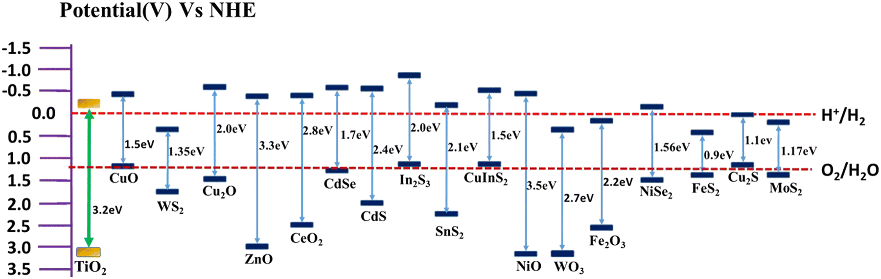 | ||
| Fig. 8 Plot of band positions of semiconductors against redox potential at pH = 7. | ||
The electron hole separation and electron transfer process through the formation of a heterojunction with a low band gap semiconductor depend on the band position of both TiO2 and the supporting semiconductor. If the CB edge potential of the supporting semiconductor is more negative than that of TiO2, the photogenerated electrons in the conduction band of the semiconductor usually transfer to the lower-lying conduction band of TiO2.54,55,123 In contrast, the CB edge potential of the supporting semiconductor is less negative than that of TiO2, and the electrons from the conduction band of TiO2 will be transferred to the lower-lying conduction band of the supporting semiconductor.20,63,124,125
 | ||
| Fig. 9 Schematic representation of various metal oxides used for improving the photocatalytic hydrogen evolution activity of TiO2. | ||
The activity of TiO2 can be further improved by surface modification with Ni (metal) and P (nonmetal), resulting in more effective heterojunctions.55 For example, after surface decoration with Ni–P, the CeO2–TiO2 photocatalyst became an effective photocatalyst for hydrogen evolution due to the lowering of its bandgap to 2.4 eV and powerful electron–hole separation.55 In this photocatalyst, Ni–P acts as a bridge for electron transportation. Also, SiO2 is an interesting substrate used for dispersing and maintaining the active phase, imparting thermal stability and improving the surface area of TiO2-based photocatalysts.58 For example, the pore channels of SiO2 were successfully utilized for anchoring TiO2 quantum dots (TiO2-QDs) in a highly dispersed state on the surface of silica via the in situ hydrolysis of Ti-alkoxide.58 The anchoring effect between TiO2-QDs and the pore-wall of SiO2 foam provided extra stability to TiO2-QDs, which helped in maintaining TiO2-QDs in the anatase phase without undergoing any phase transformation and particle growth even after exposure to high temperature of up to 1000 °C.
NiO is a p-type semiconductor with a bandgap of 3.5 eV, which possesses high charge carrier concentration and high mobility of charge carriers. It can form an efficient p–n heterojunction with anatase TiO2, which facilitates the red shifting of the bandgap energy of the NiO/TiO2 heterostructure.123 The internal electric field developed at the interface of the NiO/anatase TiO2 p–n heterojunctions facilitates the dissociation efficiency of photogenerated electron–hole pairs and enhances the photocatalytic efficiency. For example, mesoporous heterostructure of 1 wt% NiO on anatase TiO2 nanoparticulate photocatalyst showed an H2 production rate of 2693 μmol h−1 g−1 by methanol photo-reforming, which is higher than that of pure anatase TiO2 and commercial P25.
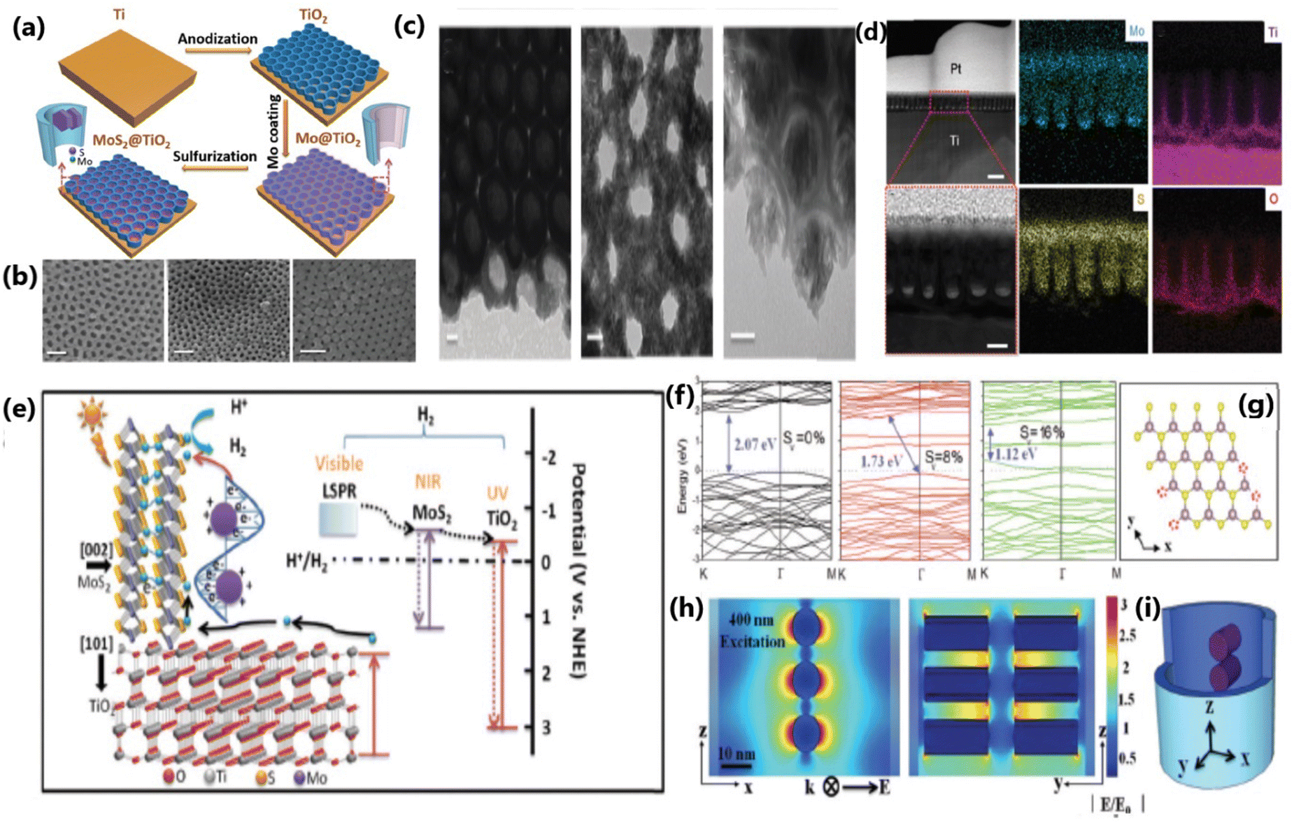 | ||
| Fig. 10 (a) Schematic illustration of the assembly process of the MoS2@TiO2 heterostructure. (b) SEM pictures of MoS2(10)@TiO2, MoS2(20)@TiO2 and MoS2(30)@TiO2, respectively (scale bar: 100 nm). (c) TEM and HRTEM images of MoS2(10)@TiO2 and MoS2(20)@TiO2 (scale bar: 20 nm). (d) Cross-sectional HAADF-STEM images and EDS elemental mapping of the MoS2@TiO2 heterostructure (first row, scale bar: 200 nm, and second row, scale bar: 50 nm). (e) Schematic diagram of the energy band structure, plasmonic resonance and electron transfer pathway in the MoS2@TiO2 heterojunction. (f) Band structure of monolayer 2H-MoS2 with 0%, 8% and 16% S-vacancies, with the valence band maximum and conduction band minimum both at the K point. (g) Model used for band gap computation via DFT. (h) FEM simulation of the near-field electric field distribution inside MoS2@TiO2 heterostructures excited by a 400 nm laser and (i) 3D-simplified model used for FEM simulation. Reproduced with permission from ref. 139. Copyright ©2018, The Royal Society of Chemistry. | ||
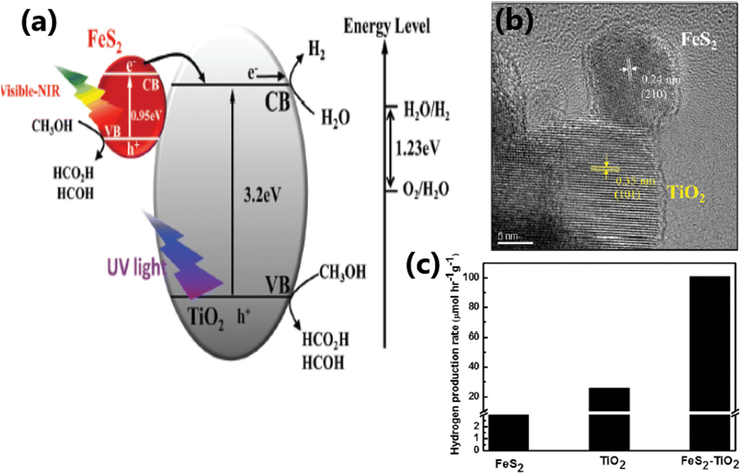 | ||
| Fig. 11 (a) Schematic illustration of the interfacial charge transfer process in FeS2–TiO2 catalyst under UV, visible and near-IR light irradiation. (b) HRTEM image showing the intimate contact between the (210) plane of FeS2 and the (101 plane) of TiO2 in FeS2–TiO2. (c) Rate of hydrogen evolution from TiO2, FeS2 and the FeS2–TiO2 nanocomposite under a 300 W xenon lamp. Reproduced with permission from ref. 64. Copyright ©2018, the Royal Society of Chemistry. | ||
3.5. Carbon-based photocatalytic materials
The combination of TiO2 with carbonaceous materials such as graphene,70,140 graphene oxide,66,141,142 carbon nanotubes (CNTs)67 and graphitic carbon nitride (g-C3N4)143–146 leads to highly promising heterostructures for photocatalytic hydrogen generation, in addition to mechanical strength. A study70 reported a rough estimate of the weight ratio of TiO2 to RGO of around 105–106; nonetheless, the RGO layers seem to be intact without any faults. These composite materials were effective in preventing the agglomeration of metal nanoparticles and displayed good light absorption capacity and electron–hole separation.147 The two-dimensional (2D) carbonaceous materials reported in the literature to enhance the rate of photocatalytic H2 production of TiO2 nanocomposites include graphene,148 reduced graphene oxide,149 and g-C3N4.68,144,150,151 The excellent physical, chemical and photocatalytic properties of these TiO2-2D carbonaceous materials, such as high specific surface area, high mechanical and chemical stability, outstanding visible light absorption ability, high electrical conductivity and charge carrier mobility, ability to shuttle charges between the composite material and regain its sp2 hybridised structure, spatial charge separation of electron–hole pairs, reduced band gap and good charge separation make them highly promising photocatalytic materials.67,68 The enhanced photocatalytic activity and H2 production ability of CNT/TiO2 composite materials are due to the significant electron transport and optical properties of CNT and creation of an intermediate energy level, which help to improve the visible light absorption capacity of the material.67,68,152Fig. 12 illustrates the synthesis protocol for fabricating TiO2/g-C3N4 nanosheet composites, detailing their optical absorption properties, morphology, photocatalytic hydrogen evolution mechanism, and valence band characteristics. | ||
| Fig. 12 (a) Schematic illustration of the synthesis of TCNx composites. (b) UV-vis absorption spectra of TiO2 and TCNx composites. SEM images of (c) g-C3N4 NS and (d) TCN50. (e) and (f) HRTEM images of TCN50. (g) Proposed mechanism for visible light photocatalytic activities of TCNx composites. (h) VB XPS of TiO2 and g-C3N4 NS. Reproduced with permission from ref. 151. Copyright ©2017, the Royal Society of Chemistry. | ||
3.6. Dye sensitization
Dye sensitization is a simple and effective technique to improve the visible light-harvesting capacity,17,153 and thereby the photocatalytic hydrogen production activity of materials. Amongst the different dye sensitizers, organometallic complexes17 and metal-free organic dyes154 are the most widely used and TiO2 in combination with them display enhanced photocatalytic hydrogen production.155 During photocatalysis, the electrons from the lowest unoccupied molecular orbital of the sensitized dye are injected into the conduction band of TiO2, leading to the efficient separation of electrons and holes. In comparison with dye-sensitized TiO2, bare TiO2 shows poor solar light conversion efficiency.100 Dyes used for sensitization, especially organic dyes, may degrade with time as a result of exposure to light, changes in temperature, or chemical interactions with the environment. As a result of this deterioration, the overall stability and effectiveness of the photocatalytic system may decrease. In certain cases, the photochemical stability of dyes may be enhanced if the dye and semiconductor are connected by a covalent bond rather than a weak interaction.156 A diagrammatic illustration of the dye sensitization and the hydrogen evolution mechanism of Eosin Y-sensitized C-TiO2 hollow nanoshell system is presented in Fig. 13.155 | ||
| Fig. 13 Mechanism for photocatalytic H2 evolution over eosin Y-sensitized C-TiO2 hollow nanoshells with Mie resonance. Reproduced with permission from ref. 74. Copyright ©2021, Elsevier Ltd. | ||
3.7. TiO2-based ternary composite material
The construction of structurally organized ternary nanocomposites with efficient heterojunctions through their intimate contact is a versatile approach to improve the photocatalytic performance and hydrogen yield of the water splitting reaction. Different types of ternary composite systems with superior catalytic performance compared to the corresponding binary composites have been reported in the literature, which include Au–Pd/rGO/TiO2,66 Au/(TiO2–g-C3N4),157,158 Pt/Cu/TiO2,117 GO/TiO2/ZnIn2S4,142 CuInS2/TiO2/MoS2,120 CuO–Co3O4/TiO2,159 Pd–SrIn2O4–TiO2,160 CuS–TiO2/Pt,161 and Cu2O/TiO2/Bi2O3.162 The different hydrogen generation activities reported for the same/similar catalysts from the above-mentioned references suggest that the quality of heterojunctions is different, which may be one of the main reasons for efficient charge separation and migration to the redox sites. For example, the superior activity of the Au/(TiO2-gC3N4) ternary composite is due to the efficient charge separation and enhanced visible light absorption in a wide wavelength range resulting from the SPR effect of Au nanoparticles and the potential to shuttle electrons using g-C3N4.157,163 The photocatalytic performance of TiO2 can be enormously improved by creating a triple composite CuInS2/TiO2/MoS2, which exhibit a huge absorption range from the UV region to the near-infrared region.120 On irradiation, the excited electron from CuInS2 is smoothly transferred via TiO2 to MoS2, where the adsorbed proton is reduced to H2.120 The metal nanoparticles in ternary composites act as an effective co-catalyst and further enhance the rate of hydrogen generation by supplying electrons and active sites.66,157,160Fig. 14 shows a schematic illustration of the electron transfer mechanism and photocatalytic H2 production over an Au–Pd/rGO/TiO2 triple composite, wherein the SPR-induced electron is directly transferred from Au to the CB of TiO2via rGO.66Table 1 lists a detailed comparison of the H2 yield and the corresponding experimental conditions for some TiO2-based photocatalysts. | ||
| Fig. 14 Schematic illustration of the mechanism of photocatalytic hydrogen evolution from an Au–Pd/rGO/TiO2 triple composite, in which an SPR electron from Au is transferred to TiO2via rGO. Reproduced with permission from ref. 66. Copyright ©2019, ACS. | ||
| No. | Material | Experimental conditions | H2 yield/mmol h−1 g−1 | Ref. |
|---|---|---|---|---|
| Metal-integrated TiO2 | ||||
| 1 | 0.5Rh/TSG (TiO2 sol–gel) | 50 mg of 0.5Rh/TSG photocatalyst in aqueous solution of ethanol (50% v/v, water), UV Pen-Ray Hg lamp (λ = 365 nm) | 7.2246 | 51 |
| 2 | Ru 8.0/TiO2 NBs-400 | 10 mg of photocatalyst was suspended in 10 mL of water containing 0.1 g of ethylenediamine tetra acetic acid disodium salt (EDTA-2Na), 300 W xenon lamp | 25.34 | 47 |
| 3 | TiO2Ag-F | 200 mg catalyst in 200 mL of distilled water, 4 mL of methanol, 250 W mercury lamp | 0.180 in 4 h | 38 |
| 4 | TiO2–Au-1% Pt | 10 mg of TiO2–Au photocatalyst into an aqueous methanol solution (120 mL, 25 vol%), 300 W Xe Lamp UV cut-420 nm filter | 0.0924 | 49 |
| 5 | 3 wt% Au/P25 TiO2 | (6.5 mg) was placed in ethanol (15 mL) and Milli-Q water (3.75 mL), 200 W, 365 nm with 6.5 mW cm2 | 31.5 | 92 |
| 6 | Ag@TiO2 | 0.05 g catalyst was suspended in deionized water and methanol mixed solutions (40 mL, 3![[thin space (1/6-em)]](https://www.rsc.org/images/entities/char_2009.gif) :1), 300 W xenon lamp :1), 300 W xenon lamp |
0.5319 | 164 |
| 7 | Pd/P25 1 wt% of Pd | Thin film forms of photocatalysts (1 mg) with 25% v/v aqueous methanol solution, direct sunlight 50.2 mW cm−2 | 104 | 165 |
| 8 | Au(2%)@TiO2 | 15 mg of photocatalyst was dispersed in 25 mL total volume containing 20% methanol (v/v) in aqueous solution, natural sunlight | 3.99 μmol h−1 with 100 mg | 166 |
| 9 | The TiO2–Pd NSs | 15 mg photocatalyst was dispersed in 50 mL of methanol/H2O mixture (20 vol% methanol), 300 W Xe UV lamp and vis-NIR light were used as illumination source, 400 nm cutoff filter 2.7 and 100 mW cm−2 | 2.80 | 167 |
| 10 | Au@TNT | 50 mg of photocatalyst was added to 100 mL of methanol-deionized water mixed solution (VMeOH/VH2O = 1:10), Xe lamp (λ > 400 nm), intensity of incident visible light (400 nm) was 0.1 W cm−2 |
0.482 | 168 |
| 11 | 1.5% Ag/TiO2 | 20% (v/v) aqueous solution of Na2S + Na2SO3, 254 nm wavelength UV light, intensity of light was 4.40 mW cm−2 | 23.496 | 112 |
| 12 | TiO2–Au 9 wt% | 30 mg of catalyst was dispersed in 150 mL of water/methanol mixture with the volume ratio of 9:1, 300 W xenon arc lamp intensity was 380 mW cm−2 |
12.440 | 169 |
| 13 | Pd/TiO2 nanosheets (0.18 At% Pd NPs) | 50 mg of photocatalyst in 50 mL of an aqueous solution containing 20% methanol in volume, 300 W Xe lamp equipped with a cut-off filter i (λ > 420 nm), light intensity (50 mW cm−2) | 3.096 | 170 |
| 14 | 0.1 mol% Ru–TiO2 | 0.5 g of fine powder photocatalyst was suspended in 550 mL water and 50 mL methanol, 500 W Hg mid-pressure immersion lamp λ > 320 nm | 3.400 | 79 |
| 15 | 1 wt% Ag/TiO2(TiAg-1) | 1 mg photocatalyst was dispersed in 1 mL ethanol drop-casted on a thin film, 25% (v/v) methanol/water mixture, direct sunlight | 4.59 | 43 |
| 16 | TiO2/Cu | 20 mg of TiO2 and a given amount of metal particles were added to 30 mL, 15 W black light with emission of ∼352 nm; 1.0 mW cm−2 | 0.850 mmol g−1 in 3 h | 171 |
| 17 | Cu/Ag@TNT 0.1 M Cu and 0.1 M Ag | 5 mg of catalyst was dispersed in 50 mL of 5 vol% glycerol aqueous solution, 300 W Xe lamp with a UV cutoff filter with wavelength of >400 nm | 56.167 | 99 |
| 18 | TiO2–Ni-1% | 50 mg photocatalyst was added to methanol solution (20 vol%), 300 W Xe lamp | 1.433 | 16 |
| 19 | Cu(3%)–TiO2/ErB | 5 mg of catalyst in 70 mL water containing 10 vol% triethanolamine, 300 W Xe lamp 0.15 W cm−2 | 13.4 | 104 |
| 20 | 0.5 wt% Ni/P25 TiO2 | Photocatalyst (6.5 mg) was placed in the reactor and 20 mL of an aqueous glycerol mixture (10 vol%), 100 W, 365 nm at a distance of 10 cm from the reactor. The photon flux at the sample was 6.5 mW cm−2 | 26.0 | 101 |
| 21 | Ni-a/TiO20.46 wt% | 50 mg of the sample disperses in 100 mL of 10 vol% methanol aqueous solution, 300 W Xe lamp | 0.0945 mmol h−1 with 50 mg | 172 |
| 22 | TiO2–NT/Pd–ND | 1 mg catalyst in H2O/MeOH solution (2:1), 300 W Xe lamp, maximum intensity of 203.3 mW cm−2 at wavelength of 365 nm |
0.143 mmol h−1 with 1 mg | 173 |
| TiO2 with non-metals | ||||
| 23 | 15 wt% S-modified TiO2/β-SiC | 0.05 g of catalyst was suspended in 50 mL of an aqueous solution containing 10 vol% of methanol solution, 125 W medium pressure Hg visible lamp was used, 1 M NaNO2 solution as a UV filter under visible light irradiation (λ ≥ 400 nm) | 1.254 | 45 |
| 24 | N-doped TiO2 hollow fibres nitrogen up to 5 at% (N-TiO2) | Photocatalyst sample (0.02 g) was immersed in an aqueous methanol solution (5 mL methanol and 20 mL deionized water), 150 W Xe lamp optical filter, which allowed only wavelengths higher than 420 nm | 0.185 μmol g−1 in 6 h | 108 |
| 25 | TiO2/C | 5 mg catalyst powder in aqueous solution (10 mL) consisting of triethanolamine (10 vol%), 300 W Xe lamp, cut-off filter (λ > 400 nm) | 57.2 μmol h−1 with 5 mg | 174 |
| TiO2 with metal oxide semiconductor | ||||
| 26 | 5 wt% Fe2O3/TiO2 | 50 mg Fe2O3/TiO2 nanocomposite was suspended with magnetic stirring in 200 mL aqueous solution 10 vol% glycerol, 500 W Xenon lamp with UV cutoff filter (λ > 420 nm) | 1.0 mmol h−1 g−1 | 54 |
| 27 | Ni–P/CeO2–TiO2 | 0.5 g of the prepared catalyst was directly dispersed in 20 mL deionized water, 1 Sun (1000 mW cm−2) was applied by a solar simulator | 1.30 mmol in 5 h with 0.5 g | 55 |
| 28 | Pt/NiO–TiO2 | 0.1 g of catalyst was suspended in water + methanol mixtures (33% v/v, 15 ml), 400 nm, λmax = 536 nm (medium-pressure Hg lamp, 400 W) and UV-vis light source (Hg lamp, 400 W) | 0.537 mmol g−1 h−1 | 56 |
| 29 | TiO2-QDs/SiO2 | 50.0 mg of TiO2/SiO2 composite photocatalyst was suspended in 80.0 mL of aqueous solution containing methanol (25.0 vol%), UV-LEDs (3 W, 365 nm) | 10.399 mmol g−1 h−1 | 58 |
| 30 | TiO2–ZnO-(0.6%) | 30 mg catalyst powder was ultrasonically dispersed into 80 mL H2O, and then 20 mL methanol, 300 W Xe lamp, the light intensity was kept at around 244 mW cm−2 | 0.3135 mmol h−1 with 30 mg | 59 |
| 31 | 2.82 wt% Ag2O·TiO2 | 0.2 g catalyst was suspended in 100 mL glycerol aqueous solution (with 7 vol% of glycerol), 300 W Xe arc lamp (320–780 nm) | 336.7 μmol h−1 g−1 | 131 |
| 32 | 1 wt% NiO/anatase TiO2 | (50 mg) and the mixture of methanol/H2O (1:1 v:v, 10 mL), UV-light (Hg vapor light source (LUMATEC SUPERLITE 400)) |
2.693 | 123 |
| 33 | 25 wt% of Y2O3 in TiO2 | Photocatalyst (10 mg) was dispersed in a 7.5 mL aqueous solution. After sonication, 2.5 mL ethanol was added as a sacrificial reagent, 300 W Xenon/Mercury lamp | 1.380 in 2.5 h | 124 |
| 34 | 1 wt% Cu/TiO2 | Photocatalyst (2.5 mg) was loaded in the reactor containing 25 mL of a glycerol–water mixture (5 vol% glycerol), 100 W, 365 nm UV light, excitation at ∼6.5 mW cm−2 | 15.32 | 175 |
| 35 | 2.5-Cu2O/TiO2 | 450 mL aqueous solution, 10 vol% ethylene glycol as a scavenger in reaction solution, 500 W Xe arc lamp bandpass filter (λ = 365 nm with the photon flux of 3.6 mW cm−2) | 2.048 | 176 |
| 36 | TiO2–(0.1 wt%)CuO | 0.1 g of the sample was suspended in 1 M KOH, 300 W xenon lamp | 2.715 in 5 h | 177 |
| 37 | Cu2O/TiO2 | 0.1 g of the Cu2O/TiO2 photocatalyst was dispersed in 100 mL 10 vol% aqueous methanol, 300 W xenon lamp with or without a bandpass filter (λ > 420 nm) | 24.83 | 178 |
| TiO2 with metal chalcogenides | ||||
| 38 | S-doped hetero nanostructured TiO2/Cu2S | Aqueous solution containing 0.35 M Na2SO3 and 0.35 M Na2S, visible light irradiation conditions (λ > 420 nm) | 1.280 with 50 mg | 6 |
| 39 | NiSe/TiO2 | 50 mg of the as-prepared photocatalyst powder in 100 mL aqueous solution containing 10 vol% methanol | 55.4 μmol h−1 | 20 |
| 40 | FeS2–TiO2 | 1 g catalyst (50% aqueous methanol solution), mercury arc lamp (400 W) | 0.331 | 64 |
| 41 | MoS2/TiO2 (0.14 wt%) | 50 mg photocatalyst was suspended in 80 mL solution containing 20 mL methanol, four low-power LEDs (3.5 W cm−2, λ = 365 nm) | 2.443 | 125 |
| 42 | 10 mmol NiS/TiO2 nanosheet films | 80 mL 10% ethanol/H2O (v/v) solution, 500 W Xe lamp | 4.31 μmol cm−2 in 3 h | 135 |
| 43 | MoS2/TiO2 | MoS2@TiO2 films with a size 7 × 7 mm were submerged in 15 mL of mixed solution made of DI water (seawater) and methanol (8:2 by volume), solar light simulator (AM 1.5, 300 W Xe, 100 mW cm−2) |
580 | 139 |
| 44 | 0.50 wt% MoS2, 2D-2D MoS2/TiO2 | 100 mg photocatalyst in 100 mL aqueous solution containing 10% methanol in volume, 300 W Xe-arc lamp | 2.145 | 137 |
| 45 | 2D/1D TiO2 nanosheet/CdS nanorods | 50 mg photocatalyst was suspended in aqueous solution (20 mL lactic acid, 210 mL water), 300 W Xenon arc light source after filtering the UV light with circulating cooling NaNO2 aqueous solution (1 M) to pass only visible light (λ > 400 nm) | 128.3 | 179 |
| TiO2 with carbonaceous material | ||||
| 46 | g-C3N4-TiO2 (1:4) |
75 mg of photocatalyst was dispersed in 75 mL of aqueous solution containing 10% triethanolamine, 250 W visible light source | 1.041 | 68 |
| 47 | TiO2-100-G | Photocatalyst (100 mg) was dispersed in an aqueous solution containing H2O (80 mL) and CH3OH (20 mL), 300 W Hg lamp with a wavelength of approximately 365 nm | 1.93 | 180 |
| 48 | TiO2/g-C3N4 | 15 mg sample dispersed in 8 mL ethanol and 72 mL H2O, 150 W Xenon lamp with a cutoff filter (λ > 420 nm) | 0.35 | 181 |
| TiO2 with dye sensitization | ||||
| 49 | C-TiO2 hollow nanoshells with Eosin Y sensitization | Under visible light irradiation (λ > 420 nm) | 0.468 | 74 |
| 50 | Ru(dcbpy)3/TiO2 | 50 mL of solution containing 20 mg of photocatalyst and EDTA (2 mmol L−1), irradiated by a xenon lamp (150 W) with a UV cutoff filter (λ > 400 nm) | 94 μmol g−1 in 5 h | 17 |
| 51 | Carbazole-based organic dye-sensitized Nafion-coated Pt/TiO2 system (D1@NPT) | 20 mL aqueous suspension containing 10 mg of the photocatalyst and 10 vol% of TEOA as SED, Xenon arc lamp (400 W) was used as a light source | 67.9 μmol h−1 | 154 |
| 52 | BE-Au(1 wt%)-TiO2(modified poly(benzothiadiazole) flake denoted as BE) | 30 mg catalyst was dispersed in 30 mL 10% vol TEOA aqueous solution, filters (λ = 420, 500 nm, etc.) are used | 781.2 μmol h−1–30 mg | 182 |
| TiO2-ternary composite material | ||||
| 53 | Au–Pd/rGO/TiO2 | 25 mg of the catalyst was suspended in 40 mL of an aqueous methanol solution (25% v/v), (300 W xenon arc lamp) with AM 1.5 filter under 1 sun conditions (100 mW cm−2) | 21.50 | 66 |
| 54 | Pt0.5–Au1/TiO2 | (20 mg) of catalyst was added to 30 mL of distilled water and 10 mL methanol, 300 W power AM1.5 (100 mW cm−2) or >400 nm (92 mW cm−2) filter | 1.275 | 76 |
| 55 | 0.5 wt% Pt/0.1 wt% Cu/TiO2 | 20 vol% methanol–water, photocatalyst powder (14 mg) was mixed with distilled water (1.2 mL), deposited on 0.85–0.42 mm quartz beads (3 g), xenon arc lamp, 300 W, 40.0 mW cm−2 irradiation intensity | 27.2 | 117 |
| 56 | CuInS2/TiO2/MoS2 photocatalyst with 0.6 mmol g−1 CuInS2 and 0.5 wt% MoS2 | 50 mg photocatalyst was suspended in 250 mL of an aqueous solution containing 0.1 M Na2S and 0.1 M Na2SO3, 300 W Xenon lamp equipped with a UV cutoff filter (λ > 420 nm) | 1.034 | 120 |
| 57 | rGO/TiO2/ZIS (2.0 wt% rGO and 50 wt% ZIS) | 0.01 g of sample is added into 10 mL of aqueous solution containing 0.35 M of Na2S and 0.25 M of Na2SO3, with a light source (300 W Xe lamp) | 0.4623 | 142 |
| 58 | 0.5 wt% Au/(TiO2–g-C3N4) (95/5) | 1 L of Milli-Q water and triethanolamine (TEOA) (1 vol%), solar light | 1.750 | 157 |
| 59 | CuO(1%)–Co3O4 (0.05%)/TiO2 | 20 mg photocatalyst was suspended in 100 mL of pure water or methanol aqueous solution (30 vol%), 300 W Xe lamp, light intensity of 600 mW cm−2 | 0.273 with 20 mg | 159 |
| 60 | 2 wt% Cu2O/TiO2/Bi2O3 | 5% glycerol–water solution 0.05 g L−1 photocatalyst, natural solar light | 6.727 with 50 mg | 162 |
| 61 | Pt(0.02%)Co3O4(0.005%)(D)/N-TiO2 (PCNT(D)) | 100 mg of photocatalyst dispersed in 100 mL of an aqueous solution containing methanol (VH2O: VMeOH = 9:1), 300 W Xe lamp and a UV light cutoff filter (λ > 400 nm) with a light intensity of 380 mW cm−2 |
197 | 183 |
4. Factors influencing solar hydrogen generation activity of TiO2
The performance of a photocatalyst and its photocatalytic hydrogen evolution activity depend on the extent of electron and hole photogeneration and large extent of charge separation, followed by charge transfer to the redox sites for redox reactions to occur.133 The use of dopants and/or co-catalysts in suitable combination and composition and their synthesis strategy are crucial to obtaining efficient photocatalysts and various material properties, such as morphology, surface area, particle size, and band gap are beneficial for realizing the maximum performance for solar H2 production.76,123 The critical factors that determine the photocatalytic performance in solar hydrogen evolution on TiO2-based photocatalysts are summarized in Fig. 15.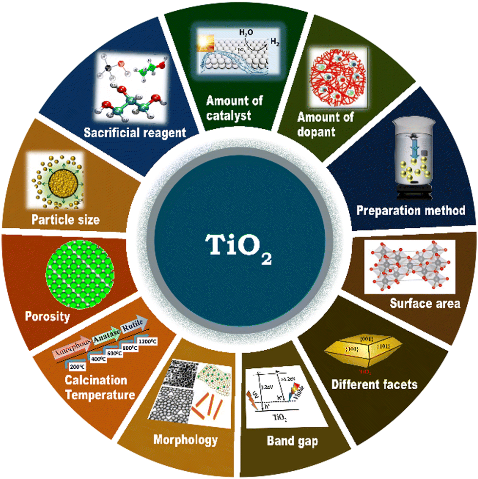 | ||
| Fig. 15 Schematic representation of the various factors that determine the photocatalytic hydrogen evolution activity of TiO2-based photocatalysts. | ||
4.1. Effect of preparation method
The synthesis method largely influences the physical and chemical properties of photocatalysts, which in turn have a huge impact on the rate of solar hydrogen evolution.67,134,184 Accordingly, numerous new synthesis strategies have been developed in recent years for the fabrication of TiO2-based photocatalysts, which include molten salt method,172 impregnation method,67,184 sol–gel (SG) method,184 chemical adsorption decomposition (CAD),184 composite precipitation (CP),184 ionic liquid-assisted hydrothermal method (ILAHM),134 chemical bath deposition process (CBD),9 and electrospinning preparation. A schematic representation of some of the most common synthesis strategies of TiO2-based photocatalytic systems reported in the literature is shown in Fig. 16. | ||
| Fig. 16 Schematic representation of the various strategies for the synthesis of TiO2-based photocatalyst systems reported in the literature. | ||
Li et al. reported six distinct preparation methods for the fabrication of CuO/TiO2 photocatalysts and evaluated the performance of these differently prepared materials in the photocatalytic hydrogen evolution reaction.184 As illustrated in Fig. 17, among the methods, including CAD, CP, impregnation (EI, SWI, and SI) and SG, CuO/TiO2 prepared via the CAD method showed the highest rate of hydrogen evolution (3155.7 μmol g−1 h−1). The highest activity of the material prepared via CAD is due to the formation of TiO2 in the anatase/rutile mixed-phase. The advantages of anatase/rutile mixed-phase include enhanced electron–hole separation, transfer of electrons from rutile to anatase phase, and formation of catalytic hotspots at the interface of the anatase and rutile phases.
 | ||
| Fig. 17 Comparison of the photocatalytic hydrogen evolution rate on pure P25 and CuO/TiO2 samples produced by different preparation methods, namely chemical adsorption decomposition (CAD), composite precipitation (CP), ethanol impregnation (EI), simple wet impregnation (SWI), stepwise impregnation (SI), and sol–gel (SG). Reproduced with permission from ref. 184. Copyright ©2014, Springer. | ||
A comparison of the activity of the TiO2/CuO nanocomposites prepared via the ILHAM, hydrothermal, sol–gel and ionic liquid co-precipitation methods for photocatalytic H2 production was reported, and this study revealed that the TiO2/CuO nanocomposite produced via ILHAM showed the highest hydrogen evolution activity (8.670 mmol g−1 within a period of 2.5 h) under a xenon/mercury lamp using aqueous methanol.134 The highest activity of the TiO2/CuO nanocomposite obtained by the ILAHM method is attributed to the versatility of this synthesis strategy to control the morphology and other physico-chemical characteristics of the catalyst by utilizing the unique properties of ionic liquids such as thermal stability and low vapor pressure.134
A comparison of the photocatalytic activity of mesostructured Ag@TiO2 prepared by the in situ electrospinning method and electrospinning in combination with the photo-deposition approach revealed that Ag@TiO2 nanofibers prepared through the former method displayed a higher H2 yield of 531.9 μmol g−1 h−1 under one sun conditions with 25% aq. methanol.164 The high activity of the Ag@TiO2 nanofibers fabricated via the in situ electrospinning method is attributed to its relatively large BET surface area (39.8 m2 g−1) and smaller particle size (16.5 nm) than that prepared by the other method.164
Xiao et al. developed a new molten salt technique to synthesize atomically dispersed Ni species on TiO2, as illustrated in Fig. 18a for application in photocatalytic water splitting to produce H2, which exhibited 4-times higher activity (94.5 μmol h−1 for 50 mg of sample) than Ni/TiO2 prepared by the conventional impregnation method.172 The experimental and theoretical studies (Fig. 18b–d) revealed that the higher activity of Ni/TiO2 produced by the molten salt technique is due to the fact that it enabled the atomic distribution of Ni ions on TiO2, which favoured the formation of strong Ni–O bond and large number of oxygen vacancies. Consequently, this made the material highly integrated and was beneficial for efficient charge carrier utilization. The chemical bath deposition process is another versatile synthesis strategy employed in the literature for achieving the uniform deposition of metal species on TiO2, as reported by Chang et al., for the fabrication of Cu2O on mesoporous TiO2 beads (MTBs), which facilitated the essential charge separation for an improved hydrogen generation rate (223 mmol h−1 g−1).9
 | ||
| Fig. 18 (a) Schematic illustration of molten salt-mediated preparation of atomic Ni on TiO2. For the TiO2 molecular structure, (b) EXAFS and XANES spectra of Ni/TiO2, respectively. Ni loading amount: 0.46 wt% (c) Comparison of H2 evolution activity on Ni-np/TiO2, Ni-a/TiO2 and Pt/TiO2 with the same loading amount (∼0.5 wt%). Experimental condition: 50 mg of sample dispersed in 100 mL of 10 vol% methanol aqueous solution (278 K) under an irradiation of a 300 W Xe lamp. (d) Free energy versus the reaction coordinates of different active sites. The simulation is based on the (101) facet of anatase TiO2. (e) Molecular models of OV on Ni/TiO2 and the corresponding formation energy of OV. Reproduced with permission from ref. 172. Copyright© 2020, Wiley-VCH. | ||
The synthesis strategy leading to the formation of TiO2 with a sufficient amount of Ti4+ ions in tetrahedral coordination enhances the photocatalytic H2 production rate due to fact that the photocatalytic activity of TiO2-based catalysts depends on the quantity of Ti4+ ions present in a tetrahedral environment.185 Kumari et al. reported an impregnation method for the fabrication of functionalized carbon nanotubes (FCNTs) integrated with TiO2 nanotubes (TiNTs), which showed a high performance (7476 μmol h−1 g−1) for the photocatalytic hydrogen evolution reaction due to the strong interaction between FCNTs and TiNTs and the well-dispersed nature of the catalyst.67
Careful control of the synthesis parameters and process variation are essential given that even a slight variation in the synthesis process may introduce a variety of defects and impurities that could improve or worsen the photocatalytic activity and stability of materials. Generally, anatase-phase TiO2 exhibits higher activity than the rutile phase, but synthesis frequently results in mixed-phase materials, making property optimisation more challenging.
4.2. Effect of surface area
Surface area is a crucial factor that influences the photocatalytic performance of a catalyst. Given that photocatalytic hydrogen generation is a surface-based phenomenon, a catalyst with a high specific surface area can offer more adsorption sites and photocatalytic reaction centers.45 Khore et al. performed a comparative study of the photocatalytic performance of pristine TiO2 and Au@TiO2 photocatalysts for hydrogen generation under natural sunlight and arrived a correlation between their surface area and activity.166 As illustrated in Fig. 19, among the studied catalysts, 2 wt% Au-loaded TiO2 with the highest surface area (60 m2 g−1) showed the highest activity with an H2 yield of 3.99 mmol g−1 h−1, and the activity decreased as the surface area decreased.166 | ||
| Fig. 19 Amount of hydrogen produced vs. surface area of photocatalyst for Au@TiO2:0.5Au-450, 1Au-450, 2Au-450 and 3A-450 under natural solar light. Adopted from ref. 166. Copyright ©2018, the Royal Society of Chemistry. | ||
In another variation, among different TiO2-NT (nanotube)-based photocatalysts (TiO2-NT, TiO2-NT/ZnO-NR (nanorod), TiO2-NT/ZnO-NR/Ag-NP (nanoparticle), TiO2-NT(nanotube)/Pd-NDs (nanodendrites)) employed for photocatalytic H2 production under one sun conditions using an H2O/MeOH (1:2) mixture, the TiO2-NT(nanotube)/Pd-ND catalyst having the highest surface area showed the highest hydrogen generation rate of 143.1 μmol h−1.173 Mishra et al. synthesized 15 wt% S-modified TiO2/β-SiC and showed that the high photocatalytic hydrogen evolution activity of the catalyst is due to its high specific surface area.45
A 2D TiO2/g-C3N4 photocatalyst with 20 wt% TiO2 having a high specific surface area showed a 2.4-times higher photocatalytic hydrogen evolution rate than g-C3N4 nanosheets having a relatively low specific surface area. The high photocatalytic activity of 2D TiO2/g-C3N4 is due to its high surface area, and hence higher number of available active sites for hydrogen production.181 Another way of utilizing the advantage of the high surface area in improving the photocatalytic H2 production rate of titania is by modifying it in the form of silica-embedded titania and/or titania silica mixed oxide.87 Although the correlation between surface area and photocatalytic activity has been demonstrated in the literature, there are some reports showing that surface area hardly had any influence on the photocatalytic activity and H2 production rate in comparison with other favourable factors, as illustrated in the case of CuO/TiO2 heterojunction and Pt@CuO/TiO2 composites synthesized employing TiO2 nanosheets and nanorod precursors.186 Further, a high surface area is invariably associated with high porosity (with micro and mesopores) and large number of surface defects and can act as recombination centers. Considering these contradicting views, caution should be exercised when deriving a proper conclusion and proceeding further in photocatalysis.
4.3. Effect of calcination temperature
In majority of cases, the photocatalytic performance of a catalyst and its hydrogen production rate may be influenced by its calcination temperature. The calcination temperature may affect the crystallinity,131 particle size,187 phase characteristics,131 oxidation state of the dopant,182 porosity,100 surface area,43 number of active sites,188 and morphology189 of the photocatalyst. In general, an active photo-catalyst material shows relatively low activity at a low calcination temperature due to its poor crystallinity, and thus an optimum calcination temperature is required to achieve the desired physico-chemical characteristics for the maximum photocatalytic performance.131 The TiO2 photocatalyst crystallized in the pure anatase phase undergoes an anatase-to-rutile phase transformation starting from a calcination temperature of around 500 °C to 800 °C. However, it is worth noting that the calcination temperature can vary depending on the specific phase requirements of TiO2.In general, the photocatalytic activity of TiO2 is mainly contributed by the anatase phase due to its high surface area and small particle size; however, as the calcination temperature increases, the content of the less photocatalytically active rutile phase increases.190 Thus, TiO2-based photocatalytic materials show the maximum hydrogen generation at a calcination temperature range of 300–500 °C.190 Besides, as the calcination temperature increases, the probability of charge carrier recombination at the bulk traps also increases.53 The contribution of the anatase phase to enhancing the photocatalytic H2 evolution reaction rate has been exemplified in the literature.191 Among the different N-doped TiO2 samples prepared at different calcination temperatures ranging from 300 °C to 800 °C, NTP-400 (N-doped TiO2 calcined at 400 °C) showed the highest rate of photocatalytic hydrogen production due to the formation of highly crystallized anatase phase and incorporation of N in the crystal lattice.189
Sun et al. reported that the calcination temperature affects the photocatalytic hydrogen evolution activity of TiO2-based photocatalysts because the anatase-to-rutile ratio in TiO2 varies with the calcination temperature.191 Camposeco et al. prepared 0.5Rh/TSG(TiO2) via the sol–gel method and studied its photocatalytic performance as a function of calcination temperature (100 °C, 200 °C, 300 °C, 400 °C and 500 °C) for the water splitting reaction using 50% (v/v) ethanol–water mixture under a UV Pen-Ray Hg lamp (λ = 365 nm). As illustrated in Fig. 20a, 0.5Rh/TSG prepared at 400 °C (anatase) showed the highest H2 production rate of 7246 μmol h−1 g−1.51
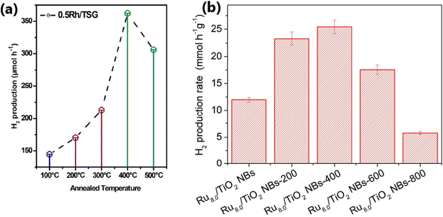 | ||
| Fig. 20 (a) Variation in the rate of hydrogen production on 50 mg of 0.5Rh/TSG(TiO2) as a function of calcination temperature (reproduced with permission from ref. 51. Copyright ©2018 Elsevier Ltd). (b) Variation in the rate of hydrogen production as a function of calcination temperature for the Ru (wt% = 8.0)/TiO2 NB photocatalyst (reproduced with permission from ref. 47. Copyright ©2016, Wiley-VCH). | ||
A comparison of the photocatalytic H2 evolution activity of Ru (wt% = 8.0)/TiO2NB (nanobelts) non-annealed sample and the same catalyst calcined at different temperatures (200 °C, 400 °C, 600 °C, and 800 °C), as illustrated in Fig. 20b, revealed that Ru 8.0/TiO2 NBs calcined at 400 °C showed the highest photocatalytic hydrogen production rate of 25.34 mmol h−1 g−1.47 The improved activity of Ru 8.0/TiO2 NBs@400 °C is due to its improved crystallinity with the formation of the crystalline-phase Ru/RuO2 and formation of an intimate junction between Ru/RuO2 and TiO2. With a further increase in the calcination temperature, an increased amount of RuO2 was formed due to the oxidation of Ru, which had a detrimental effect on the rate of hydrogen evolution.47
The majority of researchers tried to maintain a greater anatase phase content in TiO2. This is because although the rutile phase is stable, it has poorer photocatalytic activity compared to anatase because of its larger bandgap and smaller surface area. Thus, if this phase transition is not properly managed, the photocatalytic efficiency may significantly decline. Furthermore, high calcination temperatures can lead to particle growth and agglomeration, which reduces the surface area and active sites for photocatalytic reactions. Alternatively, inadequate calcination may result in the presence of leftover organic matter or partially degraded precursors, which can serve as recombination sites for charge carriers produced during the photocatalytic process and hinder the activity.
4.4. Effect of morphology
The morphology of TiO2 plays a considerable role in deciding the photocatalytic hydrogen evolution activity by affecting the interaction between the dopant and TiO2,186 migration of photogenerated electrons,179 and effectiveness of the heterojunction.179,186 TiO2-based photocatalysts with specific morphologies such as nanosheets,186 nanorods,186 and nanotetrahedrons167 have been studied for understanding the influence of morphology on photocatalytic H2 production. The TiO2 nanosheet with single-crystal structure and low density of defects was found to be highly effective in reducing the charge carrier recombination, thereby enhancing the rate of hydrogen evolution.186Wang et al. fabricated a 2D/1D heterojunction of TiO2/CdS composite with (001) facets of TiO2 and CdS nanorods, which showed a photocatalytic hydrogen evolution rate of 128.3 mmol g−1 h−1 with acetic acid-water mixture (20 mL acetic acid in 210 mL water) under visible light (300 W Xe arc lamp; λ > 400 nm), which is much higher than that by the conventionally prepared P25/CdS (35.3 mmol g−1 h−1).179 The outstanding photocatalytic performance of 2D/1D TiO2/CdS is attributed to the morphological features of TiO2 and the formation of an optimized 2D/1D heterojunction, leading to efficient charge separation and enhanced electron transport. The morphology of the cocatalyst also plays a vital role in enhancing the photocatalytic H2 production rate. Thus, between TiO2–Pd NSs (nanosheets) and TiO2–Pd NTs (nanotetrahedrons), the photocatalytic hydrogen production rate was higher on TiO2 integrated with ultrathin nanosheets of Pd due to the rapid generation of hot electrons and their transfer from Pd nanosheets.167 A comparison of the morphological features, optical properties and photocatalytic activities of TiO2–Pd nanosheets and TiO2–Pd nanotetrahedrons is shown in Fig. 21.
 | ||
| Fig. 21 (a) Schematic illustration, TEM (b and c), and HRTEM (d) images of TiO2–PdNSs. (e) Schematic diagram, TEM (f), and HRTEM (g) images of TiO2–Pd NSs with TiO2 nanosheets. (h) Schematic illustration, TEM (i) and (j), and HRTEM (k) images of TiO2–Pd NTs. (l) Schematic illustration and TEM (m) image of TiO2–Pd NTs with TiO2 nanosheets. UV-vis diffuse reflectance spectra (n), photocurrent response (o), PL spectra (p) and photocatalytic H2 production performance (q) of bare TiO2, TiO2–Pd NTs and TiO2–Pd NSs. Schematic illustrating the photocatalytic H2 evolution reaction on the samples of TiO2–Pd NSs and TiO2–Pd NTs (r) under UV and (s) vis-NIR light irradiation, respectively. Reproduced with permission from ref. 167. Copyright ©2016, the Royal Society of Chemistry. | ||
The photocatalytic H2 production activity of the Pt@CuO/TiO2 composite fabricated using TiO2 nanosheets was higher than that of Pt@CuO/TiO2 prepared using TiO2 nanorods.186 The relatively high activity of the nanosheet-based photocatalyst is due to a variety of reasons, as follows: (1) TiO2 nanosheets mainly have exposed relatively high surface energy (001) facets, whereas TiO2 nanorods are dominated by comparatively lower surface energy (101) facets, (2) CuO has stronger interactions with TiO2 nanosheets than with TiO2 nanorods, (3) CuO can form a more stable p–n heterojunction with TiO2 nanosheets, and (4) TiO2 nanosheets have a low density of defects, which reduce the possibility of charge recombination. Compared to conventional Pd/P25 TiO2, Pd/TiO2 nanosheets showed relatively higher activity for photocatalytic H2 production due to the greater number of exposed high surface energy (001) facets on nanosheets.170 In contrast, for the nanorod morphology, the aspect ratio is crucial for enhancing the photocatalytic water splitting, as reported by Fuet et al. for nanorods of rutile TiO2.192 The different works discussed above show that due to the larger surface area and more active sites, nanostructured TiO2 materials such as nanotubes, nanorods, and nanospheres generally show improved photocatalytic activity compared to bulk materials. Nevertheless, the production of these nanostructures frequently necessitates precise control of the synthesis parameters and more sophisticated and expensive techniques.
4.5. Crystallographic facet-dependent activity
Certain exposed facets of TiO2 can enhance the solar hydrogen generation to a large extent because of the effective electron–hole separation by way of enhancing the interfacial charge transfer, more exposed surface area, and high surface energy.136,170 The choice of TiO2 with unique tailored facets {001} or {101} in the composite has a significant influence on the photocatalytic hydrogen evolution performance.136,170,192,193 Liu et al. studied the influence of the (100), (001), and (101) crystal facets of TiO2 on the photocatalytic hydrogen generation activity of a TiO2–graphene composite and observed that the TiO2-100-graphene composite exhibited the highest rate of hydrogen evolution.152 The enhanced activity of the Ti-100-G composite was attributed to the formation of Ti–C bonds, which increased the rate of charge transfer, and thereby improved hydrogen production activity. In contrast, Ti–O–C bonds are formed in the Ti-001-G and Ti-101-G composites, leading to a reduced charge transfer rate and lower hydrogen evolution activity. Due to its very poor interfacial connections and unfavourable electronic structure, the Ti-001-G composite showed the lowest rate of hydrogen evolution.152 The preparation of TiO2–graphene nanocomposites, their physicochemical characteristics and a schematic illustration of the atomic structures of the interfaces between graphene and different TiO2 crystal facets and their photocatalytic process, and the photocatalytic H2 production activities are provided in Fig. 22. | ||
| Fig. 22 (a) Schematic illustration of the preparation of TiO2–graphene nanocomposites with controllable TiO2 crystal facets exposed. (b) Band structures of TiO2 and TiO2–graphene nanocomposites. (c) H2 evolution rates from methanol solution catalyzed by TiO2 and TiO2–graphene nanocomposites. (d)–(i) TEM and HRTEM images: (d) and (e) TiO2-101-G, (f) and (g) TiO2-001-G, and (h) and (i) TiO2-100-G. Schematic illustration of atomic structures of interfaces between graphene and different TiO2 crystal facets and the photocatalytic process by TiO2–graphene nanocomposites: (j) TiO2-100-G, (k) TiO2-101-G, and (l) TiO2-001-G. Reproduced with permission from ref. 152. Copyright ©2014, Wiley-VCH. | ||
Exposed facets of certain dopants can also influence the rate of hydrogen generation due to the formation of appropriate energy levels and reduced rate of electron–hole recombination by trapping the photogenerated electrons. For example, The Pt/TiO2 photocatalyst having (111) facets of Pt with a higher Fermi level is highly effective for trapping the electron in the conduction band of TiO2 than that with the (100) facets of Pt.188 In another study, Qi et al. reported that a CdS-sensitized Pt/TiO2 nanosheet photocatalyst with (001) exposed facets showed outstanding water splitting activity due to the special electronic and surface properties of the (001) facets.194 Compared to {101}-TiO2/CdSe QDs, the relatively high photocatalytic production rate shown by {001}-TiO2/CdSe QDs is due to the enhanced charge separation and efficient electron transfer from CdSe QDs to the (001) facets of TiO2.136 Due to the differences in their surface energy, reactive site density, and charge carrier dynamics, different facets of TiO2 exhibit different photocatalytic activities. Hence, facet-controlled synthesis methods are required to maximise the photocatalytic performance. For example, nanocube and octahedron morphologies only expose (100) or (111) facets, respectively, while truncated octahedron exposes both (100) and (111) facets. Thus, by fine tuning these methods, it is possible to improve the performance of photocatalysts and well-defined synthetic methodologies are required.
4.6. Particle size
Particle size can significantly affect the performance of photocatalysts by affecting the number of active sites, charge transfer and electron–hole recombination rates, and light penetration.136,137 Photocatalysts with a smaller particle size possess a large number of active sites and accelerated electron transfer process.117 Contrarily, large-sized catalyst particles not only reduce the number of active interfaces but also block the penetration of incident light.118 Also, the particle size of metal dopants influences the energy separation between the Fermi level of the metal and the conduction band of TiO2, which directly affect the carrier separation ability of the photocatalyst.195 In the case of SPR metals such as Ag and Au, their absorption wavelength varies with their particle size and morphology.39,196 Dopants with small-sized particles facilitate a high dispersion of particles on crystalline TiO2. However, metallic particles with a very small size show poor stability due to the high surface energy and easy detachment of particles from the TiO2 surface when stirred intensely.197 This suggests that material integration is of great significance for any sustainable operation for long reaction time.198 Yang et al. reported that for a given gold loading, Au@TNT with a reduced particle size showed an improved photocatalytic performance and attributed to the high dispersion of Au particles on the surface of TiO2 and its modified electronic properties.168 Metal nanoparticles with a small particle size produce an increased amount of highly energetic surface sites, which make the catalyst highly effective for photo-injection and enhance the electron transfer process. The modified electronic state has a positive effect by improving the charge transfer and electron–hole separation efficiency.168 The superior photocatalytic H2 production activity due to highly dispersed Cu0 nanoparticles in Cu–TiO2 MS (mesoporous microporous) photocatalyst,197 small-sized Au nanoparticles in Au-loaded mesoporous S,N-TiO2 (SNT),199 and Pd and Pt nanoparticles in TiO2195 substantiate the importance of controlling the metal particle size to achieve the desired properties and enhancing the photocatalytic efficiency.Metal nanoparticles such as Au and Pt with a size in the range of 1–10 nm supported on TiO2 lead to an increase of energy gap between the Fermi level of metal nanoparticles and the conduction band of TiO2, resulting in improved charge separation and enhanced hydrogen production activity.195 Gold nanoparticles were synthesized via a seed-mediated growth method for the sensitization of Pt/TiO2 catalysts (Fig. 23a) and it was evident from the TEM images (Fig. 23b–e) that narrow-sized Au particles were obtained through this method. Among the Au-sensitized Pt/TiO2 photocatalysts with different particle sizes of Au (10, 20, 30, and 50 nm) for photocatalytic hydrogen production, the Au nanoparticles with a particle size of 20 nm showed the highest performance under visible light (Fig. 23g and h).200 The size of Au nanoparticles is clearly evident from the TEM images, as illustrated in Fig. 23, and the results show that the SPR effect and the electron injection into the CB of TiO2 depends on the particle size of Au (Fig. 23f and h).200 Generally, smaller particles possess a large surface area and a greater number of reaction sites per unit weight of catalyst. Nonetheless, smaller particles can sometimes lead to a decline in photocatalytic activity with time due to particle aggregation. If the size of the particles is smaller than twice the width of the space charge layer, the extent of band bending decreases, which eventually diminishes the potential to separate e−/h+ pairs. Alternatively, visible light-absorbing small quantum dots could be grown inside the pores of a wide bandgap semiconductor and this approach is likely to result in higher activity due to the inherent and inevitable formation of heterojunctions.
 | ||
| Fig. 23 (a) Schematic diagram of the synthesis of Au nanoparticles supported on Pt/TiO2 composite catalysts. TEM images of the synthesized gold nanoparticles with a size of approximately 50 nm (b), 30 nm (c), 20 nm (d), and 10 nm (e). TEM images of Pt/TiO2. (f) Plausible photocatalytic mechanism of Au-sensitized Pt/TiO2 under visible light. (g) Photocurrent response of Au nanoparticles with different sizes supported on Pt/TiO2 nanocomposites under visible-light irradiation (λ > 420 nm). (h) Hydrogen-production activity of different catalysts under visible-light irradiation (λ > 420 nm) in water/methanol mixture. Reproduced with permission from ref. 200. Copyright ©2017, the American Chemical Society. | ||
4.7. Porosity
The porosity of a photocatalyst has a significant influence on its photocatalytic hydrogen production rate given that it increases the surface area, providing a large number of exposed surface sites, enhances the absorption of a large number of reactant species, enhancing the light absorption performance, and increases the mass transfer rate.15,88,201 A macroporous channel in a photocatalyst can increase the mass transfer within the macro-mesoporous framework and enhance the light absorption performance.15 The presence of a meso-macroporous network in a TiO2 photocatalyst improved its light-harvesting ability by transferring the incident photon flux into the internal surface of mesoporous TiO2 through multiple internal reflections.155 This type of macro-mesoporous architecture additionally supports the easy channelization of photogenerated electrons via the mesoporous walls and facilitates the electron transportation to the surface of TiO2via the microporous channel. Consequently, the electron–hole recombination is suppressed and the photocatalytic activity is enhanced.182 The 3D ordered macroporous Pt/TiO2–ZrO2 composite synthesized using a combination of vacuum impregnation and photoreduction method, for example, exhibited high photocatalytic water splitting activity to H2 due to the enhanced light absorption effected through multiple internal reflections in its pores.155A comparison of the H2 evolution activity between Pt-deposited mesoporous TiO2 nonporous Pt/TiO2-P25 revealed that mesoporous Pt/TiO2-450 showed better activity than non-porous Pt/TiO2-P25 because the mesoporous network facilitates efficient charge transfer by forming suitable interfaces and the reactants can easily diffuse through the pores.202 Li et al. reported that the CuO/TiO2 photocatalyst prepared by the chemical adsorption decomposition method (CAD) consisted of a large number of small pores, which facilitated the absorption of a large number of reacting molecules on its surface due to the presence of more active sites and promoted the hydrogen generation activity.184 One of the reasons for the enhanced H2 production rate displayed by the Au-deposited mesoporous S,N-TiO2 (SNT) photocatalyst with a pore diameter in the range of 8 to 13 nm is due to its mesoporous nature, which enhanced the light-harvesting ability of the material.199 Further, using green leaves and highly porous architecture was proved to be beneficial for photocatalysis and light harvesting applications.203,204 For example, Devaraji et al. demonstrated the use of a green leaf as a template to produce an inorganic leaf to produce ZnO with a nano-micro architecture and demonstrated its use for the efficient oxidation of benzene to phenol under UV light. In another work, Chen and coworkers demonstrated the importance of the porous architecture for enhanced photocatalytic H2 production by fabricating TiO2 nanotube arrays (TNTAs) grown on titanium fiber of a titanium web (TNTA-web) and titanium foil (TNTA-foil).205 The TNTA-web generated 40 mmol h−1 m−2 of hydrogen, while the TNTA-foil failed to produce hydrogen under similar conditions. Further, the addition of the same amount of Pd nanoparticles to the TNTA-web and TNTA-foil resulted in an increase in the production rate to 130 and 10 mmol h−1 m2, respectively. The enhanced photocatalytic H2 production activity of the TNTA-web material was attributed to its unique dual porosity. The synthesis procedure and morphological analysis of TNTA-web are depicted in Fig. 24. Photocatalysts having dual porosity, such as hierarchical porous-structured materials containing a combination of macroporosity and mesoporosity, are believed to be more advantageous than single porosity. However, more research in this direction is needed for proper control of the porosity, which can be achieved by careful variation of the synthesis parameters and/or adopting novel synthesis strategies. Establishing a structure–activity relation is an interesting aspect in photocatalytic research, which deserves more attention.
 | ||
| Fig. 24 (a) Synthesis of Pd/TNTA-web (3D TiO2 nanotube array). Scanning electron microscopy (SEM) images of the pristine titanium-web substrate (b) and (c) and TiO2 nanotubes arrays on the web (d), (e) and (f). HR-TEM image of a nanotube (g), SEM image (h), TEM image (i) and HRTEM image (j) of the TNTA-web with 0.1 mg cm−2 Pd (0.26 wt%). Reproduced with permission from ref. 205. Copyright ©2018, the Royal Society of Chemistry. | ||
4.8. Amount of catalyst
The rate of photocatalytic hydrogen evolution also relies on the quantity of catalyst to a large extent. In general, the catalyst shows the maximum photocatalytic performance at an optimal amount, and with an increase in the amount of catalyst, the photocatalytic H2 evolution, generally decreases and/or levels off, which can be explained by the following reasons:182 (1) at higher concentrations of photocatalyst, there is a reduction in the light penetration depth in the suspension of catalyst; further, light scattering occurs more in a suspension compared to light absorption. (2) An excess amount of catalyst may increase the electron–hole recombination rate. (3) The aggregation of catalyst particles is generally high in slurry form with an uneven distribution of particles, resulting in a vast differences in contact and reaction rate, and hence the diffusion of reactants and photogenerated charges towards the reaction sites is less effective in the suspension form. (4) The active site of the catalyst can be covered up by the presence of a large quantity of catalyst.43The photocatalytic performance of Ag/TiO2 in water splitting reaction for different catalyst amounts revealed that the H2 production rate increased initially with an increase in the catalyst concentration from 15 to 20 mg L−1, and with a further increase in catalyst concentration, the activity declined (see Fig. 25a).112 The catalyst in excess amount may hinder the absorption of radiation, and in certain cases it accelerates the electron–hole recombination.112 The amount of catalyst needed for achieving the optimum activity may vary as the nature of the catalyst, catalyst composition and reaction conditions vary. For example, as illustrated in Fig. 25b, the H2 production rate on Ni/γ-Al2O3/CNT-TiO2 was the maximum with 10 mg catalyst and the activity decreased with a further increase in catalyst amount.102 The excess amount of catalyst adversely affected the light penetration, which decreased the overall catalytic performance.102 In fact, an earlier review66 listed the very high activity associated with a small amount of catalyst (1–3 mg in ∼50–100 mL solution), whereas a larger quantity of the same catalysts (10–200 mg in ∼50–200 mL solution) showed a large drop in hydrogen production activity. The large difference in activity is attributed to the significant light scattering with a larger amount of catalyst quantity, whereas efficient light absorption with a small quantity of catalyst in large volumes of solution. Based on the available literature and above discussion, it can be concluded that careful optimisation of the amount of photocatalyst is necessary to extract the best catalytic performance from a photocatalytic material. Nonetheless, how it can be scaled-up for large volume applications also needs to be addressed. Although this is an engineering issue, this thinking is likely to bring clarity and minimize the problems in the future.
 | ||
| Fig. 25 (a) Photocatalytic hydrogen evolution activity of Ag/TiO2 by varying the amount of catalyst. Reproduced with permission from ref. 112. Copyright ©2019, Elsevier Ltd. (b) Variation in photocatalytic H2 evolution rate with respect to the amount of Ni/γ-Al2O3/CNT-TiO2 catalyst. Reproduced with permission from ref. 102. Copyright ©2017, Elsevier Ltd. | ||
4.9. Amount of dopant
The photocatalytic activity of TiO2 can be drastically improved by using various dopants. However, the amount of dopant is a critical factor in photocatalysis. It has been observed that TiO2-based composites for a given dopant show the maximum performance at an optimum concentration in the TiO2 matrix, and with a further increase in the dopant concentration, the photocatalytic activity decreases.85 A high concentration of dopant in TiO2 acts as the recombination center for electrons and holes85 and block the surface active sites. This reduces the light utilization ability of the catalyst and reaction rate, and thereby the photocatalytic hydrogen production rate decreases.134 An increase in the loading of dopants may also cause the agglomeration of particles and particle growth rather than their uniform distribution.104 However, an optimum amount of dopant can effectively separate the electrons and holes and enhance the charge transfer through the interface between TiO2 and the dopant and its efficient utilization during the photocatalytic reaction. There are several reports available in the literature illustrating the effect of dopant concentration on the photocatalytic H2 production activity.As illustrated in Fig. 26a, the photocatalytic H2 evolution activity of Cu-decorated TiO2 containing different wt% of Cu (1, 2, 3, 4, and 5 wt%) revealed that the amount of hydrogen produced increases up to 3 wt% of Cu (3.33 mmol g−1 h−1), and with a further increase in Cu concentration, the activity is reduced.104 This study revealed that 3 wt% Cu is the optimum concentration to achieve the maximum activity, and at a higher concentration of Cu (above 3 wt%), the aggregation of Cu particles occurs on the surface of TiO2 and these agglomerated Cu nanoparticles act as recombination centers for photogenerated electrons and holes. This shows that a suitable mass ratio of components is crucial to generate an efficient interface for excellent photocatalytic hydrogen evolution.
 | ||
| Fig. 26 (a) Variation in the H2 evolution activity of TiO2 decorated with different wt% of Cu. Reproduced with permission from ref. 104. Copyright ©2017, the Royal Society of Chemistry. (b) Rate of hydrogen evolution of TiO2 and TiNi samples with different loadings of Ni. Reproduced with permission from ref. 16. Copyright© 2018, the Royal Society of Chemistry. | ||
In another variation, the photocatalytic hydrogen production activity of Cu2O–TiO2/rGO revealed that TiO2 with the optimum Cu loading of 1 wt% and GO loading of 3 wt% showed the maximum performance because of the enhanced charge transfer and excellent light absorption capacity of the material. The highest photocatalytic H2 production activity was observed with 3 wt% Au-loaded mesoporous S,N-TiO2 when Au-deposited mesoporous S,N-TiO2 with different wt% of Au (0.5, 1, 2, 3, 4 and 5) were compared for the reaction.199 In this case, a high content of gold blocked the active sites and obstructed the penetration of light into the catalyst surface. The high concentration of metal on the surface of TiO2 may also act as electron–hole recombination centres, which reduces the rate of photocatalytic hydrogen production.85 When a combination of metal nanoparticles is employed for the fabrication of TiO2-based composites, the uniform distribution of all the metal nanoparticles on TiO2 is crucial to achieve the maximum photocatalytic performance.85
Reddy et al. reported that a bimetallic Cu/Ag@TNT-2 (CAT-2) photocatalyst with the optimum amount of Ag and Cu prepared using a mixture of 0.1 M Cu and 0.1 M Ag precursor showed the highest rate of photocatalytic hydrogen generation due to the uniform dispersion of Ag and Cu on TiO2.99 A lower number of active sites was present at a low concentration of Cu and Ag on the surface of TiO2, whereas a high concentration of metal nanoparticles led to poor electron transfer.99 Wei et al. reported that a TiO2–Ni hybrid photocatalyst with the optimum Ni amount of 1 mol% showed the highest rate of hydrogen evolution during the photocatalytic water splitting reaction.16 An excess Ni loading limited the light absorption ability and blocked the active sites of the catalyst, leading to a decrease in activity (see Fig. 26b).
The photocatalytic hydrogen evolution activity of Pd-integrated TiO2 nanosheets revealed that the photocatalyst showed the highest activity with an optimum Pd loading of 0.1 mg cm−2.205 The H2 evolution activity decreased when the amount of Pd was higher than the optimum loading due to the increase in Pd particle size and incorporation of Pd atoms in the bulk part rather than on the surface of TiO2. Moreover, the integration of a large amount of Pd in TiO2 limits the expansion of the Pd–TiO2 interface and reduces the number of charge carriers. The incorporation of a small amount of non-metal dopants such as N in anatase TiO2 nanotubes creates defect centers, while maintaining the anatase phase, and strongly promotes the photocatalytic H2 evolution performance of TiO2 nanotube layers, whereas the high-dose N incorporation leads to amorphization of the incorporated region of TiO2.114 In conclusion, the effectiveness of TiO2-based photocatalytic materials is highly sensitive to the amount of dopant used. Both insufficient and excessive dopant levels can significantly impair the photocatalytic efficiency by either failing to adequately enhance charge separation or by introducing recombination centres, respectively.
4.10. Thin film approach
Photocatalysts in thin-film form show a significantly higher performance than that in particulate form for hydrogen evolution.165,206,207 The catalyst nanoparticles assembled in thin film are nearly uniformly spread across the substrate and have a large exposed surface area to the reactants and irradiation, resulting in more efficient interactions among the catalyst particles, light and reactants with relatively less mass transfer constraints. The possible reasons for the enhanced solar hydrogen evolution activity of photocatalysts fabricated in thin film form are as follows:206 (1) by optimizing the film thickness to around 10 μm, the light absorption achieved is the maximum in thin films, while the same material in suspension form scatters light, rather than absorbing it; (2) the exposure of the maximum surface to solar radiation in thin film form is beneficial for enhancing the light-harvesting and light-induced electron excitation processes and increases the hydrogen production and apparent quantum yield (AQY); (3) the maximum utilization of surface area and active sites is possible in thin film form, which is good for the diffusion of charges toward the reaction sites; (4) better contact of catalyst nanoparticles is possible in the film form, which enhances the charge separation and charge utilization, whereas charge recombination is severe in powder form; and (5) thin film form with some surface roughness is beneficial for the internal scattering of light within the depth of thin films and enhances the charge carrier production/utilization. In powder form, additional energy in the form of electricity is needed for constant stirring to make the catalyst particles highly homogeneous in the reaction medium.43,66,165,208 Unlike the case with solar cells, the charge carriers generated during the photocatalytic process are efficiently consumed within an ensemble of particles in a small area in thin film and hydrogen formation occurs from every part of the thin film. This indicates that the charge carriers do not need to diffuse long distances in the order of microns.165,209A comparison of the solar H2 production activity of titania (P25) and Pd/P25 fabricated in thin film form (4.69 cm2) on a glass plate and their powder form counterparts revealed that the Pd/P25 catalyst (1 mg) fabricated in thin film form resulted in an H2 production rate of 104 mmol h−1 g−1, which was about 11–12-times higher than the Pd/P25 catalyst (25 mg) in powder form.165 The digital photograph, FESEM images and photocatalytic performance of the prepared thin film are depicted in Fig. 27a–d. The enhanced activity of Pd/P25 in thin film form is due to its maximum exposed surface area to the reactants and sunlight and other advantageous aspects of thin film, as described above. A similar trend in the photocatalytic H2 production activity of a catalyst in thin film form compared to its powder counterpart was also observed with Ag/TiO2 nanocomposites (Fig. 27e).43
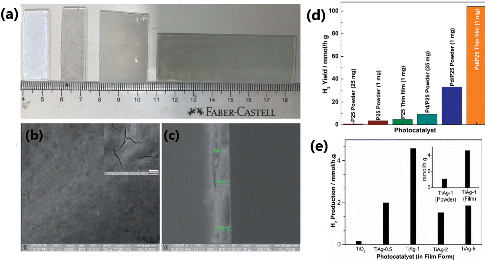 | ||
| Fig. 27 (a) Digital photographs of thin films of P25 and Pd/P25. FESEM images of Pd/P25 thin films over a glass plate at a scale bar of 2 μm (b) and (c) cross-sectional view of a freshly cleaved thin film (scale bar: 10 μm). Inset in (c) shows the cracks. (d) Photocatalytic H2 evolution activity in the particulate and thin film form of different catalysts (reproduced with permission from ref. 165. Copyright©2019, the Royal Society of Chemistry). (e) Photocatalytic H2 production activity of mesoporous TiO2 and Ag/TiO2 nanocomposites, measured in thin-film form, in aqueous methanol solution under direct sunlight. Reproduced with permission from ref. 43. Copyright ©2021, Wiley-VCH. | ||
The excellent catalytic performance of Pd/TiO2,165 Ag/TiO2,43 Cu–Ni/TiO2,3 CuxO/TiO2,209 Cu–Ag/TiO2206 and AuPd/C/TiO266 fabricated in thin-film form compared to their powder counterparts has been demonstrated in the literature. Tudu et al. reported that the thin film form of the Cu–Ni/TiO2 (1:1 = Cu:Ni) photocatalyst exhibited an enhanced rate of hydrogen evolution (41.7 mmol h−1 g−1) compared to its powder form (1.75 mmol h−1 g−1) due to the efficient charge generation and its utilization in the film form, which mimicked the natural photosynthesis by green leaves.3 In another report, the film form of the AuPd/rGO/TiO2 photocatalyst displayed an enhanced hydrogen generation (21.5 mmol h−1 g−1) performance compared to its powder form by a factor of 43 times. The higher activity of the film form of the catalyst is attributed to its high light absorption capacity, efficient contact between the particles, and remarkable charge generation and utilization.66
An important aspect of assembling and integrating thin films is to enhance the number of heterojunctions or Schottky junctions. A recent work on integrating BiVO4 in the micro and mesopores of P25-TiO2 showed a solar to fuel efficiency of 31% under one sun condition for artificial photosynthesis to produce methanol and formaldehyde. One of the main reasons attributed is the observation of 174 trillions of BiVO4–TiO2 heterojunctions in 1 mg of material, as reported by Salgaonkar et al.210 To the best of our knowledge, this was the first time that the number of heterojunctions in a material was reported, which was calculated based on the pore-size distribution and surface area by measuring them carefully before and after integrating BiVO4 with TiO2. This indeed opens a new window to fabricate highly integrated materials for efficient charge separation and their diffusion to the redox sites. Similar works may lead to an enhancement in light to chemical conversion for a variety of reactions.
5. Co-production of H2 and value-added products (VAPs) from biomass components for the concurrent utilisation of electrons and holes
Despite the efficiency of utilizing sacrificial reagents as electron donors or hole scavengers to boost photocatalytic hydrogen production, their oxidized products are mostly ignored or unexplored. Recent studies indicated that some catalysts can produce oxidized products of sacrificial reagents together with H2 due to the concurrent utilization of photogenerated electrons and holes.211 Most of the studies usually use comparatively costlier sacrificial reagents such as methanol; however, if methanol can be converted to value-added products (VAPs) such as formic acid, the operating expenses of photocatalysis can be reduced. Moreover, the utilization of the biodiesel byproduct glycerol as a sacrificial reagent can lead to the coproduction of H2 fuel together with VAPs. Compared to pure water-splitting systems, these coupled photocatalytic H2 production systems will be more reactive and economical for H2 generation. However, some challenges, such as the removal of liquid products from the reaction system, low conversion efficiency, and product selectivity, need to be addressed. In this case, appropriate chemical process design, coupled with efficient separation techniques, can solve the former issue. Currently, the coproduction of H2 and the generation of VAPs from sacrificial reagents are still in their infancy, and thus some advanced research in this field is required to tackle the obstacles and explore photocatalytic H2 production coupled with the oxidation of sacrificial reagents with a wide range of sacrificial reagents, especially biomass-derived ones.52A bifunctional p–n heterojunction of NiO–TiO2 photocatalysts could simultaneously produce H2 and VAPs such as glyceraldehyde and dihydroxyacetone from a glycerol–water solution (10% v/v) under UV-visible light irradiation.211 The best-performing catalyst (7.5% Ni-loaded TiO2) produced 8000 μmol h−1 g−1 hydrogen and could achieve 20% conversion of glycerol. Interestingly, at the beginning of the reaction, the yield of glyceraldehyde was higher than that of DHA; however, after 24 h of reaction, almost the same yields of both the products were obtained.
The reduction reaction occurs on the surface of TiO2, while the glycerol oxidation occurs on NiO. The feasibility test revealed that glyceraldehyde contributes the highest share of annual earnings (89%), followed by dihydroxyacetone (11%) and H2 (0.03%). The photocatalytic H2 production performance, glycerol oxidation and corresponding reaction mechanism of NiO–TiO2 photocatalysts are provided in Fig. 28. In another work, Bajpai et al. achieved an improved H2 production rate of 18 mmol h−1 g−1 with the generation of three VAPs, glycolaldehyde, DHA, and formic acid, from a glycerol–water solution with Au integrated with P25-TiO2 (Au@TiO2).52 The Au@TiO2 catalyst system achieved 4–10% conversion of 0.05 M glycerol to VAPs. The photocatalytic experiments were carried out under three different reaction conditions (aerobic, anaerobic and dry air) and under 2 different light sources (direct sunlight and one sun condition with 100 mW cm−2). The overall products yield was higher under aerobic conditions and sunlight irradiation compared to anaerobic and dry air conditions. However, 7.5 mmol g−1 CO2 was also observed under aerobic conditions due to the over-oxidation of glycerol. The liquid and gaseous products were the same when the photocatalytic experiments were performed under one-sun conditions. However, the CO2 production declined (5.3 mmol g−1) under one sun condition compared to direct sunlight. The dual-function of the catalyst was ascribed to the improved charge transport and efficient separation of photogenerated charge carriers due to the highly dispersed and electronically integrated Au with TiO2. The development of photocatalytic systems that can selectively produce the desired products in high yields from biomass components, without compromising the yield of H2 is a significant challenge in this area. It should also be noted that a similar concept in the electrolysis of aqueous glycerol has been growing rapidly in the last 3–4 years and a few recent works is worth mentioning. Chauhan et al.212 achieved a low-voltage pathway to water electrolysis, while producing H2 at the cathode and value-added products at the anode.
 | ||
| Fig. 28 (a) Schematic illustration of the photocatalytic process. Comparison of H2 production performance of samples with different nickel loadings (b). (c) Glycerol conversion over different photocatalysts. Yield of liquid products obtained with best-performing catalyst (d) and (e) plausible reaction mechanism. Reproduced with permission from ref. 211. Copyright 2023, Elsevier. | ||
6. Simultaneous oxidation of organic contaminants and hydrogen evolution from wastewater
Industrial and domestic areas produce a huge amount of wastewater daily, which is a serious environmental issue. Furthermore, the treatment of wastewater is an energy consuming process, whereas wastewater itself is a rich source of energy and it contains four to five times more energy than needed for its treatment. For example, wastewater is a potential source of biohydrogen, a clean energy and a feedstock chemical.213 The majority of studies on hydrogen generation used pure water as the hydrogen source. Typically, holes oxidise water to make oxygen and photo-generated electrons convert water into hydrogen. However, given that the water oxidation process is a slow process, molecules such as alcohols, organic acids, and triethanolamine are frequently utilised as sacrificial agents to consume the photo-generated holes to increase the hydrogen production efficiency, thus making the overall process uneconomical.213 Recently, many studies have demonstrated that the construction of TiO2-based photocatalytic systems is thermodynamically advantageous for both the generation of hydrogen and the oxidation of organic contaminants from wastewater.213–220 Energy production and environmental cleanup are two advantages of using wastewater as a feedstock for photocatalytic hydrogen production. Wastewater contains a variety of organic contaminants that can act as sacrificial agents, consuming photogenerated holes and lowering the recombination rates to increase the efficiency of hydrogen generation. TiO2 may oxidise common pollutants including dyes, pharmaceuticals, and industrial effluents, facilitating the breakdown process and the generation of hydrogen.213–216Wu et al. developed a dual-functional photocatalyst system for the treatment of pharmaceutical-contaminated water using Co3O4-modified {001}/{101}-TiO2(TC) nanosheets. The unique aspect of this photocatalytic system is that the p-type semiconductor Co3O4 creates a p–n junction with TiO2 and the {001}/{101} facets of TiO2 form an inherent surface heterojunction, which enhances the charge carrier separation. The electrons on the surface of the TiO2 nanosheet can convert water molecules into molecular hydrogen, while the holes on the Co3O4 surface effectively oxidise pharmaceutical contaminants in the wastewater.213 The interesting idea of the concurrent utilization of electrons and holes was employed by Salgaonkar for different isomers of butanol oxidation to the corresponding butanal/butanone and hydrogen with TiO2–Pd and Pd coated with half-a-monolayer of Pt under visible light.216 This generic procedure for the selective oxidation of alcohol to aldehyde/ketone with H2 is worth pursuing for many different substrates. The mineralization of a serious endocrine disruptor, namely endosulphan, was investigated by Devaraji et al. with a solid solution of ZnO–ZnS under direct sunlight.214 The a-TiO2 (anatase TiO2)/b-AC (biomass activated carbon) nanocomposite synthesized through the ultrasonication technique was very effective for sulphide wastewater treatment together with excellent photocatalytic hydrogen production (400 mL h−1).217 Non-metal-doped TiO2 (NMx-TiO2, where x is the weight percentage of non-metal element) nanocomposites displayed a high hydrogen production rate and COD elimination simultaneously when employed for waste water treatment.215 In this case, using a catalyst loading of 4 g L−1 and light intensity of 5.93 mW cm−2, 7 wt% P-loaded TiO2 (P7/TiO2) could achieve a hydrogen production rate of 8.34 mmol g−1 and 50.6% COD elimination.
The simultaneous oxidation of organic waste and water reduction offer a viable solution to major environmental and energy problems. The goal of ongoing research and development is to remove financial and technological obstacles, enabling the utilization of these technologies in everyday life and their public availability. The development of more sophisticated photocatalysts with increased efficiency has been the focus of recent research. Many organic wastes, such as plastic wastes, agricultural, and industrial pollutants, can be efficiently broken down by photocatalytic reactions. This helps in decreasing the environmental problems caused by waste accumulation. Also, the photocatalytic breakdown of harmful organic compounds into less toxic chemicals may reduce the water and soil pollution.
7. Photoreactor setup
The amount of H2 produced during a photocatalytic process not only depends on the efficiency of the catalyst system, but also on the photoreactor setup. The photoreactor setup plays an important role in the solar to hydrogen (STH) or solar to chemical (STC) conversion efficiency. An ideal photoreactor should facilitate the maximum absorption of incident photons on the catalyst surface with minimal loss. The photoreactor should be designed in such a way that most of the incident irradiation must fall on the surface of the photocatalyst. The classification of photoreactors is based on their mode of operation, number of phases involved, and the type of membrane used.221 The commonly used photoreactors include slurry type, fixed bed and membrane photoreactors. Annular reactors are the most popular slurry-type photoreactor.222 Based on the relative positions of the reactor and the light source, annular photoreactors are further classified into externally illuminated photoreactors and internally illuminated photoreactors. Among the fixed-bed photoreactors, monolith, optical fiber, honeycomb, cylindrical and thin film photoreactors are commonly used. The annular reactor is a tubular reactor with a light source located only at its axis.222 There are some technical and economic challenges in large-scale hydrogen production using photocatalytic reactors, which can only be profitable in terms of energy if the energy output is greater than the energy input. Hassan et al. fabricated an inner-irradiation quartz annular reactor illuminated with a 300 W Xe lamp with vacuum and recirculation pumps, a gas collector and a water-cooled condenser.223 This photoreactor setup for photocatalytic water splitting reaction in the presence of 0.1 g of TiO2–CuO composite nanofiber photocatalyst suspended in 1 M KOH solution resulted an H2 production rate of 2116 and 2715 μmol g−1 in an oxygen and air atmosphere, respectively. In a different study, a photoreactor comprised of a flat cylindrical Plexiglas cell, equipped with an optical window made of Pyrex glass and connected to a closed stainless steel system and filled with a photocatalyst bed prepared from 14 mg of Pt/Cu/TiO2 photocatalyst with different Cu/TiO2 ratios in the range of 0.05 to 0.5 wt% and 0.5 wt% Pt on quartz beads was used for photocatalytic water splitting reaction using a 20% v/v methanol-water mixture as the hydrogen source and a xenon arc lamp having a 40.0 mW cm−2 power density as the light source.224 Under these conditions, the Pt/Cu/TiO2 photocatalyst containing 0.1 wt% of Cu produced the highest hydrogen production rate of 27.2 mmol h−1 g−1.224 In another variation, by employing a Photo-CREC Water-II (PCW-II) reactor and 0.25 wt% Pd–TiO2 photocatalyst, Rusinque and coworkers generated an H2 volume of 113 and 29 cm3 STP under UV and visible light irradiation, respectively, for 6 h.225 They used 6 L of water and 0.15 g L−1 of photocatalyst during the reaction. PCW-II is a slurry-type batch reactor equipped with a storage tank to house the photocatalyst, water and organic scavenger (ethanol). This tank also possesses two ports for gas and liquid phase sampling. The PCW-II reactor has several advantages such as uniform distribution of catalyst with well-mixed suspension, a high surface to volume reactor ratio, negligible catalyst fouling, comparatively higher UV with no internal/external diffusion transport and visible light transmittance (97%), and higher resistance towards chemicals. Generally, most researchers use batch reactors; however, their low mass transfer and limited light penetration constrain the light absorption and H2 production efficiency of photocatalysts.226 The above-mentioned drawbacks of batch reactors can be solved if a flow membrane reactor is employed. In this context, a flow membrane reactor was employed for photocatalytic methanol dehydrogenation and reforming. The flow membrane reactor consisted of three major parts including a reactant vessel, reactor and product collector. A detailed schematic diagram and digital photograph of the flow membrane reactor are shown in Fig. 29a and b, respectively. By employing this membrane reactor and a 300 W xenon lamp (T: 303 K, P: 1 atm), the optimized catalyst (1% Cu/PC50) fabricated in thin film form on a glass fibre membrane exhibited a hydrogen production rate of 25487 and 33702 μmol g−1 h−1 at 303 and 333 K, respectively.226 The photocatalytic performance and mechanism of the Cu/PC50 photocatalysts are shown in Fig. 29c–e. The H2 production rate observed with the flow membrane reactor was 1.63-times higher than that obtained with the conventional batch reactor. The enhanced H2 production efficiency of 1% Cu/PC50 in the flow membrane reactor can be attributed to the improved mass transfer, which subsequently enhanced the adsorption and desorption of the reactants and products during photocatalysis. The implementation of membrane reactors compared to other conventional-type reactors for photocatalytic hydrogen production is not only a cost-effective approach but also enhances the separation, sustainability, yield, and selectivity for H2.
 | ||
| Fig. 29 (a) Digital photograph and (b) schematic diagram of the flow membrane reactor used for photocatalytic methanol dehydrogenation and reforming. (c) H2 yield obtained with different Cu wt% on PC50. (d) Amount of H2 produced with 1% Cu/PC50 at different temperatures. (e) Schematic illustration of photocatalytic process on 1% Cu/PC50 in a flow membrane reactor. Reproduced with permission from ref. 226. Copyright©2022, the Royal Society of Chemistry. | ||
Conclusion and perspectives
Solar hydrogen production with water as the main hydrogen source employing TiO2-based semiconductor photocatalysts is a renewable process and an alternative to the steadily increasing demand for energy and the environmental issues pertaining to the increasing consumption of fossil fuels. In this regard, the present review aimed to summarize the research carried out in the last decade in the area of photocatalytic hydrogen evolution. In this review, we highlighted the recent progress in the material integration aspects by describing the integration of TiO2 with different categories of materials and how this helps in tailoring the electronic and optical properties for activity tuning in solar H2 production with water as the main source. The structure–activity correlation of TiO2-based photocatalysts was emphasized to understand the mechanistic aspects and how the entire photocatalytic hydrogen production area has been progressing. We also discussed the importance of fabricating photocatalysts in thin-film form for enhanced photocatalytic activity and scalability using existing photocatalysts.The integration of TiO2-based photocatalysts with a second light-absorbing component and/or co-catalyst can significantly influence their H2 production rate. Metal nanoparticles in the form of single atoms and clusters reduce the metal loading and improve the catalytic efficiency. The porosity of a photocatalyst influences the solar hydrogen production rate by providing a large number of surface exposed sites and enhances its light-harvesting ability by transferring the incident photon flux into the internal surface of mesoporous TiO2 through multiple internal reflections and increasing the mass transfer rate. The photocatalysts fabricated in thin-film form show a significantly high performance for solar hydrogen production compared to the same catalysts in particulate form because the catalyst nanoparticles fabricated in thin film are highly connected across the substrate and have a larger exposed surface area to the reactants and sunlight with relatively less mass transfer constraints. The efficient and concurrent utilization of both photogenerated holes and electrons is very important to improve the photocatalytic efficiency of materials and the overall energy efficiency of the process. We also discussed the importance of performing the TiO2-based photocatalytic water splitting reaction in different reactor setups for enhancing the photocatalytic performance of the material and its scalability.
Continuous and dedicated efforts are needed in the area of photocatalytic hydrogen generation to fabricate commercially viable catalysts in scalable form that are efficient to produce sufficient quanta of charge carriers and their utilization. Thus far, less emphasis has been placed on the scalability and long-term stability of the photocatalytic material. In fact, for real world applications, photocatalysts that can deliver the same performance for several months (or even a year) and their scalability are necessary, and hence focus should be placed on developing novel photocatalysts with exceptional stability together with scalability towards commercial applications. Despite the significant advancements in this field, the solar-to-hydrogen (STH) conversion efficiency still needs to be improved for practical applications. At least 10% STH should be achieved, which is expected to attract industrial attention. Overall water splitting leading to the direct conversion of water into hydrogen without using any sacrificial reagent and by reducing greenhouse gas emission is a promising technique.227,228 Renewable H2 production coupled with wastewater treatment with a suitable photocatalyst is another way to compensate for the energy loss at the expense of waste minimization. Renewable H2 production and the concurrent formation of value-added products by employing a waste biomass component, such as glycerol,52,212 are an attractive way to minimize waste with concurrent value addition. The oxidation of biomass components occurs at a significantly lower potential than oxygen formation; in addition, electrons and holes are simultaneously used ensure the catalyst stability for a longer period. Hence, continuous research in the above-mentioned directions is needed to improve the energy efficiency of the process by optimising the photocatalyst and reaction conditions.
Conflicts of interest
The authors declare no conflict of interest.Acknowledgements
S. S. M. and S. R. gratefully acknowledges DST, New Delhi, for the facility support under DST-FIST programme in St. John's College, Anchal, Kerala, India. S. R. also thank UGC for research fellowship. CSG thanks CSIR for funding through HCP-44 project.References
- N. S. Lewis and D. G. Nocera, Proc. Natl. Acad. Sci. U. S. A., 2006, 103, 15729–15736 CrossRef CAS PubMed.
- A. Kalair, N. Abas, M. S. Saleem, A. R. Kalair and N. Khan, Energy Storage, 2021, 3, e135 CrossRef.
- B. Tudu, N. Nalajala, P. Saikia and C. S. Gopinath, Sol. RRL, 2020, 4, 1900557 CrossRef CAS.
- (a) X. Zong, H. Yan, G. Wu, G. Ma, F. Wen, L. Wang and C. Li, J. Am. Chem. Soc., 2008, 130, 7176–7177 CrossRef CAS PubMed; (b) W. Sibo, B. Y. Guan, X. Wang and X. W. David Lou, J. Am. Chem. Soc., 2018, 140, 15145–15148 CrossRef PubMed; (c) S. Wang, Y. Wang, S. L. Zhang, S. Q. Zang and X. W. Lou, Adv. Mater., 2019, 31, 1903404 CrossRef CAS; (d) Z. Xiong, Y. Hou, R. Yuan, Z. Ding, W. J. Ong and S. Wang, Acta Phys.-Chim. Sin., 2022, 38, 2111021 Search PubMed.
- (a) Z. Xie, W. Wang, X. Ke, X. Cai, X. Chen, S. Wang, W. Lin and X. Wang, Appl. Catal., B, 2023, 325, 122312 CrossRef CAS; (b) Y. Zhang, Z. Yang, D. Zheng, S. Wang, Y. Hou, M. Anpo and G. Zhang, Int. J. Hydrogen Energy, 2024, 69, 372–380 CrossRef CAS; (c) M. Chang, Z. Pan, D. Zheng, S. Wang, G. Zhang, M. Anpo and X. Wang, ChemSusChem, 2023, 16, e202202255 CrossRef CAS.
- (a) R. Guan, H. Zhai, J. Li, Y. Qi, M. Li, M. Song, Z. Zhao, J. Zhang, D. Wang and H. Tan, Appl. Surf. Sci., 2020, 507, 144772 CrossRef CAS; (b) Z. Xi, C. Li, L. Zhang, M. Xing and J. Zhang, Int. J. Hydrogen Energy, 2014, 39, 6345–6353 CrossRef CAS.
- (a) M. Wang, J. Ioccozia, L. Sun and Z. Lin, Energy Environ. Sci., 2014, 7, 2182–2202 RSC; (b) M. Satish, B. Viswanathan, R. P. Viswanath and C. S. Gopinath, Chem. Mater., 2005, 17, 6349–6353 CrossRef.
- H. Tang, M. Xiong, D. Qu, D. Liu, Z. Zhang, Z. Xie, X. Wei, W. Tu and D. Qu, Nano Energy, 2015, 15, 75–82 CrossRef CAS.
- W. Y. Cheng, T. H. Yu, K. J. Chao and S. Y. Lu, ChemCatChem, 2014, 6, 293–300 CrossRef CAS.
- L. L. Tan, W. J. Ong, S. P. Chai and A. R. Mohamed, Appl. Catal., B, 2015, 166–167, 251–259 CrossRef CAS.
- J. Luo, X. Xia, Y. Luo, C. Guan, J. Liu, X. Qi, C. F. Ng, T. Yu, H. Zhang and H. J. Fan, Adv. Energy Mater., 2013, 3, 737–743 CrossRef CAS.
- M. Kulkarni, A. Mazare, P. Schmuki and A. Iglic, Adv. Mater. Lett., 2016, 7, 23–28 CrossRef CAS.
- M. Luna, M. J. Mosquera, H. Vidal and J. M. Gatica, Build. Environ., 2019, 164, 106347 CrossRef.
- W. H. Hung, T. M. Chien and C. M. Tseng, J. Phys. Chem. C, 2014, 118, 12676–12681 CrossRef CAS.
- S. Liu and H. Syu, Int. J. Hydrogen Energy, 2013, 38, 13856–13865 CrossRef CAS.
- Y. Wei, J. Xiong, W. Li, R. H. Kollarigowda and G. Cheng, Inorg. Chem. Front., 2018, 5, 2709–2717 RSC.
- Y. Chen, Z. Mou, S. Yin, H. Huang, P. Yang, X. Wang and Y. Du, Mater. Lett., 2013, 107, 31–34 CrossRef CAS.
- K. K. Patra and C. S. Gopinath, ChemCatChem, 2016, 8, 3294–3311 CrossRef CAS.
- P. K. Sharma, M. A. L. R. M. Cortes, J. W. J. Hamilton, Y. Han, J. A. Byrne and M. Nolan, Catal. Today, 2019, 321, 9–17 CrossRef.
- (a) H. Gong, Q. Liu and C. Huang, Int. J. Hydrogen Energy, 2019, 44, 4821–4831 CrossRef CAS; (b) P. Devaraji, N. K. Sathu and C. S. Gopinath, ACS Catal., 2014, 4, 2844–2853 CrossRef CAS.
- S. Rajaambal, K. Sivaranjani and C. S. Gopinath, J. Chem. Sci., 2015, 127, 33–47 CrossRef CAS.
- S. Martha, P. C. Sahoo, K. M. Parida, P. Chandra Sahoo and K. M. Parida, RSC Adv., 2015, 5, 61535–61553 RSC.
- M. Z. Rahman, M. G. Kibria and C. B. Mullins, Chem. Soc. Rev., 2020, 49, 1887–1931 RSC.
- J. Corredor, M. J. Rivero, C. M. Rangel, F. Gloaguen and I. Ortiz, J. Chem. Technol. Biotechnol., 2019, 94, 3049–3063 CrossRef CAS.
- A. Savateev and M. Antonietti, ChemCatChem, 2019, 11, 6166–6176 CrossRef CAS.
- S. Patnaik, S. Martha and K. M. Parida, RSC Adv., 2016, 6, 46929–46951 RSC.
- G. Zhang, Z. A. Lan and X. Wang, Chem. Sci., 2017, 8, 5261–5274 RSC.
- X. Li, A. F. Masters and T. Maschmeyer, Chem. Commun., 2017, 53, 7438–7446 RSC.
- P. Kumar, R. Boukherroub and K. Shankar, J. Mater. Chem. A, 2018, 6, 12876–12931 RSC.
- Y. J. Yuan, Z. T. Yu, D. Q. Chen and Z. G. Zou, Chem. Soc. Rev., 2017, 46, 603–631 RSC.
- M. Gao, L. Zhu, W. L. Ong, J. Wang and G. W. Ho, Catal. Sci. Technol., 2015, 5, 4703–4726 RSC.
- D. Zhao and C. F. Yang, Renewable Sustainable Energy Rev., 2016, 54, 1048–1059 CrossRef CAS.
- B. Gupta, A. A. Melvin, T. Matthews, S. Dash and A. K. Tyagi, Renewable Sustainable Energy Rev., 2016, 58, 1366–1375 CrossRef CAS.
- M. Ge, J. Cai, J. Iocozzia, C. Cao, J. Huang, X. Zhang, J. Shen, S. Wang, S. Zhang, K. Q. Zhang, Y. Lai and Z. Lin, Int. J. Hydrogen Energy, 2017, 42, 8418–8449 CrossRef CAS.
- V. Kumaravel, S. Mathew, J. Bartlett and S. C. Pillai, Appl. Catal., B, 2019, 244, 1021–1064 CrossRef CAS.
- R. Shwetharani, M. Sakar, C. A. N. Fernando, V. Binas and R. G. Balakrishna, Catal. Sci. Technol., 2019, 9, 12–46 RSC.
- M. Ge, Q. Li, C. Cao, J. Huang, S. Li, S. Zhang, Z. Chen, K. Zhang, S. S. Al-Deyab and Y. Lai, Adv. Sci., 2017, 4, 1–31 Search PubMed.
- A. López Ortiz, M. Meléndez Zaragoza, J. Salinas Gutiérrez, M. Marques Da Silva Paula and V. Collins-Martínez, Int. J. Hydrogen Energy, 2015, 40, 17308–17315 CrossRef.
- F. Wu, X. Hu, J. Fan, E. Liu and T. Sun, Plasmonics, 2013, 8, 501–508 CrossRef CAS.
- K. Wu, Y. Shang, H. Li, P. Wu, S. Li, H. Ye, F. Jian, J. Zhu, D. Yang, B. Li and X. Wang, Molecules, 2023, 28, 4350 CrossRef CAS.
- M. Yasuda, T. Matsumoto and T. Yamashita, Renewable Sustainable Energy Rev., 2018, 81, 1627–1635 CrossRef CAS.
- C. S. Gopinath and N. Nalajala, J. Mater. Chem. A, 2021, 9, 1353–1371 RSC.
- S. S. Mani, S. Rajendran, N. Nalajala, T. Mathew and C. S. Gopinath, Energy Technol., 2022, 10, 2100356 CrossRef CAS.
- S. Y. Toledo Camacho, A. Rey, M. D. Hernández-Alonso, J. Llorca, F. Medina and S. Contreras, Appl. Surf. Sci., 2018, 455, 570–580 CrossRef CAS.
- G. Mishra, K. M. Parida and S. K. Singh, ACS Sustainable Chem. Eng., 2015, 3, 245–253 CrossRef CAS.
- L. Peng, Y. Liu, Y. Li, F. Teng, A. Tang and Y. Yin, Nanoscale, 2019, 11, 22575–22584 RSC.
- Q. Gu, Z. Gao, S. Yu and C. Xue, Adv. Mater. Interfaces, 2016, 3, 17–21 Search PubMed.
- M. A. Khan, M. Al-Oufi, A. Toseef, M. A. Nadeem and H. Idriss, Catal. Lett., 2018, 148, 1–10 CrossRef CAS.
- G. Zhang, Z. Zhao, H. Tan, H. Zhao, D. Qu, M. Zheng, W. Yu and Z. Sun, RSC Adv., 2015, 5, 21237–21241 RSC.
- C. Chen, L. Kuai, Y. Chen, Q. Wang, E. Kan and B. Geng, RSC Adv., 2015, 5, 98254–98259 RSC.
- R. Camposeco, S. Castillo, V. Rodriguez-Gonzalez, M. Hinojosa-Reyes and I. Mejía-Centeno, J. Photochem. Photobiol., A, 2018, 356, 92–101 CrossRef CAS.
- H. Bajpai, I. Chauhan, K. N. Salgaonkar, N. B. Mhamane and C. S. Gopinath, RSC Sustainability, 2023, 1, 481–493 RSC.
- B. Tudu, N. Nalajala, K. Prabhakar Reddy, P. Saikia and C. S. Gopinath, ACS Sustainable Chem. Eng., 2021, 9, 13915–13925 CrossRef CAS.
- R. M. Mohamed, M. W. Kadi and A. A. Ismail, Ceram. Int., 2020, 46, 15604–15612 CrossRef CAS.
- M. Ameen Sha, P. Chandrasekharan Meenu, V. Sasidharan Sumi, T. Chithrajakumary Bhagya, B. Revamma Sreelekshmy and S. M. A. Shibli, Mater. Sci. Semicond. Process., 2020, 105, 104742 CrossRef CAS.
- S. A. Rawool, M. R. Pai, A. M. Banerjee, A. Arya, R. S. Ningthoujam, R. Tewari, R. Rao, B. Chalke, P. Ayyub, A. K. Tripathi and S. R. Bharadwaj, Appl. Catal., B, 2018, 221, 443–458 CrossRef CAS.
- G. Sadanandam, K. Lalitha, V. D. Kumari, M. V. Shankar and M. Subrahmanyam, Int. J. Hydrogen Energy, 2013, 38, 9655–9664 CrossRef CAS.
- D. Pan, Z. Han, Y. Miao, D. Zhang and G. Li, Appl. Catal., B, 2018, 229, 130–138 CrossRef CAS.
- Q. Chen, R. Tong, X. Chen, Y. Xue, Z. Xie, Q. Kuang and L. Zheng, Catal. Sci. Technol., 2018, 8, 1296–1303 RSC.
- L. Clarizia, G. Vitiello, R. Bericat Vadell, J. Sá, R. Marotta, I. Di Somma, R. Andreozzi and G. Luciani, Int. J. Mol. Sci., 2023, 24, 2004 CrossRef CAS.
- P. A. Bharad, A. V. Nikam, F. Thomas and C. S. Gopinath, ChemistrySelect, 2018, 3, 12022–12030 CrossRef CAS.
- H. Bajpai, K. K. Patra, R. Ranjan, N. Nalajala, K. P. Reddy and C. S. Gopinath, ACS Appl. Mater. Interfaces, 2020, 12, 30420–30430 CrossRef CAS.
- A. Gautam, Y. T. Prabhu and U. Pal, New J. Chem., 2021, 45, 10257–10267 RSC.
- T. R. Kuo, H. J. Liao, Y. T. Chen, C. Y. Wei, C. C. Chang, Y. C. Chen, Y. H. Chang, J. C. Lin, Y. C. Lee, C. Y. Wen, S. S. Li, K. H. Lin and D. Y. Wang, Green Chem., 2018, 20, 1640–1647 RSC.
- Z. Zhang, C. Shao, X. Li, Y. Sun, M. Zhang, J. Mu, P. Zhang, Z. Guo and Y. Liu, Nanoscale, 2013, 5, 606–618 RSC.
- B. Tudu, N. Nalajala, K. Reddy, P. Saikia and C. S. Gopinath, ACS Appl. Mater. Interfaces, 2019, 11, 32869–32878 CrossRef CAS PubMed.
- M. M. Kumari, A. Priyanka, B. Marenna and P. Haridoss, RSC Adv., 2017, 7, 7203–7209 RSC.
- M. A. Alcudia-ramos, M. O. Fuentez-torres, F. Ortiz-chi and C. G. Espinosa-gonzález, Ceram. Int., 2020, 46, 38–45 CrossRef CAS.
- P. Devaraji and C. S. Gopinath, Int. J. Hydrogen Energy, 2018, 43, 601–613 CrossRef CAS.
- P. A. Bharad, K. Sivaranjani and C. S. Gopinath, Nanoscale, 2015, 7, 11206–11215 RSC.
- A. A. Melvin, P. A. Bharad, K. Illath, M. P. Lawrence and C. S. Gopinath, ChemistrySelect, 2016, 1, 917–923 CrossRef CAS.
- Q. Zhang, P. Chen, L. Chen, M. Wu, X. Dai, P. Xing, H. Lin, L. Zhao and Y. He, J. Colloid Interface Sci., 2020, 568, 117–129 CrossRef CAS PubMed.
- Y. Wang, M. Fiaz, J. Kim, N. Carl and Y. K. Kim, ACS Appl. Energy Mater., 2023, 6, 5197–5206 CrossRef CAS.
- X. Yao, X. Hu, Y. Cui, J. Huang, W. Zhang, X. Wang and D. Wang, Chinese Chem. Lett., 2021, 32, 750–754 CrossRef CAS.
- L. Zani, M. Melchionna, T. Montini and P. Fornasiero, J. Phys. Energy, 2021, 3, 031001 CrossRef CAS.
- A. A. Melvin, K. Illath, T. Das, T. Raja, S. Bhattacharyya and C. S. Gopinath, Nanoscale, 2015, 7, 13477–13488 RSC.
- C. Beasley, M. Kumaran Gnanamani, E. Santillan-Jimenez, M. Martinelli, W. D. Shafer, S. D. Hopps, N. Wanninayake and D. Y. Kim, ChemistrySelect, 2020, 5, 1013–1019 CrossRef CAS.
- M. J. Rivero, O. Iglesias, P. Ribao and I. Ortiz, Int. J. Hydrogen Energy, 2019, 44, 101–109 CrossRef CAS.
- M. Ismael, New J. Chem., 2019, 43, 9596–9605 RSC.
- S. Ida, K. Sato, T. Nagata, H. Hagiwara, M. Watanabe, N. Kim, Y. Shiota, M. Koinuma, S. Takenaka, T. Sakai, E. Ertekin and T. Ishihara, Angew. Chem., Int. Ed., 2018, 130, 9211–9215 CrossRef.
- Y. Ma, R. Chong, F. Zhang, Q. Xu, S. Shen, H. Han and C. Li, Phys. Chem. Chem. Phys., 2014, 16, 17734–17742 RSC.
- J. B. Priebe, M. Karnahl, H. Junge, M. Beller, D. Hollmann and A. Brückner, Angew. Chem., Int. Ed., 2013, 52, 11420–11424 CrossRef CAS PubMed.
- A. L. Luna, E. Novoseltceva, E. Louarn, P. Beaunier, E. Kowalska, B. Ohtani, M. A. Valenzuela, H. Remita and C. Colbeau-Justin, Appl. Catal., B, 2016, 191, 18–28 CrossRef CAS.
- C. Ban, B. Li, J. Ma, Y. Feng, C. Lin, Y. Chen, Y. Wang, Y. Duan, K. Zhou, L. Gan, S. Wang and X. Zhou, Ceram. Int., 2024, 50, 15444–15451 CrossRef CAS.
- C. Zhao, A. Krall, H. Zhao, Q. Zhang and Y. Li, Int. J. Hydrogen Energy, 2012, 37, 9967–9976 CrossRef CAS.
- R. A. Rather, S. Singh and B. Pal, Sol. Energy Mater. Sol. Cells, 2019, 160, 463–469 CrossRef.
- X. Hu, L. Xiao, X. Jian and W. Zhou, J. Wuhan Univ. Technol., Mater. Sci. Ed., 2017, 32, 67–75 CrossRef CAS.
- M. An, L. Li, Y. Tian, H. Yu and Q. Zhou, RSC Adv., 2018, 8, 18870–18879 RSC.
- U. Kerketta, H. Kim, N. Denisov and P. Schmuki, Adv. Energy Mater., 2024, 14, 2302998 CrossRef CAS.
- M. Shahrezaei, S. M. H. Hejazi, H. Kmentova, V. Sedajova, R. Zboril, A. Naldoni and S. Kment, ACS Appl. Mater. Interfaces, 2023, 15, 37976–37985 CrossRef CAS PubMed.
- I. Mondal, S. Gonuguntla and U. Pal, J. Phys. Chem. C, 2019, 123, 26073–26081 CrossRef CAS.
- V. Jovic, K. E. Smith, H. Idriss and G. I. N. Waterhouse, ChemSusChem, 2015, 8, 2551–2559 CrossRef CAS PubMed.
- M. Z. Ge, C. Y. Cao, S. H. Li, Y. X. Tang, L. N. Wang, N. Qi, J. Y. Huang, K. Q. Zhang, S. S. Al-Deyab and Y. K. Lai, Nanoscale, 2016, 8, 5226–5234 RSC.
- Y. Choi, H. I. Kim, G. H. Moon, S. Jo and W. Choi, ACS Catal., 2016, 6, 821–828 CrossRef CAS.
- J. Nie, A. O. T. Patrocinio, S. Hamid, F. Sieland, J. Sann, S. Xia, D. W. Bahnemann and J. Schneider, Phys. Chem. Chem. Phys., 2018, 20, 5264–5273 RSC.
- P. Zhuang, H. Yue, H. Dong and X. Zhou, New J. Chem., 2020, 44, 5428–5437 RSC.
- M. A. Eldoma, S. O. Alaswad, M. A. Mahmoud, I. Y. Qudsieh, M. Hassan, O. Y. Bakather, G. A. Elawadi, A. F. F. Abouatiaa, M. S. Alomar, M. S. Elhassan, I. G. Alhindawy and Z. M. Ahmed, J. Photochem. Photobiol., A, 2024, 446, 115164 CrossRef CAS.
- L. Clarizia, G. Vitiello, G. Luciani, I. Di Somma, R. Andreozzi and R. Marotta, Appl. Catal., A, 2016, 518, 142–149 CrossRef CAS.
- N. L. Reddy, S. Kumar, V. Krishnan, M. Sathish and M. V. Shankar, J. Catal., 2017, 350, 226–239 CrossRef CAS.
- L. S. Almazroai and R. E. El-Mekawy, RSC Adv., 2019, 9, 24670–24681 RSC.
- W. T. Chen, A. Chan, D. Sun-Waterhouse, J. Llorca, H. Idriss and G. I. N. Waterhouse, J. Catal., 2018, 367, 27–42 CrossRef CAS.
- S. Gullapelli, M. S. Scurrell and D. K. Valluri, Int. J. Hydrogen Energy, 2017, 42, 15031–15043 CrossRef CAS.
- H. Huang, J. Lin, L. Fan, X. Wang, X. Fu and J. Long, J. Phys. Chem. C, 2015, 119, 10478–10492 CrossRef CAS.
- P. Zhang, T. Song, T. Wang and H. Zeng, RSC Adv., 2017, 7, 17873–17881 RSC.
- W. T. Chen, A. Chan, D. Sun-Waterhouse, T. Moriga, H. Idriss and G. I. N. Waterhouse, J. Catal., 2015, 326, 43–53 CrossRef CAS.
- K. K. Patra, P. A. Bharad, V. Jain and C. S. Gopinath, J. Mater. Chem. A, 2019, 7, 3179–3189 RSC.
- M. Sathish, R. P. Viswanath and C. S. Gopinath, J. Nanosci. Nanotechnol., 2009, 9, 423–432 CrossRef CAS PubMed.
- K. Liu, C. Su and T. Perng, RSC Adv., 2015, 5, 88367–88374 RSC.
- M. Sun, Y. Jiang, M. Tian, H. Yan, R. Liu and L. Yang, RSC Adv., 2019, 9, 11443–11450 RSC.
- S. K. Khore, N. V. Tellabati, S. K. Apte, S. D. Naik, P. Ojha, B. B. Kale and R. S. Sonawane, RSC Adv., 2017, 7, 33029–33042 RSC.
- X. Zhou, V. Häublein, N. Liu, N. T. Nguyen, E. M. Zolnhofer, H. Tsuchiya, M. S. Killian, K. Meyer, L. Frey and P. Schmuki, Angew. Chem., Int. Ed., 2016, 55, 3763–3767 CrossRef CAS PubMed.
- D. Gogoi, A. Namdeo and A. Kumar, Int. J. Hydrogen Energy, 2020, 45, 2729–2744 CrossRef CAS.
- S. Rajaambal, M. Mapa and C. S. Gopinath, Dalton Trans., 2014, 43, 12546–12554 RSC.
- (a) M. Mapa, K. Sivaranjani, D. S. Bhange, B. Saha, P. Chakraborty, A. K. Viswanath and C. S. Gopinath, Chem. Mater., 2010, 22, 565–578 CrossRef CAS; (b) M. Mapa and C. S. Gopinath, Chem. Mater., 2009, 21, 351–359 CrossRef CAS.
- L. K. Preethi, R. P. Antony, T. Mathews, S. C. J. Loo, L. H. Wong, S. Dash and A. K. Tyagi, Int. J. Hydrogen Energy, 2016, 41, 1–13 CrossRef.
- C. Peng, W. Xu, P. Wei, M. C. Liu, L. Guo, P. Wu, K. Zhang, Y. Cao, H. Wang, H. Yu, F. Peng and X. Yan, Int. J. Hydrogen Energy, 2019, 44, 29975–29985 CrossRef CAS.
- M. V. Dozzi, G. L. Chiarello, M. Pedroni, S. Livraghi, E. Giamello and E. Selli, Appl. Catal., B, 2017, 209, 417–428 CrossRef CAS.
- S. S. Lee, H. Bai, Z. Liu and D. D. Sun, Appl. Catal., B, 2013, 140–141, 68–81 CrossRef CAS.
- G. D. Moon, J. B. Joo, I. Lee and Y. Yin, Nanoscale, 2014, 6, 12002–12008 RSC.
- Y. J. Yuan, G. Fang, D. Chen, Y. Huang, L. X. Yang, D. P. Cao, J. Wang, Z. T. Yu and Z. G. Zou, Dalton Trans., 2018, 47, 5652–5659 RSC.
- R. Peng, C. Lin, J. Baltrusaitis, C. M. Wu, N. M. Dimitrijevic, T. Rajh, S. May and R. T. Koodali, Phys. Chem. Chem. Phys., 2014, 16, 2048–2061 RSC.
- S. Shenoy, E. Jang, T. J. Park, C. S. Gopinath and K. Sridharan, Appl. Surf. Sci., 2019, 483, 696–705 CrossRef CAS.
- M. T. Uddin, Y. Nicolas, C. Olivier, W. Jaegermann, N. Rockstroh, H. Junge and T. Toupance, Phys. Chem. Chem. Phys., 2017, 19, 19279–19288 RSC.
- T. N. Ravishankar, M. De Oliveira Vaz, S. Khan, T. Ramakrishnappa, S. R. Teixeira, G. R. Balakrishna, G. Nagaraju and J. Dupont, New J. Chem., 2016, 40, 3578–3587 RSC.
- W. Wang, S. Zhu, Y. Cao, Y. Tao, X. Li, D. Pan, D. L. Phillips, D. Zhang, M. Chen, G. Li and H. Li, Adv. Funct. Mater., 2019, 29, 1901958 CrossRef.
- M. Altomare, N. T. Nguyen, S. Hejazi and P. Schmuki, Adv. Funct. Mater., 2018, 28, 1704259 CrossRef.
- M. N. Ha, F. Zhu, Z. Liu, L. Wang, L. Liu, G. Lu and Z. Zhao, RSC Adv., 2016, 6, 21111–21118 RSC.
- J. D. Lin, S. Yan, Q. D. Huang, M. T. Fan, Y. Z. Yuan, T. T. Y. Tan and D. W. Liao, Appl. Surf. Sci., 2014, 309, 188–193 CrossRef CAS.
- H. Zhu, C. Zhen, X. Chen, S. Feng, B. Li, Y. Du, G. Liu and H. M. Cheng, Sci. Bull., 2022, 67, 2420–2427 CrossRef CAS PubMed.
- X. Wang, H. Dong, Z. Hu, Z. Qi and L. Li, Mater. Sci. Eng. B, 2017, 219, 10–19 CrossRef CAS.
- C. Wang, X. Cai, Y. Chen, Z. Cheng, X. Luo, S. Mo, L. Jia, R. Shu, P. Lin, Z. Yang, S. Sun, E. Pu and Y. Shen, Int. J. Hydrogen Energy, 2017, 42, 17063–17074 CrossRef CAS.
- A. Jakimińska, K. Spilarewicz and W. Macyk, Nanoscale Adv., 2023, 5, 1926–1935 RSC.
- I. Tamiolakis, I. T. Papadas, K. C. Spyridopoulos and G. S. Armatas, RSC Adv., 2016, 6, 54848–54855 RSC.
- T. N. Ravishankar, M. de, O. Vaz, S. Khan, T. Ramakrishnappa, S. R. Teixeira, G. R. Balakrishna, G. Nagaraju and J. Dupont, ChemistrySelect, 2016, 1, 2199–2206 CrossRef CAS.
- Y. Liu and C. Tang, Russ. J. Phys. Chem. A, 2016, 90, 1042–1048 CrossRef CAS.
- W. Chen, S. Yu, Y. Zhong, X. B. Fan, L. Z. Wu and Y. Zhou, New J. Chem., 2018, 42, 4811–4817 RSC.
- Y. J. Yuan, Z. J. Ye, H. W. Lu, B. Hu, Y. H. Li, D. Q. Chen, J. S. Zhong, Z. T. Yu and Z. G. Zou, ACS Catal., 2016, 6, 532–541 CrossRef CAS.
- D. Zhao, Q. Wu, S. Wang, C. Zhao and C. Yang, Res. Chem. Intermed., 2016, 42, 5479–5493 CrossRef CAS.
- L. Guo, Z. Yang, K. Marcus, Z. Li, B. Luo, L. Zhou, X. Wang, Y. Du and Y. Yang, Energy Environ. Sci., 2018, 11, 106–114 RSC.
- X. J. Lv, S. X. Zhou, C. Zhang, H. X. Chang, Y. Chen and W. F. Fu, J. Mater. Chem., 2012, 22, 18542–18549 RSC.
- D. Xu, L. Li, R. He, L. Qi, L. Zhang and B. Cheng, Appl. Surf. Sci., 2018, 434, 620–625 CrossRef CAS.
- H. An, M. Li, W. Wang, Z. Lv, C. Deng, J. Huang and Z. Yin, Ceram. Int., 2019, 45, 14976–14982 CrossRef CAS.
- W. Liu, L. Wang, T. Chin, Y. Yen and T. Perng, RSC Adv., 2018, 8, 30642–30651 RSC.
- J. Wang, J. Huang, H. Xie and A. Qu, Int. J. Hydrogen Energy, 2014, 39, 6354–6363 CrossRef CAS.
- S. A. Hassanzadeh-Tabrizi, C. C. Nguyen and T. O. Do, Appl. Surf. Sci., 2019, 489, 741–754 CrossRef CAS.
- S. Kamalakannan, N. Balasubramaniyan, N. Bernaurdshaw and G. Vattikondala, Nanoscale Adv., 2023, 5, 5907–5922 RSC.
- Y. Tan, Z. Shu, J. Zhou, T. Li, W. Wang and Z. Zhao, Appl. Catal., B, 2018, 230, 260–268 CrossRef CAS.
- I. Mondal and U. Pal, New J. Chem., 2015, 39, 6925–6934 RSC.
- L. Kuang and W. Zhang, RSC Adv., 2016, 6, 2479 RSC.
- S. Pany and K. M. Parida, Phys. Chem. Chem. Phys., 2015, 17, 8070–8077 RSC.
- J. Ma, X. Tan, F. Jiang and T. Yu, Catal. Sci. Technol., 2017, 7, 3275 RSC.
- L. Liu, Z. Liu, A. Liu, X. Gu, C. Ge and F. Gao, ChemSusChem, 2014, 7, 618–626 CrossRef CAS PubMed.
- M. Malizia, S. A. Scott, L. Torrente-Murciano, A. M. Boies, T. A. Aljohani and H. G. Baldovi, Nanomaterials, 2023, 13, 2959 CrossRef CAS PubMed.
- A. Kumari, I. Mondal and U. Pal, New J. Chem., 2015, 39, 713–720 RSC.
- Y. Sun, X. F. Wang, G. Chen, C. H. Zhan, O. Kitao, H. Tamiaki and S. Ichi Sasaki, Int. J. Hydrogen Energy, 2017, 42, 15731–15738 CrossRef CAS.
- S. Liu, X. Chen, C. Zhang, X. Liu and S. Xu, Dyes Pigm., 2023, 212, 111128 CrossRef CAS.
- C. Marchal, T. Cottineau, M. G. Méndez-Medrano, C. Colbeau-Justin, V. Caps and V. Keller, Adv. Energy Mater., 2018, 8, 1–12 Search PubMed.
- R. A. Rather, S. Singh and B. Pal, Appl. Catal., B, 2017, 213, 9–17 CrossRef CAS.
- H. Shen, D. Ni, P. Niu, Y. Zhou, T. Zhai and Y. Ma, Int. J. Hydrogen Energy, 2017, 42, 30559–30568 CrossRef CAS.
- S. B. Kokane, S. D. Sartale, C. A. Betty and R. Sasikala, RSC Adv., 2014, 4, 55539–55547 RSC.
- K. Manjunath, V. S. Souza, G. Nagaraju, J. Marcos Leite Santos, J. Dupont and T. Ramakrishnappa, New J. Chem., 2016, 40, 10172–10180 RSC.
- A. K. R. Police, S. V. P. Vattikuti, K. K. Mandari, M. Chennaiahgari, P. S. Phanikrishna, D. K. Valluri and C. Byon, Ceram. Int., 2018, 44, 11783–11791 CrossRef CAS.
- H. Li, B. Sun, F. Yang, Z. Wang, Y. Xu, G. Tian, K. Pan, B. Jiang and W. Zhou, ChemCatChem, 2017, 9, 3752 CrossRef.
- M. Shang, H. Hou, F. Gao, L. Wang and W. Yang, RSC Adv., 2017, 7, 30051–30059 RSC.
- N. Nalajala, K. K. Patra, P. A. Bharad and C. S. Gopinath, RSC Adv., 2019, 9, 6094–6100 RSC.
- S. K. Khore, S. R. Kadam, S. D. Naik, B. B. Kale and R. S. Sonawane, New J. Chem., 2018, 42, 10958–10968 RSC.
- Y. Zhu, Z. Xu, W. Jiang, W. Yin, S. Zhong, P. Gong, R. Qiao, Z. Li and S. Bai, RSC Adv., 2016, 6, 56800–56806 RSC.
- X. Yang, L. Wu, L. Du and X. Li, Catal. Lett., 2015, 145, 1771–1777 CrossRef CAS.
- H. Li, B. Sun, F. Yang, Z. Wang, Y. Xu, G. Tian, K. Pan, B. Jiang and W. Zhou, RSC Adv., 2019, 9, 7870–7877 RSC.
- J. Wu, S. Lu, D. Ge, L. Zhang, W. Chen and H. Gu, RSC Adv., 2016, 6, 67502–67508 RSC.
- P. Gomathisankar, T. Noda, H. Katsumata, T. Suzuki and S. Kaneco, Front. Chem. Sci. Eng., 2014, 8, 197–202 CrossRef CAS.
- M. Xiao, L. Zhang, B. Luo, M. Lyu, Z. Wang, H. Huang, S. Wang, A. Du and L. Wang, Angew. Chem., Int. Ed., 2020, 59, 7230–7234 CrossRef CAS PubMed.
- Y. C. Huang, S. Y. Chang and J. M. Jehng, J. Phys. Chem. C, 2017, 121, 19063–19068 CrossRef CAS.
- B. Yan, J. Zhou, X. Liang, K. Song and X. Su, Appl. Surf. Sci., 2017, 392, 889–896 CrossRef CAS.
- I. Majeed, M. A. Nadeem, A. Badshah, F. K. Kanodarwala, H. Ali, M. A. Khan, J. A. Stride and M. A. Nadeem, Catal. Sci. Technol., 2017, 7, 677–686 RSC.
- Y. Li, B. Wang, S. Liu, X. Duan and Z. Hu, Appl. Surf. Sci., 2015, 324, 736–744 CrossRef CAS.
- M. M. Hasan and N. K. Allam, RSC Adv., 2018, 8, 37219–37228 RSC.
- G. Li, J. Huang, J. Chen, Z. Deng, Q. Huang, Z. Liu, W. Guo and R. Cao, ACS Omega, 2019, 4, 3392–3397 CrossRef CAS PubMed.
- J. Wang, Z. Wang, P. Qu, Q. Xu, J. Zheng, S. Jia, J. Chen and Z. Zhu, Int. J. Hydrogen Energy, 2018, 43, 7388–7396 CrossRef CAS.
- H. Zhang, F. Liu, H. Wu, X. Cao, J. Sun and W. Lei, RSC Adv., 2017, 7, 40327–40333 RSC.
- Y. Yang, X. Li, C. Lu and W. Huang, Catal. Lett., 2019, 149, 2930–2939 CrossRef CAS.
- J. Xiao, Y. Luo, Z. Yang, Y. Xiang, X. Zhang and H. Chen, Catal. Sci. Technol., 2018, 8, 2477–2487 RSC.
- W. Wei, X. Liu, S. Cui and J. Liu, RSC Adv., 2017, 7, 25650–25656 RSC.
- Y. Li, Z. Hu, S. Liu, X. Duan and B. Wang, React. Kinet., Mech. Catal., 2014, 112, 559–572 CrossRef CAS.
- C. M. Wu, R. Peng, N. M. Dimitrijevic, T. Rajh and R. T. Koodali, Int. J. Hydrogen Energy, 2014, 39, 127–136 CrossRef CAS.
- F. Teng, M. Chen, N. Li, X. Hua, K. Wang and T. Xu, ChemCatChem, 2014, 6, 842–847 CrossRef CAS.
- M. S. Park and M. Kang, Mater. Lett., 2008, 62, 183–187 CrossRef CAS.
- E. Cui and G. Lu, J. Phys. Chem. C, 2013, 117, 26415–26425 CrossRef CAS.
- K. M. Parida, S. Pany and B. Naik, Int. J. Hydrogen Energy, 2013, 38, 3545–3553 CrossRef CAS.
- N. Rungjaroentawon, S. Onsuratoom and S. Chavadej, Int. J. Hydrogen Energy, 2012, 37, 11061–11071 CrossRef CAS.
- X. Sun, H. Liu, J. Dong, J. Wei and Y. Zhang, Catal. Lett., 2010, 135, 219–225 CrossRef CAS.
- B. Fu, Z. Wu, S. Cao, K. Guo and L. Piao, Nanoscale, 2020, 12, 4895–4902 RSC.
- Y. Chen, L. Soler, C. Cazorla, J. Oliveras, N. G. Bastús, V. F. Puntes and J. Llorca, Nat. Commun., 2023, 14, 6165 CrossRef CAS PubMed.
- L. Qi, J. Yu and M. Jaroniec, Phys. Chem. Chem. Phys., 2011, 13, 8915–8923 RSC.
- V. Jovic, Z. H. N. Al-Azri, W. T. Chen, D. Sun-Waterhouse, H. Idriss and G. I. N. Waterhouse, Top. Catal., 2013, 56, 1139–1151 CrossRef CAS.
- K. K. Patra and C. S. Gopinath, J. Phys. Chem. C, 2018, 122, 1206–1214 CrossRef CAS.
- M. Xi, X. Guo, X. Feng, L. Qin, S. Z. Kang and X. Li, Catal. Lett., 2020, 150, 1368–1372 CrossRef CAS.
- K. Sivaranjani, S. Rajaambal, T. Das and K. Roy, ChemCatChem, 2014, 6, 522–530 CrossRef CAS.
- S. Pany, B. Naik, S. Martha and K. Parida, ACS Appl. Mater. Interfaces, 2014, 6, 839–846 CrossRef CAS PubMed.
- F. Wang, R. J. Wong, J. H. Ho, Y. Jiang and R. Amal, ACS Appl. Mater. Interfaces, 2017, 9, 30575–30582 CrossRef CAS.
- H. Zhang, C. Lin, T. Han, F. Du, Y. Zhao, X. Li and Y. Sun, ACS Sustainable Chem. Eng., 2016, 4, 6277–6287 CrossRef CAS.
- T. A. Kandiel, A. A. Ismail and D. W. Bahnemann, Phys. Chem. Chem. Phys., 2011, 13, 20155–20161 RSC.
- N. K. Sathu, P. Devaraji and C. S. Gopinath, J. Nanosci. Nanotechnol., 2016, 16, 9203–9208 CrossRef CAS.
- K. Sivaranjani, S. Agarkar, S. B. Ogale and C. S. Gopinath, J. Phys. Chem. C, 2012, 116, 2581–2587 CrossRef CAS.
- Y. X. Chen, V. Gombac, T. Montini, A. Lavacchi, J. Filippi, H. A. Miller, P. Fornasiero and F. Vizza, Green Chem., 2018, 20, 2299–2307 RSC.
- S. S. Mani, S. Rajendran, P. S. Arun, A. Vijaykumar, T. Mathew and C. S. Gopinath, Energy Adv., 2024, 3, 829–840 RSC.
- (a) N. Nalajala, K. N. Salgaonkar, I. Chauhan, S. P. Mekala and C. S. Gopinath, ACS Appl. Energy Mater., 2021, 4, 13347–13360 CrossRef CAS; (b) I. Chauhan, K. K. Patra, H. Bajpai, K. N. Salgaonkar, N. B. Mhamane and C. S. Gopinath, Dalton Trans., 2023, 52, 2051–2061 RSC.
- A. Naldoni, M. Altomare, G. Zoppellaro, N. Liu, Š. Kment, R. Zbořil and P. Schmuki, ACS Catal., 2019, 9, 345–364 CrossRef CAS PubMed.
- S. Rajendran, S. S. Mani, T. R. Nivedhitha, A. K. Asoka, P. S. Arun, T. Mathew and C. S. Gopinath, ACS Appl. Energy Mater., 2024, 7, 104–116 CrossRef CAS.
- K. N. Salgaonkar, H. Bajpai, N. B. Mhamane, N. Nalajala, I. Chauhan, K. Thakkar, K. Joshi and C. S. Gopinath, J. Mater. Chem. A, 2023, 28, 15168–15182 RSC.
- M. Eisapour, H. Zhao, J. Zhao, T. Roostaei, Z. Li, A. Omidkar, J. Hu and Z. Chen, J. Colloid Interface Sci., 2023, 647, 255–263 CrossRef CAS PubMed.
- (a) I. Chauhan, H. Bajpai, B. Ray, S. K. Kolekar, S. Datar, K. K. Patra and C. S. Gopinath, ACS Appl. Mater. Interfaces, 2024, 16, 26130–26141 CrossRef CAS PubMed; (b) I. Chauhan, P. M. Vijay, R. Ranjan, K. K. Patra and C. S. Gopinath, ACS Mater. Au, 2024 DOI:10.1021/acsmaterialsau.4c00024; (c) A. Saha, M. Vasuntharadevi, R. Ranjan, I. Chauhan, K. K. Patra, H. Bajpai, A. Saha and C. S. Gopinath, Sustainable Energy Fuels, 2024 10.1039/D4SE00434E.
- (a) Q. Wang, S. Zhu, S. Zhao, C. Li, R. Wang, D. Cao and G. Liu, Fuel, 2022, 322, 124163 CrossRef CAS; (b) Y. Wu, Y. Li, H. Hu, G. Zeng and C. Li, ACS EST Eng., 2021, 1, 603–611 CrossRef CAS.
- P. Devaraji, M. Mapa, H. M. Abdul Hakeem, V. Sudhakar, K. Krishnamoorthy and C. S. Gopinath, ACS Omega, 2017, 2, 6768–6781 CrossRef CAS PubMed.
- N. Jandam, K. Serivalsatit, M. Hunsom and K. Pruksathorn, ACS Omega, 2021, 6, 24709–24719 CrossRef CAS PubMed.
- K. N. Salgaonakr, S. R. Kale, N. Nalajala, S. Mansuri and C. S. Gopinath, Chem. Asia J., 2023, 18, e202201239 CrossRef PubMed.
- (a) S. Sekar, V. Preethi, V. S. Srivishnu, S. Saravanan and S. Lee, Int. J. Hydrogen Energy, 2022, 47, 40275–40285 CrossRef CAS; (b) M. Anthony Raja, V. Preethi, Y. Pal, N. Nalajala and C. S. Gopinath, J. Phys: Conf. Series, 2020, 1495, 012035 Search PubMed.
- A. Rioja-Cabanillas, D. Valdesueiro, P. Fernández-Ibáñez and J. A. Byrne, J. Phys. Energy, 2020, 3, 012006 CrossRef.
- J. Bharatvaj, V. Preethi and S. Kanmani, Int. J. Hydrogen Energy, 2018, 43, 3935–3945 CrossRef CAS.
- H. A. Maitlo, B. Anand and K. H. Kim, Appl. Energy, 2024, 361, 122932 CrossRef CAS.
- S. Tasleem and M. Tahir, J. Environ. Chem. Eng., 2021, 9, 105351 CrossRef CAS.
- S. Hu, F. Li, Z. Fan and J. Gui, J. Power Sources, 2014, 250, 30–39 CrossRef CAS.
- M. M. Hasan and N. K. Allam, RSC Adv., 2018, 8, 37219–37228 RSC.
- M. V. Dozzi, G. L. Chiarello, M. Pedroni, S. Livraghi, E. Giamello and E. Selli, Appl. Catal., B, 2017, 209, 417 CrossRef CAS.
- B. Rusinque, S. Escobedo and H. D. Lasa, Catalysts, 2021, 11, 405 CrossRef CAS.
- H. Jiao, J. Yang, X. Li, C. Wang and J. Tang, Green Chem., 2022, 24, 8345–8354 RSC.
- W. Qian, G. Zhang, W. Xing, Z. Pan, D. Zheng, S. Wang, Y. Hou and X. Wang, Angew. Chem., Int. Ed., 2023, 135, 202307930 CrossRef.
- M. Liu, G. Zhang, X. Liang, Z. Pan, D. Zheng, S. Wang, Z. Yu, Y. Hou and X. Wang, Angew. Chem., Int. Ed., 2023, 135, 202304694 CrossRef.
| This journal is © The Royal Society of Chemistry 2024 |