
A nanostructured microfluidic device for plasmon-assisted electrochemical detection of hydrogen peroxide released from cancer cells†
Carolina
del Real Mata
,
Roozbeh
Siavash Moakhar
 ,
Imman I.
Hosseini
,
Mahsa
Jalali
and
Sara
Mahshid
*
,
Imman I.
Hosseini
,
Mahsa
Jalali
and
Sara
Mahshid
*
McGill University, Department of Bioengineering, Montreal, QC H3A 0E9, Canada. E-mail: sara.mahshid@mcgill.ca
First published on 23rd June 2021
Abstract
Non-invasive liquid biopsies offer hope for a rapid, risk-free, real-time glimpse into cancer diagnostics. Recently, hydrogen peroxide (H2O2) was identified as a cancer biomarker due to its continued release from cancer cells compared to normal cells. The precise monitoring and quantification of H2O2 are hindered by its low concentration and the limit of detection (LOD) in traditional sensing methods. Plasmon-assisted electrochemical sensors with their high sensitivity and low LOD make a suitable candidate for effective detection of H2O2, yet their electrical properties need to be improved. Here, we propose a new nanostructured microfluidic device for ultrasensitive, quantitative detection of H2O2 released from cancer cells in a portable fashion. The fluidic device features a series of self-organized gold nanocavities, enhanced with graphene nanosheets having optoelectrical properties, which facilitate the plasmon-assisted electrochemical detection of H2O2 released from human cells. Remarkably, the device can successfully measure the released H2O2 from breast cancer (MCF-7) and prostate cancer (PC3) cells in human plasma. Briefly, direct amperometric detection of H2O2 under simulated visible light illumination showed a superb LOD of 1 pM in a linear range of 1 pM–10 μM. We thoroughly studied the formation of self-organized plasmonic nanocavities on gold electrodes via surface and photo-electrochemical characterization techniques. In addition, the finite-difference time domain (FDTD) simulation of the electric field demonstrates the intensity of charge distribution at the nanocavity structure edges under visible light illumination. The superb LOD of the proposed electrode combining gold plasmonic nanocavities and graphene sheets paves the way for the development of non-invasive plasmon-assisted electrochemical sensors that can effectively detect low concentrations of H2O2 released from cancer cells.
Introduction
The increased popularity of liquid biopsies in the past decade is the result of a pursuit of powerful, reliable, and non-invasive techniques to help clinicians diagnose, treat, and monitor cancer through biomarker identification in body fluids.1,2 The known biomarkers for cancer by liquid biopsy are DNA modifications, RNA, proteins, hormones, and cancer-related molecules. Reactive Oxygen Species (ROS) are molecules intrinsic to biological functions, being regulators of protein synthesis and metabolic pathways, messenger molecules, and participants in cell signalling.3–5 Amongst ROS species, the most representative one is hydrogen peroxide (H2O2). Recently, the raised levels of H2O2 in cancer tissue due to its aberrant metabolism and mitochondrial dysfunctions have attracted attention, suggesting H2O2 as a potential biomarker for cancer detection.4,6 Therefore, the development of a novel highly sensitive detection method for H2O2 is of great importance in the process of designing and innovating diagnostic strategies for cancer.6–8 The analytical methods available for H2O2 detection such as fluorescence,9,10 chemiluminescence,11 electron spin resonance,10 and chromatography3 methods lack practical application for point-of-care devices, due to the large, specific, and costly infrastructure required to perform the tests.3,12 The recently emerged electrochemical detection of biomolecules shows increased popularity due to its simplicity, rapidity, and low cost.4,5,13 Among electrochemical methods, enzyme-free assays are favoured owing to their low cost, simple protocols, environmental stability, and wide sensing range.8 A noteworthy effort has been focused on the development of novel electrodes that are able to selectively detect a small amount of H2O2 (picomolar) released from cancer cells in body fluids.4,14–17The enhanced properties of gold nanostructures such as their catalytic behaviour, electrochemical and optical properties, and increased surface area offer exciting new avenues for biological applications such as biosensing.18,19 Electrodes fabricated from this material at the nanoscale have been reported in the literature with various shapes such as nanodendrites,20 nanowires,21 ultrathin-sheets,22 and nanoparticles,23 and in complex morphologies like hierarchical nano/microislands24,25 and gold nanostars26 as well as nanopatterned gold structures such as nanocavities.27,28 The latter structure presents further advantages, additional to the enhancement of the electromagnetic field resulting from the gold plasmonic effect; a reduction on the impedance of the electrode is reported.27,28 Morphological modulation of gold structures can be performed through several methods such as sol–gel, photo-deposition,21,27 chemical sputtering,19 electrodeposition20 and use of sacrificial materials.27 However, these techniques are usually found to be costly and of great complexity.29 Additionally, metallic materials generate surface plasmon resonances (SPR) allowing light harvesting at a particular wavelength by inducing the oscillation of charge carriers, hence, enabling their contribution to photoelectrochemical reactions. Plasmon-assisted electrochemical biosensors are recognized for their environmentally friendly nature, high sensitivity, selectivity, and efficiency. Moreover, the structure and morphology of the designed metallic electrode are capable of further improving the performance of the sensor. Specifically, a localized surface plasmon resonance (LSPR) effect can be generated by tuning these parameters. The LSPR effect produces strong electromagnetic fields and enables the appearance of “hot spots” which results in a high concentration of electric charge carriers at the electrode's surface. LSPR systems promise to be suitable for simpler readout instrumentation requirements.20,21,23,29 Materials such as graphene (Gr) can further enhance electrode properties.7,16,30,31 Gr is a chemically stable material widely known for its enhanced electrical conductivity, extended surface area, heterogeneous electron transfer at edges, and biocompatibility.4,7 Electrochemical biosensors have taken advantage of Gr as a highly conductive scaffold for electron transport and as an electron acceptor, which increases the active surface area and boosts the electron transfer between the electrode and the target molecule.4,32 Previous reports on the combination of Gr with plasmonic materials concluded that coupling Gr with plasmon–polaritons increases the evanescent field intensity and the propagation length, thus enhancing the sensitivity of conventional plasmon-based sensors.33
The final integration of this sensing electrode is presented as a portable sample delivery, thus taking the next step towards fabricating a point-of-care (POC) device.34–36 The proposed sensing nanocavity/Gr electrode is embedded into a microfluidic sample delivery system to enhance the electrode surface's throughput. The microfluidic device aims to improve the accuracy of H2O2 detection, increase its rapidity, and reduce the contamination risk in a portable fashion. The electrochemical responses to gold nanocavity/Gr electrodes towards low H2O2 concentrations in a non-enzymatic and biocompatible PBS environment (pH 7.2) were thoroughly investigated. To elucidate the translation potential of the electrode, the sensing platform performance was studied in the presence of two non-cancer cell types and two cancer cell types, breast cancer cells (MCF-7) and prostate cancer cells (PC3). The highly sensitive response and excellent sensitivity of the electrochemical sensor are ascribed to the combination of the plasmonic effect provided by the patterned gold surface of the nanocavities and graphene's superb electrical conductivity.
Finally, our sensing electrode provides visible-light-driven, plasmon-assisted electrochemical detection of H2O2 released from cells with high sensitivity and a remarkable LOD, laying the foundation for future portable non-invasive cancer detection methods under visible light. The use of different cell lines (non-cancerous and cancerous) confirms the versatility and adaptability of the proposed electrode. The proposed strategy opens a new window towards cost-effective, highly sensitive, and industry friendly plasmon-assisted electrochemical POC devices and their application in public health environments.
Experimental
Materials and methods
Analytical grade expandable graphite flakes were purchased from NeoGraf Solutions and were used without further purification. Hydrogen peroxide 30%, 7.4 pH, was purchased from Fisher Scientific and stored at 4 °C until use. 0.067 M Sterile Phosphate Buffered Saline (10×) was purchased from HyClone, and its working concentration was diluted to 1×. Phorbol-12-myristate-13-acetate (PMA) and human plasma (P9523) were purchased from MilliporeSigma. The cancer cell line MCF-7 was purchased from Cedarlane (ATCC number HTB-22). The cancer cell line PC3 was provided by Ehrlicher Lab, McGill University. Non-cancer cells hVFF and CFBE were provided by Mongeau Lab, McGill University. The chemicals purchased were analytical grade and were used without further purification. Ultrapure water (>18 MΩ cm) from a Millipore Milli-Q water purification system was employed throughout experiments. The solutions with different concentrations of H2O2 were freshly prepared using PBS (pH 7.4) diluted to 1×. The concentrations ranged from micromolar to picomolar (10 μM, 1 μM, 500 nM, 100 nM, 1 nM, 500 pM, 100 pM and 1 pM).Electrode fabrication
Fabless methods for large area patterning overcome the limitations of traditional lithographic techniques such as high cost and complexity.37 Among the available methods, we use colloidal particle self-assembly37,38 patterning to fabricate a sacrificial polymeric nanoparticle template39 for the formation of nanocavities on the gold surface. The proposed electrode is integrated with three layers on top of a Si wafer (P doped or premium grade) (University Wafer Inc.), Fig. 1a and b. The schematic of the fabrication process can be found in the electronic supplementary information (ESI) Fig. S1†. First, the surface is patterned via a fabless technique for a single-particle self-assembled monolayer of ∼750 nm PS beads at the water/air interface (Micro Particle GmbH). The particle separation can be tuned through the particle's diameter and the particle solution concentration.40 Then, the platforms were subjected to a conventional e-beam evaporation technique in a clean room. At first, a thick (∼120 nm) zinc oxide (ZnO) spacer is deposited on top of the Si, followed by a thin Au layer (∼60 nm). Afterwards, the beads are removed for the formation of nanocavities through a simple lift-up technique using adhesive tape,41 followed by a wet chemical bath of hydrogen peroxide42 at 1 mM for 10 min. Then, 1 μl volume of the exfoliated Gr solution, prepared following a previously reported protocol, was drop-cast on top of the metal deposited platform.43 The samples were transferred to a vacuum chamber overnight to remove the solvent layer. Flat gold was also studied as the working electrode. | ||
| Fig. 1 Schematic of the nanostructured microfluidic device for PEC detection of H2O2. (a) Proposed electrode for the sensing chamber. (b) Nanocavities and graphene sheets are scattered on the gold deposited surface of the electrode. (c) A PDMS based simple microfluidic device with three chambers: loading, sensing, and waste retrieval; an inlet and an outlet. (d) PMA is added to MCF-7 cells and resuspended in PBS, for them to release H2O2 into the media. Right inset: MCF-7 cells. Left inset: chronoamperometric response of the proposed electrode. (e) The experimental setup. | ||
Fabrication of the integrated microfluidic device
A template was fabricated by standard SU8 photolithography in a clean room. Subsequently, it was bonded to a polydimethylsiloxane (PDMS) layer to fabricate the channels, cured in an oven at 65 °C and treated with plasma for 60 s. The process was completed after final curing at 105 °C overnight. Once it was demoulded it was aligned with the electrode and assembled, Fig. 1c.Cell culture conditions and real sample preparation
Breast cancer cells (MCF-7) and fibroblasts cells (hVFF) were cultured in Dulbecco's Modified Eagle's Medium, supplemented with 10% (v/v) fetal bovine serum (FBS), 100 U mL−1 penicillin, and 100 mg mL−1 streptomycin. CFBE cells were cultured in Eagle's Minimum Essential Medium, supplemented with 10% (v/v) FBS and 1% (v/v) L-glutamine. Prostate cancer cells (PC3) were cultured in Ham's F-12 K medium with 10% (v/v) fetal bovine serum (FBS). Once they reached ∼90% confluence, the cells were collected via trypsin removal followed by centrifugation. Cell numbers were estimated using a hemocytometer and resuspended in 1× PBS (pH 7.4), for measurements 2.5 × 10⁵ cells were added to 3 mL of 1![[thin space (1/6-em)]](https://www.rsc.org/images/entities/char_2009.gif) :100 human plasma diluted in 1× PBS (pH 7.4). Prior to the measurement, 1000 ng ml−1 of PMA44 was injected to induce the release of H2O2 (Fig. 1d), and amperometry current responses were recorded as shown in Fig. 1e.
:100 human plasma diluted in 1× PBS (pH 7.4). Prior to the measurement, 1000 ng ml−1 of PMA44 was injected to induce the release of H2O2 (Fig. 1d), and amperometry current responses were recorded as shown in Fig. 1e.
Characterization
A methodical study on the nanocavity formation was performed. Surface morphologies with four possible distributions of nanocavities were visualized by field emission scanning electron microscopy (FE-ESEM), performed using an FEI Quanta 450 environmental FESEM. The optical properties were assessed by UV-vis spectroscopy. Absorbance measurements were taken from 200 nm to 730 nm with a PerkinElmer spectrometer, UV-vis-NIR Lambda 750. After the optimal distribution of nanocavities was selected and subsequently drop-cast with graphene (Gr), the electrode was thoroughly studied. The surface morphology was characterized by FE-ESEM, transmission electron microscopy (HRTEM) performed on a Philips CM200 200 kV TEM, FEI Hillsboro, and atomic force microscopy (AFM) performed on a MultiMode8 AFM from Bruker in tapping mode. Additional studies on the optical properties were assessed by UV-vis spectroscopy to understand the effect of Gr. The different layers of the Si electrode, gold nanocavities, and gold nanocavities/Gr were characterized along with the measurement of the electrode in the presence of the highest concentration of H2O2 tested (100 μM) in PBS 1× (pH 7.4). Raman measurements were conducted on an optical microscope coupled with a Renishaw, inVia Raman system using a 532 nm laser, and under a 50× objective. All characterization results were processed with Origin 8 software. AFM images were processed using Gwyddion software. The nanocavity densities were calculated by manually counting nanocavities from wide-field FE-SEM images. Additionally, double and single nanocavities’ geometric parameters were studied from FE-SEM images. Finally, for the wettability study, first, the cells were collected following a standard trypsin protocol, followed by resuspension in diluted human plasma. Prior to the injection of 1000 ng ml−1 PMA,44 some media were collected to use as a control. After cell stimulation, more media were collected containing the H2O2 released by the cells. Under the same conditions, each medium was used to form a droplet on top of the optimally dispersed nanocavities dropcasted with graphene (dNCs/Gr) electrode and a profile was captured for processing. Contact angle images were studied using Fiji ImageJ software.Plasmon-assisted electrochemical measurements
All the electrochemical characterization studies were performed at room temperature in a conventional three-electrode cell using a potentiostat/galvanostat, equipped with an impedance analyzer, Palmsens4 (the Netherlands). Stainless steel served both as the counter and reference electrodes and the proposed electrode as the working electrode. The electrochemical properties of the four configurations of nanocavities were studied by electrochemical impedance spectroscopy (EIS), performed at open-circuit potentials, with 0 applied potential and an amplitude of 10 mV in 3 mM K3FeCN6 solution. The Nova 2.1 software was used to fit the data with its equivalent circuit. Furthermore, the distributions were tested by cyclic voltammetry (CV) at 20 mV s−1 scan rate and by chronoamperometry (CA) at 0.3 V vs. reference potential. All characterizations in electrochemical studies were performed under simulated sunlight (wavelength range of 300–1100 nm) illumination at a radiation density of 100 mW cm−2 from a xenon lamp coupled with an AM 1.5G filter and under dark conditions. Direct detection of H2O2 (1 pM–1 μM) was carried out by chronoamperometry in the mentioned three-electrode configuration. CA measurements were conducted at a cathodic potential of 0.3 V vs. ref. under illumination. The data presented in the figures are the average of the three samples for each condition per experiment. A pure gold electrode was used as a control to compare with the nanocavity/graphene electrode properties. A ≈10 μl volume of different concentrations of H2O2 was measured in the designated sensing area of the electrode. All measurements were performed on fresh electrodes to avoid cross-readings.Results and discussion
Structural and physical properties of self-organized nanocavities
The previously reported methods for the fabrication of nanopatterned platforms such as e-beam lithography are usually expensive and consist of highly complex protocols.29 Here we propose a simple fabless approach for nanofabrication which includes self-assembled-monolayers (SAM) of polystyrene beads, a conventional e-beam deposition of Au, and a simple lift-off step (Fig. S1†). Our experimental results suggest that the fabless technique used for patterning the nanocavities can result in fabrication defects such as bead agglomerations and/or self-assembled nanocavities in pairs or triplets, which dramatically affect the efficiency of the final electrode as we will discuss below (Fig. 2). In this case the enhanced optoelectrical properties can only be observed at the single nanocavity level according to our experimental and fundamental studies. Here, we developed an optimization approach to increase the number of single nanocavities to 80.7% across the electrodes to minimize the defects. Additionally, we studied different nanocavity distributions on the electrode to investigate the influence of fabrication defects on the performance of the electrode (Fig. 2). We recognized four different configurations of nanocavities as shown using 3D models in Fig. 2a: compact nanocavities (cNCs) (Fig. 2a-i), semi-compact nanocavities (scNCs) (Fig. 2a-ii), single nanocavity (NC) (Fig. 2a-iii), and optimally dispersed nanocavities (dNCs) (Fig. 2a-iv). The effect of the nanocavity distribution is studied through UV-vis (Fig. 2c), EIS, and plasmonic assisted PEC (Fig. 2d–i) methods. This study allowed us to identify the optimized nanocavity distribution by using the ideal density of nanocavities. The nanocavity-patterned electrode provides an enhanced plasmon-assisted PEC sensor, attributed to the combination of gold electrochemical catalytic properties and the nanocavity plasmonic effect.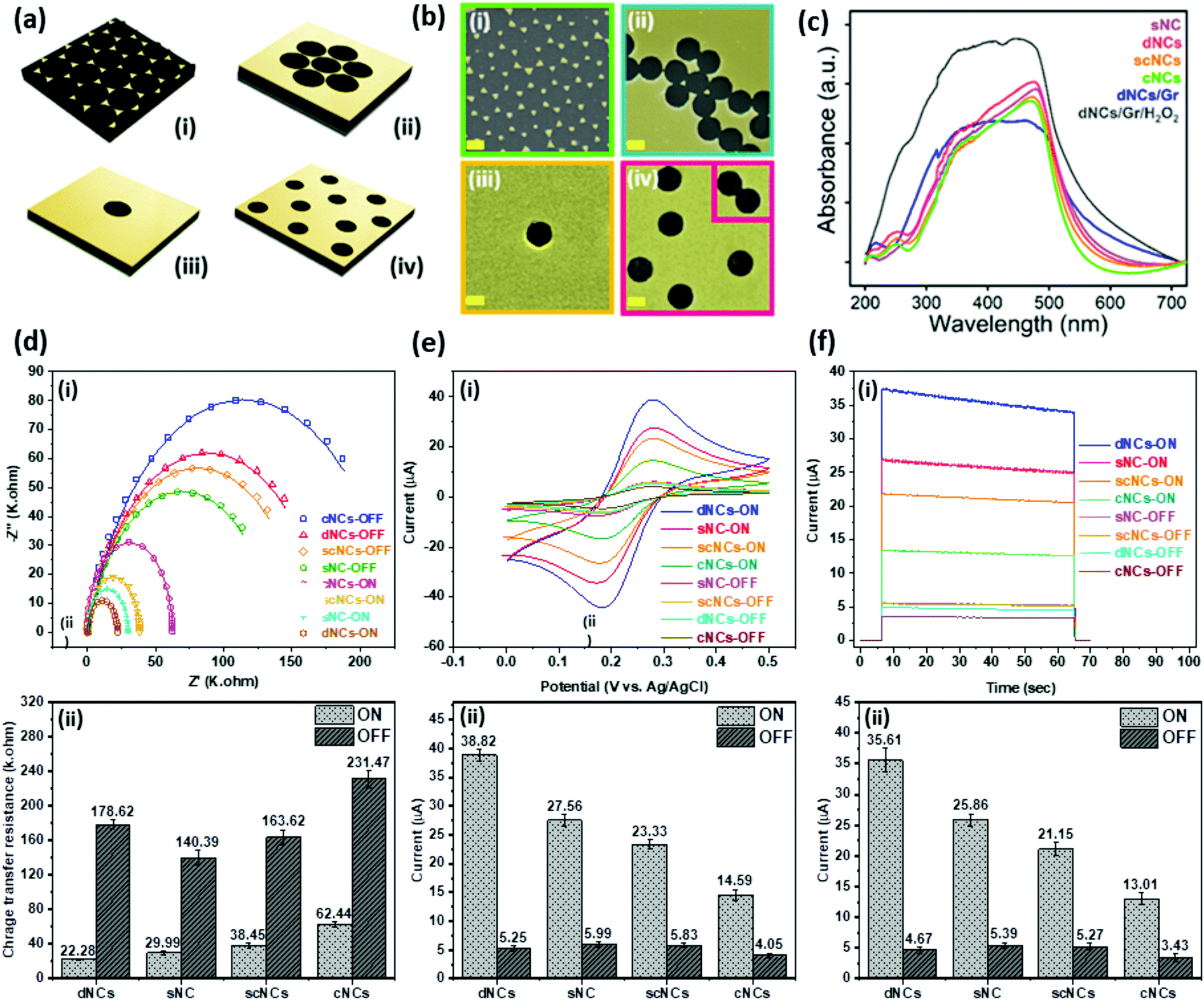 | ||
| Fig. 2 Nanocavity optimization and electrochemical characterization. (a) 3D models of the four NC distributions studied: (i) compact nanocavities (cNCs), (ii) semi-compact nanocavities (scNCs), (iii) single nanocavities (sNC), and (iv) optimally dispersed nanocavities (dNCs), the inset shows a double cavity defect. (b) FE-SEM images of all distributions. All scale bars are 500 nm (c) UV-vis spectra of the four distributions, dNCs/Gr and dNCs/Gr under the highest concentration of H2O2. From top to bottom: dNCs/Gr/H2O2, dNCs, sNC, scNCs, cNCs, and dNCs/Gr. The intensity of the plasmonic peak (at ∼500 nm) is given by a combination of the gold deposited effective surface area and the nanocavity structure distribution which enhances the gold plasmonic effect through LSPR. (d–i) EIS of the four distributions and current responses (e–i) CV and (f–i) CA both under dark and visible light illumination conditions. Bar graphs for (d–ii) charge transfer resistance (e–ii) CV and (f–ii) CA comparing the currents of the optimally dispersed NC distributions. The CV study was performed at a scan rate of 20 mV s−1 and the CA study was carried out at a fixed potential of 0.3 V vs. Ag/AgCl. Both studies were performed in 3 mM K3FeCN6. | ||
Fig. 2b-i–iv show the FE-SEM images of all four possible and recognized configurations of nanocavities on the surface of the electrode. The plasmonic effect of each was assessed by UV-vis spectrometry. The absorbance spectra (Fig. 2c) show that the highest intensity of the plasmonic peak (≈475 nm) is attributed to the optimally dispersed nanocavities (dNCs), followed by the single nanocavity (sNC), the semi-compact nanocavity (scNCs), and the compact nanocavities (cNCs). The plasmonic effect of each was assessed by UV-vis spectrometry. The absorbance spectra (Fig. 2c) show that the highest intensity of the plasmonic peak (≈ 475 nm) is attributed to the optimally dispersed nanocavities, followed by the single nanocavity (sNC), the semi-compact nanocavities (scNCs), and the compact nanocavities (cNCs). A deep correlation between large electromagnetic fields and spectral absorption peaks has been reported before.45 In the case of nanostructured cavities the maximum absorption peak of the electromagnetic field was present at the nanohole edges.45 The gold plasmon resonance is enhanced due to the LSPR present at the nanocavity edges45 (as demonstrated in the FDTD simulation in the next section). The higher the density of the nanocavities the higher the LSPR effect is. Moreover, periodicity modulation can increase and maximize the electrode's response.45 Thus, highly dense, well-distributed multiple nanocavity-patterned electrodes have a higher plasmonic effect than a single nanocavity configuration, a configuration with semi-compact nanocavities or with compact nanocavities. Zheng further explains how excess etching and larger defects, which alter the patterns, produce dimer optical properties.45 This can be observed on the semi-compact nanocavities and compact nanocavity configurations, where the plasmonic peak reduction (≈9–12%) is attributed to the larger amounts of gold removed from the electrode during the lift-up step, in turn generating larger defect cavities with less LSPR and therefore less absorption.
The interfacial charge transfer of the four configurations of nanocavities was studied via electrochemical impedance spectroscopy (EIS) under the presence and absence of visible light illumination and the corresponding equivalent circuits. The resulting Nyquist plots for a single nanocavity, optimally dispersed nanocavities, semi-compact nanocavities, and compact nanocavities under the presence and absence of visible light illumination are shown in Fig. 2d–i.
The semicircle characteristic of the Nyquist plot at higher frequencies is attributed to the electron-transfer limited process (Rct).46 In the equivalent circuit (shown in the inset Fig. 3e–i), the Rct controls the kinetics of the electron transfer at the interface, varying in diameter according to the absorption of different molecules. The Rs represents the resistance of the electrolyte and is defined from the starting point of the spectrum. The double-layer type capacitance of the electrode–electrolyte interface is denoted as Cdl. Comparing the impedance performance of a single nanocavity, optimally dispersed nanocavities, semi-compact nanocavities, and compact nanocavities in the dark and under illumination revealed that all four configurations under light illumination present a drastic reduction in the charge transfer resistance (Fig. 2d–ii). This reduction suggests an enhanced separation efficiency of charges under light illumination.47 Furthermore, among the different configurations under light illumination, the optimally dispersed nanocavities presented the lowest transfer resistance. The higher electrocatalytic activity displayed by nanocavities is attributed to surface-enhanced charger mobility.47 The electrocatalytic effect of the four configurations of nanocavities can be studied through cyclic voltammetry (CV) and chronoamperometry (CA) response to 3 mM K3FeCN6 under dark and visible light illumination conditions (Fig. 2e–i, 2e–ii, 2f–i and 2f–ii). CV measurements of the four configurations were evaluated from −0.1 to 0.5 V at a scan rate of 20 mV s−1. All samples (Fig. 2e–i) show two characteristic peaks at ∼0.3 V in the forward scan and at ∼0.2 V in the backward scan. Noticeably, the optimally dispersed nanocavity distribution shows the highest current response among them under both light and dark conditions. This is the result of the electrocatalytic properties of the electrodes directly attributed to the amount of gold found at the electrode's surface. Furthermore, as the electrode enhancing effect combines both gold electrocatalytic properties and the nanocavity LSPR, the defective double cavities, sporadically created by the lift-up of a pair of cluster beads found at the optimally dispersed nanocavity distribution, were structurally compared to a single nanocavity. The values for both double and single nanocavity perimeter and the area were obtained by SEM with the Fiji ImageJ software image. The ratios of perimeter/area were found to be almost the same (14% difference). Hence, the occasional double cavities are not expected to present a significant impact on the electrode's electrocatalytic properties and LSPR generation. Moreover, the current response of the four electrodes under visible light illumination is enhanced up to ≈7 times (Fig. 2e–ii), in comparison with its response under the dark condition. The results confirm the boosting effect of light irradiation on electrocatalytic properties.47 Furthermore, the response of the optimally dispersed gold nanocavity configurations under visible light illumination, again outperformed other configurations by clearly presenting a higher current (38.82 μA) (Fig. 2e–ii), followed by the single nanocavity (27.56 μA) the semi-compact nanocavities (23.33 μA), and the compact nanocavities (14.59 μA). These results indicate that the nanocavity is a catalytically active site, which explains why a high density distribution of nanocavities has superior plasmonic electrocatalytic properties over the other three configurations where the plasmonic effect is weaker, as seen in the UV-vis analysis. Our results agree with previous reports in the literature, where superior photocatalytic activities have been attributed to the plasmonic enhancement from strong SPR absorption in the visible light region and its conversion into transferrable plasmonic energy.47 To study the transient current, CA response was recorded at a 0.3 V potential, Fig. 2f–i and 2f–ii shows the change in current densities for the four configurations of nanocavities under visible light and dark conditions recorded for 60 s. As expected, the readings of all four presented higher current densities under light illumination. Once again, the optimally dispersed gold nanocavity configuration presents the highest electrocatalytic activity, demonstrating a robust readout system for sensing applications.
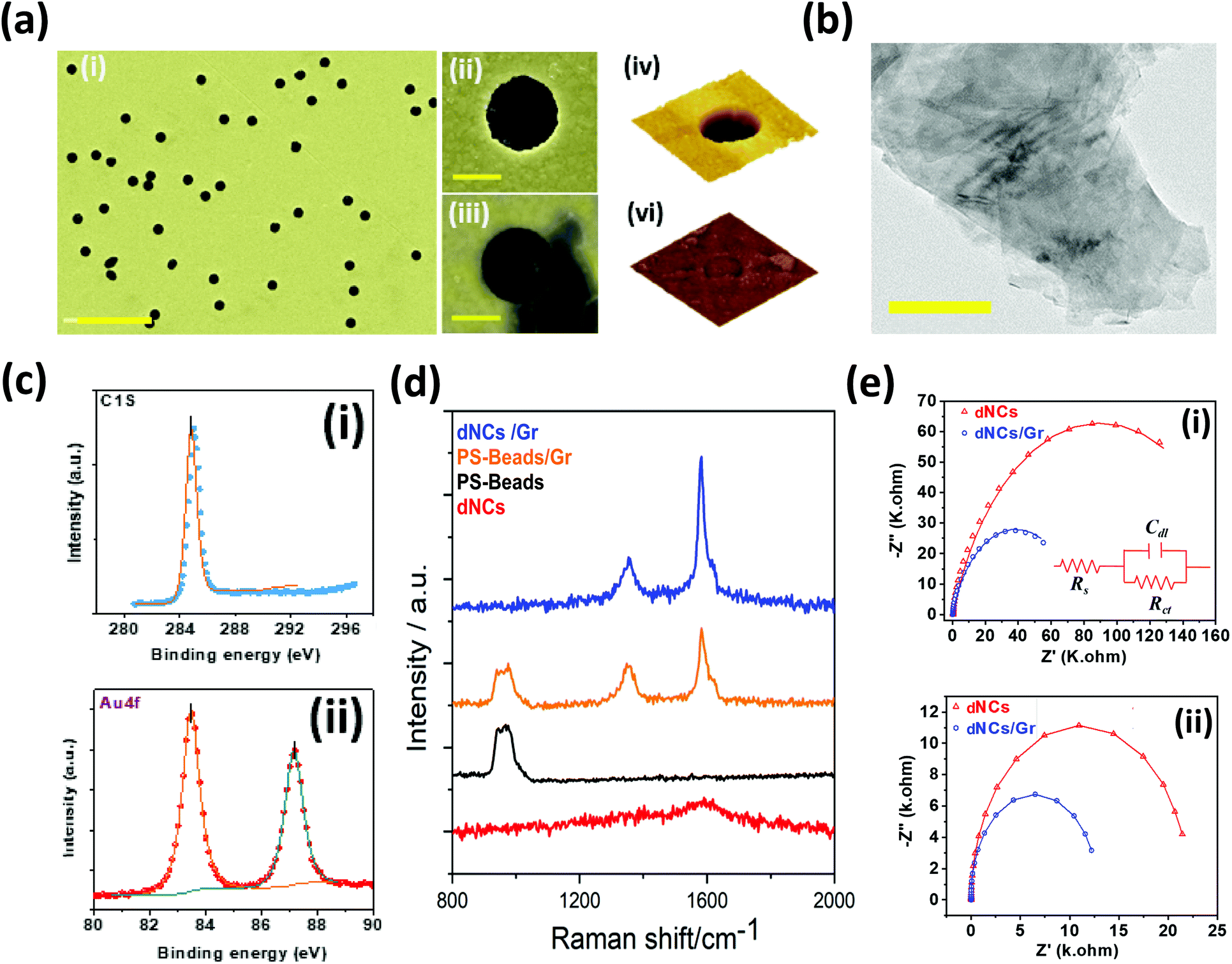 | ||
| Fig. 3 Electrode optimization and characterization. (a) (i) FESEM image of the electrode surface (scale bar 5 μm), (ii) nanocavity, (iii) nanocavity partially covered by a thin graphene sheet (dNCs/Gr) (scale bar: 500 nm), AFM 3D model of a (iv) sNC and a (v) sNC partially covered by graphene. (b) HRTEM image of the Gr nanosheet. (c) XPS analysis of high-resolution scans of dNCs/Gr corresponding to the (i) C1S and (ii) Au4f, respectively; (d) Raman spectra of gold dNCs(red), gold-coated PS-beads (black), gold-coated PS-beads/Gr (orange) and gold dNCs/Gr (blue). (e) EIS of dNCs and dNCs/Gr (i) in the dark, where the inset shows the equivalent circuit, and (ii) under illumination. | ||
Structural and physical properties of nanocavities/Gr electrodes
To improve the sensitivity of the electrode (dNCs) towards H2O2, graphene was introduced into the system to enhance the electrical properties. The morphology of Gr nanosheets and the uniform distribution play a critical role in the electrode performance.4,7,16 We used an established exfoliation and drop-cast approach48 for a more uniform distribution of graphene nanosheets on the nanopatterned surface. The distribution of the graphene nanosheets on the plasmonic nanocavities was studied using FE-SEM. Surface characterization reveals the presence of self-organized optimally dispersed nanocavities, with the same diameter as the beads, after the beads’ removal (Fig. 3a-i–ii) and partial coverage of the cavities with graphene nanosheets (Fig. 3a-iii). The electrode surface was also characterized through AFM, confirming the partial coverage of the nanocavity with graphene (Fig. S2†). The 3-D AFM visualization of a single nanocavity (Fig. 3a-iv) and that of a nanocavity partially covered with graphene sheets is presented in Fig. 3a-v. We used Gwyddion software to measure the depth of the nanocavities from the AFM images, which corresponded to the height of the Au deposited layer (0.06 μm). The HRTEM characterization allowed the study of the degree of exfoliation and quality of the Gr nanosheets. The HRTEM image showed in Fig. 3b displays a few layers of Gr nanosheets, which demonstrates high quality of the nanosheets achieved through the liquid exfoliation technique. In the following section, we discuss the enhanced optical/physical properties of the hybrid structure of optimally dispersed gold nanocavities and graphene nanosheets in comparison with flat gold electrodes as an important parameter in plasmon-assisted electrochemical sensors. To investigate the plasmon-assisted sensing performance of the electrode, the photoactivity parameters were studied. The UV-vis spectroscopy was conducted to experimentally investigate the absorbance UV-vis spectrum associated with the surface plasmonic effect of optimally dispersed gold nanocavities after the drop-casting of graphene on the surface of the electrode. The absorbance spectrum of gold dNCs and gold dNCs/Gr are shown in Fig. 2c (the red and blue lines respectively) confirm the prevalence of the desired absorbance peak of Au at ∼480 nm before and after the graphene drop-casting. The peak observed at ∼265 nm in the optimally dispersed gold NC spectrum is damped due to graphene absorption at this wavelength. The target analyte in this work, H2O2, is highly corrosive with a possible impact on the plasmonic properties of the electrode. We employed UV-vis spectroscopy to study the absorbance spectrum associated with the surface plasmon of the dNCs/Gr electrode in the presence of H2O2, (Fig. 2c-dNCs/Gr/H2O2). As shown in Fig. 2c, no significant change in the shift of the absorbance peak of Au is observed across the spectrum, ensuring the stability of the plasmonic effect and the accuracy of the readings. Moreover, a direct dependence between the H2O2 presence and concentration (ESI note 1, Fig. S3†) and the absorption intensity is ascribed to the electrode's plasmonic properties.49,50XPS analysis was performed to study the surface chemistry of the optimally dispersed nanocavities/graphene (dNCs/Gr) electrode. Fig. 3c shows the high-resolution scans of gold dNCs/Gr in the region of the characteristic peaks of C1s and Au4f. Fig. 3c-i demonstrates the successful formation of Gr by drop-casting, as evidenced by the appearance of the C1s peak. As expected, the two characteristic peaks of metallic gold are observed in the Au4f (Fig. 3c-ii) spectra at a binding energy of 83.56 eV (Au 4f7/2) and 87.24 eV (Au 4f5/2). Raman spectroscopy is an essential characterization tool for studying carbon-based materials and providing a structural fingerprint of the proposed electrode. Fig. 3d shows the result of Raman spectroscopy for optimally dispersed sNCs/Gr electrodes. The samples were excited with a 532 nm laser and measured with a 50× objective. The first three layers including the Si wafer, the ZnO spacer, and the Au metal film are considered as the baseline for our electrode, showing a vague peak at ∼1590 cm−1. The nanocavity formation can be monitored by two methods. First, by comparing the Raman spectroscopy results of the electrode before and after bead removal. The Raman characteristics of the self-assembled polystyrene (PS) beads show a peak near the reported peak at 1000 cm−1 (ref. 51) (black spectra in Fig. 3d). After the lift-off process and removing the beads to purposefully create the nanocavities, the PS peak disappears from Raman spectra as shown by the red spectrum in Fig. 3d for dNCs. The disappearance of the peak demonstrates the effective removal of the beads, which corresponds to a nanocavity formation (Fig. 3d-dNCs). According to the literature, graphene has a well-documented characteristic spectrum with two bands, the disorder (D), and the graphitic (G) at ∼1353 cm−1 and ∼1582 cm−1 respectively.7,52 These two identification peaks of graphene are clearly recognized in the Raman spectrum of the optimally dispersed NC/Gr electrode (blue line in Fig. 3d dNC/Gr). The second method compares the Raman spectrum of Gr/PS before lift-off (orange spectrum in Fig. 3d) with that of graphene/nanocavities (blue line in Fig. 3d), the intensity ratio between graphene D and G band (ID/IG) is decreased in the presence of the gold nanocavities, indicating a weaker attachment to the nanocavity-patterned electrode compared to the sphere patterned electrode.48 The weaker attachment of graphene nanosheets onto the gold nanocavities electrode is due to the graphene sheets’ location, being partially in contact with the gold layer and partially floating on top of the nanocavity. The partial floating of the Gr nanosheets would facilitate Gr free electrodes to interact with the analyte.24,43,48 In the following section with the help of FDTD simulation, we will discuss the role of optimally dispersed plasmonic gold nanocavities in the enhancement of the optoelectrical properties.
The proposed sensor employs an electrochemical approach under visible light illumination as the read-out system, which is greatly affected by the plasmonic electrochemical properties of the optimally dispersed nanocavity electrodes. The interfacial charge transfer of the gold dNCs and gold dNCs/Gr electrodes was characterized by electrochemical impedance spectroscopy (EIS) in the presence and absence of visible light illumination and the corresponding equivalent circuits. Fig. 3e and the insets show the resulting Nyquist plots of gold dNCs and gold sNCs/Gr and the equivalent circuits in the presence and absence of visible light illumination. Comparing the impedance performance of gold dNCs and gold dNCs/Gr in the dark (Fig. 3e-i) and under illumination (Fig. 3e-ii) revealed that the plasmonic assisted electrochemical electrode displays higher electrocatalytic activity, reducing the resistivity by more than 70%. The results suggest that the graphene's superb electron mobility enhances the electron transfer of the plasmonic optimally dispersed nanocavities under visible light illumination, which is shown by a sharp decrease in the resistivity of the dNCs from 22.27 k Ohm to 12.85 k Ohms dNCs/Gr by the addition of Gr. Our previous studies suggest that the low resistivity is attributed to the extra photo-induced charges generated through light irradiation in comparison with the dark conditions.43,53
Theoretical studies of the plasmonic response of nanocavities
To analyze the effect of nanocavities and graphene sheets on the plasmonic response of the platform, Finite-Difference Time-Domain (FDTD) simulation is performed (Fig. 4). Based on our experimental conditions, four layers are considered including 500 nm SiO2_glass, 100 nm ZnO, 60 nm gold, and 5 nm graphene sheet. Also, the nanocavities are designed using spheres with a predefined “etch material” (ESI note 2, Fig. S4†). The graphene sheet is included by adding a 5 nm thick graphene square on top of the nanocavity. The size of the square side is equal to the nanocavity diameter to fully cover the nanocavity. Fig. 4d shows the 2D contour of the electric field for a single nanocavity covered with a graphene sheet at different light source frequencies. At a low wavelength (535 nm), the electrical field is mostly concentrated at the center of the cavity. By increasing the frequency, the resonance effect leads to a relatively high electrical field at the interface of gold and zinc oxide interface at the edges of the cavity. The maximum value of the absolute electrical field is depicted in Fig. 4b for different types of platforms including the bare surface without nanocavities and graphene, single nanocavity (sNC), and nanocavity partially covered by a thin graphene sheet (sNCs/Gr). The created nanocavity considerably increases the maximum electrical field magnitude in the center of the cavity. In higher wavelengths (>550 nm), the electrical field will be concentrated at the edges of cavities. This local electrical field is due to plasmonic resonance at the edges of the cavity which increases the charge transfer rate and consequently enhances the sensibility of detection. In addition, the graphene sheet (sNCs/Gr) enhances the magnitude of the localized electric field. The effect of the cavity size on the maximum electrical field inside the channel is observed for the cavities smaller than 1000 nm (Fig. 4c). The maximum electrical field which is observed at the wavelength of 600–650 nm, has an optimum value for around 700 nm size cavities. In Fig. 4a, the broad-band absorption intensity spectra of a single cavity with and without graphene show a good agreement with the experimental results.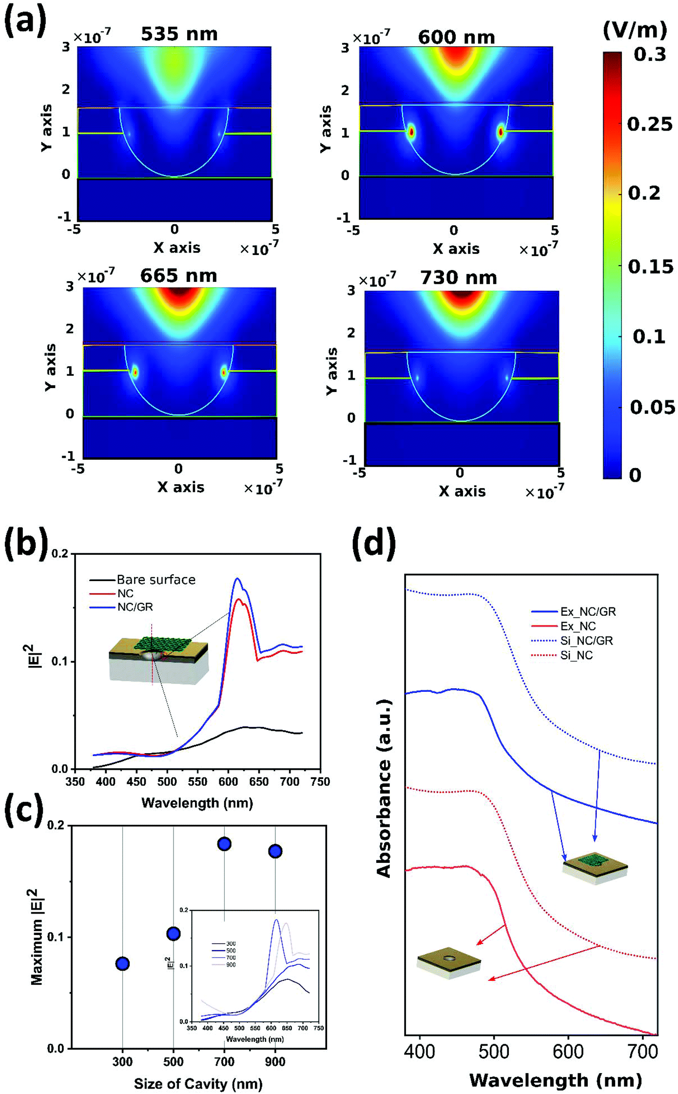 | ||
| Fig. 4 FDTD simulation of surface intensity absorbance and electrical field of the proposed platform. (a) The 2D contour of the maximum value of the absolute electrical field in the three platforms in the broadband wavelength. (b) Maximum of the absolute electrical field in the three platforms in broadband wavelength. (c) The maximum electrical field for different sizes of the cavity. (d) Experimental and simulation comparison of absorbance of platforms with and without graphene. | ||
Plasmon-assisted electrochemical hydrogen peroxide detection
Cancer cells continuously release H2O2 in larger quantities compared to normal cells, yet the monitoring of small variations in the amounts of released H2O2 is still challenging to date for sensors and biosensors. In this study, we first verified the suggested superior properties of the optimally dispersed nanocavity electrode. For this purpose, a simple CA test comparing the performance of all electrode nanocavity configurations without (Fig. S5a†) and with graphene (Fig. S5b†) towards the detection of H2O2 was conducted. After the confirmation on the remarkable response of optimally dispersed nanocavity electrode, outperforming the other nanocavity configurations by at least ≈30% higher signal readout in the presence of the analyte, a linear range of sensitivity and limit of the detection (LOD) were established. Along with a selectivity study, all tests were performed in a biological buffer via a CA test under visible light illumination. Fig. 5a and b compare the plasmonic electrochemical response of the gold nanocavity electrodes with and without graphene in the presence and absence of 1 mM H2O2 in PBS (pH = 7.4). While the optimally dispersed gold nanocavity electrode shows a plasmonic electroactive response in PBS (pH = 7.4), it suffers from a lack of sensitivity towards H2O2 (Fig. 5a). As mentioned previously, the direct reduction of H2O2 requires a high overpotential, limiting the use of conventional electrodes such as flat gold.54 The results from the extensive study on the electrochemical properties of different configurations of nanocavities (Fig. 2), revealed that nanocavities act as a catalytically active site. The modulation of the density and distribution of the nanocavities allows us to tune the separation efficiency of charges under light illumination. Moreover, the fabrication of an electrode with a high density of NCs increases the absorption of visible light as well as the transferrable plasmonic energy.47 Hence, the optimally dispersed nanocavity configuration is ideal to couple with the superb properties of Gr, which can further enhance the properties of the electrode. Thus, after the addition of Gr, the gold dNCs/Gr electrode demonstrates (Fig. 5b) improved properties combining excellent electroactivity and high sensitivity towards H2O2.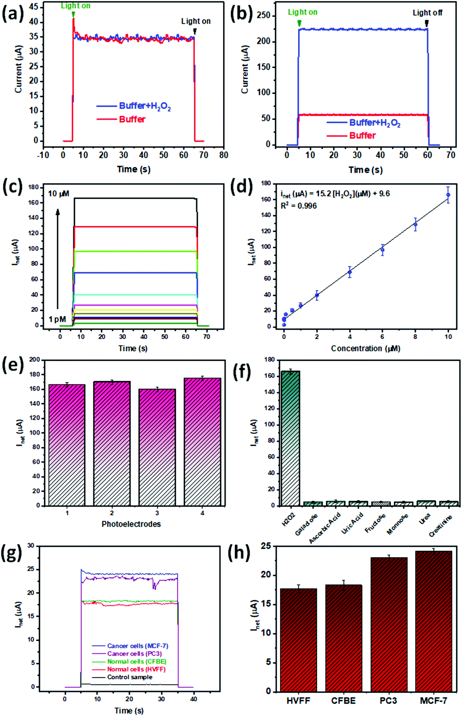 | ||
| Fig. 5 Chronoamperometry test and real sample experiments. Response in a buffer and in the presence of 1 mM H2O2 for dNCs (a) and dNCs/Gr (b) electrodes. Different low concentrations of H2O2 in PBS (1× dilution, pH = 7.4) as low as 1 pM were tested, as well as a high concentration of 10 μM (c), forming a linear range (d). Repeatability (e) and selectivity (f) of the proposed electrode towards H2O2. (g) Photocurrent results and (h) the correspondence current of dNCs/Gr in plasma and in the presence of cancer and non-cancer cells. | ||
There are studies on surface modification or addition of materials with superior electrical properties, such as carbon-based materials, to boost the electrochemical sensors’ sensitivity.55 In this study a dual mechanism is proposed to be responsible for the enhanced H2O2 detection, comprising the interaction of gold with Gr and the effect of the Gr nanosheet section suspended on top of the nanocavity hole. Gr's superb catalytic properties and superior conductivity of electrical charge enhance the charge transfer necessary for the detection of H2O2 reduction.16,56 The literature suggests that the heterogeneous transfer of electrons occurs at graphene's edges or basal plane defects. Herein, graphene's extended surface area provides numerous electroactive sites for electron transfer.57,58 Where the electrodes can be distributed in between the interface of the materials, extending the hot electron lifetime.59 Further enhancement of plasmonic electrochemical sensing can be achieved by using the nanocavities/Gr interaction. Recent studies on hollow structures underneath Gr have reported an enhancement of Gr plasmonic absorption, attributed to the strong surrounding electric field generated by LSPR.60 Moreover, Gr interaction with hollow structures was reported to enhance the current density associated with the reduction of H2O2 attributed to the structure's effective surface area.61 Graphene-based materials, such as quantum dots, have been reported in the literature to be able to stimulate the production of singlet oxygen when excited at specific wavelengths.62,63 On their end, graphene nanosheets have been reported to temporarily enhance the collection of energy and intensity of the plasmonic effect.64 This same study has reported that the plasmon resonance can activate oxygen to a triplet excited state and that graphene in turn can oxidize grounded oxygen to triplet-excited oxygen which is then transferred to the plasmonic surface.64 This synergistic mechanism is believed to play a highly important role in the underneath mechanism of plasmon-driven catalytic reactions.64 Given that our approach is based on photosensitivity in the visible light range the above mechanism could be responsible for the enhancement of the catalytic effect, which would then actually be beneficial, being partially responsible for the enhanced response of the dNCs/Gr electrode proposed here.
The optimally dispersed nanocavities/Gr electrode response towards H2O2 was measured through CA. As Fig. 5c shows the net current, increases along with the increment of the H2O2 concentrations (1 pM–10 μM). The optimally dispersed nanocavities/Gr electrode presents a superb limit of detection of 1 pM in a linear range of 1 pM–10 μM and a sensitivity of 1520 μA mM−1 cm−2 and a R2 = 0.988 (Fig. 5d). The reproducibility of the optimally dispersed nanocavities/Gr electrode was assessed through a CA test of the electrode in the presence of 10 μM H2O2 in PBS. As shown in Fig. 5e, the measurements and error bars confirm good repeatability of the electrode with a relative standard deviation (RSD) lower than 5%. After conducting the repeatability experiment a tolerance of ±1 μA should be considered for all measurements. As shown in Table S1,† our proposed plasmon-assisted electrochemical sensor based on the optimally dispersed nanocavities/Gr electrode shows 1 pM as LOD. The superb LOD of our electrode is, to the best of our knowledge, the lowest reported to have a wide linear range in a low concentration range.
Biological fluids are complex and contain diverse analytes that could potentially contaminate or interact with our sensing electrode. To develop a robust sensor, it is imperative to assess the reaction of the target analyte with other natural interferants. As a ROS species, H2O2 is prone to interference from multiple co-existing molecules. The most reported interfering analytes for H2O2 are ascorbic acid (AA) and uric acid (UA).65,66 Additionally, H2O2 relation to oxidase enzymes encourages the study of galactose, fructose, and mannose as interferants.67 Other possible interfering substances that can be found in biological samples, such as blood, are urea and creatinine, which are also studied. A selectivity study of our proposed plasmon-assisted electrochemical sensor towards H2O2 was performed by assesing the individual photocurrent response of the sensor to the precense of different biological species. The interfering analytes were evaluated at 0.1 mM under a cathodic potential of −0.3 V. The results shown in Fig. 5f indicate no significant change in the photocurrent across the interfering solutions, implying a high selectivity of our optimally dispersed gold nanocavities/Gr towards H2O2. The high selectivity is attributed to the potential used for H2O2 detection in the chronoamperometric test, which differs from the potential of other possible biological interferant active molecules.55 Furthermore, compared to other studies,54 we apply less potential, save energy while avoiding background noise.
It should be noted that although at the nanoscale the electrode exhibits excellent performance and great repeatability, at a macroscale, the Gr nanosheets can detach from the electrode's surface after the completion of the measurement. The possible separation is associated with the weaker adherence of graphene nanosheets on the electrode, as previously suggested by the ID/IG ratio of the Raman spectrum.48 However, this does not represent a major setback since the proposed electrode was designed to be a one-time sensing device and not for multiple experiments.53 Despite being a disposable electrode, the confidence of the quantitative measurement needs to be demonstrated, thus, the repeatability and stability study were performed.68,69 The repeatability study discussed above with an RSD of less than 5% is sufficient for a disposable approach.53,68,70–72 The study of the long-term stability of the electrode readout can be assessed by consecutive measurements.48,68 A long-run stability study (Fig. S6†) was performed by a 30 min CA experiment for a bare gold surface with graphene (blue), an optimally dispersed gold nanocavity (black), and for the proposed optimally dispersed gold nanocavity/Gr electrode (red). As observed in Fig. S6† after 30 min the current was reduced to 29.5%, 1.37%, and 21.47%, respectively. Still, all the CA measurements were performed in less than 1.5 min, thus we are confident of the veracity of the data collected. The electrode performance after an extended storage period was assessed by studying its performance after 4 months of storage at room temperature. Afterwards, the optimally dispersed nanocavity/Gr electrode retains ≈95% current response, confirming long-term stability overperforming other graphene-based electrodes.72,73 The signal loss after storage is not considered a limitation for the proposed electrode. Overall, there are two limitations of the proposed electrode: (i) the discussed weaker interaction between the gold surface nanopatterned with the dNCs, which increases the chances of Gr detachment48 and (ii) the Gr nanosheets and the minor variability that the randomization of the Gr distribution can introduce to the system. Still, the stability and repeatability presented by the electrode are acceptable for a one-time use approach.53,68
Real sample study
The principal objective of the proposed plasmon-assisted electrochemical sensor is the detection of small changes in H2O2 concentrations released by human cells. As a first step towards the study of real conditions, a biological buffer was used for the sensing of the analyte. After effective detection of H2O2 spiked in human plasma through a chronoamperometric test (Table S3†), an experiment for direct detection of H2O2 from human cells in plasma was performed (Fig. 5g). As proof of concept, the electrode was studied with cancer cell lines MCF-7 and PC3 and two healthy cell lines CFBE and hVFF. Among, MCF-7 and CFBE are epithelial cell types, while PC3 presents an epithelial morphology. There are studies found in the literature reporting the difference in H2O2 as being cell state-specific6,44 To stimulate the release of H2O2 from the cells 1000 ngr per ml of PMA was added prior to measurement. As shown in Fig. 5h the current density increases from ≈15 μA to nearly 25 μA from the non-cancer cell sample to the cancer cell measurement. Furthermore, when the test is run with the cancer cells, MCF-7 or PC3, there is a minimum increase of ≈26% in the readings compared to fibroblast and epithelial cells. The total concentrations of H2O2 were calculated using the calibration curve in Fig. S7,† the values in Table S2† show that the cancer cells release at least ≈3.8 times more H2O2, confirming the augmented production of H2O2 of cancer cells over healthy cells. The measurements agree with previous reports on the literature regarding the individual release of H2O2 from cancer cells (using the calibration curve in Fig. S7,† concentrations were calculated to be: 2042 fM for MCF-7, 1767 fM for PC3, 464 fM for epithelial, and 350 fM for fibroblast) as shown in Table S2.† The study of the cell's media wettability before and after PMA stimulation suggested that the increase in hydrophilicity is attributed to the release of the hydrophilic H2O2 (Fig. S8†).74 To further assess the feasibility of our proposed electrode in a real scenario we run a recovery test (Table S3†). The results in the spiked solutions indicated a range of 91–120%, with an RSD value of 5%, which indicates an exceptional recovery rate in human plasma samples.Conclusion
In this study, after a thorough characterization of the nanocavity formation and possible configurations, the optimally dispersed nanocavity configuration was selected as ideal for its remarkable optical and electrochemical properties. Through our fabrication method, the nanocavity distribution achieves ≈80% of single nanocavities. We demonstrate that the combined plasmonic effect of optimally dispersed nanocavity nanostructures and Gr superb electrical properties results in the development of a highly sensitive electrode for the detection of low concentrations of H2O2 based on plasmon-assisted electrochemical sensing. Theoretically, we studied the electrical field and charge transfer properties of the proposed electrode under visible light illumination, where the FDTD simulation shows the intensity of charge distribution at the edges of the optimally dispersed gold nanocavities/Gr. This enhances its sensitivity by increasing the charge transfer rate. Using characterization techniques, such as FE-SEM, HRTEM, AFM, UV-vis, and Raman spectroscopy, it was demonstrated that the simple fabrication technique resulting in patterned optimally dispersed gold nanocavities/Gr enhances the electrode conductive properties. Our electrochemical studies revealed that with the proper coupling of Gr with gold nanocavities the plasmonic effect is essential for achieving a higher current and reduced charge transfer resistance, which is crucial for the success of the plasmon-assisted electrochemical electrode read-out system. We successfully implemented the proposed electrode and integrated it with a controlled fluidic sample delivery system in a microfluidic device for the determination of H2O2 concentration in a portable fashion. The proposed optimally dispersed gold nanocavities/Gr electrode is capable of sensing down to 1 pM of H2O2 (LOD) in a low concentration linear range of 1 pM–10 μM, confirming the superb conductive properties of the electrode. Additionally, the selectivity study revealed the high affinity of the electrode towards H2O2. We confirmed the ability of the proposed electrode to detect the analyte in PBS and plasma. Specifically, the current density increased from the non-cancer cell sample (≈15 μA) to ≈25 μA reached by MCF-7 and PC3 cancer cells. Thus, the H2O2 released allows the differentiation between non-cancer and cancer cells, since non-cancer cells, hVFF, and CBFE present 26% lower current density compared to MCF-7 and PC3 cancer cell lines, confirming that the cancer cells increase the production of H2O2. Through a series of wettability studies, we demonstrated that the release of H2O2 leads to an increase in the hydrophilicity. In conclusion, this study presents a novel plasmon-assisted electrode for the detection of low concentrations of H2O2 with a superb low LOD and high selectivity. The proposed microfluidic device has the potential for automation for rapid determination of H2O2 concentration in biological environments and quick cancer diagnosis, providing the possibility for simple fabrication, cost-effective, and highly specific point-of-need application.Author contributions
SM and RSM, conceived the idea. CdRM, RSM, and MJ fabricated the electrodes. CdRM and RSM designed, planned, and conducted the investigation, including all characterization and optimization. IIH performed the theoretical study via design and implementation of a FDTD simulation. CdRM prepared and maintained all cell culture materials. CdRM and RSM curated and analyzed the data, with the input of MJ. Under the supervision of SM, and with the input of all authors, CdRM and RSM prepared the manuscript.Conflicts of interest
The authors have no conflicts to declare.Acknowledgements
The authors thank the Faculty of Engineering at McGill University, the Natural Science and Engineering Research Council of Canada (NSERC, G247765) and the Canada Foundation for Innovation (CFI, G248924) for financial support. Carolina del Real Mata thanks CONACYT for scholarship funding (924317). The authors also want to acknowledge McGill University, Nanotools-Microfab Facility for Electron Microscopy Research and NanoQAM facilities at Université du Québec à Montréal. The authors would like to thank CMC Microsystems for CAD tool support.References
- C. Alix-Panabieres, Nature, 2020, 579, S9 CrossRef CAS PubMed.
- M. Jalali, I. I. Hosseini, T. AbdelFatah, L. Montermini, S. Wachsmann-Hogiu, J. Rak and S. Mahshid, Lab Chip, 2021, 21, 855–866 RSC.
- L. Li, Y. Zhang, L. Zhang, S. Ge, H. Liu, N. Ren, M. Yan and J. Yu, Anal. Chem., 2016, 88, 5369–5377 CrossRef CAS PubMed.
- Y. Zhang, X. Bai, X. Wang, K. K. Shiu, Y. Zhu and H. Jiang, Anal. Chem., 2014, 86, 9459–9465 CrossRef CAS PubMed.
- M. Labib, E. H. Sargent and S. O. Kelley, Chem. Rev., 2016, 116, 9001–9090 CrossRef CAS.
- D. Trachootham, J. Alexandre and P. Huang, Nat. Rev. Drug Discovery, 2009, 8, 579–591 CrossRef CAS PubMed.
- S. Wang, Y. Zhu, X. Yang and C. Li, Electroanalysis, 2014, 26, 573–580 CrossRef CAS.
- H. Guan, J. Zhang, Y. Liu, Y. Zhao and B. Zhang, Electrochim. Acta, 2019, 295, 997–1005 CrossRef CAS.
- C. Liu, Y. Ding, Q. Li and Y. Lin, Microchim. Acta, 2017, 184, 2497–2503 CrossRef CAS.
- Q. Xin, Q. Liu, H. Shah and J. R. Gong, Analyst, 2017, 142, 316–325 RSC.
- Y. Sheng, H. Yang, Y. Wang, L. Han, Y. Zhao and A. Fan, Talanta, 2017, 166, 268–274 CrossRef CAS PubMed.
- P. Chandra, Nanobiosensors for personalized and onsite biomedical diagnosis – eBook 2016 London : Institute of Engineering and Technology, 2016, DOI:10.1049/PBHE001E.
- S. S. Mahshid, S. E. Flynn and S. Mahshid, Biosens. Bioelectron., 2021, 176, 112905 CrossRef CAS PubMed.
- W. Dang, Y. Sun, H. Jiao, L. Xu and M. Lin, J. Electroanal. Chem., 2020, 856, 113592 CrossRef CAS.
- F. Khan, N. Akhtar, N. Jalal, I. Hussain, R. Szmigielski, M. Q. Hayat, H. B. Ahmad, W. A. El-Said, M. Yang and H. A. Janjua, Mikrochim. Acta, 2019, 186, 127 CrossRef.
- Y. Sun, M. Luo, X. Meng, J. Xiang, L. Wang, Q. Ren and S. Guo, Anal. Chem., 2017, 89, 3761–3767 CrossRef CAS PubMed.
- Y. Zhang, C. Wu, X. Zhou, X. Wu, Y. Yang, H. Wu, S. Guo and J. Zhang, Nanoscale, 2013, 5, 1816–1819 RSC.
- J. Das, I. Ivanov, L. Montermini, J. Rak, E. H. Sargent and S. O. Kelley, Nat. Chem., 2015, 7, 569–575 CrossRef CAS PubMed.
- S. Mahshid, A. H. Mepham, S. S. Mahshid, I. B. Burgess, T. Saberi Safaei, E. H. Sargent and S. O. Kelley, J. Phys. Chem. C, 2016, 120, 21123–21132 CrossRef CAS.
- L. Wang, W. Zhu, W. Lu, L. Shi, R. Wang, R. Pang, Y. Cao, F. Wang and X. Xu, Biosens. Bioelectron., 2019, 142, 111577 CrossRef CAS PubMed.
- L. Yu, Y. Zhang, Q. Zhi, Q. Wang, F. S. Gittleson, J. Li and A. D. Taylor, Sens. Actuators, B, 2015, 211, 111–115 CrossRef CAS.
- B. Ma, C. Kong, X. Hu, K. Liu, Q. Huang, J. Lv, W. Lu, X. Zhang, Z. Yang and S. Yang, Biosens. Bioelectron., 2018, 106, 29–36 CrossRef CAS.
- C. Wang, X. G. Nie, Y. Shi, Y. Zhou, J. J. Xu, X. H. Xia and H. Y. Chen, ACS Nano, 2017, 11, 5897–5905 CrossRef CAS PubMed.
- M. Jalali, T. AbdelFatah, S. S. Mahshid, M. Labib, A. Sudalaiyadum Perumal and S. Mahshid, Small, 2018, 14, e1801893 CrossRef PubMed.
- A. Sanati, R. Siavash Moakhar, I. I. Hosseini, K. Raeissi, F. Karimzadeh, M. Jalali, M. Kharaziha, S. Sheibani, L. Shariati, J. F. Presley, H. Vali and S. Mahshid, ACS Sens., 2021, 6(3), 797–807 CrossRef CAS PubMed.
- S. S. Wang, X. P. Zhao, F. F. Liu, M. R. Younis, X. H. Xia and C. Wang, Anal. Chem., 2019, 91, 4413–4420 CrossRef CAS PubMed.
- B. Hofmann, E. Kätelhön, M. Schottdorf, A. Offenhäusser and B. Wolfrum, Lab Chip, 2011, 11, 1054–1058 RSC.
- O. A. Yeshchenko, V. Y. Kudrya, A. V. Tomchuk, I. M. Dmitruk, N. I. Berezovska, P. O. Teselko, S. Golovynskyi, B. Xue and J. Qu, ACS Appl. Nano Mater., 2019, 2, 7152–7161 CrossRef CAS.
- M. Lu, H. Zhu, C. G. Bazuin, W. Peng and J. F. Masson, ACS Sens., 2019, 4, 613–622 CrossRef CAS PubMed.
- M. Azimzadeh, M. Rahaie, N. Nasirizadeh, K. Ashtari and H. Naderi-Manesh, Biosens. Bioelectron., 2016, 77, 99–106 CrossRef CAS PubMed.
- Z. Wang and Z. Dai, Nanoscale, 2015, 7, 6420–6431 RSC.
- R. Zhang and W. Chen, Biosens. Bioelectron., 2017, 89, 249–268 CrossRef CAS PubMed.
- K. Chung, A. Rani, J. E. Lee, J. E. Kim, Y. Kim, H. Yang, S. O. Kim, D. Kim and D. H. Kim, ACS Appl. Mater. Interfaces, 2015, 7, 144–151 CrossRef CAS PubMed.
- E. Ko, V.-K. Tran, S. E. Son, W. Hur, H. Choi and G. H. Seong, Sens. Actuators, B, 2019, 294, 166–176 CrossRef CAS.
- E. Ko, V.-K. Tran, Y. Geng, W. S. Chung, C. H. Park, M. K. Kim, G. H. Jin and G. H. Seong, J. Electroanal. Chem., 2017, 792, 72–78 CrossRef CAS.
- M. Yang, D. S. Kim, J. H. Yoon, S. B. Hong, S. W. Jeong, D. E. Yoo, T. J. Lee, S. J. Lee, K. G. Lee and B. G. Choi, Analyst, 2016, 141, 1319–1324 RSC.
- B. Ai, Y. Yu, H. Mohwald, G. Zhang and B. Yang, Adv. Colloid Interface Sci., 2014, 206, 5–16 CrossRef CAS PubMed.
- J. Zhang, Y. Li, X. Zhang and B. Yang, Adv. Mater., 2010, 22, 4249–4269 CrossRef CAS PubMed.
- P. Innocenzi, L. Malfatti and G. J. A. A. Soler-Illia, Chem. Mater., 2011, 23, 2501–2509 CrossRef CAS.
- M. Retsch, Z. Zhou, S. Rivera, M. Kappl, X. S. Zhao, U. Jonas and Q. Li, Macromol. Chem. Phys., 2009, 210, 230–241 CrossRef CAS.
- D. G. Choi, S. G. Jang, S. Kim, E. Lee, C. S. Han and S. M. Yang, Adv. Funct. Mater., 2006, 16, 33–40 CrossRef CAS.
- M. Itano, F. W. Kern, R. W. Rosenberg, M. Miyashita, I. Kawanabe and T. Ohmi, IEEE Trans. Semicond. Manuf., 1992, 5, 114–120 CrossRef.
- M. Jalali, R. S. Moakhar, T. Abdelfattah, E. Filine, S. S. Mahshid and S. Mahshid, ACS Appl. Mater. Interfaces, 2020, 12, 7411–7422 CrossRef CAS.
- H. Dai, Y. Chen, X. Niu, C. Pan, H. Chen and X. Chen, Biosens. Bioelectron., 2018, 118, 36–43 CrossRef CAS PubMed.
- P. Zheng, S. K. Cushing, S. Suri and N. Wu, Phys. Chem. Chem. Phys., 2015, 17, 21211–21219 RSC.
- J. Liu, R. Siavash Moakhar, A. Sudalaiyadum Perumal, H. N. Roman, S. Mahshid and S. Wachsmann-Hogiu, Sci. Rep., 2020, 10, 9527 CrossRef PubMed.
- M. Sun, C. Zhai, J. Hu, M. Zhu and J. Pan, J. Colloid Interface Sci., 2018, 511, 110–118 CrossRef CAS PubMed.
- M. Jalali, E. Filine, S. Dalfen and S. Mahshid, Mikrochim. Acta, 2020, 187, 90 CrossRef CAS PubMed.
- E. Filippo, A. Serra and D. Manno, Sens. Actuators, B, 2009, 138, 625–630 CrossRef CAS.
- E. Fagadar-Cosma, I. Sebarchievici, A. Lascu, I. Creanga, A. Palade, M. Birdeanu, B. Taranu and G. Fagadar-Cosma, J. Alloys Compd., 2016, 686, 896–904 CrossRef CAS.
- O. Peron, E. Rinnert, T. Toury, M. Lamy de la Chapelle and C. Compere, Analyst, 2011, 136, 1018–1022 RSC.
- F. Xiao, J. Song, H. Gao, X. Zan, R. Xu and H. Duan, ACS Nano, 2012, 6, 100–110 CrossRef CAS PubMed.
- R. Siavash Moakhar, T. AbdelFatah, A. Sanati, M. Jalali, S. E. Flynn, S. S. Mahshid and S. Mahshid, ACS Appl. Mater. Interfaces, 2020, 12, 23298–23310 CrossRef CAS.
- S. Zhao, J. Zhang, Z. Li, P. Zhang, Y. Li, G. Liu, Y. Wang and Z. Yue, Microchim. Acta, 2016, 184, 677–686 CrossRef.
- J. Ju and W. Chen, Anal. Chem., 2015, 87, 1903–1910 CrossRef CAS PubMed.
- Y. Liu, F. Chen, Q. Wang, J. Wang, J. Wang, L. Guo and T. T. Gebremariam, Nanoscale, 2019, 11, 8812–8824 RSC.
- M. Pumera, Mater. Today, 2011, 14, 308–315 CrossRef CAS.
- A. T. Lawal, Talanta, 2015, 131, 424–443 CrossRef CAS PubMed.
- C. Liang, Z. A. Lu, J. Wu, M. X. Chen, Y. Zhang, B. Zhang, G. L. Gao, S. Li and P. Xu, ACS Appl. Mater. Interfaces, 2020, 12, 54266–54284 CrossRef CAS PubMed.
- W. Wang, Y. Zhu, H. Zhang, L. Qing, L. Lei, D. Li and J. Yi, Phys. Rev. B, 2019, 99, 235407 CrossRef CAS.
- L. Shang, B. Zeng and F. Zhao, ACS Appl. Mater. Interfaces, 2015, 7, 122–128 CrossRef CAS.
- R. Matshitse and T. Nyokong, J. Fluoresc., 2018, 28, 827–838 CrossRef CAS PubMed.
- J. Ge, M. Lan, B. Zhou, W. Liu, L. Guo, H. Wang, Q. Jia, G. Niu, X. Huang, H. Zhou, X. Meng, P. Wang, C. S. Lee, W. Zhang and X. Han, Nat. Commun., 2014, 5, 4596 CrossRef CAS PubMed.
- J. Zhao, M. Sun, Z. Liu, B. Quan, C. Gu and J. Li, Sci. Rep., 2015, 5, 16019 CrossRef CAS PubMed.
- M. A. Fini and K. R. Stenmark, Eur. J. Intern. Med., 2019, 69, e11–e12 CrossRef PubMed.
- H. Shamkhalichenar and J.-W. Choi, J. Electrochem. Soc., 2020, 167, 037531 CrossRef CAS.
- M. Guler, V. Turkoglu, A. Bulut and M. Zahmakiran, Electrochim. Acta, 2018, 263, 118–126 CrossRef CAS.
- N. Ruecha, N. Rodthongkum, D. M. Cate, J. Volckens, O. Chailapakul and C. S. Henry, Anal. Chim. Acta, 2015, 874, 40–48 CrossRef CAS PubMed.
- J. Mohanraj, D. Durgalakshmi, R. A. Rakkesh, S. Balakumar, S. Rajendran and H. Karimi-Maleh, J. Colloid Interface Sci., 2020, 566, 463–472 CrossRef CAS PubMed.
- P. K. Kalambate and Y. Huang, in Metal, Metal Oxides and Metal Sulphides for Biomedical Applications, ed. S. Rajendran, M. Naushad, D. Durgalakshmi and E. Lichtfouse, Springer International Publishing, Cham, 2021, pp. 209–226, DOI:10.1007/978-3-030-56413-1_7.
- S. M. Khoshfetrat and M. A. Mehrgardi, Bioelectrochemistry, 2017, 114, 24–32 CrossRef CAS PubMed.
- Y. Zeng, J. Bao, Y. Zhao, D. Huo, M. Chen, M. Yang, H. Fa and C. Hou, Talanta, 2018, 178, 122–128 CrossRef CAS PubMed.
- H. Wang, X. Bo and L. Guo, Sens. Actuators, B, 2014, 192, 181–187 CrossRef CAS.
- D. Bhattacharyya, T. Depci, S. Assemi, K. Prisbrey and J. D. Miller, ECS Trans., 2015, 66, 45–56 CrossRef CAS.
Footnote |
| † Electronic supplementary information (ESI) available. See DOI: 10.1039/d0nr07608b |
| This journal is © The Royal Society of Chemistry 2021 |