 Open Access Article
Three-dimensional nickel vanadium layered double hydroxide nanostructures grown on carbon cloth for high-performance flexible supercapacitor applications†
Ankit
Tyagi
a,
Manish
Chandra Joshi
a,
Kushagra
Agarwal
a,
Bhuvaneshwari
Balasubramaniam
a and
Raju Kumar
Gupta
 *ab
*ab
aDepartment of Chemical Engineering, Indian Institute of Technology Kanpur, Kanpur 208016, UP, India. E-mail: guptark@iitk.ac.in; Fax: +91-5122590104; Tel: +91-5122596972
bCenter for Environmental Science and Engineering, Indian Institute of Technology Kanpur, Kanpur-208016, UP, India
First published on 6th May 2019
Abstract
This study reports the synthesis of ultrathin Ni–V layered double hydroxide nanosheets on carbon cloth (NVL@CC) through adopting a facile and cost-effective method for flexible supercapacitor applications. The as-synthesized NVL@CC possesses a uniform, mechanically strong and highly ordered porous network with connected pores, ensuring high specific capacitance and enhanced cyclability. A high specific capacity of 1226 C g−1 (2790 F g−1) was obtained at 1 A g−1, and it remained at 430 C g−1 (1122 F g−1) even at a higher current density of 10 A g−1. A hybrid supercapacitor (HSC) was assembled with the NVL@CC electrode as the positive electrode and activated carbon coated carbon cloth as the negative electrode (NVL@CC//AC HSC). The devices showed an excellent energy density of 0.69 mW h cm−3 at a power density of 2.5 mW cm−3 with 100% of the original capacitance being retained at a current density of 5 mA cm−2. Furthermore, the devices exhibited an energy density of 0.24 mW h cm−3 even at a higher power density of 214.4 mW cm−3, surpassing the performances observed for many recently reported flexible supercapacitors. Importantly, the electrochemical performance of the solid-state flexible supercapacitors showed a negligible change upon bending and twisting of the devices. The devices showed no decay in specific capacitance and coulombic efficiency up to 5000 charge–discharge cycles, confirming the excellent cycle life of the HSC device. The performance of NVL@CC indicates the great potential of the material for future flexible energy storage devices.
Introduction
Recently, greater attention has been paid towards creating flexible electronics, as they find larger application in the present and future compatible energy storage devices.1,2 As far as applications such as wearable/foldable electronics are concerned, flexible supercapacitors are considered as one of the promising candidates, regarding the overall requirements.3–5 Supercapacitors have attained great importance in energy storage due to their superior power densities compared to batteries. However, they still suffer from lower energy densities (≤10 W h kg−1) than rechargeable batteries.6–8 The two governing mechanisms behind the functioning of supercapacitors (SCs) are electrical double layer capacitance (EDLC) and pseudocapacitance. Mainly carbonaceous materials work based on the EDLC mechanism,9 and on the other hand, there are materials such as metal oxides/hydroxides (e.g., cobalt, manganese, nickel, and ruthenium), whose redox behavior makes them follow the pseudocapacitance mechanism.10 Available literature data record that monometallic oxides/hydroxides (e.g., Ni(OH)2 and Co(OH)2) suffer from a durability point of view, and intensive research is thereby focused on developing their bimetallic counterparts.1 Layered double hydroxides (LDHs) are highly promising and interesting 2D materials having 3D nanostructures. Besides that, rightly tuned LDHs with the general formula [M(1−X)2+ M(X)3+ (OH)2]X+ [An−]X/n·mH2O have enhanced surface area and stability, which keep the neighboring layers apart from each other and also help in channeling electron/ion movements during charge/discharge cycles.11 Furthermore, this leads to enhanced specific capacitance and stability of the devices.12 Their applications include electrocatalysts, electrochemical sensors, electrochemical water splitting,13 and SCs.14–17Recently, carbon cloth has attracted significant attention in developing flexible supercapacitor electrodes due to its robust mechanical stability, unique 3D structure, appreciable electrical conductivity, flexibility, foldability, and cost-effectiveness.18–20 The performance of highly flexible devices strongly depends on the mechanical integrity of their constituent materials. Even though many studies have proven the functionality of the high-performance flexible supercapacitors built with layered double hydroxide electrodes, a great deal of research effort needs to be devoted for promoting them for commercial applications. Although several synthetic strategies and physicochemical characterization of various counterparts of LDHs and their carbon composites have been detailed previously,21 studies about LDHs on carbon cloth as flexible supercapacitor electrodes are rather scarce. Among the various materials discussed above, Ni(OH)2 exhibits high theoretical specific capacitance and good chemical stability and is an environmentally friendly and earth abundant material. However, it suffers from poor electrical conductivity (0.01 to 0.32 S m−1). Thus, vanadium (V)was introduced to improve the conductivity of Ni(OH)2.22,23 Moreover, V is cheaper compared to Ru and less toxic compared to Co. Recently, we studied the effect of Ni to V ratio on the supercapacitive performance of Ni–V LDH nanosheets and showed that nickel vanadium LDH (NVL) has great potential for storing electrochemical energy.24
Furthermore, to the best of our knowledge, NVL on carbon cloth (CC) as an electrode material for flexible supercapacitor applications has not been reported. In this context, we aim to achieve a nickel vanadium LDH coating and its crystal growth on carbon cloth via a hydrothermal in situ growth route. Also, weakly bound materials on the carbon cloth surface are ensured by subjecting the as-synthesised NVL on CC (NVL@CC) electrodes to the ultrasonication test. The key step in this study is the guaranteed, careful and uniform crystal nucleus growth of NVL on the CC substrate surface. A well-arranged crystal growth creates molecular interaction between the nucleus of the active material and substrate, which simultaneously takes care of the transport properties of ions during electrochemical cycling, resulting in improved overall performance. A three-electrode cell assembly, and symmetric and hybrid devices were constructed for assessing the electrochemical behavior of the NVL material.
Materials
Nickel chloride (NiCl2) (98% pure), vanadium chloride (VCl3) (97% pure), potassium hydroxide (KOH), polyvinyl alcohol (PVA), poly(vinylidene fluoride) (PVDF, average Mw = 534![[thin space (1/6-em)]](https://www.rsc.org/images/entities/char_2009.gif) 000), lithium chloride (LiCl) and hexamethylenetetramine (HMTA) were purchased from Sigma Aldrich, India. Conducting carbon fiber cloth was purchased from a fuel cell store. Sulphuric acid and N-methyl-2-pyrrolidone (NMP) were purchased from Merck India. Activated carbon and conducting carbon (Super P) were purchased from MTI Corporation.
000), lithium chloride (LiCl) and hexamethylenetetramine (HMTA) were purchased from Sigma Aldrich, India. Conducting carbon fiber cloth was purchased from a fuel cell store. Sulphuric acid and N-methyl-2-pyrrolidone (NMP) were purchased from Merck India. Activated carbon and conducting carbon (Super P) were purchased from MTI Corporation.
Etching of carbon cloth
The as-purchased carbon cloth was hydrophobic; electrochemical etching of carbon cloth was carried out to make it hydrophilic. During electrochemical etching, a piece of carbon cloth (1 cm × 3 cm) was used as a working electrode, a Pt rod as a counter electrode, Ag/AgCl as a reference electrode and 1 M H2SO4 as the electrolyte. Etching of carbon cloth was done by applying a constant voltage of 2 V for 10 min.25Synthesis of NVL@CC
Synthesis of NVL@CC was carried out via a simple, cost-effective and potentially scalable hydrothermal technique. For a typical synthesis, 2.6 mmol of NiCl2 and 0.64 mmol of VCl3 were mixed with 6.48 mmol of HMTA in 40 mL of DI water, and the solution was magnetically stirred for 30 min. After that, the solution was transferred into a Teflon lined stainless steel autoclave along with a piece of carbon cloth and was kept at 120 °C for 12 h. After the reaction, the autoclave was left to cool down naturally. After NVL loading, CC was cleaned and sonicated with DI water and ethanol for 5 min and was left for drying at 60 °C for 12 h under vacuum. NVL loading was found to be 2–2.2 mg on CC. The as-synthesized NVL coated CC was named NVL@CC and used as such as a supercapacitor electrode.26,27Preparation of PVA/LiCl gel electrolyte
The alkaline PVA/LiCl gel polymer electrolyte was prepared through a solution casting method. 2 g LiCl and 1 g PVA were mixed in 10 mL of DI water and the mixture was stirred vigorously at 85 °C until it turned clear.28Synthesis of the activated carbon electrode
Activated carbon, PVDF and Super P were taken in a weight ratio of 75![[thin space (1/6-em)]](https://www.rsc.org/images/entities/char_2009.gif) :
:![[thin space (1/6-em)]](https://www.rsc.org/images/entities/char_2009.gif) 15
15![[thin space (1/6-em)]](https://www.rsc.org/images/entities/char_2009.gif) :
:![[thin space (1/6-em)]](https://www.rsc.org/images/entities/char_2009.gif) 10 and were mixed for 30 min in a mortar with a pestle. After that, the mixture was stirred in NMP solvent for 12 h, coated on etched carbon cloth and dried at 80 °C for 12 h under vacuum. After drying, the activated carbon coated carbon cloth was directly used as an electrode for supercapacitor testing.
10 and were mixed for 30 min in a mortar with a pestle. After that, the mixture was stirred in NMP solvent for 12 h, coated on etched carbon cloth and dried at 80 °C for 12 h under vacuum. After drying, the activated carbon coated carbon cloth was directly used as an electrode for supercapacitor testing.
Materials characterization
Field emission scanning electron microscopy (FESEM, Quanta 200, Zeiss, Germany) and transmission electron microscopy (FEI Titan G2 60-300 TEM (HR-TEM)) were used to observe the morphology and size of the as-synthesized NVL@CC. Elemental mapping of the samples was carried out by energy dispersive X-ray spectroscopy (EDX coupled with FESEM, Oxford Instruments, UK). The X-ray diffraction (XRD) patterns of NVL@CC and etched carbon cloth were obtained using the Cu Kα wavelength (λ = 1.5406 Å) of an X-ray diffractometer (X'Pert Pro, PANalytical, Netherlands). The presence of functional groups on the NVL@CC and etched carbon cloth was studied through analyzing Fourier transform infrared spectra (FTIR, PerkinElmer, USA). X-ray photoelectron spectroscopy (XPS) measurements were carried out with a PHI 5000 Versa Probe II, FEI Inc. spectrometer to understand the oxidation states of Ni and V elements in NVL@CC. The C 1s hydrocarbon peak at 284.6 eV was taken as a reference for the binding energy values for all the samples.Electrochemical characterization
A three-electrode setup was used to carry out the electrochemical testing to study the NVL@CC performance. NVL@CC was directly used as a working electrode for electrochemical testing. Ag/AgCl/KCl and a Pt rod were used as reference and counter electrodes, respectively, while 2 M KOH was used as an electrolyte in three-electrode testing.Pieces of NVL@CC (1 × 3 cm2) and activated carbon coated etched carbon cloth (1 × 3 cm2) were taken and placed face to face over each other to fabricate the NVL@CC//AC HSC using a PVA/LiCl gel electrolyte membrane in between. The device was left for solidification of the gel electrolyte for 5 min and was tested for electrochemical performance immediately afterward. The overall thickness of the device was found to be ∼0.3 mm, facilitating good contact between the NVL@CC and PVA/LiCl gel polymer electrolyte.28
To maintain charge neutrality (q+ = q−) during the HSC testing, the mass ratio of active materials at the positive (m+) and negative (m−) electrodes was maintained according to the following equation:
| m+ × C+ × ΔV+ = m− × C− × ΔV− | (1) |
Here C+, ΔV+, C−, and, ΔV− are the specific capacitance and voltage window used for GCD measurement for the positive electrode and the negative electrode, respectively. The optimum mass ratio  (based on specific capacitance at a current density of 3 A g−1 and respective voltage window for the positive and the negative electrode) was found to be 1.86. A potentiostat/galvanostat (Metrohm Autolab PGSTAT302N, Netherlands) was used to measure cyclic voltammetry (CV), galvanostatic charge–discharge (GCD) and electrochemical impedance spectroscopy (EIS). All EIS measurements were done at open circuit potential. The specific capacitance, energy density (E) and power density (P) of the HSC were calculated using the following equations:29,30
where CS is the specific capacitance based on the mass of active material coated on carbon cloth for a single electrode, m is the mass of the active material on the carbon cloth electrode in a 3 electrode setup, A is the area of the active electrode, V is the volume of the HSC, CA and CV are the specific capacitance of the HSC based on the area and volume of the HSC device, I is the current (A), Δt is the discharge time, ΔV is the potential window used at the time of GCD measurement, td is the discharge time and tc is the charge time during GCD measurement.
Results and discussion
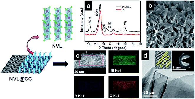
The typical XRD spectra of CC and the as-synthesized NVL@CC are shown in Fig. 1a. The XRD spectra confirm the peaks corresponding to (hkl) planes (003), (101), (012) and (113) of the as-synthesized NVL@CC. The peaks in NVL@CC are in good agreement with those in the referenced nickel vanadium carbonate hydroxide hydrate material with JCPDS card no. 052-1627. It can be argued that the presence of an intense high peak of carbon cloth at 25.6° overlapping with an intense peak of NVL@CC at 22.78°, due to the (006) plane and shifted slightly left in the XRD spectra, indicates the successful loading of NVL on carbon cloth. Also, there are no impurities detected in the as-synthesized NVL@CC. From the XRD spectra of the as-synthesized NVL@CC, the interlayer distance (d003) for the (003) plane calculated from Bragg's formula is found to be 0.79 nm.31,32 The surface morphology of NVL@CC (Fig. 1b and S1†) confirms the presence of well-separated, vertically grown and uniformly aligned nanosheets with 3D nanostructures on the carbon cloth. As seen from the SEM images of NVL@CC, the formation of honeycomb-like structures via the in situ growth process provides enriched electrochemically active sites. This will induce fast redox reactions on the electrode surfaces, and the interconnected porous channel can influence or help intercalation/deintercalation of ions in the electrolyte.33 Therefore, excellent electrochemical activity of the electrodes could be achieved. Elemental mapping in Fig. 1c shows the uniform distribution of Ni, V, and O in the NVL@CC. Fig. 1d presents the TEM and HRTEM images and SAED pattern for NVL@CC. TEM confirmed the formation of thin nanosheets (∼1–2 nm) of NVL. The SAED pattern reveals the semi-crystalline nature of the as-synthesized NVL.23 The HRTEM image of NVL@CC reveals that the crystal lattice fringe d-spacing was 0.26 nm, corresponding to the (101) plane of NVL. This result is consistent with the XRD spectra of NVL@CC. Fig. 2 presents the XPS spectra for the as-synthesized NVL@CC. The survey scan (Fig. 2a) showed the presence of both elements Ni and V in NVL@CC. Ni 2p spectra showed two main peaks, Ni 2p3/2 (850–870 eV) and Ni 2p1/2 (870–890 eV), resulting from the spin–orbital splitting of the p orbital. Ni 2p3/2 and Ni 2p1/2 present two main peaks at 853.9 eV and 871.7 eV along with two intense satellite peaks at 859.9 eV and 877.9 eV (Fig. 2b); this is the characteristic signature of Ni2+.34,35 V 2p core level spectra (Fig. 2c) showed three peaks for V3+ (516.2 eV), V4+ (516.9 eV) and V5+ (517.9 eV).36,37Fig. 2d shows the FTIR spectra for etched carbon cloth and NVL@CC. The FTIR spectra for CC and NVL@CC matched with each other, and a few new peaks appeared in NVL@CC due to the formation of NVL over CC. The absorption bands appearing at ∼3437 cm−1, ∼1639 cm−1 and ∼1072 cm−1 are primarily due to the stretching and bending vibrations of the –OH group, indicating the presence of water molecules in the interlayers and metal (Ni2+ and V3+)–hydroxyl bond.38 The bands present at ∼1373 cm−1 and ∼2920 cm−1 indicate CO32− and CO32−–H2O stretching vibrations, respectively.39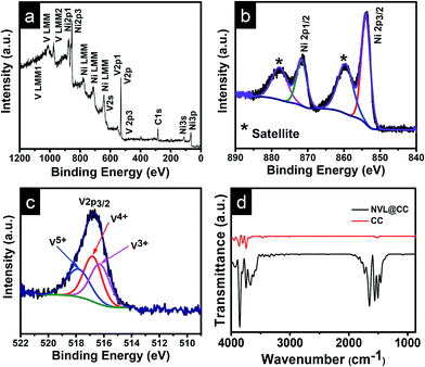 | ||
| Fig. 2 (a) XPS survey scan for various elements in NVL@CC; (b) Ni 2p core level spectra for NVL@CC; (c) V 2p core level spectra for NVL@CC; (d) FTIR spectra for etched CC and NVL@CC. | ||
Electrochemical characterization of NVL@CC was carried out through a three-electrode setup using 2 M KOH. Fig. 3a shows the CV curves for NVL@CC in the potential range of 0 to 0.5 V at scan rates varying from 5 mV s−1 to 100 mV s−1. The CV curves exhibited a well-resolved redox peak at all scan rates.40 It is expected that the redox peaks appearing in the CV curves are due to the redox behavior of Ni, present in NVL@CC.41 It is also evident from the CV curves that cathodic and anodic peaks shift toward more negative and more positive potential, respectively, as the scan rate increases from 5 mV s−1 to 100 mV s−1, suggesting the reversible faradaic behavior at the time of oxidation and reduction of NVL@CC. It is also clear from the CV curves that the redox current increases as we go from a low scan rate to a higher scan rate. The enhanced specific capacitance of the NVL@CC electrodes during CV is due to the reversible reactions of Ni2+ bound to OH−. V helps in increasing the conductivity, resulting in facile charge transportation for the NVL@CC.22,42 The same can be expressed by the following redox equation of the NVL@CC during the CV test.22,27
| Ni(OH)2 + OH− ↔ NiOOH + H2O + e− | (2) |
 | ||
| Fig. 3 (a) CV curves for NVL@CC at various scan rates; (b) GCD curves for NVL@CC at various current densities; (c) variation of specific capacity with current density. | ||
The GCD curves at various current densities (1 A g−1 to 10 A g−1) are shown in Fig. 3b. The shape of the GCD curves is nonlinear, indicating the quasi-reversible e− transfer between NVL@CC and electrolyte. It also confirms that NVL@CC behaves like a battery material and the corresponding specific capacitance is due to the faradaic mechanism.43 The GCD curves retained their shape as the current density was increased from 1 A g−1 to 10 A g−1, demonstrating the higher rate capability of NVL@CC. The specific capacity of NVL@CC was found to be 1226 C g−1 (2790 F g−1), 862 C g−1 (2000 F g−1), 663 C g−1 (1574 F g−1), 596 C g−1 (1445 F g−1), 550 C g−1 (1351 F g−1) and 430 C g−1 (1121 F g−1) at current densities of 1 A g−1, 2 A g−1, 3 A g−1, 4 A g−1, 5 A g−1 and 10 A g−1, respectively. The variation of specific capacity with current density is shown in Fig. 3c. This high rate capability of NVL@CC can be due to a reduction in the diffusion path of ions, increased accessible surface area and high electrical conductivity of carbon cloth.27 The specific capacitance for other materials grown on carbon cloth is compared in Table 1. NVL@CC showed the highest specific capacitance compared to other reported LDHs at a current density of 1 A g−1 while having a comparable working potential window. The GCD curves are used to calculate the potential drop due to internal resistances, found to be 11.28 mV at a current density of 1 A g−1 and increasing to 85.25 mV as the current density was increased to 10 A g−1. A small potential drop signifies the lower internal resistance of the electrode and confirms the higher conductivity of the NVL@CC material. The EIS spectrum for NVL@CC is presented in Fig. 4a and confirms that experimental data points are well harmonized with the fitted data points. The equivalent circuit fitting showed equivalent series resistance (Rs), charge transfer resistance (Rct) and pseudocapacitance (Cp) values of 2.38 Ω, 5.34 Ω and 4.55 mF, respectively. Lower charge transfer resistances are responsible for the faster redox kinetics during the charge and discharge process and higher conductivity of NVL@CC.44 The cycling stability curve for NVL@CC in Fig. 4b shows that the specific capacity value decreases continuously for the first 600 cycles and then starts increasing because of the creation of new active sites due to continuous charging and discharging.45 We did not observe any peeling of NVL from the surface of CC during the cycling and thus, depicting the good adhesion of NVL over the surface of CC. The cycling study showed 75% retention in specific capacity at a current density of 10 A g−1 after 2000 cycles. The capacitance decay may be due to a phase change, structural collapse or reduction of the active surface area during charging–discharging.46
| Active material | Specific capacitance at a lower current density (F g−1) | Specific capacitance at a higher current density (F g−1) | Electrolyte | Potential window | Ref. |
|---|---|---|---|---|---|
| Co–Fe LDH | 774 F g−1 at 1 A g−1 | 496 F g−1 at 10 A g−1 | 2 M KOH | −0.1–0.4 V | 27 |
| Co–Mn hydroxide | 633.4 F g−1 at 1 A g−1 | 477.8 F g−1 at 20 A g−1 | 1 M KOH | −0.1–0.4 V | 53 |
| Co–Mn LDH | 1079 F g−1 at 2.1 A g−1 | 891 F g−1 at 42 A g−1 | 1 M LiOH | −0.2–0.6 V | 54 |
| Ni–Mn LDH | 2239 F g−1 at 5 mA cm−2 | — | 2 M KOH | −0.1–0.5 V | 26 |
| CoNi0.5 LDH | 1938 F g−1 at 1 A g−1 | 1551 F g−1 at 50 A g−1 | 2 M KOH | 0–0.6 V | 55 |
| Ni–V LDH | 2790 F g−1 at 1 A g−1 | 1121 F g−1 at 10 A g−1 | 2 M KOH | 0–0.45 V | This work |
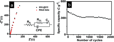 | ||
| Fig. 4 (a) EIS spectra for NVL@CC; (b) variation of specific capacity with the number of charge–discharge cycles at 10 A g−1. | ||
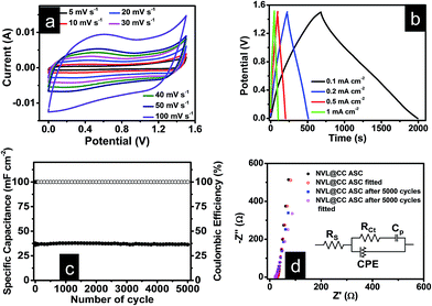
To further explore the potential of NVL@CC in flexible and lightweight wearable electronics, hybrid supercapacitor (HSC) devices were fabricated using PVA/LiCl as a gel polymer electrolyte. Fig. S2a† presents the CV curves of the NVL@CC//AC HSC at various potential windows which vary from 0.9 V to 1.5 V at a constant scan rate of 10 mV s−1. From this study, we can infer that the exact trace as obtained with the working window of 0 to 0.9 V for an NVL@CC HSC is followed further for all CV curves up to a 1.5 V potential window, suggesting that the potential window can be extended up to 1.5 V easily. Fig. 5a illustrates the typical CV curves for the NVL@CC//AC HSC in the potential window of 1.5 V at various scan rates. It is clear that the shape is not rectangular as shown for EDLCs, which is indicative of the intercalating pseudocapacitive nature of the NVL@CC electrode. It also indicates that as the scan rate is increased, the shape of the CV curve does not change much. Also, redox peaks shift towards more negative potentials, which is indicative of an increase in the capacitive process, agreeing well with the power law.47 To check the flexibility characteristics of the NVL@CC//AC HSC device, we tested the as-fabricated electrodes under various bending angles and in a twisted state. Fig. S2b† shows the CV curves for the NVL@CC//AC HSC device under normal conditions, at various bending angles (60°, 90°, 120°, and 180°) and in the twisted state. Fig. S2b† illustrates that there is no significant change in the device performance even after repeated bending and twisting of the NVL@CC//AC HSC. Fig. 6 shows the digital photographs of the NVL@CC//AC HSC at various bending angles and in the twisted state. The overall thickness of the device was ∼0.3 mm. These results illustrate that the NVL@CC//AC HSC device possesses very high flexibility and is lightweight, which is one of the most suitable criteria for wearable and portable electronics. Results for activated carbon coated on carbon cloth and etched carbon cloth are discussed in Fig. S3 and S4.† There is no significant contribution of etched carbon cloth in the device performance (Fig. S4c†). Fig. 5b and S2c† present the GCD curves for the NVL@CC//AC HSC device at various current densities varying from 0.1 mA cm−2 to 10 mA cm−2 in the potential window of 1.5 V. The GCD curves exhibit small non-linearity during charging and discharging, which illustrates the pseudocapacitive behavior of the NVL@CC//AC HSC. No significant iR-drop was recorded even at a higher current density of 10 mA cm−2, indicating the low internal resistance of the NVL@CC//AC HSC.48 The specific capacitance variation with charge density for three different devices is presented in Fig. 7a. The maximum specific capacitance was found to be 91 mF cm−2, 40 mF cm−2, 39 mF cm−2, and 38 mF cm−2 at current densities of 0.1 mA cm−2, 0.2 mA cm−2, 0.5 mA cm−2 and 1 mA cm−2, respectively. The maximum specific capacitance remained at 37 mF cm−2 even at a higher current density of 10 mA cm−2. The cycling stability of the NVL@CC//AC HSC device was tested at a current density of 5 mA cm−2. The devices showed no decay in specific capacitance and coulombic efficiency up to 5000 charge–discharge cycles, confirming the excellent cycle life of the NVL@CC//AC HSC device. In the literature, it was shown that LiCl/PVA gel electrolyte stabilized the cycling performance of V based compounds by preventing the loss of V during cycling.49Fig. 5d shows the EIS spectra of the NVL@CC//AC HSC device before and after 5000 charge–discharge cycles. It is observed from the EIS spectra that the quasi-vertical line in the lower frequency region makes a quite larger angle with the real axis as illustrated for a typical Warburg angle (45°), confirming a better electrolyte diffusion-controlled process at the electrode and electrolyte interface.47 The lower charge transfer resistance (Rct) of 16.6 Ω further indicates the higher conductivity of the NVL@CC//AC HSC. From the equivalent circuit, we can observe equivalent series resistance (Rs) and pseudocapacitance (Cp) values of 29.1 Ω and 12.7 mF, respectively. After 5000 cycles, Rct, Rs, and Cp values change to 20.6 Ω, 22.4 Ω and 16.1 mF, respectively. The energy density of the NVL@CC//AC HSC was found to be 0.69 mW h cm−3 at a power density of 2.5 mW cm−3 and it remained at 0.24 mW h cm−3 at a higher power density of 214.4 mW cm−3. Fig. 7b presents the Ragone plot for the NVL@CC//AC HSC device and other LDH materials. The Ragone plot shows that the energy density of the NVL@CC//AC device is higher than that of other reported flexible supercapacitors.50–52 The NVL@CC//AC HSC device was also used to light up a 1.8 V red light emitting diode (LED). Three such devices were used to power the LED for more than 1 min (Movie S1†).
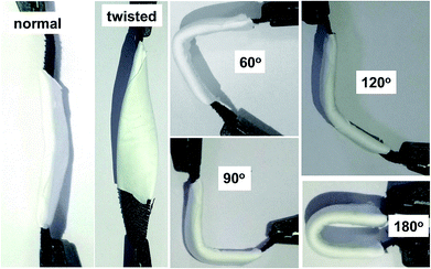 | ||
| Fig. 6 Digital photographs of the NVL@CC//AC HSC at a various bending angles and in the twisted state. | ||
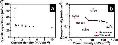 | ||
| Fig. 7 (a) Variation of specific capacitance with current density for the NVL@CC//AC HSC; (b) Ragone plot for the NVL@CC//AC HSC and other devices reported in the literature. | ||
Conclusion
In summary, NVL@CC has been synthesized through a facile and cost-effective hydrothermal route. The as-synthesized NVL@CC possesses a uniform, mechanically strong and highly ordered porous network with connected pores, which ensures high specific capacitance and enhanced cyclability. Furthermore, a full solid-state hybrid supercapacitor device was fabricated. The electrochemical performance of the solid-state flexible supercapacitors showed a negligible change upon bending and twisting of the devices. Hence, the procedure adopted for the synthesis of NVL@CC can be further applied to scalable applications and will help to develop future SC devices having high flexibility without compromising the cyclability and performance of the electrodes.Conflicts of interest
There are no conflicts to declare.Acknowledgements
RKG acknowledges financial assistance from the Department of Science and Technology (DST), India, through the INSPIRE Faculty Award (Project No. IFA-13 ENG-57) and Grant No. DST/TMD/CERI/C140(G).References
- J. Zhao, J. Chen, S. Xu, M. Shao, Q. Zhang, F. Wei, J. Ma, M. Wei, D. G. Evans and X. Duan, Adv. Funct. Mater., 2014, 24, 2938 CrossRef CAS.
- T. Purkait, G. Singh, D. Kumar, M. Singh and R. S. Dey, Sci. Rep., 2018, 8, 640 CrossRef PubMed.
- A. Tyagi, K. M. Tripathi and R. K. Gupta, J. Mater. Chem. A, 2015, 3, 22507 RSC.
- M. Zheng, L. Li, P. Gu, Z. Lin, W. Du, H. Xue and H. Pang, Energy Technol., 2017, 5, 544 CrossRef CAS.
- X. Guo, S. Zheng, G. Zhang, X. Xiao, X. Li, Y. Xu, H. Xue and H. Pang, Energy Storage Materials, 2017, 9, 150 CrossRef.
- H. Nishide and K. Oyaizu, Science, 2008, 319, 737 CrossRef CAS PubMed.
- A. Tyagi, N. Singh, Y. Sharma and R. K. Gupta, Catal. Today, 2019, 325, 33 CrossRef CAS.
- L. Chen, X. Guo, W. Lu, M. Chen, Q. Li, H. Xue and H. Pang, Coord. Chem. Rev., 2018, 368, 13 CrossRef CAS.
- Prateek, V. K. Thakur and R. K. Gupta, Chem. Rev., 2016, 116, 4260 CrossRef CAS PubMed.
- A. Eftekhari, J. Mater. Chem. A, 2018, 6, 2866 RSC.
- F. Wang, S. Sun, Y. Xu, T. Wang, R. Yu and H. Li, Sci. Rep., 2017, 7, 4707 CrossRef PubMed.
- W. Wang, W. Liu, Y. Zeng, Y. Han, M. Yu, X. Lu and Y. Tong, Adv. Mater., 2015, 27, 3572 CrossRef CAS PubMed.
- X. Li, J. Wei, Q. Li, S. Zheng, Y. Xu, P. Du, C. Chen, J. Zhao, H. Xue, Q. Xu and H. Pang, Adv. Funct. Mater., 2018, 28, 1800886 CrossRef.
- Z. Lu, W. Xu, W. Zhu, Q. Yang, X. Lei, J. Liu, Y. Li, X. Sun and X. Duan, Chem. Commun., 2014, 50, 6479 RSC.
- K. Fan, H. Chen, Y. Ji, H. Huang, P. M. Claesson, Q. Daniel, B. Philippe, H. Rensmo, F. Li, Y. Luo and L. Sun, Nat. Commun., 2016, 7, 11981 CrossRef CAS PubMed.
- G. Chen, Y. Zhao, G. Fu, P. N. Duchesne, L. Gu, Y. Zheng, X. Weng, M. Chen, P. Zhang, C.-W. Pao, J.-F. Lee and N. Zheng, Science, 2014, 344, 495 CrossRef CAS PubMed.
- X. Long, J. Li, S. Xiao, K. Yan, Z. Wang, H. Chen and S. Yang, Angew. Chem., Int. Ed., 2014, 53, 7584 CrossRef CAS PubMed.
- M. Nakayama, K. Komine and D. Inohara, ECS Trans., 2017, 75, 31 CrossRef.
- H. Xinping, G. Bo, W. Guibao, W. Jiatong and Z. Chun, Electrochim. Acta, 2013, 111, 210 CrossRef.
- G. Wang, H. Wang, X. Lu, Y. Ling, M. Yu, T. Zhai, Y. Tong and Y. Li, Adv. Mater., 2014, 26, 2676 CrossRef CAS PubMed.
- M. Shao, R. Zhang, Z. Li, M. Wei, D. G. Evans and X. Duan, Chem. Commun., 2015, 51, 15880 RSC.
- H. W. Park, J. S. Chae, S.-M. Park, K.-B. Kim and K. C. Roh, Met. Mater. Int., 2013, 19, 887 CrossRef CAS.
- R. Li, Z. Hu, X. Shao, P. Cheng, S. Li, W. Yu, W. Lin and D. Yuan, Sci. Rep., 2016, 6, 18737 CrossRef CAS PubMed.
- A. Tyagi, M. C. Joshi, A. Shah, V. K. Thakur and R. K. Gupta, ACS Omega, 2019, 4, 3257 CrossRef CAS.
- Q. Cheng, J. Tang, J. Ma, H. Zhang, N. Shinya and L.-C. Qin, J. Phys. Chem. C, 2011, 115, 23584 CrossRef CAS.
- L. Shi, P. Sun, L. Du, R. Xu, H. He, S. Tan, C. Zhao, L. Huang and W. Mai, Mater. Lett., 2016, 175, 275 CrossRef CAS.
- K. Ma, J. P. Cheng, F. Liu and X. Zhang, J. Alloys Compd., 2016, 679, 277 CrossRef CAS.
- M. Shao, Z. Li, R. Zhang, F. Ning, M. Wei, G. Evans David and X. Duan, Small, 2015, 11, 3530 CrossRef CAS PubMed.
- P. Howli, S. Das, S. Sarkar, M. Samanta, K. Panigrahi, N. S. Das and K. K. Chattopadhyay, ACS Omega, 2017, 2, 4216 CrossRef CAS.
- H. Zhang, D. Xiao, Q. Li, Y. Ma, S. Yuan, L. Xie, C. Chen and C. Lu, J. Energy Chem., 2018, 27, 195 CrossRef.
- L. Zhang, X. Zhang, L. Shen, B. Gao, L. Hao, X. Lu, F. Zhang, B. Ding and C. Yuan, J. Power Sources, 2012, 199, 395 CrossRef CAS.
- Y. Tao, L. Ruiyi, Y. Tingting and L. Zaijun, Electrochim. Acta, 2015, 152, 530 CrossRef CAS.
- J. Zhu and J. He, ACS Appl. Mater. Interfaces, 2012, 4, 1770 CrossRef CAS PubMed.
- A. N. Mansour, Surf. Sci. Spectra, 1994, 3, 231 CrossRef CAS.
- M. C. Biesinger, B. P. Payne, A. P. Grosvenor, L. W. M. Lau, A. R. Gerson and R. S. C. Smart, Appl. Surf. Sci., 2011, 257, 2717 CrossRef CAS.
- M. C. Biesinger, L. W. M. Lau, A. R. Gerson and R. S. C. Smart, Appl. Surf. Sci., 2010, 257, 887 CrossRef CAS.
- G. Silversmit, D. Depla, H. Poelman, G. B. Marin and R. De Gryse, J. Electron Spectrosc. Relat. Phenom., 2004, 135, 167 CrossRef CAS.
- X. Li, Y. Zhang, W. Xing, L. Li, Q. Xue and Z. Yan, J. Power Sources, 2016, 331, 67 CrossRef CAS.
- F. Zhang, C. Zhang, R. Zeng, L. Song, L. Guo and X. Huang, Metals, 2016, 6, 85 CrossRef.
- J. Bhagwan, V. Sivasankaran, K. L. Yadav and Y. Sharma, J. Power Sources, 2016, 327, 29 CrossRef CAS.
- G. A. Caravaggio, C. Detellier and Z. Wronski, J. Mater. Chem., 2001, 11, 912 RSC.
- S. Wu, K. S. Hui and K. N. Hui, J. Phys. Chem. C, 2015, 119, 23358 CrossRef CAS.
- Z.-A. Hu, Y.-L. Xie, Y.-X. Wang, H.-Y. Wu, Y.-Y. Yang and Z.-Y. Zhang, Electrochim. Acta, 2009, 54, 2737 CrossRef CAS.
- P. F. Teh, Y. Sharma, S. S. Pramana and M. Srinivasan, J. Mater. Chem., 2011, 21, 14999 RSC.
- K. Tang, Y. Li, H. Cao, C. Su, Z. Zhang and Y. Zhang, Electrochim. Acta, 2016, 190, 678 CrossRef CAS.
- M. Li, J. P. Cheng, J. Wang, F. Liu and X. B. Zhang, Electrochim. Acta, 2016, 206, 108 CrossRef CAS.
- M. S. Javed, X. Han, C. Hu, M. Zhou, Z. Huang, X. Tang and X. Gu, ACS Appl. Mater. Interfaces, 2016, 8, 24621 CrossRef CAS PubMed.
- J. Yu, J. Wu, H. Wang, A. Zhou, C. Huang, H. Bai and L. Li, ACS Appl. Mater. Interfaces, 2016, 8, 4724 CrossRef CAS PubMed.
- G. Wang, X. Lu, Y. Ling, T. Zhai, H. Wang, Y. Tong and Y. Li, ACS Nano, 2012, 6, 10296 CrossRef CAS PubMed.
- N. Yu, M.-Q. Zhu and D. Chen, J. Mater. Chem. A, 2015, 3, 7910 RSC.
- H.-Y. Li, Y. Yu, L. Liu, L. Liu and Y. Wu, Electrochim. Acta, 2017, 228, 553 CrossRef CAS.
- A. Ramadoss, K.-N. Kang, H.-J. Ahn, S.-I. Kim, S.-T. Ryu and J.-H. Jang, J. Mater. Chem. A, 2016, 4, 4718 RSC.
- D. Wang, J. Li, D. Zhang, T. Liu, N. Zhang, L. Chen, X. Liu, R. Ma and G. Qiu, J. Mater. Sci., 2016, 51, 3784 CrossRef CAS.
- J. Zhao, J. Chen, S. Xu, M. Shao, D. Yan, M. Wei, D. G. Evans and X. Duan, J. Mater. Chem. A, 2013, 1, 8836 RSC.
- M. F. Warsi, I. Shakir, M. Shahid, M. Sarfraz, M. Nadeem and Z. A. Gilani, Electrochim. Acta, 2014, 135, 513 CrossRef CAS.
Footnote |
| † Electronic supplementary information (ESI) available: Low magnification FESEM and FTIR for NVL@CC and electrochemical characterization of activated carbon coated carbon cloth. See DOI: 10.1039/c9na00152b |
| This journal is © The Royal Society of Chemistry 2019 |


