 Open Access Article
Ultrasonochemically-induced MnCo2O4 nanospheres synergized with graphene sheet as a non-precious bi-functional cathode catalyst for rechargeable zinc–air battery†
Shivaraju Guddehalli
Chandrappa
ab,
Prabu
Moni
 ab,
Guruprakash
Karkera
ab and
Annigere S.
Prakash
 *ab
*ab
aCSIR, Central Electrochemical Research Institute-Chennai Unit, CSIR Madras Complex, Taramani, Chennai-600113, India. E-mail: prakash.as@gmail.com; prakash@cecri.res.in
bAcademy of Scientific and Innovative Research (AcSIR), Ghaziabad-201002, India
First published on 15th May 2019
Abstract
Rechargeable zinc–air batteries are considered to be more sustainable and efficient candidates for safe, low-cost energy storage because of their higher energy density and the abundance of zinc resources. Recently Zn–air batteries have aroused significant research attention, however, because an unresolved impediment due to the notorious instability of the oxygen evolution reaction (OER) and oxygen reduction reaction (ORR) kinetics of the cathode catalyst limit their practical application. Herein, we report the synthesis of non-precious MnCo2O4 nanospheres synergized with a graphene sheet as a bi-functional cathode catalyst for rechargeable Zn–air battery application using a one-pot probe sonochemical method. Structural characterization confirms that the MnCo2O4 nanospheres successfully anchored on graphene sheet. X-ray photoelectron spectroscopy revealed that the Mn and Co in the MnCo2O4 are in mixed valence states on the graphene sheet surface and the MnCo2O4–graphene sheet (MCO–GS) hybrid catalyst exhibits excellent OER and ORR activity compared with their individual counterparts. A rechargeable Zn–air battery using an MCO–GS catalyst reveals unique small charge–discharge overpotential, cycling stability and higher rate capability than a bare MnCo2O4 (MCO) catalyst. This superiority in electrocatalytic activity combined with simplicity of material synthesis, turn the MCO–GS hybrid into a promising catalyst for a rechargeable Zn–air battery.
1. Introduction
Due to energy crises and limited fossil fuel in the Earth's reserves it is necessary to develop clean and more sustainable electrochemical energy storage technologies. In this context, rechargeable metal–air (M = Li, Zn, Al, etc.) batteries are believed to be one way to obtain a more sustainable and efficient storage device due to their higher theoretical energy densities than state-of-the-art lithium-ion batteries.1 Among various metal–air batteries, lithium–air batteries have become the most lauded for the next generation of batteries because of their higher theoretical specific energy (5928 W h L−1) and higher nominal cell voltage (2.96 V).2,3 Yet, the commercialization of the Li–air battery is still a debacle due to the unstable nature of Li metal when exposed to air and aqueous electrolytes.4 Notwithstanding this, zinc–air batteries have been revisited as possible candidates for commercialization, due to their higher specific energy (1218 W h kg−1), volumetric energy density (6136 W h L−1), cell voltage (1.66 V), safe and deep discharge plateau, nontoxicity and the abundant nature of zinc resources.1,4 Despite their versatility, the commercialization of Zn–air batteries has been greatly hampered by the slow kinetics associated with the oxygen reduction reaction (ORR) and the oxygen evolution reaction (OER), which are two vital reactions at the cathode side during the discharge and charge reactions of a Zn–air battery.5 In the past few years, the development of highly active and stable bi-functional catalysts for both ORR and OER characteristics have attracted extensive research studies.6–8 Pt/C and RuO2/IrO2 are conceived to be the best ORR and OER catalysts, respectively, but their scarcity and high cost limit their practical application.9,10 Therefore, it is imperative to find a more abundant, highly efficient and inexpensive bi-functional catalyst for Zn–air battery applications. Recently, carbonaceous based materials (carbon nanotubes, graphene, graphene oxide) and heteroatoms (N, P, or S) doped-carbon materials have attracted interest as ORR catalysts due to their intrinsic advantages, such as higher electrochemical conductivity, higher surface area, and electrochemical stability. On the other hand, the oxides of Mn, Fe, Co and Ni belonging to the family of spinels and perovskites (ABxB′1−xO3) are promising OER catalysts.11 Over the years, graphene sheet anchored 3d transition metal based electrocatalysts, such as Co3O4, MnCo2O4, NiCo2O4, or CoMn2O4 and perovskites such as LaCoO3 or LaNiO3 have been widely employed in the field of electrocatalytic activities as well as in Zn–air batteries.12,13 This composite structure can stabilize the metal oxide catalysts and significantly affect their electrocatalytic activities and stability via a synergistic effect.14 In particular, within the MnCo2O4 composite structure, the mixed valence state of cobalt (Co2+ and Co3+) could improve the ORR and OER activity,15 where incorporating manganese (Mn3+ and Mn4+) valence states into spinel Co3O4 could increase the surface area of the catalyst, resulting in an improvement in electrocatalytic activities.16 Duan et al.14 designed MnCo2O4/macroporous carbon nanofiber composite arrays as bi-functional oxygen catalysts for rechargeable Zn–air batteries. Adnan et al.17 presented a reduced graphene oxide decorated with MnCo2O4 as a multifunctional material for mechanically rechargeable and hybrid Zn–air batteries. Moni et al.18 have shown the electrocatalytic activities of graphene-supported CoMn2O4 as a bi-functional catalyst for a rechargeable Zn–air battery application. Hui et al.19 studied the highly efficient catalytic activities of a CoMn2O4/N-CNTs cathode for a flexible Zn–air battery application. We have recently reported an MnCo2O4–graphene hybrid material as the cathode catalyst for Li–O2 batteries20 and Yongye et al.21 designed an MnCo2O4/N-doped graphene hybrid material for an oxygen reduction reaction catalyst in alkaline conditions. These results show that binary metal oxide/carbon composites exhibited excellent bi-functional catalytic activities for rechargeable Zn–air battery applications. The electrochemical activities and morphology of the prepared nanomaterial altered with their method of preparation. Within a large variety of synthesis routes, a sonochemical method is an efficient route to synthesize various inorganic nanomaterials.22 Sonochemistry induces chemical changes due to acoustic cavitation (the formation, growth, and implosive collapse of bubbles), which produces temperatures above 5000 K, pressures exceeding 1000 atmospheres and heating and cooling rates in excess of 1010 K s−1.23 These transient conditions can play a synergistic role in the synthesis of nanomaterials.24 Through this study, we present MnCo2O4 nanospheres anchored on a graphene sheet as a bi-functional cathode catalyst for a rechargeable Zn–air battery application. This composite material was synthesized via a one-pot probe sonochemical method using metal salts (Co, Mn) and a graphene sheet in an aqueous medium, as reported in our previous publication.20 This method is a very simple, cost-effective and highly efficient approach for the synthesis of nanocomposite material without causing external heating. We further investigated the catalytic activities for a rechargeable Zn–air battery application by consuming oxygen from the atmosphere as a reactant.2. Experimental
2.1 Material synthesis
2.2 Material characterization
Powder X-ray diffraction of the synthesized material was recorded using a BRUKER D8 Advance Da Vinci diffractometer using CuKα (λ = 1.5418 Å) radiation. Scanning electron microscopy images were studied using a Carl Zeiss 130 VP FESEM. XPS was performed using a Thermo Fischer Scientific Multilab 2000 spectrometer using non-monochromatic AlKα radiation (1486.6 eV) as an X-ray source operated at 150 W (12 kV, 12.5 mA). Transmission electron microscopy studies were carried out using a Technai-20 G2 microscope. Brunauer–Emmett–Teller (BET) surface areas were recorded by a Micromeritics ASAP 2020 instrument and pore sizes were estimated from the pore-size distribution curves obtained from the adsorption isotherms using the Barrett–Joyner–Halenda method.2.3 Electrochemical activity tests
The bi-functional activity (ORR–OER) of MCO–GS and a bare MCO cathode catalyst were carried out in an electrochemical workstation (Biologic, VSP/VMP 3B-20, France) at room temperature with a three electrode system by using CV and LSV techniques. The catalyst ink was made by dispersing 3.55 mg of catalyst in a solution containing 10 µL of Nafion ionomer, 250 µL of ethanol and 150 µL of mQ water mixture by ultra-sonication for 30 min. 4 µL of catalyst ink was coated on glassy carbon as the working electrode, a Pt wire was used as the counter electrode and Ag/AgCl as the reference electrode. The electrochemical characterizations were carried out in N2/O2 saturated alkaline aqueous 0.1 M KOH electrolyte.2.4 Zinc–air battery fabrication and testing
The zinc–air battery performance of the MCO–GS and bare MCO based cathode catalyst was carried out in a homemade Swagelok setup with an electrochemical workstation (Biologic, VSP/VMP 3B-20, France) at room temperature using galvanostatic and galvanodynamic techniques. The polished zinc metal sheet, 6 M KOH solution, polypropylene membrane and catalyst-coated gas diffusion layer (GDL) were used as anode, electrolyte, separator and cathode, respectively. The cathode catalyst slurry was prepared using 1 mg of MCO–GS or bare MCO catalyst mixed ultrasonically with 3 mL of ethanol, 1 mL of mQ water and 0.11 mg of 5 wt% Nafion ionomer solution. Then the homogenously dispersed slurry was coated on a GDL (SGL Carbon – GDL 38 BC with active area 1 cm2) using an airbrush technique to obtain a catalyst loading of 1 mg cm−2. The zinc–air battery was constructed by sandwiching anode, electrolyte-soaked separator and air-cathode in the Swagelok setup. The zinc–air battery was operated by consuming open air at ambient pressure and temperature. The specific capacity of the zinc–air battery was calculated based on the mass of Zn metal used, while the current density applied was calculated based on the active mass of the catalyst used. The electrochemical impedance spectra of the zinc–air battery were conducted within the frequency range 400 kHz to 1 mHz with a perturbation voltage of 10 mV vs. Zn/Zn2+. For a post-mortem analysis, the cells were disassembled and the cycled electrodes were regained and further subjected to XRD, FE-SEM and XPS analysis.3. Results and discussion
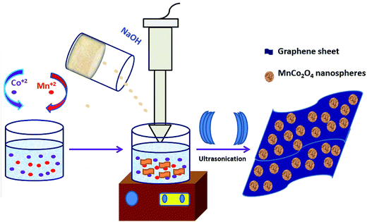
A single-step sonochemical route was used to synthesize MCO–GS and bare MCO catalysts. In the sonochemical reaction Co(OAc)2 and Mn(OAc)2 in a 2![[thin space (1/6-em)]](https://www.rsc.org/images/entities/char_2009.gif) :
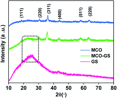
:![[thin space (1/6-em)]](https://www.rsc.org/images/entities/char_2009.gif) 1 ratio were reacted with graphene suspension in an ultrasonication probe treatment. Subsequently, the NaOH solution was added dropwise until the solution turned into a blue-colored precipitate (see Experimental section for details). This step was referred to as the hydroxide formation phase (Fig. S1†), during which NaOH was added to mediate the nucleation of metal species onto the metal hydroxide phase on the graphene surface. The sonication continued for the next 1 h to change the color from blue to blackish brown, indicating the conversion of the hydroxide phase into a complex oxide to form the MCO–GS hybrid. The structures of bare MCO and MCO–GS synthesized by a one-pot sonochemical route were confirmed by powder X-ray diffraction. The powder X-ray diffraction patterns collected from the pristine and graphene nanocomposites along with bare graphene are shown in Fig. 1. The obtained diffraction pattern corresponding to the graphene sheet (GS) shows a broad peak around 20–30°. The prominent phase peaks observed at 2θ = 30.1°, 35.7°, 43.5°, 57.9° and 63.6° for MCO and MCO–GS could be indexed to (220), (311), (400), (511) and (440) planes, respectively, corresponding to a cubic phase with Fd
1 ratio were reacted with graphene suspension in an ultrasonication probe treatment. Subsequently, the NaOH solution was added dropwise until the solution turned into a blue-colored precipitate (see Experimental section for details). This step was referred to as the hydroxide formation phase (Fig. S1†), during which NaOH was added to mediate the nucleation of metal species onto the metal hydroxide phase on the graphene surface. The sonication continued for the next 1 h to change the color from blue to blackish brown, indicating the conversion of the hydroxide phase into a complex oxide to form the MCO–GS hybrid. The structures of bare MCO and MCO–GS synthesized by a one-pot sonochemical route were confirmed by powder X-ray diffraction. The powder X-ray diffraction patterns collected from the pristine and graphene nanocomposites along with bare graphene are shown in Fig. 1. The obtained diffraction pattern corresponding to the graphene sheet (GS) shows a broad peak around 20–30°. The prominent phase peaks observed at 2θ = 30.1°, 35.7°, 43.5°, 57.9° and 63.6° for MCO and MCO–GS could be indexed to (220), (311), (400), (511) and (440) planes, respectively, corresponding to a cubic phase with Fd![[3 with combining macron]](https://www.rsc.org/images/entities/char_0033_0304.gif) space group (JCPDS No-00-001-1130). For the MCO–GS pattern, a slight additional amorphous peak appearing at 2θ = 20–30° corresponds to the graphene sheet, which further confirms that the MCO particles are homogeneously distributed on the graphene sheet.20
space group (JCPDS No-00-001-1130). For the MCO–GS pattern, a slight additional amorphous peak appearing at 2θ = 20–30° corresponds to the graphene sheet, which further confirms that the MCO particles are homogeneously distributed on the graphene sheet.20
The morphologies of bare MCO and MCO–GS nanocomposites were examined using field emission scanning electron microscopy (FESEM) and high-resolution transmission electron microscopy (TEM/HRTEM). The FESEM images of bare MCO (Fig. 2a) composed of nanospheres with sizes in the range 50–60 nm, and careful observation revealed that these nanospheres constitute the mesoporous structure.
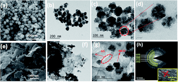 | ||
| Fig. 2 (a–d) FESEM, TEM images of bare MCO, (e–g) FESEM, TEM images and (h) SEAD pattern of MCO–GS catalyst (inset (h) HRTEM image of MCO–GS catalyst). | ||
Micrographs of the MCO–GS nanocomposites (Fig. 2e) show that the MCO nanospheres of 50–60 nm are uniformly dispersed all over the graphene sheets without detachment or aggregation.20 The TEM micrographs of MCO and the MCO–GS nanocomposites are shown in Fig. 2. The images corresponding to MnCo2O4 pristine samples are shown in Fig. 2b–d and images from MCO–GS are shown in Fig. 2f and g. The MCO nanospheres are homogeneously distributed on the graphene sheet (Fig. 2g). The SAED pattern from the MCO–GS nanocomposite (Fig. 2h) area shows ring spots which confirm the well-isolated single crystalline structure, and the HRTEM image of MCO–GS shows that the obtained lattice spacings are around 0.25 nm, which matches the (311) plane (inset Fig. 2h). The N2 adsorption–desorption isotherm of the MCO–GS composite shows a Type-IV hysteresis loop with average pore size 5 nm, which further confirms that the nanospheres constitute the mesoporous structure (Fig. S2†).
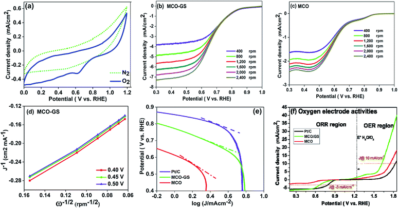
To investigate the kinetics and mechanism of the OER/ORR reaction, cyclic voltammetry (CV) and rotating disc electrode (RDE) experiments were carried out. Fig. 3a shows the CV curves of the MCO–GS catalyst in O2- and N2-saturated 0.1 M KOH solution. In O2-saturated KOH solution, the MCO–GS hybrid shows a sharp ORR onset potential of 0.85 V versus the reversible hydrogen electrode (RHE) suggesting that the MCO–GS catalyst enhances the ORR activity. In order to study the kinetic behaviour of the prepared catalysts, linear sweep voltammogram (LSV) experiments were recorded at different rotation speeds (Fig. 3b and c). The current density of the MCO–GS hybrid catalyst increased with increasing rotation from 400 to 2400 rpm by facilitating the greater convectional mass transfer of oxygen molecules from the bulk electrolyte to the electrode surface.
The half wave potentials of the MCO–GS hybrid (0.68 V vs. RHE) show more positive potential than the bare MCO catalyst (0.58 V vs. RHE) at 1600 rpm, and also the Koutecky–Levich (K–L) plot of MCO–GS shows good linearity and parallelism (Fig. 3d), which suggests first-order kinetics with respect to dissolved oxygen concentration.25,26 The slope obtained from the K–L plot confirms that mixed 2- and 4-electron pathway in the overall ORR reaction. Fig. 3e shows the Tafel plot of the prepared catalysts. MCO–GS exhibits a Tafel slope of 97 mV per decade, which is close to the value of state-of-the-art Pt/C of 73 mV per decade and much better than MCO, suggesting that the MCO–GS catalyst shows superior activity to the MCO catalyst. To evaluate the oxygen evolution reaction (OER) activities (Fig. S3a†) of MCO–GS, MCO and commercial Pt/C catalysts, LSV experiments were carried out at 1600 rpm RDE. MCO–GS shows a substantially lower overpotential at 1.61 V, reaching a current density of 10 mA cm−2, whereas, MCO and Pt/C show large overpotentials of 1.75 and 1.82 V, respectively. The MCO–GS hybrid shows a smaller OER overpotential than previously reported Mn and Co binary metal oxide based catalysts.27,28Fig. 3f shows the oxygen electrode activity of MCO–GS, and MCO and Pt/C catalysts calculated using a solar to fuel device conversion scale benchmark of ΔE1/2 = (OER at 10 mA cm−2 − ORR at 3 mA cm−2). The bi-functional activities were found to be 0.76 V and 1.04 V for MCO–GS and Pt/C catalysts, respectively. MCO–GS shows better bi-functional activity than MCO and Pt/C catalysts; this is due to the higher synergetic interaction between MCO nanospheres and the graphene sheet in the case of the MCO–GS catalyst.
From the above electrochemical investigations, the MCO–GS hybrid showed a moderate bi-functional activity, in comparison to benchmark catalysts such as IrO2/Pt/C.
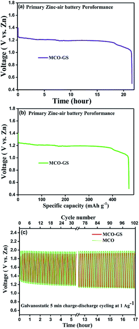
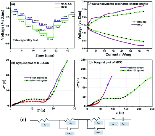
Therefore, we further evaluated the MCO–GS as a cathode catalyst for a zinc–air battery application. As illustrated in Fig. 4a, the open-circuit voltage (OCV) of a primary Zn–air battery assembled using an MCO–GS catalyst shows 1.45 V and it starts discharging from the average working voltage plateau of 1.25 V at a current density of 1 Ag−1. The voltage vs. specific capacity plot shown in Fig. 4b displays a discharge capacity of 490 mA h g−1 and is discharged over 20 h. Fig. 4c shows typical galvanostatic charge–discharge curves for the secondary zinc–air battery, the initial charge and discharge voltage of an MCO–GS catalyst with a smaller voltage gap of 0.60 V, which is slightly increased to 0.79 V after 100 cycles with a round-trip efficiency of 59%. This result shows that MCO–GS exhibits a lower voltage gap with an exceptional cycling performance over 100 cycles and a higher round-trip efficiency compared to the bare MCO catalyst. Further, a rate capability test was carried out for both hybrid and bare catalysts at different current rates (Fig. 5a). The hybrid catalyst shows excellent rate performance compared to the bare catalyst. Even when the hybrid catalyst was tested under a high current rate (25 mA) it again showed a similar discharge performance under similar discharge conditions (1 mA). Fig. 5b shows the galvanodynamic charge–discharge studies of MCO–GS and bare catalysts at different current densities. As predicted, the MCO–GS catalyst shows smaller charge–discharge polarization voltages compared to the pristine catalyst. These results further confirm that not only under galvanostatic conditions, but also under galvanodynamic conditions, the MCO–GS catalyst outperforms the bare catalyst in a Zn–air battery application, due to the interactive effect within the MCO nanoparticles and graphene sheets.
Further, to get details about the electrode kinetics and conductivity of the catalysts, electrochemical impedance spectroscopy (EIS) was employed. Nyquist plots of both electrodes before and after completing 100 cycles are given in Fig. 5c and d. The EIS spectra consist of two regions: one in the semicircle region in the higher frequency range represents electrolyte resistance (Rs), solid–electrolyte interface (Rint) and charge transfer (Rct) and the other one in the sloping region in a lower frequency region represents the Warburg resistance (W). The equivalent circuit model obtained from the fitted EIS data is shown in Fig. 5e. In the equivalent circuit, Rs is the electrolyte resistance, Rint is the resistance of the SEI, Rct is the charge transfer resistance, W is the Warburg resistance, Cdl represents double layer capacitance and CPE1 and CPE2 indicate the interface and double layer constant phase elements, respectively. The simulated Rs, Rint and Rct values from the EIS data are depicted in Table 1. The electrolyte resistance (Rs) is negligible in the case of both catalysts. Before cycling, the Rct value of the MCO–GS electrode was 11 Ω and it remained almost the same even after 100 cycles. Whereas the bare electrode charge transfer resistance (Rct) value of 14 Ω increases dramatically to 118 Ω after cycling. The charge transfer resistance Rct is interrelated with the kinetics of the electrocatalysts, a lower value corresponding to a faster reaction rate.28 The MCO–GS composite displays better catalytic activity, which could be enhanced by the graphene sheet anchored on the catalyst, which improves the capability of electrolyzing both OER and ORR via a synergistic effect and offers greater stability.
| Sample | R s/ohm | R int/ohm | R ct/ohm | |
|---|---|---|---|---|
| MCO | Fresh electrode | 0.92 | 4.35 | 14.14 |
| After 100 cycle | 0.67 | 8.93 | 118.8 | |
| MCO–GS | Fresh electrode | 0.83 | 3.75 | 11.4 |
| After 100 cycle | 0.39 | 1.95 | 15.05 | |
Hence, the MCO–GS catalyst is a potentially favourable bi-functional catalyst for Zn–air battery applications. In order to understand the structural, morphological and surface oxidation chemistry of the cycled cathode catalyst, pristine and a 100 cycled electrode were subjected to ex situ studies, such as XRD, FESEM and XPS. The XRD patterns of pristine and cycled MCO–GS electrodes are shown in Fig. 6a. The obtained diffraction patterns of both the pristine and the cycled electrode show a MnCo2O4 tetragonal phase, but in the case of the cycled electrode, some additional peaks were observed corresponding to ZnO and K2CO3 impurities formed during the course of charging–discharging. The precipitation of ZnO occurs only at the anode surface, while in this study a polymeric polypropylene membrane with 75% open porosity was used as a separator, which allows the easy infiltration of soluble zincate ions from the anode, which were further precipitated at the cathode side. Fig. 6b–e show FESEM images of the pristine and cycled electrodes. The pristine electrode shows MCO nanospheres uniformly anchored on the graphene sheets (Fig. 6b and c). The 100 cycled electrode (Fig. 6d, e and S4†) exhibits a similar morphology to the pristine electrode and additionally shows some thin coating over the surface, possibly due to the formation of minor ZnO and carbonates.28 The catalysts were further investigated by XPS. Fig. 7a and b shows the survey spectra of pristine and cycled MCO–GS electrodes. The pristine electrode displays the presence of Co 2p, Mn 2p, O 1s and C 1s, and the cycled electrode shows Zn 2p, Co 2p, Mn 2p, O 1s and C 1s. The Co 2p spectrum splits into two spin–orbit doublets and two satellite peaks. The first doublets are at 781.18 eV (Co 2p3/2) and 796.52 eV (Co 2p1/2) and the second doublets are at 780.07 eV (Co 2p3/2) and 795.12 eV (Co 2p1/2), which could be ascribed to Co3+ and Co2+, respectively. The Mn 2p spectrum is broad and the spectrum is deconvoluted into a set of two peaks observed at 643.69 eV and 642.17 eV, and at 653.75 eV and 654.06 eV of Mn 2p3/2 and Mn 2p1/2, respectively, indicating the presence of Mn3+ and Mn2+. These results suggest that Mn and Co in MnCo2O4 are in mixed valence states. The XPS analysis further confirms that the surface oxidation states of pristine catalyst and cycled catalyst remain unchanged (Fig. 7c and d). Hence, there are no structural and morphological changes occurring at the cathode side. However, there are structural and morphological changes occurring at the anode side by means of precipitation and re-deposition of ZnO on the anode side which need to be diminished by adopting suitable anode morphologies for long-term cycling.
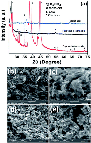 | ||
| Fig. 6 Ex situ analysis of the MCO–GS cathode: (a) XRD pattern of pristine and cycled electrodes, (b and c) FESEM images of pristine electrode and (d and e) cycled electrode. | ||
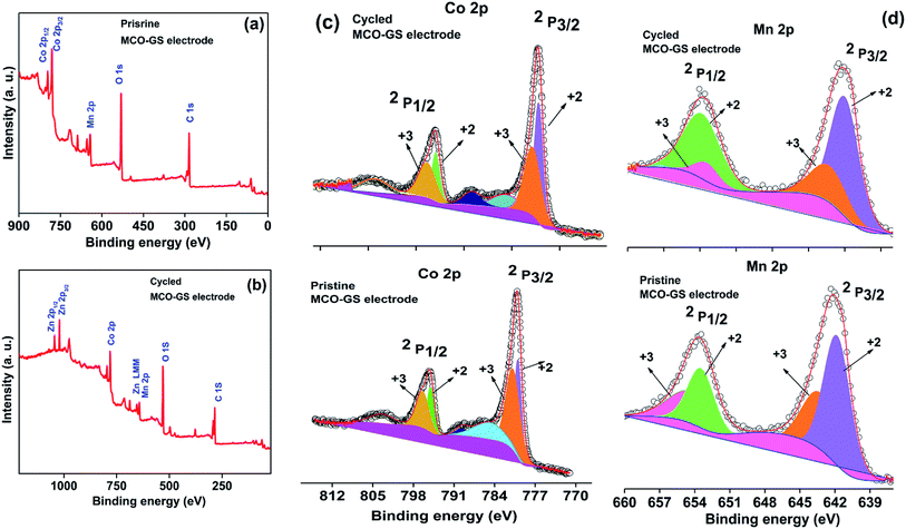 | ||
| Fig. 7 Ex situ XPS spectra of MCO–GS cathode: (a) survey scan of pristine electrode, (b) survey scan of cycled electrode, (c) Co 2p region and (d) Mn 2p region. | ||
4. Conclusions
In summary, we have synthesized non-precious MnCo2O4 nanospheres anchored on a graphene sheet via a one-pot sonochemical method. Through a combination of FE-SEM and TEM studies, we find that the MnCo2O4 nanospheres are uniformly distributed on the graphene sheet. The prepared MCO–GS hybrid exhibits superior bi-functional catalysis for ORR/OER activities compared with a bare MCO catalyst. In addition, the catalysts were demonstrated as a Zn–air battery cathode. MCO–GS hybrid exhibits good capacity retention and a good rate performance with a low charging–discharging overpotential. This superior bi-functional ORR/OER activity, as well as the rechargeable Zn-battery application of the MCO–GS hybrid catalyst, was attributed to (i) higher synergetic interaction between MnCo2O4 nanospheres and the graphene sheet and (ii) faster charge transfer facilitated by the graphene sheet. Due to their simple method of synthesis, low cost and high catalytic activity, the MCO–GS hybrid acts as an alternative to precious metal-based catalysts towards rechargeable Zn–air battery applications.Conflicts of interest
There are no conflicts to declare.Acknowledgements
Shivaraju G. C. greatly acknowledges CSIR-UGC for granting Fellowship, the authors thank the Central Instrumentation Facility, CSIR-CECRI Karaikudi for providing characterization facilities. This work was supported by Department of Science and Technology, Science and Engineering Research Board, New Delhi, under the grant scheme “Clean Energy Research Initiative” (Grant No. DST/TMD/CERI/C16). One of the authors, Dr Prabu Moni grateful to the Department of Science and Technology (DST), New Delhi, India for awarding INSPIRE Faculty Award (DST/INSPIRE/04/2016/000530).Notes and references
- J. Fu, Z. P. Cano, M. G. Park, A. Yu, M. Fowler and Z. Chen, Adv. Mater., 2017, 29, 1604685 CrossRef PubMed.
- B. M. Bang, J.-I. Lee, H. Kim, J. Cho and S. Park, Adv. Energy Mater., 2012, 2, 878–883 CrossRef CAS.
- G. Karkera and A. S. Prakash, ACS Appl. Energy Mater., 2018, 1, 1381–1388 CrossRef CAS.
- J.-S. Lee, S. T. Kim, R. Cao, N.-S. Choi, M. Liu, K. T. Lee and J. Cho, Adv. Energy Mater., 2013, 1, 2 CrossRef.
- S. Han, X. Hu, J. Wang, X. Fang and Y. Zhu, Adv. Energy Mater., 2018, 22, 1800955 CrossRef.
- B. Chen, X. He, F. Yin, H. Wang, D.-J. Liu, R. Shi, J. Chen and H. Yin, Adv. Funct. Mater., 2017, 27, 1700795 CrossRef.
- X. Zhao, Y. F. Jin, Y. Wang, J.-H. Xu and T. R. Yang, Electrochim. Acta, 2016, 201, 172–178 CrossRef CAS.
- A. Mahmood, W. Guo, H. Tabassum and R. Zou, Adv. Energy Mater., 2016, 6, 1600423 CrossRef.
- C. Tang, H.-F. Wang, X. Chen, B.-Q. Li, T.-Z. Hou, B. Zhang, Q. Zhang, M.-M. Titirici and W. Fei, Adv. Mater., 2016, 28, 6845–6851 CrossRef CAS PubMed.
- Y. P. Zhu, C. Guo, Y. Zheng and S.-Z. Qiao, Acc. Chem. Res., 2017, 50, 915–923 CrossRef CAS PubMed.
- J. Duan, S. Chen, A. Vasileff and S. Z. Qiao, ACS Nano, 2016, 10, 8738–8745 CrossRef CAS PubMed.
- C. Guan, A. Sumboja, H. Wu, W. Ren, X. Liu, H. Zhang, Z. Liu, C. Cheng, S. J. Pennycook and J. Wang, Adv. Mater., 2017, 29, 1704117 CrossRef PubMed.
- J. Park, M. Risch, G. Nam, M. Park, T. Joo Shin, S. Park, M. Gyu Kim, Y. Shao-Horn and J. Cho, Energy Environ. Sci., 2017, 10, 129–136 RSC.
- D. Bin, Z. Guo, A. G. Tamirat, Y. Ma, Y. Wang and Y. Xia, Nanoscale, 2017, 9, 11148–11157 RSC.
- Y. Liang, Y. Li, H. Wang, J. Zhou, J. Wang, T. Regier and H. Dai, Nat. Mater., 2011, 10, 780–786 CrossRef CAS.
- S. K. Singh, V. M. Dhavale and S. Kurungot, ACS Appl. Mater. Interfaces, 2015, 7, 21138–21149 CrossRef CAS PubMed.
- A. Qaseem, F. Chen, C. Qiu, A. Mahmoudi, X. Wu, X. Wang and R. L. Johnston, Part. Part. Syst. Charact., 2017, 34, 1700097 CrossRef.
- M. Prabu, P. Ramakrishnan and S. Shanmugam, Electrochem. Commun., 2014, 41, 59–63 CrossRef CAS.
- H. Cheng, J.-M. Chen, Q.-J. Li, C.-Y. Su, A.-N. Chen, J.-X. Zhang, Z.-Q. Liu and Y. Tong, Chem. Commun., 2017, 53, 11596–11599 RSC.
- G. Karkera, S. G. Chandrappa and A. S. Prakash, Chem. – Eur. J., 2018, 24, 1–9 CrossRef.
- Y. Liang, H. Wang, J. Zhou, Y. Li, J. Wang, T. Regier and H. Dai, J. Am. Chem. Soc., 2012, 134, 3517–3523 CrossRef CAS PubMed.
- A. Askarinejad and A. Morsali, Ultrason. Sonochem., 2009, 16, 124–131 CrossRef CAS PubMed.
- H. Xu, B. W. Zeiger and K. S. Suslick, Chem. Soc. Rev., 2013, 42, 2555–2567 RSC.
- N. Karikalan, R. Karthik, S. M. Chen, C. Karuppiah and A. Elangovan, Sci. Rep., 2017, 7, 1–10 CrossRef CAS PubMed.
- W. Liu, J. Zhang, Z. Bai, G. Jiang, M. Li, K. Feng, L. Yang, Y. Ding, T. Yu, Z. Chen and A. Yu, Adv. Funct. Mater., 2018, 28, 1–11 Search PubMed.
- M. Prabu, P. Ramakrishnan and S. Shanmugam, Electrochem. Commun., 2014, 41, 59–63 CrossRef CAS.
- S. Hirai, S. Yagi, A. Seno, M. Fujioka, T. Ohno and T. Matsuda, RSC Adv., 2015, 6, 2019–2023 RSC.
- M. Prabu, P. Ramakrishnan, H. Nara, T. Momma, T. Osaka and S. Shanmugam, ACS Appl. Mater. Interfaces, 2014, 6, 16545–16555 CrossRef CAS PubMed.
Footnote |
| † Electronic supplementary information (ESI) available: BET surface area electrocatalytic activities test and ex situ FESEM images and XPS. See DOI: 10.1039/c9na00129h |
| This journal is © The Royal Society of Chemistry 2019 |

