
 Open Access Article
 This Open Access Article is licensed under a Creative Commons Attribution-Non Commercial 3.0 Unported Licence
A high-energy sodium-ion capacitor enabled by a nitrogen/sulfur co-doped hollow carbon nanofiber anode and an activated carbon cathode†
Ke
Liao
a,
Huanwen
Wang
 *a,
Libin
Wang
b,
Dongming
Xu
a,
Mao
Wu
a,
Rui
Wang
a,
Beibei
He
a,
Yansheng
Gong
a and
Xianluo
Hu
*b
*a,
Libin
Wang
b,
Dongming
Xu
a,
Mao
Wu
a,
Rui
Wang
a,
Beibei
He
a,
Yansheng
Gong
a and
Xianluo
Hu
*b
aEngineering Research Center of Nano-Geomaterials of Ministry of Education, Faculty of Material and Chemistry, China University of Geosciences, Wuhan 430074, China. E-mail: wanghw@cug.edu.cn
bState Key Laboratory of Materials Processing and Die & Mould Technology, School of Materials Science and Engineering, Huazhong University of Science and Technology, Wuhan 430074, China. E-mail: huxl@mail.hust.edu.cn
First published on 5th November 2018
Abstract
Nonaqueous Na-ion capacitors (NICs) have been recently regarded as potential sustainable power devices due to their high specific energy/power and the abundant distribution of sodium resources on the Earth. However, the power performance of current NICs is usually restricted by the kinetics imbalance between sodium deintercalation/intercalation in the anode and surface ion adsorption/desorption in the cathode. Herein, we demonstrate superior sodium-ion storage properties of nitrogen/sulfur co-doped hierarchical hollow carbon nanofibers (N/S-HCNFs) for their application as an ideal anode material for NICs. The N/S-HCNFs are fabricated through in situ gas sulfuration of a hollow polyaniline nanofiber precursor, which is obtained with the aid of citric acid templates. Benefiting from the positive synergistic effects of both N and S co-doping in carbon and the hierarchical hollow one-dimensional structure, the sodium-storage performance of N/S-HCNFs half-cell versus Na/Na+ exhibits a high capacity (∼447 mA h g−1 at 50 mA g−1), excellent rate capability (∼185 mA h g−1 at 10 A g−1), and outstanding cycling stability (no capacity decay after 3000 cycles at 5 A g−1), which is among the best sodium-ion storage performances of carbonaceous Na-storage anodes. Furthermore, a dual-carbon NIC device is constructed with N/S-HCNFs as an anode and activated carbon (AC) as a cathode, and it has a large energy density of 116.4 W h kg−1, a high power density of 20 kW kg−1 (at 48.2 W h kg−1) and a long cycle life of 3000 cycles, which is superior to most reported AC-based NICs.
Introduction
With the increasing demand for new-generation electronics,1,2 such as portable electronic devices, electric vehicles, scalable grid storage, etc., future energy-storage systems are required to possess both high energy and large power densities as well as excellent cycling performance.3 Li-ion batteries (LIBs) are regarded as the most popular energy-storage devices, which show obvious superiority in terms of specific energy.4 However, LIBs usually suffer from their low power density and poor cycling stability owing to inherently slow solid-state diffusion and agglomeration of active materials during cycling.5 Therefore, it is important and urgent to find a substitute battery system. Recently, sodium-ion batteries (SIBs) have been considered to be one of the most important battery devices due to not only the abundant sodium resources on the Earth but also the similar physical and chemical properties of sodium and lithium.6–8 However, like LIBs, SIBs also have the drawbacks of low power performance and poor cycle life due to slow Na+ diffusion in bulk electrodes. Conversely, electrochemical capacitors (ECs) show high power characteristics, fast charge/discharge rate and long-term cycling performance, while their energy density is relatively low.9–11 Thus, designing a hybrid energy system that can integrate the merits of both batteries and ECs has become an important research hotspot in high-performance energy storage. In this regard, hybrid metal (such as Li and Na) ion capacitors are becoming more and more popular in the energy storage field.Since the first report in 2001,12 the research on Li-ion capacitors (LICs) has made great progress. In a LIC, activated carbon (AC) is usually applied as the cathode material, while the anode materials include Li4Ti5O12,13 Nb2O5,14 TiO2,15 MnO16 and so on. By contrast, the charge–discharge curves of many Na+-storage materials have no obvious charge/discharge plateau, which is a capacitor-like feature.17 This feature makes Na-ion capacitors (NICs) more suitable for high-rate energy storage. In addition, the cost of NICs will be lower compared with that of LICs. In the NIC configuration, two different storage mechanisms occur at the electrodes, where the anode provides large capacities and the cathode guarantees fast charge–discharge capability and long-term cyclability. In early 2012, research on NICs began. Until now, most NICs are reported with AC as the cathode and various materials, such as V2O5,18 Na2Ti3O7,19 TiO2,20 Ti2C–MXene,21 and so on, as the anode. However, high energy densities (>100 W h kg−1) of these reported NICs are achieved only at low power densities, and their cycling/rate performances need further improvement. This is mainly due to the kinetics mismatch between the battery-type anode and the capacitive cathode, in which the electrode kinetics of Na+ insertion/deintercalation in the anode is rather slower than that of electronic double layer capacitance (EDLC)-based adsorption/desorption in the cathode. To solve this problem, researchers currently focus on enhancing the rate capability of the anode by shortening the path length or constructing conductive electrode configurations, to match the fast kinetics of capacitive cathodes. In comparison to various metal (such as V, Fe, Co, Ni, S, and P)-based materials, which usually show poor electrical conductivity and structural degradation during the discharge–charge processes, hard carbon materials are considered to be promising anode materials for sodium insertion due to their excellent electrical conductivity and high structural stability.22–25 When highly conductive carbon with sufficient sodium-ion storage channels is used as an anode for NICs, it is expected to greatly reduce the kinetics mismatch between the two electrodes. For instance, peanut shell nanosheet carbon (PSNC),26 bacterial cellulose-derived carbon nanowebs (HP-CNWs),27 and sodium citrate-derived 3D frameworks (3DFC)28 have been reported as anodes for NICs with both higher energy and power densities. Nevertheless, the Na-ion storage capacity of these carbon anodes is relatively low at high rates, such as ∼75 mA h g−1 at 6.4 A g−1 (PSNC), ∼95 mA h g−1 at 5 A g−1 (HP-CNWs) and ∼99 mA h g−1 at 10 A g−1 (3DFC). Therefore, constructing a high-capacity carbon-based anode material that possesses fast Na+ insertion/extraction ability is particularly critical for NICs.
In this work, we developed a facile and controllable method for fabricating N/S co-doped hollow carbon nanofibers (N/S-HCNFs). It is proved that the S, N dual-doping can efficiently increase the surface area, enlarge the interlayer distance, expose the active sites, and thus result in fast electrode kinetics of N/S-HCNFs.29–31 Interestingly, the N/S-HCNF electrodes deliver outstanding sodium-storage performances.32,33 In Na+-half-cells, the as-obtained N/S-HCNF electrode delivers a high reversible capacity (447 mA h g−1 at 50 mA g−1), an excellent rate capability (185 mA h g−1 even at 10 A g−1) and outstanding cycling stability (290 mA h g−1 after 800 cycles at 0.5 A g−1, 200 mA h g−1 after 3000 cycles at 5 A g−1). On the basis of the suitable matching characteristics in terms of rate capability and structural stability between N/S-HCNFs and AC, a dual-carbon NIC has been constructed. The as-obtained N/S-HCNFs//AC NIC device shows excellent energy-storage properties among the current NICs with respect to high energy and power densities (116.4 W h kg−1 and 20 kW kg−1) and about 81% capacity retention after 3000 cycles tested at 2.0 A g−1 in the voltage window of 0–4.0 V.
Experimental
Synthesis of the samples
The polyaniline nanofiber precursor was synthesized according to the following method. First, 20 mmol of aniline and 10 mmol of citric acid monohydrate were vigorously stirred in deionized water (100 mL) for 1 h at room temperature. Then the mixed solution was cooled in an ice-water bath for 1 h. After cooling, 50 mL of ammonium persulfate aqueous solution (5 mmol L−1) was slowly added dropwise to the above solution followed by 12 h reaction in the ice-water bath. Finally, the resulting solid product was washed with water and ethanol several times. The N/S-HCNFs were obtained by annealing the above product with sulfur powder at 700, 800 or 900 °C for 2 h under an Ar atmosphere. For comparison, a control sample, “N-HCNFs”, underwent the same thermal treatment as N/S-HCNFS but without sulfur powder. In addition, another control sample, “N-n-HCNFs”, was synthesized using the same procedure as that of N-HCNFs in the absence of citric acid.Materials characterization
The samples were characterized using scanning electron microscopy (SEM) (JEOL, Model JSM-7600F), transmission electron microscopy (TEM) (JEOL, Model JEM-2100), X-ray diffraction (XRD) (RigakuD/Max-2550 with Cu-Kα radiation) and nitrogen adsorption/desorption isotherms at 77 K (Tri-star II 3020 model). Raman data were collected with a wavelength of 532 nm on a Renishaw inVia Reflex Microprobe. X-ray photoelectron spectroscopy (XPS) was carried out on a VG ESCALAB 220i-XL.Electrochemical measurements
Na-ion half cells: the working electrodes were prepared by pressing mixtures of the as-prepared active materials, acetylene black and polyvinylidene fluoride (PVDF) binder (with a weight ratio of 8![[thin space (1/6-em)]](https://www.rsc.org/images/entities/char_2009.gif) :1:1) with the aid of N-methyl-2-pyrrolidone onto a copper foil current collector. The as-prepared electrodes were dried under vacuum at 100 °C for 12 h. The loading mass of the active material was weighed to be about 1–1.5 mg cm−2. Half-cell configurations were assembled using Na-metal foil as counter and reference electrodes in an argon-filled glove box using coin-type half-cells (CR2032) with 1 M NaClO4 in ethylene carbonate (EC) and dimethyl carbonate (DMC) (1:1, v/v) with 5 wt% fluoroethylene carbonate (FEC) as the electrolyte, and a glass fiber membrane (GF/D, Whatman) was used as the separator.
:1:1) with the aid of N-methyl-2-pyrrolidone onto a copper foil current collector. The as-prepared electrodes were dried under vacuum at 100 °C for 12 h. The loading mass of the active material was weighed to be about 1–1.5 mg cm−2. Half-cell configurations were assembled using Na-metal foil as counter and reference electrodes in an argon-filled glove box using coin-type half-cells (CR2032) with 1 M NaClO4 in ethylene carbonate (EC) and dimethyl carbonate (DMC) (1:1, v/v) with 5 wt% fluoroethylene carbonate (FEC) as the electrolyte, and a glass fiber membrane (GF/D, Whatman) was used as the separator.
NIC devices: to fabricate the cathode, AC, Super P and polytetrafluoroethylene with a weight ratio of 8:1:1 in NMP were mixed and then coated on aluminum foil. Then, the AC cathode was dried at 100 °C for 12 h. Finally, NIC devices were assembled in a button cell using a pre-activated N/S-HCNF electrode (for 10 cycles at 0.1 A g−1 in a half-cell and then discharged to a cut-off voltage of 0.01 V vs. Na/Na+) as the anode (1.5 mg cm−2), AC as the cathode (4.5 mg cm−2) and the same separator/electrolyte as those in Na-ion half cells.
All the tests were performed at room temperature. Cyclic voltammetry (CV) and galvanostatic charge/discharge (GCD) measurements were carried out using electrochemical workstations (CHI660E, Shanghai, China). Cycling and rate performances were tested using a battery test system (Land CT2001A model, Wuhan Land Electronics Ltd). Electrochemical impedance spectra (EIS) were measured with an amplitude of 5.0 mV in the frequency range of 10−2 to 105 Hz.
The Ragone plots of the as-fabricated NIC device were obtained by calculating the energy density (E) and power density (P) from the galvanostatic discharge curves according to the equations:
| P = V × i | (1) |
| E = P × t/3600 | (2) |
| V = (Vmax + Vmin)/2 | (3) |
Result and discussion
Preparation and characterization
The fabrication process of the N/S-HCNFs involves two major steps as illustrated schematically in Fig. 1a. Firstly, the hollow polyaniline nanofibers (PNFs) were synthesized by a self-assembly method.34 During the polymerization process, citric acid molecules first spread into one-dimensional (1D) micelles to serve as a soft template. According to the molecular formula of citric acid (HOOCCH2C(OH)(COOH)CH2COOH), it is reasonable to think that the micelles formed by the citric acid molecules first spread into one-dimensional (1D) micelles to serve as a soft template during the polymerization process due to its hydrophobic alkyl chain and hydrophilic COOH groups. Since the aqueous ammonium persulfate is hydrophilic, the polymerization of aniline can only be performed at the water–micelle interface. After that, the aniline molecules undergo polymerization along the 1D template and further grow on the surface. After removing the template molecules, hollow nanofibers were finally obtained. In addition, since the surface of the citric acid template is not smooth, there will be additional small nanodots or nanorods on the resulting nanofibers. In the second step, the as-prepared polyaniline nanofibers were mixed with sulphur with a mass ratio of mpolyaniline:msulphur = 1:4, and thermally treated in a tubular furnace at 800 °C under an argon atmosphere for 2 h at a heating rate of 5 °C min−1 to obtain the N/S-HCNFs. For comparison, N-doped hollow carbon nanofibers (denoted as N-HCNFs) were also obtained by the same process as that of N/S-HCNFs in the absence of sulphur. Meanwhile, bulk N-doped carbon (denoted as N-n-HCNFs) was also prepared by a similar process to that of N-HCNFs without using the citric acid template. As shown in Fig. 1b, in comparison with pristine carbon, N-doped carbon has been demonstrated to display much improvement as anode material for sodium storage. Compared to nitrogen, doped sulfur atoms have larger size and smaller electronegativity, which further enlarge the interlayer distance, generate active sites, and significantly enhance electronic properties of carbonaceous materials.35 As a result of the positive synergistic effect of binary-heteroatom doping, N/S co-doped-HCNFs will achieve high electrical conductivity and large interlayer distance, which finally provide excellent Na-storage performance.
 | ||
| Fig. 1 (a) Schematic illustration of the synthesis of N/S-HCNFs, and (b) the sodium storage behavior of the pristine, N-doped, and N, S co-doped carbon with different geometric configurations and different interlayer distances. | ||
The morphology and microstructure of the samples were investigated by SEM and TEM. Fig. 2a and b show the typical SEM images of the PNF precursor. It can be clearly observed that the PNFs show a very regular 1D structure of nanofibers, with many polyaniline nanodots uniformly dispersed on the external surface of the nanofibers. The TEM image (Fig. 2c) indicates that PNFs exhibit a hollow fiber structure several micrometers in length with an outside diameter of ∼180 nm and an inside diameter of ∼30 nm. Meanwhile, the walls of the polyaniline nanofibers are rough and their surface is decorated with continuous nanodots, which is in line with the results of SEM. However, in the absence of citric acid monohydrate, the as-obtained polyaniline formed bulk particle aggregates (Fig. S1a and b in the ESI†). This result demonstrates the importance of citric acid molecules as a soft template for constructing the 1D morphology.36 After high-temperature sulfuration at 800 °C, the as-obtained N/S-HCNFs still retained the hierarchical hollow fiber structure with a slightly rougher surface. From the end or damaged section of the nanofibers (Fig. 2d and e), the hollow architecture can be clearly observed. Similarly, the N-HCNFs have the same microstructure as N/S-HCNFs (see Fig. S2a and b in the ESI†). The unique structure of N/S-HCNFs can offer more electrochemically active sites for sodium ion insertion. On the other hand, it also offers sufficient contact between the active material and the electrolyte, and further shortens the transport path of ions. In addition, the high-resolution TEM image (Fig. 2h) indicates that N/S-HCNFs exhibit an amorphous structure and few-layer-stacked graphene crystallites with a large interlayer distance of 0.39 nm. This disordered carbon structure is also demonstrated by the selected-area electron diffraction (SAED) pattern (Fig. 2i).
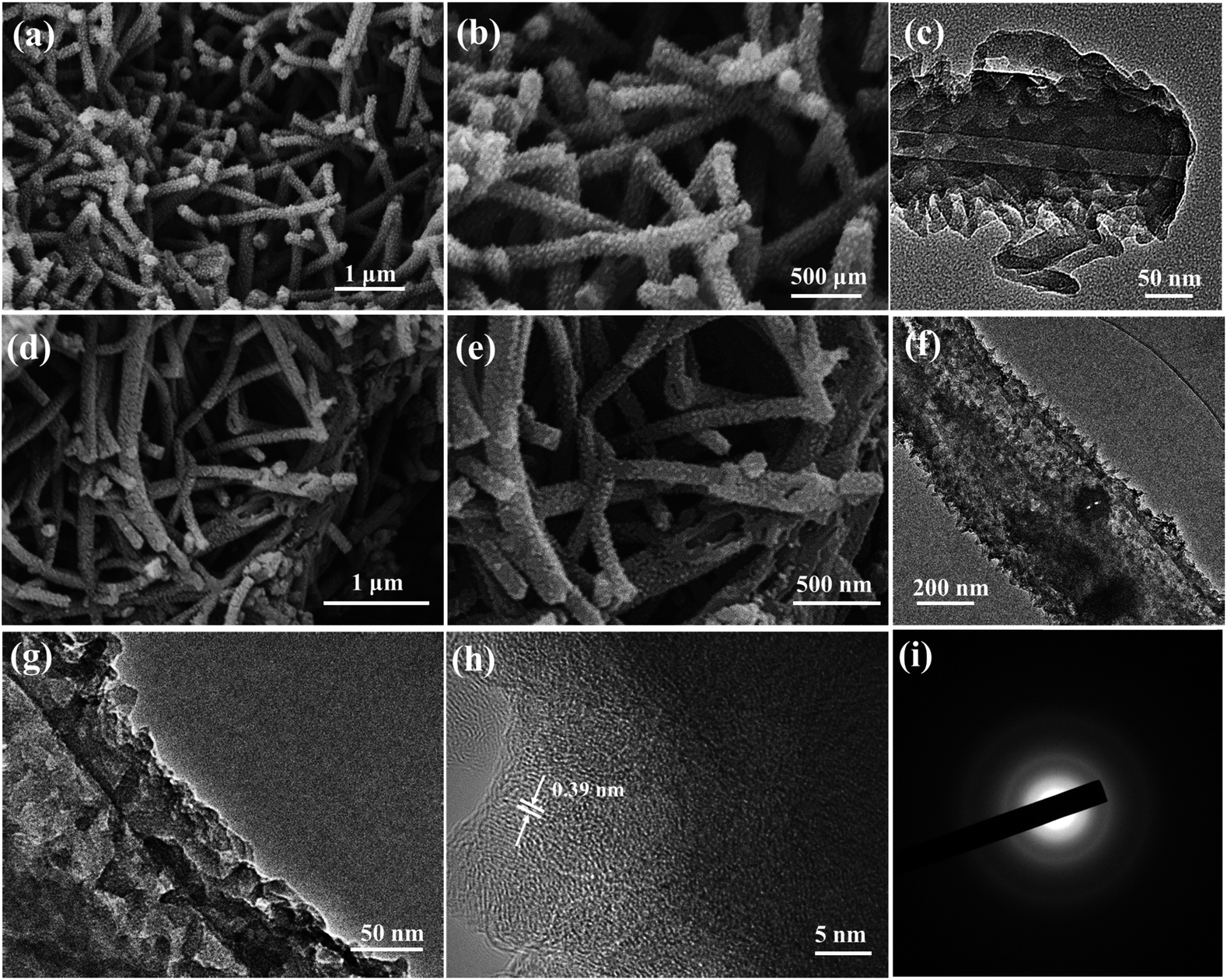 | ||
| Fig. 2 SEM images of the hierarchical PNF precursor (a and b) and N/S-HCNFs (d and e). TEM images of polyaniline nanofibers (c) and N/S-HCNFs (f–h). SAED pattern (i) of the N/S-HCNFs. | ||
In order to further understand the crystal phase and the pore structure of N/S-HCNFs, XRD, Raman spectroscopy and nitrogen adsorption/desorption measurements were performed. The XRD patterns of PNFs, N/S-HCNFs, N-HCNFs, and N-n-HCNFs are shown in Fig. 3a. The PNFs show broad peaks centered at 2θ = 20.5°, 25.6° and 30.1°, which are ascribed to (011), (020) and (200) crystal planes of polyaniline with the emeraldine salt structure, respectively.37 Furthermore, two broad diffraction peaks of (002) and (100) planes are observed for N/S-HCNFs, N-HCNFs, and N-n-HCNFs, which are characteristic of their disordered carbon structure. No diffraction peaks of sulfur are found in the XRD patterns of N/S-HCNFs, indicating a total carbonization of polyaniline. Based on the specific position of the (002) diffraction peak, the peaks for N/S-HCNFs and N-HCNFs are centered at 23.09° and 24.06°, respectively, indicating more lattice distortion and defects. According to Bragg's equation, the calculated interlayer spacing increased from 0.3481 to 0.3674 nm, proving that S-doping can enlarge the interlayer distance of carbon. Since sulfur has a larger covalent diameter than that of carbon, the replacement of carbon by sulfur will lead to an increase in the spacing between adjacent carbon sheets.38 Raman spectra (Fig. 3b) show the characteristic peaks of typical carbon materials at ≈1350 cm−1 (D band) and ≈1590 cm−1 (G band). The N/S-HCNF sample exhibits a higher intensity ratio of D vs. G bands (ID/IG = 0.93) compared with N-HCNFs (ID/IG = 0.90) and N-n-HCNFs (ID/IG = 0.89). This can be reasonably due to the appropriate doping with S for generating more defects in the carbon material. The N2 adsorption/desorption isotherms of the samples are shown in Fig. 3c. Comparatively, the N/S-HCNFs show a high surface area of 397.7 m2 g−1, while the N-HCNFs and N-n-HCNFs show relatively smaller surface areas of 138.3 and 13.6 m2 g−1, respectively. Obviously, the high surface area of N/S-HCNFs results from the 1D hollow structure and the sulfur treatment. Fig. 3d shows the pore size distributions of all samples, demonstrating the existence of abundant micropores in N/S-HCNFs. The large surface area and high pore volume of N/S-HCNFs will provide abundant and enough transport channels for fast Na+ insertion/extraction, and ensure adequate contact between the electrolyte and the active material.
 | ||
| Fig. 3 XRD patterns (a), Raman spectra (b), nitrogen adsorption–desorption isotherms (c) and pore size distribution (d) of the as-synthesized N/S-HCNFs, N-HCNFs, PNFs and N-n-HCNFs. | ||
The XPS data were used to analyze the chemical bonding configuration of the N/S-HCNFs. The full survey spectra of the as-prepared N/S-HCNFs clearly indicate the presence of C, N, O, and S elements on the surface (Fig. 4a). As illustrated in Fig. 4b, the C 1s peak of N/S-HCNFs is disintegrated into four peaks at 284.7, 285.7, 287.4, and 290.5 eV, corresponding to C![[double bond, length as m-dash]](https://www.rsc.org/images/entities/char_e001.gif) C,39 C–N,40 C–S,41 and O–CO,42 respectively. Moreover, the N 1s peak is decomposed into three peaks centered at 397.8,43 399.7,44 and 400.9 eV,45 which are consistent with pyridinic N, pyrrolic N, and quaternary N (Fig. 4c). The total N content is about 7.01% in the N/S-HCNF sample, which is lower than that (about 7.87%) of N-HCNFs (see Table S1 and Fig. S4 in the ESI†). It is well known that N-doping can generate some extrinsic defects and increase reactivity and electron conductivity.46Fig. 4d shows the high-resolution S 2p spectrum of N/S-HCNFs. It can be found that the sulfur in N/S-HCNFs exists in three different chemical states with a content of 3.15% (Table S1, ESI†), which are attributed to C–Sn–C (n = 1 or 2) bonds, conjugated –CS– bonds, and oxidized (–SOn–) bonds.47 This result confirms that sulfur has been successfully embedded into the hollow carbon nanofibers.34 Meanwhile, compared with N-HCNFs, N/S-HCNFs will generate more external defects and active sites. Such topological defects as well as active sites can adsorb more sodium ions, thereby improving sodium storage capacities.
C,39 C–N,40 C–S,41 and O–CO,42 respectively. Moreover, the N 1s peak is decomposed into three peaks centered at 397.8,43 399.7,44 and 400.9 eV,45 which are consistent with pyridinic N, pyrrolic N, and quaternary N (Fig. 4c). The total N content is about 7.01% in the N/S-HCNF sample, which is lower than that (about 7.87%) of N-HCNFs (see Table S1 and Fig. S4 in the ESI†). It is well known that N-doping can generate some extrinsic defects and increase reactivity and electron conductivity.46Fig. 4d shows the high-resolution S 2p spectrum of N/S-HCNFs. It can be found that the sulfur in N/S-HCNFs exists in three different chemical states with a content of 3.15% (Table S1, ESI†), which are attributed to C–Sn–C (n = 1 or 2) bonds, conjugated –CS– bonds, and oxidized (–SOn–) bonds.47 This result confirms that sulfur has been successfully embedded into the hollow carbon nanofibers.34 Meanwhile, compared with N-HCNFs, N/S-HCNFs will generate more external defects and active sites. Such topological defects as well as active sites can adsorb more sodium ions, thereby improving sodium storage capacities.
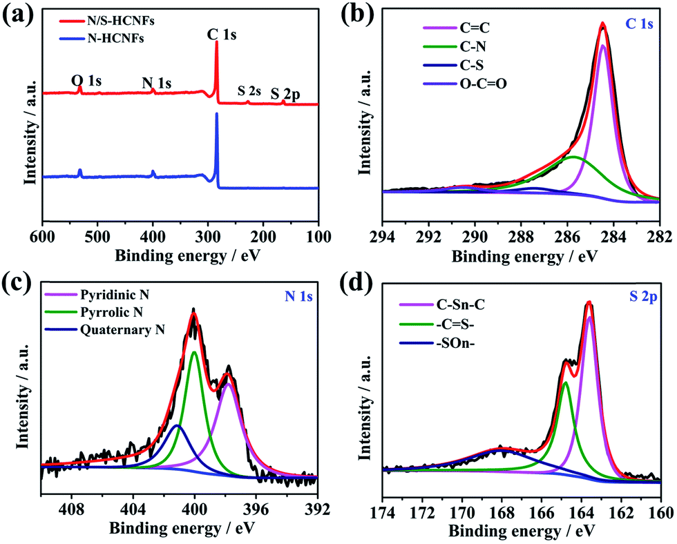 | ||
| Fig. 4 XPS survey spectra of N-HCNFs and N/S-HCNFs (a); C 1s (b), N 1s (c), and S 2p (d) spectra of N/S-HCNFs. | ||
Electrochemical performance
Sodium-ion half-cell performance
To further describe the electrochemical behavior of N/S-HCNFs, CV and GCD tests were performed. In order to demonstrate the advantage of N/S-HCNFs, the Na-storage performance of N-HCNFs and N-n-HCNFs is also tested under the same mass loading. Fig. 5a–c reveal the first three CV curves of N/S-HCNFs-800, N-HCNFs and N-n-HCNFs at a scan rate of 0.1 mV s−1 between 0.01 and 3.0 V (vs. Na/Na+). During the first negative scan, the peaks were present at 0.8 and 1.2 V for all samples, which were attributed to the decomposition of the electrolyte, the irreversible reaction of Na+ ions with the surface functional groups and the formation of a solid electrolyte interface (SEI) film. After the initial cycle, these peaks could disappear.48 The peaks in the potential range of 0.01 to 0.1 V can be ascribed to Na+ insertion/extraction in the carbon materials. However, the CV curves of N/S-HCNFs-800 are quite different from those of N-HCNFs and N-n-HCNFs. There is an additional reduction peak at 1.1 V from the beginning of the 2nd cycle of N/S-HCNFs, indicating a reduction reaction between Na and S, and there is a corresponding anodic peak at 1.85 V in the reverse process.49,50 This phenomenon is in agreement with that of the previously reported S-doped carbon in Na-storage and Na–S batteries.51 In the subsequent cycles, the CV curves of the N/S-HCNFs-800 electrode almost overlapped, which shows excellent reversibility of the N/S-HCNF electrodes. Fig. 5d–f show the first three GCD profiles of the three samples at a current density of 0.05 A g−1. During the first discharge cycle, the GCD profiles of the N-HCNFs and N-n-HCNFs are typical of hard carbon. In contrast, a discharge plateau at ∼1 V is clearly seen for the N/S-HCNFs-800. As shown in Fig. 5d, an obvious sloping platform located at ∼1.5 V can be observed in the charge curves, which indicates that the partial capacity for N/S-HCNFs is contributed by faradaic reactions of Na+ with the covalently bonded S. The first discharge (charge) capacities of N/S-HCNFs-800, N-HCNFs, and N-n-HCNFs anodes were 1286 (452), 912 (255), and 669 (151) mA h g−1, respectively, corresponding to an initial coulombic efficiency (ICE) of 35.1%, 27.9%, and 22.5%, respectively. The low ICE is caused by the formation of the SEI layer and the irreversible side reactions between Na+ and surface functional groups. After several cycles, the coulombic efficiency could be completely increased and could approach 100%.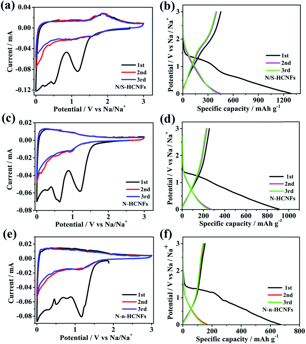 | ||
| Fig. 5 CV curves of N/S-HCNFs (a), N-HCNFs (b) and N-n-HCNFs (c) at a scan rate of 0.1 mV s−1; the first three GCD profiles of N/S-HCNFs (d), N-HCNFs (e), and N-n-HCNFs (f) at 0.05 A g−1. | ||
Fig. 6a shows the rate performance of N/S-HCNFs-800, N-HCNFs and N-n-HCNFs, tested at different current densities from 0.05 to 10 A g−1 for 5 cycles. Compared with the other two samples, N/S-HCNFs-800 show an excellent rate performance, with reversible capacities of 446.9, 349.2, 312.6, 275.8, 237.8, 215.6, 198.3, and 185.1 mA h g−1 obtained at 0.05, 0.1, 0.2, 0.5, 1, 2, 5 and 10 A g−1 with 5 cycles at each step. After the high-rate measurement, a high specific capacity of 348.3 mA h g−1 at 0.1 A g−1 could still be recovered for the N/S-HCNFs-800 electrode. For N-HCNFs without S doping, when the current density increased to 10 A g−1, the N-HCNF electrode delivers a low specific capacity of about 95.7 mA h g−1. Comparatively, the capacity of the N-n-HCNF electrode is only 58.7 mA h g−1 at 10 A g−1. The GCD curves at different current densities further confirm these rate results (Fig. 6c and S5 in the ESI†). Thus, the N/S-HCNF electrode exhibits much better rate performance than other control samples. Further, compared with the already reported carbon materials in the literature52–54 (Table S2, ESI†), the N/S-HCNFs have an excellent sodium-storage performance.
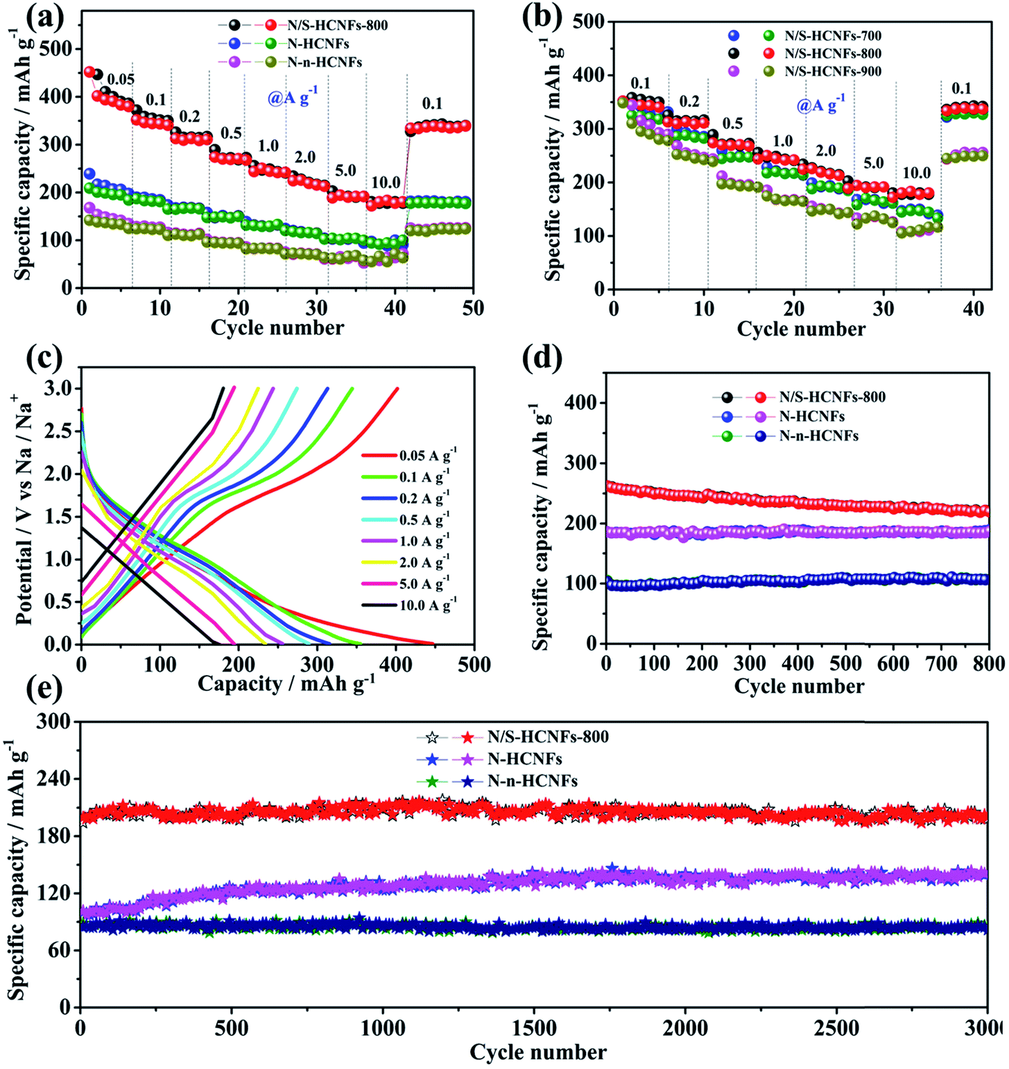 | ||
| Fig. 6 Electrochemical performance of the as-synthesized N/S-HCNFs, N-HCNFs, and N-n-HCNFs. Rate performance (a and b). GCD curves at different current densities (c). Cycling performance at a current density of 0.5 A g−1 (d) and 5.0 A g−1 (e). | ||
Generally, the N and S contents and the graphitization degree in N/S-HCNFs will be significantly changed with annealing temperature (see Table S1, ESI†), which can further affect the electrochemical performance. Here we also compare the sodium-storage performance of the N/S-HCNF samples at different annealing temperatures (700, 800, and 900 °C). Fig. 6b presents the specific capacities of N/S-HCNFs-700, N/S-HCNFs-800 and N/S-HCNFs-900 at different current densities. Obviously, the N/S-HCNFs-800 electrode showed relatively higher capacities (185.1 mA h g−1 at 10 A g−1) than those of N/S-HCNFs-700 (147.9 mA h g−1 at 10 A g−1) and N/S-HCNFs-900 (111.6.1 mA h g−1 at 10 A g−1). In addition, N/S-HCNFs-700 and N/S-HCNFs-900 are superior to N-HCNFs without S doping. These results indicate that the optimal temperature for the formation of N/S-HCNFs is 800 °C.
Fig. 6d shows the cycling performance of the N/S-HCNFs-800, N-HCNF and N-n-HCNF electrodes at a current density of 0.5 A g−1. After 800 cycles, the N/S-HCNF electrode still exhibits a high specific reversible capacity of 224.7 mA h g−1. Moreover, N-HCNFs and N-n-HCNFs retain reversible capacities of 182.5 and 104.6 mA h g−1, respectively. Apparently, N/S-HCNFs-800 has a much higher reversible capacity than N-HCNFs and N-n-HCNFs, due to the synergy effects of the hollow nanofiber structure and N/S co-doping. The GCD curves at the 1st, 300th, and 800th cycle at 0.5 A g−1 further demonstrate these cycling results (ESI†). To further clarify the significant Na-storage performance at relatively high current densities, all samples were evaluated at 5.0 A g−1 for long cycling. As shown in Fig. 6e, the N/S-HCNFs-800 shows outstanding cycling performance, and the capacity is maintained at 202.3 mA h g−1 even after 3000 cycles. The overall capacity decay can be neglected. The coulombic efficiency approaches 100%, indicating stable reversibility. The N-HCNF and N-n-HCNF electrodes also exhibit good cycling ability, but their specific capacities after 3000 cycles are relatively low in comparison to that of N/S-HCNFs. In Fig. 6e, the capacity increase for N-HCNFs may be caused by the activation and the formation of a stable SEI film.
In order to evaluate the electrochemical kinetics of N/S-HCNFs, the electrode was further explored by CV using different scan rates ranging from 0.5 to 10 mV s−1, and the capacitive contribution to the charge storage was evaluated. The original shape of the CV curves of the N/S-HCNF electrode was well maintained with increasing the scan rate to 10 mV s−1 (Fig. 7a). This result also reveals the fast diffusion of Na ions into the N/S-HCNFs. The degree of the capacitive effect can be qualitatively calculated based on the relationship between the measured current (i) and the scan rate (ν) from the CV curves: i = aνb, where a and b are adjustable parameters.55 The b value can be obtained from the slope of the log i vs. logν plot (Fig. S7 in the ESI†). Fig. 7b shows the separation of the diffusion controlled and the capacitive contribution of the N/S-HCNF electrode. The diffusion-type contribution reduced gradually with increasing scan rate (Fig. 7c), but the capacitive-type contribution was enhanced. At a scan rate of 10 mV s−1, 88% of the total capacity is identified as the capacitive contribution for the N/S-HCNF electrode, which is higher than 83% for the N-HCNF sample (Fig. 7d–f). This high capacitive contribution may be ascribed to the S-doping-induced larger interlayer distance, lower Na+ diffusion barrier and higher electronic conductivity facilitating the Na+-ion insertion/extraction. This result indicates that the N/S-HCNFs are beneficial to fast kinetics of Na-ion storage.
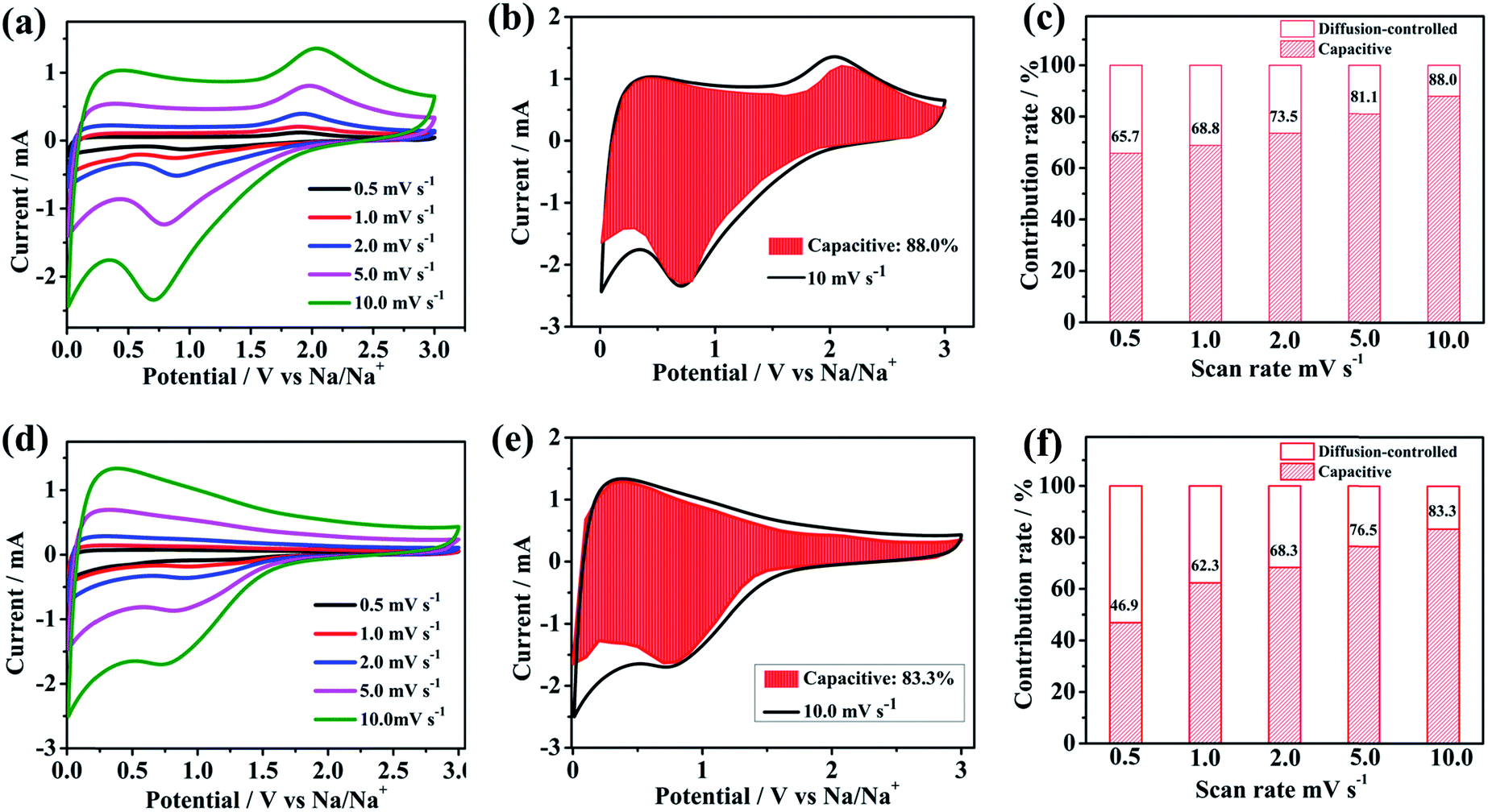 | ||
| Fig. 7 CV curves of (a) N/S-HCNF (d) and N-HCNF electrodes at different scan rates. The capacitive contribution to the sodium ion storage marked by the shaded region at a scan rate of 10.0 mV s−1 of the as-synthesized (b) N/S-HCNFs and (e) N-HCNFs. Normalized contribution ratio of capacitive capacities at different scan rates of the as-synthesized (c) N/S-HCNFs and (f) N-HCNFs. | ||
In order to further indicate the structural merits of N/S-HCNFs, the electrochemical impedance spectroscopy (EIS) of N/S-HCNFs-800, N-HCNFs and N-n-HCNFs is shown in Fig. S8 in the ESI.† The three EIS curves have a common feature, in which the intercept at the high-frequency end is equal to the electrolyte resistance (Rs), the semicircle size at the medium-frequency response is the charge-transfer resistance, and the low-frequency line is indicative of the Warburg impedance related to Na+ diffusion. Apparently, the diameter of the semicircle for N/S-HCNFs in the high-frequency region is significantly smaller than that for N-HCNFs and N-n-HCNFs. Specifically, the values of the charge-transfer resistance for N/S-HCNFs, N-HCNFs and N-n-HCNFs are about 125, 203 and 248 Ω, respectively, and the SEI film resistance is about 5.88, 12.68, 23.53 Ω, respectively. This result indicates that the N/S-HCNF electrode possesses lower charge-transfer impedance and SEI film resistance because of S-doping, which can result in rapid electron transport during the electrochemical sodium insertion/extraction reactions.
The excellent Na-storage properties of the N/S-HCNF electrode can be reasonably attributed to: (1) its hierarchical 1D hollow nanofiber structure, which reduces the mass-transfer resistance and provides sufficient active sites. (2) N, S-codoping in carbon, which results in the lowest Na+ adsorption energy compared to that of the pristine and N-doped carbon (see Fig. 1b), as previously confirmed by first-principles calculations.56,57 This indicates that the adsorption of Na+ onto the N/S-HCNFs is thermodynamically spontaneous. (3) The N/S codoping will increase the fermi level, which leads to a higher electronic conductivity facilitating electron transport. This was further demonstrated by EIS results (Fig. S8 in the ESI†). More importantly, S doping will enlarge the interlayer distance of carbon (Fig. 1b), which decreases the Na diffusion barrier and further contributes to the enhanced Na-adsorption stability. Therefore, N/S-HCNFs exhibit high Na-ion storage capacity and excellent rate/cycling stabilities. With this excellent anode candidate for hybrid NICs, the typical kinetics mismatch with the capacitive carbon cathode can be efficiently decreased.
Hybrid Na-ion capacitors
As shown in Fig. 8a, a NIC device is constructed using N/S-HCNFs as the anode and commercial AC as the cathode in 1 M NaClO4 in EC-DMC electrolyte solution. During the charge process, ClO4− ions are absorbed in the porous structure of AC, while Na ions from the electrolyte are inserted into N/S-HCNFs. The discharge process is the reverse of the charge process. Before fabricating the NIC, the N/S-HCNF electrode was pre-activated for 10 cycles at 0.1 A g−1 in a Na-ion half-cell to obtain high efficiency and then discharged to a cut-off voltage of 0.01 V. In addition, the electrochemical performance of AC as the cathode was investigated to evaluate the charge balance between the cathode and the anode in the NIC. The specific area of AC is up to 1357 m2 g−1. The detailed results of the AC cathode are shown in Fig. S3 and S9, ESI.† The typical linear GCD curves also confirm the EDLC mechanism. In the voltage window of 2.5–4.5 V (vs. Na/Na+), the discharge capacity of the BPC cathode is 75 mA h g−1 at a current density of 0.1 A g−1. Even at 10 A g−1, the specific capacity is still as high as 23 mA h g−1. After 2000 cycles at 5 A g−1, the capacity retention is up to 92%. According to the specific capacity values of the AC cathode and N/S-HCNF anode, the mass ratio of AC to N/S-HCNFs in the NIC is 3:1. The as-optimized “dual carbon” NIC device can be tested in a relatively large voltage window between 0 and 4.0 V.
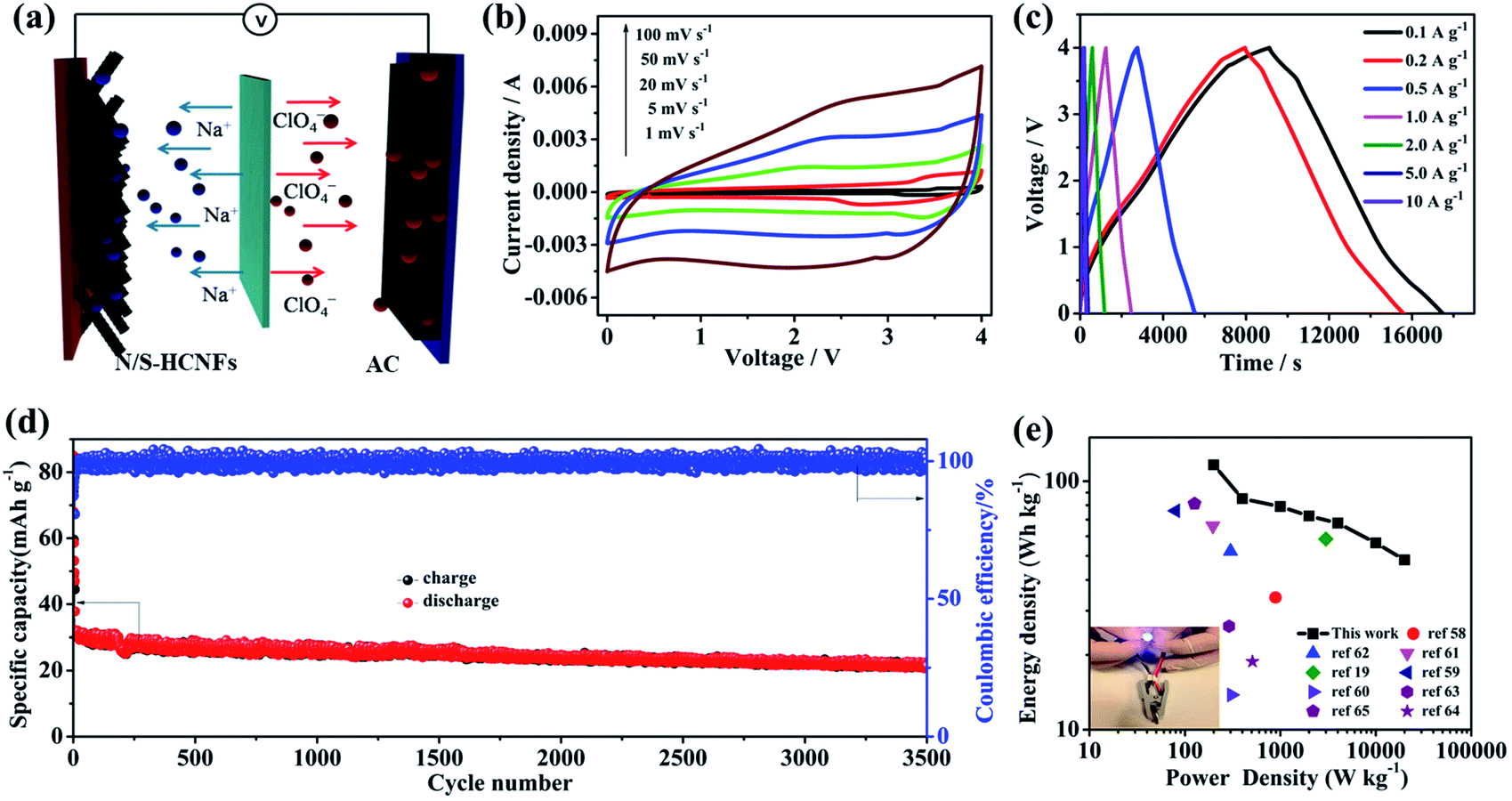 | ||
| Fig. 8 (a) Schematic representation of the NIC device made of the as-prepared N/S-HCNFs as the anode and commercial AC as the cathode. (b) CV curves at various scan rates from 1 to 100 mV s−1. (c) GCD curves of the as-assembled NIC at different current densities based on the total mass of N/S-HCNFs and AC. (d). Cycling performance of the AC//N/S-HCNF NIC between 0 and 4.0 V at a current density of 2 A g−1. (e) The Ragone plot (energy density vs. power density) of the present AC//N/S-HCNF NIC and comparison with the results of other reports, and lighting a blue LED (inset) using the AC//N/S-HCNF NIC. | ||
Fig. 8b shows the CV curves of the AC//N/S-HCNF NIC device at different scan rates from 1 to 100 mV s−1 in the voltage window of 0–4.0 V. The CV curves show a slight deviation from the ideal rectangular shape owing to the synergistic effect of two different charge-storage mechanisms. As the scan rate increases to an ultrahigh scan rate of 100 mV s−1, the shape of the CV curve is still maintained without serious distortion, which is indicative of high reversibility and excellent rate performance, respectively. The charge–discharge curves of the AC//N/S-HCNFs at various current densities exhibit an approximately linear slope as shown in Fig. 8c, indicating the combination of the insertion/extraction of Na+ ions in N/S-HCNFs and the capacitive AC cathode. The corresponding specific capacities (based on the total mass of active materials in both the cathode and anode) are 58.2, 42.5, 39.5, 36.2, 33.9, 28.2 and 24.1 mA h g−1 at 0.1, 0.2, 0.5, 1, 2, 5, and 10 A g−1, respectively (Fig. S10, ESI†). The capacity loss at a high current density is mainly due to the insufficient accessibility of electrolyte ions and the relatively large IR drop. Furthermore, relatively good cycling stability is obtained with 81% capacity retention after 3000 cycles at a current density of 2 A g−1, corresponding to a high coulombic efficiency of nearly 100% (Fig. 8d).
The Ragone plot (energy vs. power) of the AC//N/S-HCNF NIC device is presented in Fig. 8e. The specific values of energy density and power density are calculated according to the galvanostatic discharge curves. As expected, our NIC could deliver a high energy density of 116.4 W h kg−1 at a power density of 200 W kg−1. Even at a high power density of 20 kW kg−1, the NIC can still achieve 48.2 W h kg−1. It should be noted that the power density of 20 kW kg−1 (at 48.2 W h kg−1) corresponds to a full charge–discharge within 38 s, similar to capacitor features. In comparison, our NIC also exhibits better energy-storage performance than other AC-based NICs reported in ref. 19 and 58–65 (Table S3, ESI†). In addition, a light-emitting diode (LED) panel can be successfully powered by a single AC//N/S-HCNF NIC device (inset of Fig. 8e). The outstanding electrochemical performance of our dual-carbon NIC device fabricated here by using N/S-HCNFs as the anode and AC as the cathode can be attributed to the following aspects: (1) the N/S-HCNF anode possesses an interlayer spacing due to N/S co-doping, which promotes the fast diffusion of sufficient Na+ ions. (2) The large surface area and high pore volume as well as the 1D hollow fiber structure of N/S-HCNFs can greatly increase the transfer of ions and the contact of the electrolyte. (3) The dual-carbon configuration in the NIC may be beneficial for kinetics matching and structural stability, which lead to the improvement of electrochemical performance of the hybrid device.
Conclusions
In summary, N/S co-doped hollow carbon nanofibers have been synthesized successfully via a facile and controllable strategy, and their superior sodium-storage performance as an anode for NICs has been presented. N/S co-doping in carbon and the unique hierarchical hollow 1D fiber structure can lead to major capacity contribution. More importantly, N/S dual doping greatly decreases the mismatch of electrode kinetics between the cathode and anode of NICs, resulting in both high energy density and high power density. Ultimately, a high-performance dual-carbon NIC (AC//N/S-HCNFs) has been fabricated, which presents a high energy density (116.4 W h kg−1 at 200 W kg−1), a high power density (20 kW kg−1 at 48.2 W h kg−1), and a reasonably long cycling life (81% capacitance retention after 3000 cycles).Conflicts of interest
There are no conflicts to declare.Acknowledgements
The authors gratefully acknowledge the financial support by the National Natural Science Foundation of China (NSFC) Grants (no. 51702295, 51702294, and 51772116), the fund for the Academic Frontier Youth Team of HUST and the Natural Science Foundation of Zhejiang Grant (LY18B030004).References
- J. A. Rogers, T. Someya and Y. G. Huang, Science, 2010, 327, 1603–1607 CrossRef CAS PubMed.
- L. L. Peng, Y. Zhu, H. S. Li and G. H. Yu, Small, 2016, 12, 6183–6199 CrossRef CAS PubMed.
- M. Armand and J. M. Tarascon, Nature, 2008, 451, 652–657 CrossRef CAS PubMed.
- L. Croguennec and M. R. Palacin, J. Am. Chem. Soc., 2015, 137, 3140–3156 CrossRef CAS PubMed.
- V. Aravindan, J. Gnanaraj, Y. S. Lee and S. Madhavi, Chem. Rev., 2014, 114, 11619–11635 CrossRef CAS PubMed.
- H. S. Li, L. L. Peng, Y. Zhu, D. H. Chen, X. G. Zhang and G. H. Yu, Energy Environ. Sci., 2016, 9, 3399–3405 RSC.
- D. H. Chen, L. L. Peng, Y. F. Yuan, Y. Zhu, Z. W. Fang, C. S. Yan, G. Chen, R. Shahbazian-Yassar, J. Lu, K. Amine and G. H. Yu, Nano Lett., 2017, 17, 3907–3913 CrossRef CAS PubMed.
- L. L. Peng, P. Xiong, L. Ma, Y. F. Yuan, Y. Zhu, D. H. Chen, X. Y. Luo, J. Lu, K. Amine and G. H. Yu, Nat. Commun., 2017, 8, 15139–15149 CrossRef PubMed.
- Z. Q. Niu, J. Chen, H. H. Hng, J. Ma and X. D. Chen, Adv. Mater., 2012, 24, 4144–4150 CrossRef CAS PubMed.
- Z. S. Wu, Y. Sun, Y. Z. Tan, S. B. Yang, X. L. Feng and K. Mullen, J. Am. Chem. Soc., 2012, 134, 19532–19535 CrossRef CAS PubMed.
- L. F. Chen, X. D. Zhang, H. W. Liang, M. G. Kong, Q. F. Guan, P. Chen, Z. Y. Wu and S. H. Yu, ACS Nano, 2012, 6, 7092–7102 CrossRef CAS PubMed.
- G. G. Amatucci, F. Badway, A. Du Pasquier and T. Zheng, J. Electrochem. Soc., 2001, 148, A930–A939 CrossRef CAS.
- H. G. Jung, N. Venugopal, B. Scrosati and Y. K. Sun, J. Power Sources, 2013, 221, 266–271 CrossRef CAS.
- E. Lim, C. Jo, H. Kim, M. H. Kim, Y. Mun, J. Chun, Y. Ye, J. Hwang, K. S. Ha, K. C. Roh, K. Kang, S. Yoon and J. Lee, ACS Nano, 2015, 9, 7497–7505 CrossRef CAS PubMed.
- H. W. Wang, C. Guan, X. F. Wang and H. J. Fan, Small, 2015, 11, 1470–1477 CrossRef CAS PubMed.
- H. L. Wang, Z. W. Xu, Z. Li, K. Cui, J. Ding, A. Kohandehghan, X. H. Tan, B. Zahiri, B. C. Olsen, C. M. B. Holt and D. Mitlin, Nano Lett., 2014, 14, 1987–1994 CrossRef CAS PubMed.
- D. L. Chao, C. R. Zhu, P. H. Yang, X. H. Xia, J. L. Liu, J. Wang, X. F. Fan, S. V. Savilov, J. Y. Lin, H. J. Fan and Z. X. Shen, Nat. Commun., 2016, 7, 12122–12130 CrossRef CAS PubMed.
- Z. Chen, V. Augustyn, X. L. Jia, Q. F. Xiao, B. Dunn and Y. F. Lu, ACS Nano, 2012, 6, 4319–4327 CrossRef CAS PubMed.
- S. Y. Dong, L. F. Shen, H. S. Li, P. Nie, Y. Y. Zhu, Q. Sheng and X. G. Zhang, J. Mater. Chem. A, 2015, 3, 21277–21283 RSC.
- X. Wang, S. Kajiyama, H. Iinuma, E. Hosono, S. Oro, I. Moriguchi, M. Okubo and A. Yamada, Nat. Commun., 2015, 6, 6544–6550 CrossRef CAS PubMed.
- R. Thangavel, K. Kaliyappan, K. Kang, X. L. Sun and Y. S. Lee, Adv. Energy Mater., 2016, 6, 1502199–1502208 CrossRef.
- C. Bommier, D. Mitlin and X. Ji, Prog. Mater. Sci., 2018, 97, 170–203 CrossRef CAS.
- F. Li and Z. Zhou, Small, 2018, 14, 1702961–1702986 CrossRef PubMed.
- H. Hou, C. E. Banks, M. Jing, Y. Zhang and X. Ji, Adv. Mater., 2015, 27, 7861–7866 CrossRef CAS PubMed.
- Z. Huang, H. Hou, Y. Zhang, C. Wang, X. Qiu and X. Ji, Adv. Mater., 2017, 29, 2372–2379 Search PubMed.
- J. Ding, H. L. Wang, Z. Li, K. Cui, D. Karpuzov, X. H. Tan, A. Kohandehghan and D. Mitlin, Energ Environ. Sci., 2015, 8, 941–955 RSC.
- S. H. Li, D. K. Huang, B. Y. Zhang, X. B. Xu, M. K. Wang, G. Yang and Y. Shen, Adv. Energy Mater., 2014, 4, 1301655–1301662 CrossRef.
- B. J. Yang, J. T. Chen, S. L. Lei, R. S. Guo, H. X. Li, S. Q. Shi and X. B. Yan, Adv. Energy Mater., 2018, 8, 1702409–1702420 CrossRef.
- H. Liu, M. Q. Jia, N. Sun, B. Cao, R. J. Chen, Q. Z. Zhu, F. Wu, N. Qiao and B. Xu, ACS Appl. Mater. Interfaces, 2015, 7, 27124–27130 CrossRef CAS PubMed.
- Z. H. Wang, L. Qie, L. X. Yuan, W. X. Zhang, X. L. Hu and Y. H. Huang, Carbon, 2013, 55, 328–334 CrossRef CAS.
- X. H. Liu, J. Zhang, S. J. Guo and N. Pinna, J. Mater. Chem. A, 2016, 4, 1423–1431 RSC.
- L. Qie, W. M. Chen, X. Q. Xiong, C. C. Hu, F. Zou, P. Hu and Y. H. Huang, Adv. Sci., 2015, 2, 1500195–1500201 Search PubMed.
- S. L. Zhang, F. Yao, L. Yang, F. Z. Zhang and S. L. Xu, Carbon, 2015, 93, 143–150 CrossRef CAS.
- N. An, Y. F. An, Z. G. Hu, Y. D. Zhang, Y. Y. Yang and Z. Q. Lei, RSC Adv., 2015, 5, 63624–63633 RSC.
- J. Yang, X. Zhou, D. Wu, X. Zhao and Z. Zhou, Adv. Mater., 2017, 29, 1–5 Search PubMed.
- L. F. Xiao, Y. L. Cao, J. Xiao, B. Schwenzer, M. H. Engelhard, L. V. Saraf, Z. M. Nie, G. J. Exarhos and J. Liu, Adv. Mater., 2012, 24, 1176–1181 CrossRef CAS PubMed.
- S. Komaba, W. Murata, T. Ishikawa, N. Yabuuchi, T. Ozeki, T. Nakayama, A. Ogata, K. Gotoh and K. Fujiwara, Adv. Funct. Mater., 2011, 21, 3859–3867 CrossRef CAS.
- Y. L. Cao, L. F. Xiao, M. L. Sushko, W. Wang, B. Schwenzer, J. Xiao, Z. M. Nie, L. V. Saraf, Z. G. Yang and J. Liu, Nano Lett., 2012, 12, 3783–3787 CrossRef CAS PubMed.
- S. J. Bradley, R. Kroon, G. Laufersky, M. Roding, R. V. Goreham, T. Gschneidtner, K. Schroeder, K. Moth-Poulsen, M. Andersson and T. Nann, Microchim. Acta, 2017, 184, 871–878 CrossRef CAS.
- L. M. Liu, W. Weng, X. Y. Dai, N. Liu, J. J. Yang, Y. X. Liang and X. Ding, RSC Adv., 2016, 6, 108362–108368 RSC.
- J. S. Kim, H. W. Yoo, H. O. Choi and H. T. Jung, Nano Lett., 2014, 14, 5941–5947 CrossRef CAS PubMed.
- S. Y. Tian, S. W. Yang, T. Huang, J. Sun, H. S. Wang, X. P. Pu, L. F. Tian, P. He, G. Q. Ding and X. M. Xie, Carbon, 2017, 111, 617–621 CrossRef CAS.
- T. Le, Y. Yang, Z. H. Huang and F. Y. Kang, J. Power Sources, 2015, 278, 683–692 CrossRef CAS.
- J. Li, F. Yu, M. R. Wang, Y. Q. Lai, H. Wang, X. K. Lei and J. Fang, Int. J. Hydrogen Energy, 2017, 42, 2996–3005 CrossRef CAS.
- X. T. Xu, L. K. Pan, Y. Liu, T. Lu and Z. Sun, J. Colloid Interface Sci., 2015, 445, 143–150 CrossRef CAS PubMed.
- Z. Luo, S. Liu, Y. Cai, S. Li, A. Pan and S. Liang, Sci. Bull., 2018, 63, 126–132 CrossRef CAS.
- H. Ding, J. S. Wei and H. M. Xiong, Nanoscale, 2014, 6, 13817–13823 RSC.
- T. H. Hwang, D. S. Jung, J. S. Kim, B. G. Kim and J. W. Choi, Nano Lett., 2013, 13, 4532–4538 CrossRef CAS PubMed.
- X. L. Wang, G. Li, F. M. Hassan, J. D. Li, X. Y. Fan, R. Batmaz, X. C. Xiao and Z. W. Chen, Nano Energy, 2015, 15, 746–754 CrossRef CAS.
- K. Tang, L. J. Fu, R. J. White, L. H. Yu, M. M. Titirici, M. Antonietti and J. Maier, Adv. Energy Mater., 2012, 2, 873–877 CrossRef CAS.
- T. H. Hwang, D. S. Jung, J. S. Kim, B. G. Kim and J. W. Choi, Nano Lett., 2013, 13, 4532–4538 CrossRef CAS PubMed.
- D. F. Xu, C. J. Chen, J. Xie, B. Zhang, L. Miao, J. Cai, Y. H. Huang and L. N. Zhang, Adv. Energy Mater., 2016, 6, 1501929–15501936 CrossRef.
- J. C. Ye, J. Zang, Z. W. Tian, M. S. Zheng and Q. F. Dong, J. Mater. Chem. A, 2016, 4, 13223–13227 RSC.
- L. Q. Yu, H. H. Song, Y. T. Li, Y. X. Chen, X. H. Chen, J. S. Zhou, Z. K. Ma, X. Y. Wan, P. Tian and J. Wu, Electrochim. Acta, 2016, 218, 285–293 CrossRef CAS.
- D. L. Chao, P. Liang, Z. Chen, L. Y. Bai, H. Shen, X. X. Liu, X. H. Xia, Y. L. Zhao, S. V. Savilov, J. Y. Lin and Z. X. Shen, ACS Nano, 2016, 10, 10211–10219 CrossRef CAS PubMed.
- Y. Qiao, M. Ma, Y. Liu, S. Li, Z. Lu, H. Yue, H. Dong, Z. Cao, Y. Yin and S. Yang, J. Mater. Chem. A., 2016, 4, 15565–15574 RSC.
- D. Xu, C. Chen, J. Xie, B. Zhang, L. Miao, J. Cai, Y. Huang and L. Zhang, Adv. Energy Mater., 2016, 6, 1501929 CrossRef.
- J. Yin, L. Qi and H. Y. Wang, ACS Appl. Mater. Interfaces, 2012, 4, 2762–2768 CrossRef CAS PubMed.
- E. Lim, C. Jo, M. S. Kim, M. H. Kim, J. Chun, H. Kim, J. Park, K. C. Roh, K. Kang, S. Yoon and J. Lee, Adv. Funct. Mater., 2016, 26, 3711–3719 CrossRef CAS.
- R. Ding, L. Qi and H. Wang, Electrochim. Acta, 2013, 114, 726–735 CrossRef CAS.
- Z. L. Jian, V. Raju, Z. F. Li, Z. Y. Xing, Y. S. Hu and X. L. Ji, Adv. Funct. Mater., 2015, 25, 5778–5785 CrossRef CAS.
- S. J. Wang, R. T. Wang, Y. B. Zhang, D. D. Jin and L. Zhang, J. Power Sources, 2018, 379, 33–40 CrossRef CAS.
- Q. Zhao, D. Yang, A. K. Whittaker and X. S. Zhao, J. Power Sources, 2018, 396, 12–18 CrossRef CAS.
- H. Gu, L. Kong, H. Cui, X. Zhou, Z. Xie and Z. Zhou, J. Energy Chem., 2018, 01, 12–18 Search PubMed.
- Y.-E. Zhu, L. Yang, J. Sheng, Y. Chen, H. Gu, J. Wei and Z. Zhou, Adv. Energy Mater., 2017, 7, 1701222 CrossRef.
Footnote |
| † Electronic supplementary information (ESI) available. See DOI: 10.1039/c8na00219c |
| This journal is © The Royal Society of Chemistry 2019 |