
A microfluidic co-cultivation platform to investigate microbial interactions at defined microenvironments†
Alina
Burmeister
 ad,
Fabienne
Hilgers
b,
Annika
Langner
a,
Christoph
Westerwalbesloh
a,
Yannic
Kerkhoff
d,
Niklas
Tenhaef
a,
Thomas
Drepper
b,
Dietrich
Kohlheyer
ac,
Eric
von Lieres
a,
Stephan
Noack
a and
Alexander
Grünberger
*ad
ad,
Fabienne
Hilgers
b,
Annika
Langner
a,
Christoph
Westerwalbesloh
a,
Yannic
Kerkhoff
d,
Niklas
Tenhaef
a,
Thomas
Drepper
b,
Dietrich
Kohlheyer
ac,
Eric
von Lieres
a,
Stephan
Noack
a and
Alexander
Grünberger
*ad
aInstitute of Bio- and Geosciences, IBG-1: Biotechnology, Forschungszentrum Jülich, 52425 Jülich, Germany
bInstitute of Molecular Enzyme Technology, Heinrich-Heine-University Düsseldorf, Forschungszentrum Jülich, 52428 Jülich, Germany
cRWTH Aachen University, Microscale Bioengineering (AVT.MSB), 52074 Aachen, Germany
dMultiscale Bioengineering, Bielefeld University, Universitätsstr. 25, 33615 Bielefeld, Germany. E-mail: alexander.gruenberger@uni-bielefeld.de; Tel: +49 521 106 5289
First published on 29th November 2018
Abstract
Interspecies interactions inside microbial communities bear a tremendous diversity of complex chemical processes that are by far not understood. Even for simplified, often synthetic systems, the interactions between two microbes are barely revealed in detail. Here, we present a microfluidic co-cultivation platform for the analysis of growth and interactions inside microbial consortia with single-cell resolution. Our device allows the spatial separation of two different microbial organisms inside adjacent microchambers facilitating sufficient exchange of metabolites via connecting nanochannels. Inside the cultivation chambers cell growth can be observed with high spatio-temporal resolution by live-cell imaging. In contrast to conventional approaches, in which single-cell activity is typically fully masked by the average bulk behavior, the small dimensions of the microfluidic cultivation chambers enable accurate environmental control and observation of cellular interactions with full spatio-temporal resolution. Our method enables one to study phenomena in microbial interactions, such as gene transfer or metabolic cross-feeding. We chose two different microbial model systems to demonstrate the wide applicability of the technology. First, we investigated commensalistic interactions between an industrially relevant L-lysine-producing Corynebacterium glutamicum strain and an L-lysine auxotrophic variant of the same species. Spatially separated co-cultivation of both strains resulted in growth of the auxotrophic strain due to secreted L-lysine supplied by the producer strain. As a second example we investigated bacterial conjugation between Escherichia coli S17-1 and Pseudomonas putida KT2440 cells. We could show that direct cell contact is essential for the successful gene transfer via conjugation and was hindered when cells were spatially separated. The presented device lays the foundation for further studies on contactless and contact-based interactions of natural and synthetic microbial communities.
Introduction
Microbial communities are complex heterogeneous systems with diverse metabolic activities and ecological dependencies. Most interactions inside these communities have not yet been analyzed in detail due to their complexity and missing experimental setups for analysis. Intra- and interspecies microbial interactions are ubiquitous in nature and play a pivotal role in nearly every ecosystem. Most microorganisms interfere not only with each other but also with higher organisms.1 A well-known example is the symbiotic interaction of nitrogen-fixing bacteria with root nodules. These bacteria live inside the plant's roots and supply them with essential nitrogen, while they obtain carbohydrates from the plant in return.2 Another evidence for the importance of interactions inside bacterial communities in nature is the great discrepancy between the number of bacterial strains present in an environmental sample and the number of bacterial strains that can be cultivated in vitro.3 This unculturability of most bacteria in a monoculture is still a major problem for systematic studies of bacterial diversity.4 One reason for the unculturability of many laboratory strains is suspected to be the missing knowledge on symbiotic interactions within communities.3 The metabolic interactions are of vital importance for the growth of auxotrophic bacteria and can hardly be mimicked a priori under laboratory conditions.4Humans have made use of bacterial interplays for decades, mainly for food production or environmental tasks, such as wastewater treatment or bioremediation.1 In contrast to these rather complex communities with undefined substrates, synthetic microbial consortia are being developed as a minimalistic approach to better understand and make use of bacterial interactions.5 Hence the development of more defined and controllable engineered synthetic consortia in biotechnological production processes is gaining more and more interest.6–8 New applications include, for example, the production of ethanol,9 hydrogen,10 and biopolymers.11 Many other publications demonstrate that a wide range of products from bulk chemicals9 to high value products, such as taxadiene,12 can be produced by a synthetic microbial consortium.
Co-cultures have many advantages compared to mono-cultures as they can perform more complex metabolic tasks and seem to be more robust to environmental changes.13 To reveal and understand the whole potential of microbial interactions, in silico models have been developed and tested for consortia of different complexity.8,14 Computational models can help to design new synthetic co-cultures, yet practical analytical tools for precise analysis of interactions between different strains in a co-culture are lacking.
Single-cell analysis methods for heterogeneity studies, such as flow cytometry (FC) are not suitable for interaction studies. This method provides only a snapshot of a population at a specific time point, but no knowledge about cellular interactions or time-dependent cell behavior is gained.15
To fully understand microbial interactions under defined conditions, a small-scale approach with single-cell resolution is essential, which can be realized with microfluidic cultivation tools.16 However, not all microfluidic tools are suitable for the analysis of bacterial co-cultures. For example, droplet microfluidic systems allow screening for interaction, but the mechanisms remain mostly hidden as the local microenvironment is weakly defined, and nutrients are limited due to small medium volumes. Therefore microfluidic devices based on well-defined cultivation chambers in combination with time-lapse imaging to achieve single-cell resolution and high temporal resolution appear to be a suitable choice.16
Various microfluidic co-cultivation devices have been developed, mainly with a focus on mammalian cell culture. In contrast, microfluidic systems for the analysis of microbial consortia are still rare,17,18 and only some microfluidic systems with different working principles have been reported so far that allow defined co-cultivation of microbial cells (Table 1). Microdroplets, microwells, microhabitat structures and microchambers lack defined and controlled environmental conditions. Due to the batch cultivation principle within these devices, the environmental conditions are permanently changing.19–23 In contrast, the reported “microfluidic single-cell chemostat” from Moffitt et al.24 allows for continuous medium supply and exchange of medium. The drawback of the system is the agarose pad-based cultivation region, in which exchanged metabolites accumulate over time and thus lead to different unknown substrate concentrations during cultivation time.24 PDMS-based monolayer growth chambers are the only reported systems with defined microenvironments and single-cell resolution but were not applied for co-cultivation studies before.25 Long-term studies could be problematic, because in a commensalistic interaction, for example the slower growing auxotrophic strain will be overgrown very fast (Fig. S1†).
| System | Defined microenvironment | Single-cell resolution | Contactless studies | Contact-based studies | References |
|---|---|---|---|---|---|
| Microdroplets | No | No | No | Yes | Park et al.19 |
| Microwells | No | No | Yes | No | Kim et al.20 |
| Microhabitat structures | No | No | No | Yes | Keymer et al.21 |
| Hol et al.22 | |||||
| Microchambers with porous membrane | No | No | Yes | No | Nagy et al.23 |
| Single-cell chemostat | No | Yes | Yes | No | Moffitt et al.24 |
| Monolayer growth chambers | Yes | Yes | No | Yes | Grünberger et al.25 |
In this work, we developed a microfluidic system for the cultivation of two different bacterial strains or species under defined and controllable environmental conditions allowing continuous observation of microbial processes over time. It consists of cultivation chambers with interconnecting nanochannels for short diffusion distances and fast exchange of metabolites between the two chamber compartments. We show the performance of our device on two examples of microbial model systems. In the first model system, commensalism based on a synthetic co-culture of two C. glutamicum strains was investigated. In the second model system, the gene transfer between E. coli and P. putida cells – presumably a contact-dependent interaction via conjugation – was analyzed.
Materials and methods
Bacterial strains and plasmids
All bacterial strains, plasmids and oligonucleotides used in this study are listed in Table 2.| Strain, plasmids, oligonucleotides | Relevant features, description or sequencea | References |
|---|---|---|
| a Underlined sequences indicate inserted restriction sites. | ||
| Strains | ||
| C. glutamicum ΔlysA pEKEX2-eYFP | L-Lysine auxotrophic strain | 26, 27 |
| C. glutamicum DM1800 | L-Lysine producer strain | 28 |
| E. coli DH5α | F − Φ80lacZΔM15 Δ(lacZYA-argF) U169 recA1 endA1 hsdR17 phoA supE44 thi-1 gyrA96 relA1 deoR | 29, 30 |
| E. coli S17-1 | Ec294::[RP4-2 (TcR::Mu)(KmR::Tn7)] recA, thi, pro, hsdR−hsdM+ TpR SmR, donor strain for conjugational plasmid transfer | 31 |
| P. putida KT2440 | Wild type, recipient for conjugational plasmid transfer | 32, 33 |
| Plasmids | ||
| pRhokHi-2-EYFP | CmR, derivative of mobilizable broad host range vector pBBR1-MCS-2 carrying the YFP-encoding gene under control of the constitutive PaphII promoter | 34 |
| pJT'Tmcs | AmpR, GmR, vector for Ptac and tac RBS controlled expression, non-mobilizable | 35 |
| pJT'Tmcs-mCherry | pJT'Tmcs derivative for constitutive mCherry reporter gene expression | This work |
| Oligonucleotides | ||
| 1 (XhoI_mCherry_fw) | Binds at the 5′ end of the mCherry gene, contains an XhoI site for cloning. Sequence: 5′-ATAT![[C with combining low line]](https://www.rsc.org/images/entities/char_0043_0332.gif) ![[T with combining low line]](https://www.rsc.org/images/entities/char_0054_0332.gif) ![[G with combining low line]](https://www.rsc.org/images/entities/char_0047_0332.gif) ![[A with combining low line]](https://www.rsc.org/images/entities/char_0041_0332.gif) ATGGTGAGCAAGGGCGAGGA-3′ ATGGTGAGCAAGGGCGAGGA-3′ |
This work |
| 2 (XbaI_mCherry_rev) | Binds at the 3′ end of the mCherry gene, contains an XbaI site. Sequence: 5′-ATATTTACTTGTACAGCTCGTCCATGCC-3′ |
This work |
Basically, recombinant DNA techniques were carried out using E. coli DH5α for cloning as described by Sambrook et al.36 To construct a P. putida vector suitable for constitutive expression of the mCherry reporter, the respective gene was introduced into the plasmid pJT'Tmcs. Therefore, the mCherry DNA fragment was PCR-amplified using the primers 1 and 2 (Table 2). After XhoI and XbaI hydrolyzation, the PCR fragment was cloned into the likewise hydrolyzed vector backbone, yielding the vector pJT'Tmcs-mCherry. The resulting construct was verified via sequencing. Vector pJT'Tmcs-mCherry was transferred into P. putida KT2440 via electroporation as follows (modified after Tu et al., 201637). Overnight precultures were used to inoculate 8 mL of liquid LB medium starting with a defined cell density of 0.05 at a wavelength of 600 nm (OD600) for P. putida. After the cells reached an OD600 of 0.6, 1 mL of the culture was transferred into a 2 mL Eppendorf tube and centrifuged at 9000 rpm for 2 min at room temperature (24 °C). The supernatant was discarded, and the cells were resuspended in 1 mL of distilled water (dH2O) at room temperature; the washing step was repeated two times. Afterwards, the bacterial cells were again resuspended in 80 μL of dH2O (24 °C) and the tubes were kept at room temperature. 300 ng of the plasmid DNA was added to the prepared cells. The DNA–cell mixtures were then transferred into a 1 mm gap cuvette (24 °C) for electroporation at 1.8 kV. The cuvette was then flushed with 1 mL fresh LB medium and the cells were recovered by incubation at 30 °C for 2![[thin space (1/6-em)]](https://www.rsc.org/images/entities/char_2009.gif) hours. Finally, the cells were cultivated overnight on LB agar plates containing 25 μg mL−1 gentamicin. For the preparation of the donor strain, E. coli S17-1 cells were freshly transformed with the mobilizable expression plasmid pRhokHi-2-EYFP and plated on LB agar plates containing 50 μg mL−1 kanamycin overnight.
hours. Finally, the cells were cultivated overnight on LB agar plates containing 25 μg mL−1 gentamicin. For the preparation of the donor strain, E. coli S17-1 cells were freshly transformed with the mobilizable expression plasmid pRhokHi-2-EYFP and plated on LB agar plates containing 50 μg mL−1 kanamycin overnight.
Growth medium
E. coli liquid cultivations were performed in Lysogeny broth (LB) medium using 25 g L−1 Luria/Miller ready-to-use mix (Carl Roth, Karlsruhe, Germany). For solid LB plates 15 g L−1 agar-agar (Carl Roth, Karlsruhe, Germany) was added. Plasmid-containing strains were maintained by applying either 25 μg mL−1 of gentamicin or 50 μg mL−1 of kanamycin in both solid and liquid cultivation media. C. glutamicum strains were cultivated in defined CGXII medium at 30 °C.38 Before chip inoculation, C. glutamicum ΔlysA pEKEX2-eYFP was additionally supplied with 1.5 mmol L−1L-lysine in pre-culture medium. All media were autoclaved and additionally sterile filtered to prevent channel clogging during microfluidic growth experiments.Pre-cultivation of E. coli and P. putida
Prior to microfluidic co-cultivation of P. putida (pJT'Tmcs-mCherry) and E. coli (pRhokHi-2-EYFP) cells, clones were freshly transferred onto new LB agar plates under the respective selection pressure. For overnight pre-cultivation, single colonies of the E. coli and P. putida strains were used to inoculate 1 mL of liquid LB medium under the respective selection pressure. After 16 h of cultivation at 37 °C (E. coli) or 30 °C (P. putida) a second culture was inoculated in 1 mL of LB medium starting with a defined cell density of 0.05 at a wavelength of 580 nm (OD580) for E. coli and at 600 nm (OD600) for P. putida. The cells were cultivated until an OD of 0.25 was reached. Afterwards cells were washed twice with 1 mL cultivation medium without antibiotics and mixed in a volume ratio of 1:1. Subsequently, mixed cells were seeded into microfluidic cultivation chips. All pre-cultivations were performed in sterile 48-well FlowerPlates® (m2p-labs GmbH, Aachen, Germany) using a deep-well plate incubator (Thermomixer C; Eppendorf, Hamburg, Germany) at 30 °C or 37 °C and 1000 rpm.
Pre-cultivation of C. glutamicum
Overnight pre-cultures of C. glutamicum were inoculated from glycerol stocks in 20 mL of defined CGXII medium and incubated at 30 °C. In the case of C. glutamicum ΔlysA pEKEX2-eYFP, L-lysine was added additionally to the pre-culture at a concentration of 1.5 mmol L−1. Cells from the overnight culture were taken to inoculate a second culture with a starting OD600 of 0.05. When the culture reached an OD600 of around 0.5 cells were seeded into the microfluidic chip. After seeding, the cells were continuously supplied with CGXII medium and an incubation chamber around the microfluidic chip with the temperature set to 30 °C ensured optimal growth conditions.Microfluidic device fabrication
The silicon mould was produced using a photolithographic process with two layers of SU-8 as described in detail in Grünberger et al., 2013.39 For the preparation of the cultivation device PDMS (polydimethylsiloxane) base and curing agent (Sylgard 184 Silicone Elastomer, Dow Corning Corporation, Midland, USA) were mixed in a ratio of 10:1, degassed under slight vacuum and poured onto a structured silicon wafer. The PDMS was cured and cut into single chips and holes for inlets and outlets were manually punched with a dispensing needle. Particles were removed by rinsing the chip with isopropanol followed by drying under nitrogen flow and treatment with adhesive tape. The structured chip surface and a glass substrate were plasma oxidized and subsequently bonded to each other. The bonding was strengthened by heating the chip and glass substrate to 80 °C for a few minutes.
Microfluidic single-cell cultivations
Time-lapse microscopy was performed using an inverted automated microscope from Nikon (Nikon Eclipse Ti, Nikon, Germany). The microscope was equipped with an incubation chamber (PECON, Germany) to ensure optimal temperature conditions. The bonded chip was placed in an in-house fabricated chip-holder and images were taken using a 100× oil immersion objective.Cells were seeded into the cultivation chambers by flushing the cell suspension through the supply channels of the chip until enough cells were trapped inside the cultivation regions. Subsequently the inlets were connected to medium-filled syringes that were fixed inside a syringe pump system (neMESYS, CETONI, Germany). A continuous medium flow was applied, and the outlets were connected to waste containers. The chamber positions were manually selected and registered with the Nikon software NIS Elements AR 4.30.02 and time-lapse images were taken every 10 min.
Image processing and analysis
The image processing and analysis were performed using the open source software Fiji.40,41 First, k-means clustering was applied to the phase contrast images of each time point in order to separate the cells from the background. The cluster with cells was retained, while the background and the intermediate area between the cells were removed. Subsequently, a despeckle filter was applied for noise reduction and the cell contours were smoothed by morphological operators such as dilatation. Cells lying too close together could not be separated by clustering but were segmented by watershed transformation. The clustered phase contrast image was used as a mask to cover the noise of the fluorescence image at each time point. Afterwards, the particle analyzer could be used to obtain the area and the fluorescence signal of each cell.For conjugation experiments the mask of the clustered phase contrast image was added to the red and green fluorescence channels and the cell area for each color could be determined over time. To obtain the area of the yellow fluorescing cells (green and red fluorescence combined), Fiji's Image Calculator was used to determine the congruence between the green and the red channels.
For relative fluorescence intensity, the highest mean fluorescence value of each cell per time point was set to 100% and no fluorescence to 0%. The mean fluorescence value of other cells at each time point was then scaled in this range. Cells that had fluorescence signals in both the green and red channels were identified as yellow cells.
CFD simulations
The computational model used for this study has been described in detail in previous publications.42,43The conditions in each growth chamber were assumed to be independent of its position on the chip; therefore the model geometry contains only one chamber, which is representative of the co-cultivation chip, and parts of the adjacent supply channels. All CFD simulations were performed using COMSOL Multiphysics Version 5.3a (COMSOL AB, Stockholm, Sweden).
The flow field was determined by solving the steady-state Navier–Stokes equations for laminar flow of an isothermal, incompressible and Newtonian liquid with the properties of water (density 995.6 kg m−3, viscosity 7.97 × 10⁻⁴ Pa s (ref. 44)). The no-slip condition was used at the PDMS and glass walls. Laminar inflow with a rate of 200 nL min−1 was specified at each of the supply channel inlets, while the outlet condition was a reference pressure of 0 Pa.
The general steady-state diffusion–advection equation was solved to determine the concentration fields of glucose and L-lysine. Adsorption at the glass and PDMS walls was neglected. The flow field is practically not influenced by the solute concentration of 222 mmol L−1 for glucose (at the inlet) and even much less for L-lysine. This allows sequential calculation of flow field and mass transfer. The diffusion coefficients were 5.4 × 10⁻¹⁰ m2 s−1 for glucose45 and 6.65 × 10⁻¹⁰ m2 s−1 for L-lysine.46
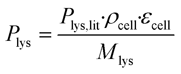
The coarse-grained colony volume model with adjusted diffusion was applied.42 This has been found to be a good approximation of the detailed geometry of a cell colony in such microfluidic growth chambers.42 In the model, the producer-side of the chamber is populated with a colony of C. glutamicum taking up glucose and producing L-lysine, whereas the consumer-side is left empty. The colony was described by a volume reaction rate, which distributes the sum of the uptake and production rates of all cells homogeneously over the volume taken up by the colony, within the entire producer-part of the chamber. As the cell membranes do not generally permit unhindered passage of larger molecules, the diffusion coefficients of glucose and L-lysine within this area were lowered to 36% of their values in water. The reduced diffusion coefficients as well as the glucose uptake and L-lysine production rates were calculated assuming that εcell = 47% of the chamber volume is taken up by cells, estimated according to image-based cell area determination of one exemplary chamber.
The molar L-lysine production rate was estimated according to eqn (1), where Plys,lit = 0.068 g gcdw−1 h−1 is the L-lysine production rate as reported by Buchholz et al.,47ρcell = 474 gcdw L−1 is the cell dry weight per cell volume according to Unthan et al.,38 and Mlys = 146.19 g mol−1 is the molecular weight of L-lysine.
 | (1) |
As a first estimate, the glucose uptake (0.29 mol m−3 s−1) was estimated by dividing the L-lysine production rate by the molar yield Yps = 0.1,47 which shows adequate agreement with the glucose uptake rate results for a similar strain variant reported by van Ooyen et al.48
Since this rate is based on measurements from very different conditions in shake flasks the model was also solved for a ten times higher uptake rate to provide a conservative scenario for the glucose concentration gradients.
The uptake and production rates were set constant, as the provided glucose concentration of 222 mmol L−1 is far in excess of the reported half-velocity constant for glucose of 4.5 mmol L−1.49 The computational geometry was discretized using rectangular elements within the growth chamber area and free tetrahedral meshing in the supply channels. A total of 823073 elements is used, and a mesh independence was verified using a finer mesh with 1600193 elements. Quadratic functions were used to calculate velocity profiles and concentrations and linear functions for the pressure.
Results and discussion
Device design and principle
The presented microfluidic device (Fig. 1A) was designed for cultivation and analysis of interactions between two different bacterial strains in monolayer growth chambers. One cultivation device holds 150 single chambers. The chambers are split into three independent arrays with adjacent supply channels on two chamber sides (Fig. 1B). One cultivation chamber incorporates two compartments that are spatially separated by a barrier structure with several nanochannels to keep both strains separated while allowing diffusion of metabolites from one chamber into the other (Fig. 1C). While the supply channels are 10 μm in height and 80 μm in width, the cultivation regions are approximately 1 μm high and cover an area of around 4800 μm2 each. This restricts cell growth to a monolayer, which enables single-cell resolution for image-based analysis and the cultivation of small microcolonies with hundreds of cells. The barrier structure in the center of the chamber includes nanochannels with a diameter of 600 nm (Fig. 1D). Due to the described dimensions, the flow inside the supply channels is laminar, and mass transfer in the cultivation regions is strongly dependent on diffusion during cultivation (colony growth or steady-state cultivation). At the initial growth phase (when chambers are seeded), flow experiments with fluorescent beads and CFD simulations have shown that there is a comparatively slow flow through the chambers (Fig. S2†). Flow velocity inside the supply channels is about 6 mm s−1 while velocities inside chambers range from 30 to 40 μm s−1 at the chamber entrance to 0 μm s−1 in the chamber center.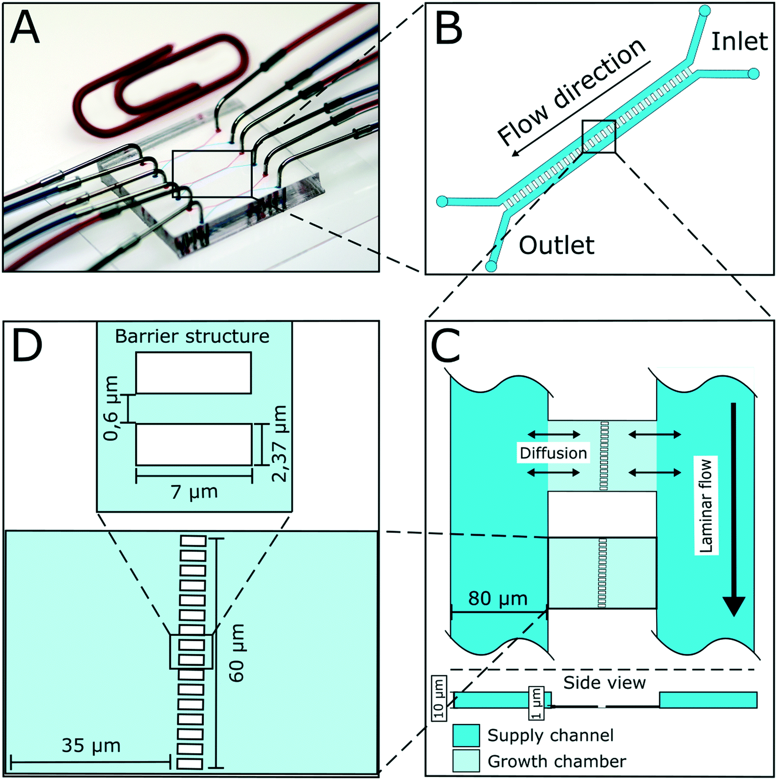 | ||
| Fig. 1 Design of microfluidic device for co-cultivation of bacterial strains. (A) Microfluidic chip setup with needles connected to inlets and outlets for medium supply. (B) Illustration of one chamber array. 50 cultivation chambers are arranged in parallel with supply channels on two sides. (C) Mass transport from main supply channels into the shallow chamber regions happens mainly via diffusion. Growth chambers have a height of approximately 1 μm, while supply channels have a height of 10 μm. (D) Growth chambers are separated by a barrier structure incorporating nanochannels with a diameter of 600 nm. | ||
Cell inoculation is a two-step process (Fig. 2). In the first step, the first strain is filled into the inlet of the supply channel at one side of the chamber array and the cells are randomly trapped in the cultivation regions (Fig. 2A). The cell suspension containing the second strain is injected into the other inlet and the opposite chamber sides are filled up with cells (Fig. 2B). Due to the shallow chamber height, the previously injected strain retains in the chamber and is not washed out with the injection of the second strain. After cell seeding, the inlets of the supply channels are connected to medium syringes and a continuous flow with a velocity of 200 nl min−1 is applied via a syringe pump. Cells are continuously supplied with fresh medium and can grow in their chamber compartments (Fig. 2C). Depending on the organism size, up to 900 ± 25 cells fit into one compartment (see Fig. S3†) until dividing cells are pushed outside the chamber into the supply channel. Inside the supply channel, cells are dragged with the medium flow towards the channel outlet, which allows a “steady-state” cultivation of the two separated cell populations over longer cultivation times.
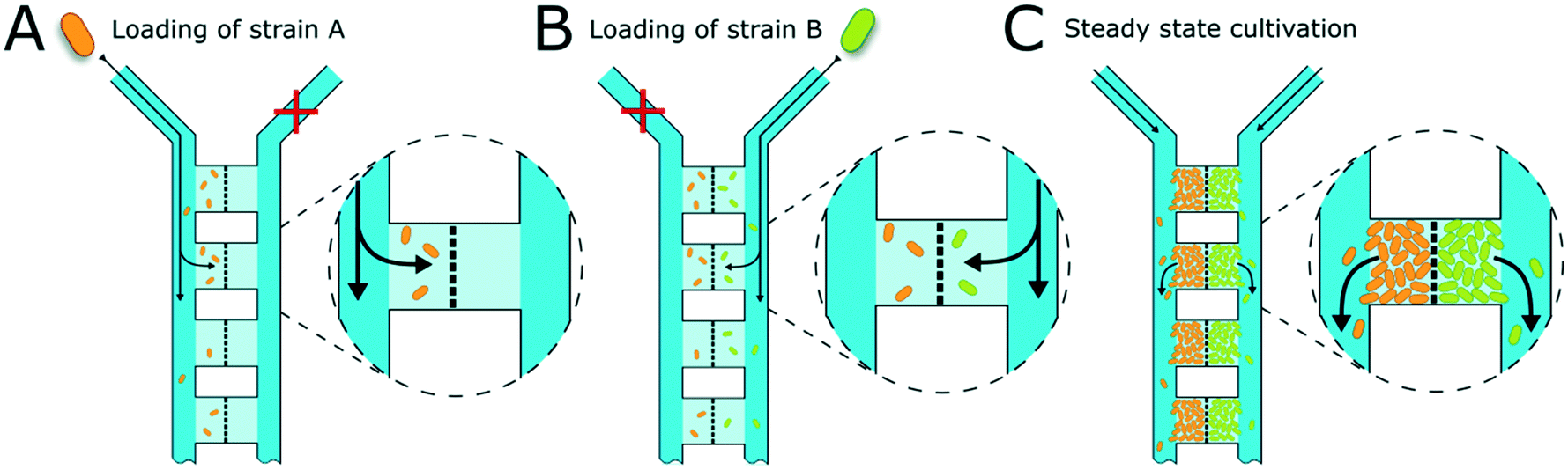 | ||
| Fig. 2 Illustration of chamber loading. (A) The first bacterial strain is injected into one supply channel on the inlet side. Cells are flushed through the supply channel towards the outlet and get randomly trapped inside the shallow cultivation areas. The barrier structure in the middle of the cultivation chambers restrains the cells. (B) The second bacterial strain is injected into the other inlet and cells get trapped in the chamber regions on the opposite side of the barrier structure. The first strain is not washed out during loading of the second strain due to the low chamber height, where cells are physically trapped (dimensions not to scale). (C) When cells have filled the chamber areas, dividing cells are washed away with the medium flow towards the outlet. A quasi steady-state cultivation is reached. | ||
Functionality of the device for co-cultivation
To demonstrate the functionality of the device, we have co-cultivated the L-lysine auxotrophic strain C. glutamicum ΔlysA pEKEX2-eYFP in combination with the L-lysine-producing strain C. glutamicum DM1800 (see Materials and methods). In a first step we added L-lysine to the medium for interaction-independent growth (Fig. 3). One strain was labelled with EYFP to make it distinguishable from the other. In the experiment shown, the exponential growth phase was followed by a 6 hour steady-state growth phase (from t = 12.5 h to t = 18 h) in which the cell number stayed constant over time. The cells were not able to pass the barrier structure in the chamber center for more than 6 h until the cultivation was stopped. The cell growth of the two C. glutamicum strains was determined, revealing average growth rates of μmax = 0.35 ± 0.02 h−1 (for C. glutamicum DM1800) and μmax = 0.29 ± 0.01 h−1 (for C. glutamicum ΔlysA pEKEX2-eYFP) during exponential growth (see the ESI† V1). The slower growth rate of C. glutamicum ΔlysA pEKEX2-eYFP is likely due to the additional plasmid burden for eYFP expression.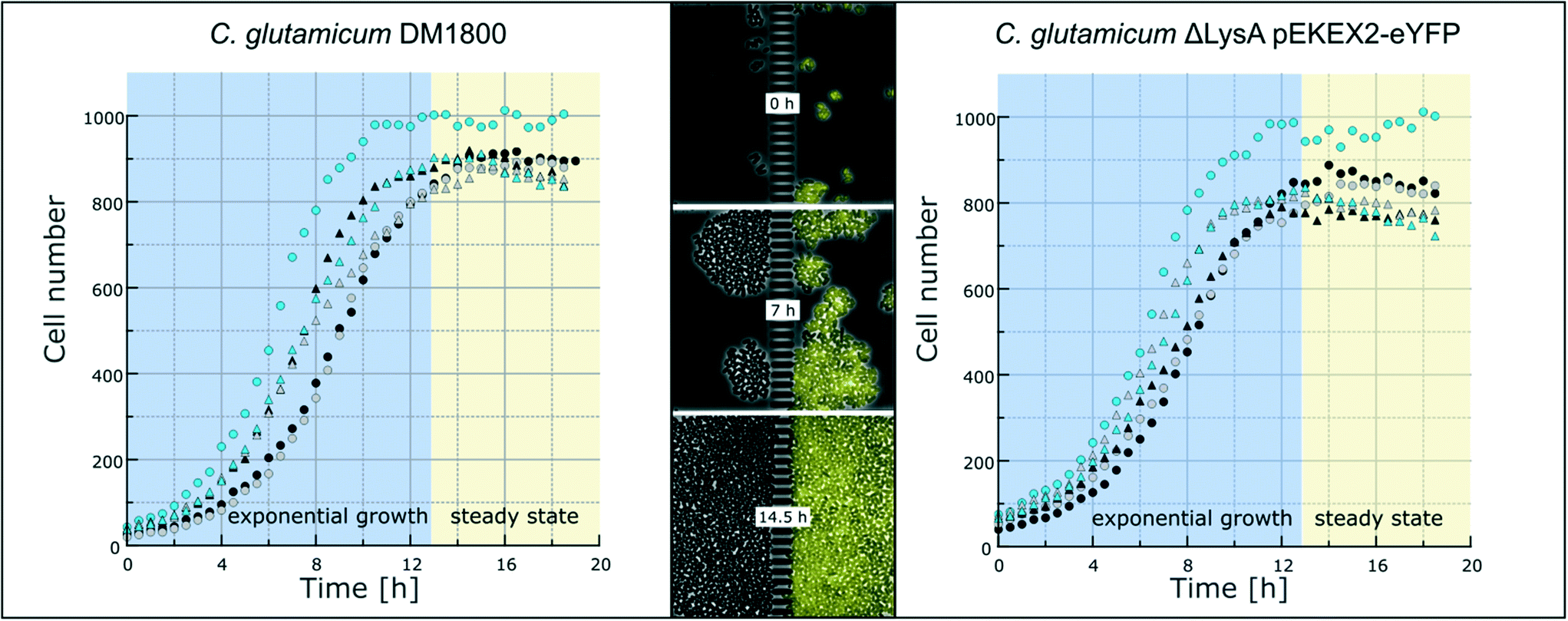 | ||
| Fig. 3 Growth of C. glutamicum. Growth curves of six individual colonies each of C. glutamicum DM1800 (left) and C. glutamicum ΔlysA pEKEX2-eYFP (right) in CGXII with 10 mmol L−1L-lysine. After approximately 12.5 h, cells have filled the growth chamber. Afterwards, steady-state growth can be followed. Selected chamber after 0, 7 and 14.5 hours of cultivation time (middle). | ||
In preliminary experiments different chamber dimensions (ranging from width × length = [60–120] μm × [30–70] μm) and geometries were tested and optimized regarding stability for long-term cultivation. Using larger growth chambers resulted in failure of the co-cultivation as cells built up too much pressure because of high cell densities on the barrier structure and were squeezed into the nanochannels (Fig. S4†). As a result, cells were passing the nanochannels and entering the connected chamber compartment of the second strain. A similar effect was already observed by Männik et al., who examined the cell growth of motile E. coli cells inside micro-channels with a diameter of 300 nm.50 The flexible cell shape of cells passing the nanochannels could be related to the thin cell wall of Gram-negative bacteria. In contrast to these studies, in which cell movement through microchannels was triggered by nutrient gradients, non-motile C. glutamicum cells in our case were able to pass the nanochannels solely because of pressure mediated by cell division. Even though these Gram-positive bacteria have a firmer cell wall, they were able to move inside our nanochannels by cell division driven by a pressure gradient within the inner part of the cultivation chamber. Additionally, cells near the nanochannels showed a change of morphology (Fig. S4A†) due to the resulting physical pressure. Because the chosen nanochannel diameter of 600 nm is near the fabrication limit of the photolithographic process (wavelength of photoresist UV radiation: 365 nm), the nanochannel diameter could not be further reduced to abolish cell migration between the cultivation chambers. Instead, the chamber length was reduced to 35 μm, which turned out to be the optimal length for stable long-term co-cultivation.
Despite the physical stability of the barrier structure, nutrient gradients inside the microfluidic growth chambers can affect cell growth. Simulations of nutrient distributions inside monolayer growth chambers showed that minor nutrient gradients towards the center of the chamber can occur.42
To further analyze whether a nutrient gradient can affect cell growth in the co-cultivation device presented here, we simulated the glucose distribution in a chamber filled with C. glutamicum DM1800 cells (Fig. S5†). The assumptions for this simulation are described in detail in the section “CFD simulations”. Compared to a glucose concentration of 222 mmol L−1 inside the supply channels, the lowest glucose concentration predicted in the middle of a colony is around 221.5 mmol L−1, and even 217 mmol L−1 for ten times higher uptake rates, as shown in Fig. S5.† Therefore, the glucose gradient is unlikely to impact the cells in the developed device.
Analysis of microbial interaction
The spatial separation of bacterial strains is, for some interaction studies, a prerequisite for the analysis of different microbial interactions. As a model system, we applied a synthetic microbial consortium with commensalistic interactions. The L-lysine auxotrophic strain C. glutamicum ΔlysA pEKEX2-eYFP was co-cultured with the L-lysine-producing strain C. glutamicum DM1800 in lysine-free medium for unidirectional growth dependency (Fig. 4A).51 In the first experiments, we investigated the microbial interactions in the previously developed monolayer growth chambers.25 Due to the unidirectional metabolic dependency, long-term investigations were not possible due to an overgrowth of the dominant strain (Fig. S1†). The lag-phase of the auxotrophic strain plays an important role in the overgrowth as there must be a certain amount of producer cells before L-lysine accumulation occurs in the growth chamber to initiate cell growth of the auxotrophic strain. This leads to rapid washing out of the auxotrophic strain before it starts to grow.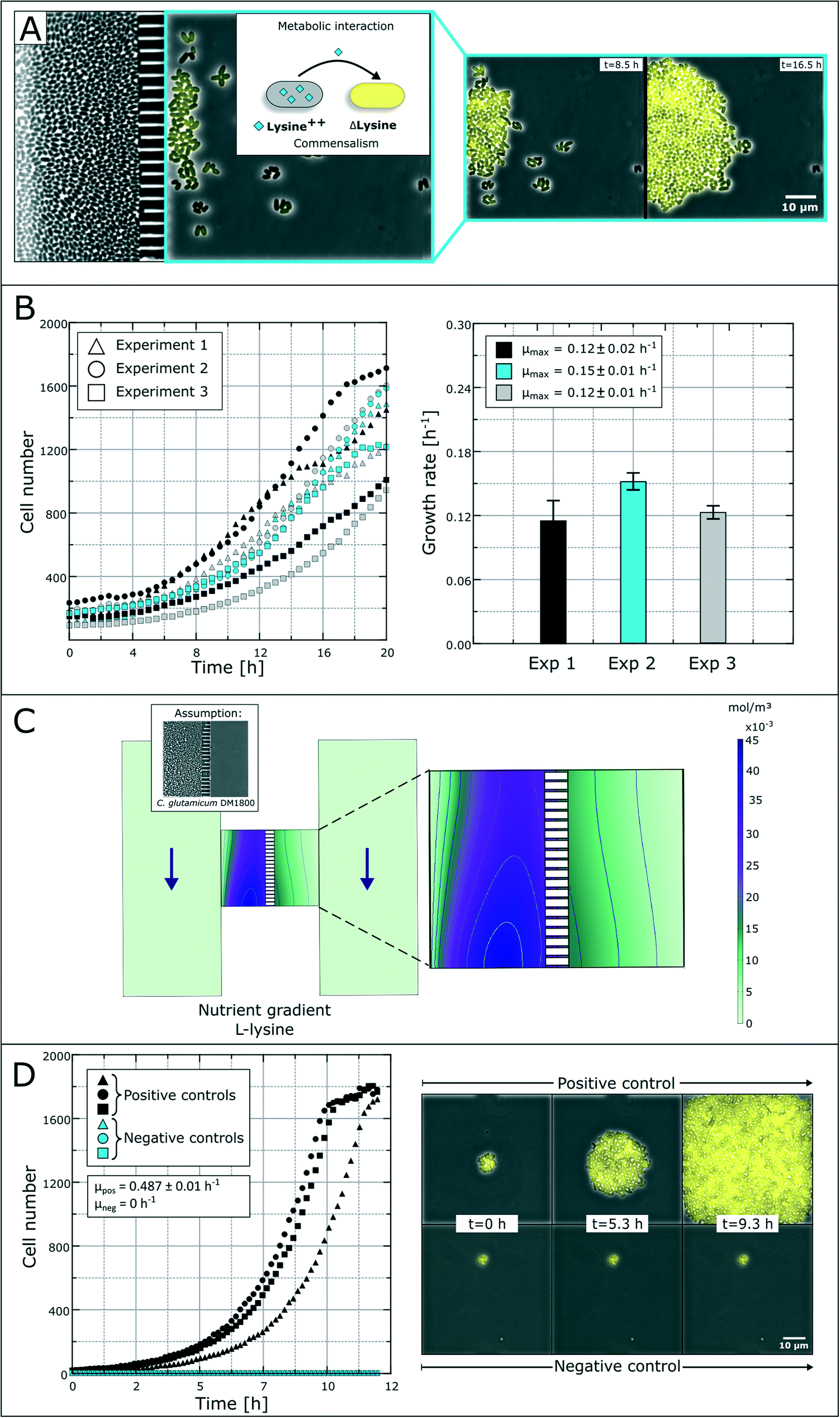 | ||
| Fig. 4 Study of bacterial commensalism. (A) Schematic overview and time-lapse images of commensalistic interaction between two C. glutamicum strains. Survival and growth of an eYFP-labeled L-lysine auxotrophic strain is dependent on the secreted L-lysine from a production strain. (B) Growth curves and growth rates of the L-lysine auxotrophic strain in co-cultivation with C. glutamicum DM1800 without additional L-lysine in the medium. (C) CFD simulation of the L-lysine gradient inside the growth chamber with the producing strain in the left compartment. (D) Colony growth curves of positive and negative control experiments with C. glutamicum ΔlysA PEKEX2-eYFP. The positive control was supplied with 10 mmol L−1L-lysine. | ||
Applying the above presented microfluidic device, we were able to cultivate and investigate the chosen model system and its interactions (Fig. 4B). The colonies of the ΔlysA strain in co-cultivation with the producer strain reached growth rates of μmax = 0.12 ± 0.02 h−1, μmax = 0.15 ± 0.01 h−1 and μmax = 0.12 ± 0.01 h−1 in three independent experiments. So far, auxotrophic cell growth could only be observed when the producer cells were present in a high cell number and the whole chamber compartment was covered with cells (see Fig. S3†). The varying growth curves (Fig. 4B) could be a result of heterogeneity in the L-lysine-producing colony as well as heterogeneity in L-lysine uptake in auxotrophic colonies and nutrient gradients within a colony.43 However, the results prove the unidirectional dependency in the here applied synthetic commensalistic community. Even though the exact amount of produced and consumed L-lysine cannot be measured, we aim for the indirect determination of the L-lysine concentration based on the growth rate of the cells. The feasibility of this approach is currently under investigation.
In an alternative approach to deduce L-lysine concentrations inside the chamber compartments we performed a CFD simulation. For the L-lysine gradient simulation, we assumed that one chamber compartment is filled with the producer strain C. glutamicum DM1800, while the other compartment is empty (Fig. 4C). In the simulation, the L-lysine concentration on the producer side reaches up to 45 μmol L−1, while the L-lysine concentration on the empty consumer-side reaches only 5–15 μmol L−1. If we assume unhindered diffusion of L-lysine through the cells the L-lysine concentration on the consumer-side drops roughly to 3–8 μmol L−1. Hence, a large amount of produced L-lysine is lost by diffusion into the supply channels, where all metabolites are washed out with the applied flow of fresh medium.
For further growth characterization, the auxotrophic strain was cultivated as a mono-culture with a surplus of L-lysine (10 mmol L−1) in defined medium as a positive control and without L-lysine as a negative control (Fig. 4D). The positive control shows a perfect exponential growth curve in L-lysine-rich medium with a growth rate of μ = 0.49 ± 0.01 h−1. After 11 hours the cell number reached a plateau due to limited chamber volume. The corresponding negative control resulted in an expected growth stagnation (see the ESI† V2).
The rather poor growth rate of the L-lysine auxotrophic strain in co-cultivation indicates that the producer strain C. glutamicum DM1800 did not produce enough L-lysine for maximal growth of the L-lysine auxotrophic strain, or the L-lysine exchange was hindered due to high cell densities and small exchange area via the nanochannels. According to the simulation results, a maximum of 15 μmol L−1L-lysine reaches the chamber compartment with the auxotrophic strain, when the producer side is filled with cells. This explains the reduced growth compared to the growth rate obtained with saturated L-lysine concentrations (10 mmol L−1 in positive control experiments).
These results show that the co-cultivation device is functional for interaction growth studies based on image analysis. Yet, further investigations concerning diffusion rates and uptake rates of metabolites are necessary to understand diffusion-based interaction in bacterial co-cultures in a full quantitative manner.
Contact-dependent cell–cell interaction
In contrast to secretion- and diffusion-based cell communication and interaction, cell–cell interactions may require direct cell contact. To study whether specific cell mechanisms are contact dependent or not, the represented co-cultivation device offers a method to rule out the necessity of direct cell contact. For this purpose, we chose bacterial conjugation that requires direct cell contact as an extensively studied mechanism52,53 of gene transfer between two cells. This process involves the unidirectional transfer of genetic material from the donor cell to the recipient cell initiated by connection via pili followed by direct cell contact. To our best knowledge, conjugation was not shown in dynamic live-cell imaging before. We performed a co-cultivation of strain P. putida KT2440 harboring the non-mobilizable plasmid pJT'Tmcs-mCherry and strain E. coli S17-1 containing the mobilizable vector pRhokHi-2-EYFP in our microfluidic co-cultivation devices, where direct cell contact is either inhibited or allowed. For conjugation, E. coli acts as the donor strain and P. putida is the recipient of genetic information from E. coli. Because of the respective expression plasmids, both strains constitutively express different fluorescent proteins resulting in green (EYFP expressing E. coli cells are colored green in all shown images for better visualization) or red (P. putida) fluorescing cells. A successful conjugation, in contrast, should lead to simultaneous expression of both fluorescent proteins in the recipient cell (Fig. 5A). According to this assumption, no yellow fluorescence should occur when cell contact is inhibited via spatially separated co-cultivation chambers, while direct cell contact should lead to a change of the fluorescence signal from red to yellow (Fig. 5B).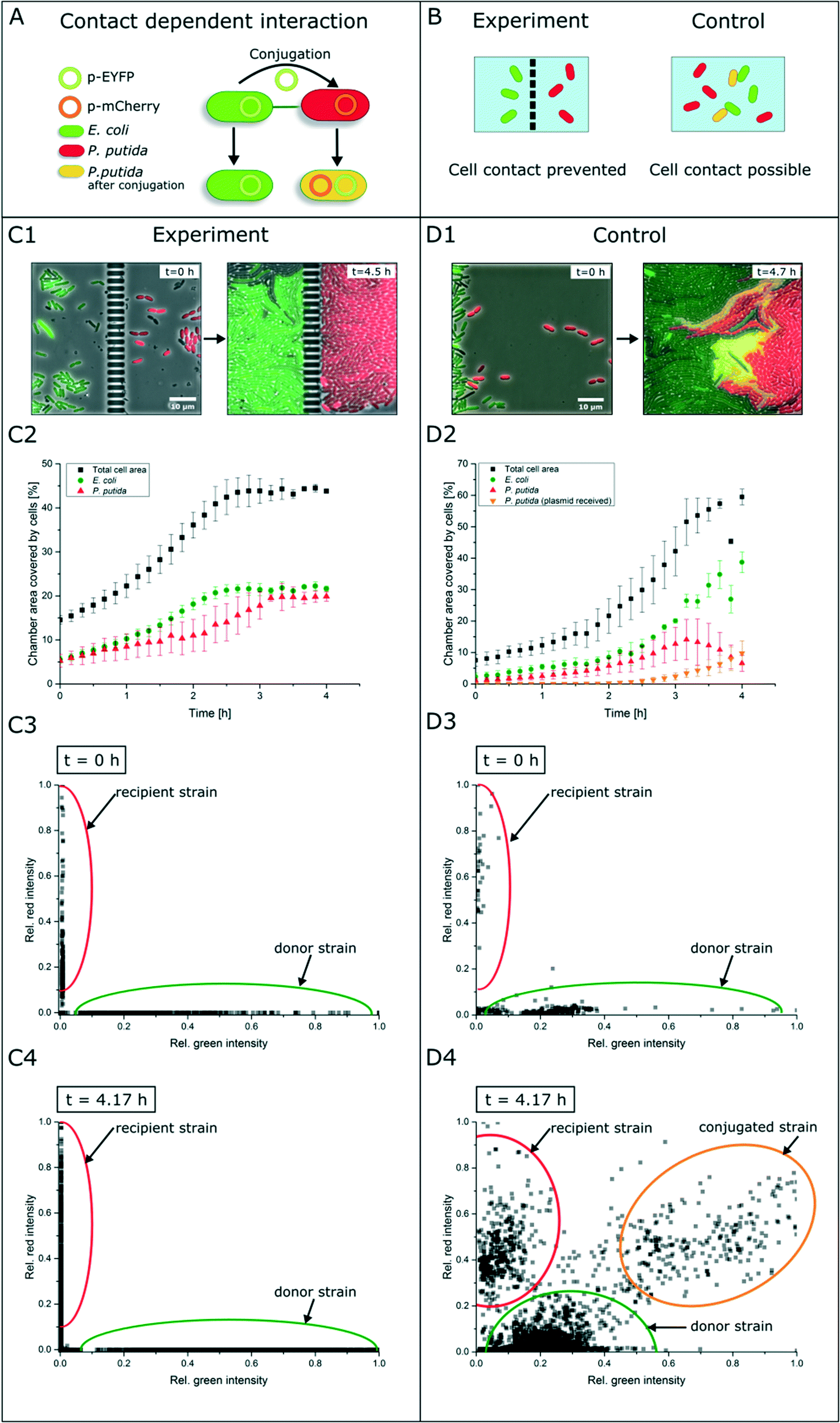 | ||
| Fig. 5 Study of contact-dependent interaction. (A) E. coli cells harboring an EYFP plasmid and P. putida cells containing an mCherry plasmid. E. coli donor cells can pass their plasmid via conjugation to P. putida cells. After successful conjugation, P. putida expresses both fluorescent proteins and an overlay of both colors occurs. (B) Working principle of experiment and control experiment with the aforementioned cells. When cells are cultured spatially separated, no fluorescence shift should appear, while direct cell contact should allow plasmid exchange. (C1 and C2) In microfluidic co-cultivation chambers no fluorescence shift to yellow could be observed. (C3 and C4) Relative fluorescence signals of each cell determined by image analysis. (D1 and D2) Relative fluorescence signals of each cell determined by image analysis. With direct cell contact an increase of yellow fluorescent cells was detected. (D3 and D4) Relative fluorescence signals of each cell within the control experiment determined by image analysis. | ||
Results show that inside the spatially separated growth chambers no change of the initial fluorescence signals was observed in P. putida cells (Fig. 5C1). Even after 4.5 h of cultivation, no conjugation events occurred. The observation of 30 chambers confirmed the findings (data not shown). Fig. 5C2 shows the growth curves of all cell types (red, green, yellow and total cell area) in three chambers. Red P. putida and green E. coli cells are growing in their chamber compartment, but no yellow cells appear during the cultivation time (see the ESI† V3). This was also confirmed by a measurement of the relative red and green fluorescence intensity at the start (t = 0 h) (Fig. 5C3) and end of cultivation (t = 4.17 h) (Fig. 5C4).
On the contrary, co-cultivation in a monolayer growth chamber without a physical barrier resulted in simultaneous expression of red and green fluorescent proteins in single P. putida cells that had direct cell contact to E. coli cells (Fig. 5D1, see the ESI† V4). E. coli cells maintained their EYFP fluorescence, which is also proof of unidirectional gene transfer. The conjugational gene transfer could also be identified as a very fast mechanism. P. putida started to express EYFP in some cases already 30 min after cell contact to E. coli. However, not all P. putida cells which had contact to E. coli cells showed a fluorescence shift. This could be due to shear forces during cell growth, which causes interruption of cell contact accompanied by termination of gene transfer. In general, the cell–cell connection during conjugation is very fragile and can easily be interrupted by shear forces.52 The growth curves in three chambers of all cell types revealed the appearance and increase of yellow cells after 2.5 h, while the red cell number is declining (Fig. 5D2). A subpopulation expressing nearly the same amount of yellow and red fluorescent proteins could also be shown following relative fluorescence measurements at t = 0 h and t = 4.17 h (Fig. 5D3 and D4).
We are currently investigating bacterial conjugation on the single-cell level in more detail. In particular, the influence of shear forces, medium composition and ratio of donor to acceptor cells is under closer investigation. Single-cell analysis may help to understand the external influences on bacterial conjugation to increase the efficiency and control of gene transfer in the future.
Conclusions
We developed and established a new microfluidic co-cultivation system for the analysis of a consortium of two bacterial strains with full spatio-temporal resolution of single cells. The system is characterized by fast exchange of metabolites due to short diffusion distances but concurrent physical separation of the strains. In comparison to previously reported systems, this allows for systematic studies of bacterial interactions with single-cell resolution. We showed on three examples the functionality of the device for the investigation of bacterial interaction modes. First, a long-term cultivation of two bacterial strains was performed to test the stable separation of both colonies. Second, a synthetic commensalistic consortium, consisting of an L-lysine producer and an L-lysine auxotrophic strain, was successfully co-cultivated. Finally, conjugation between E. coli and P. putida was analyzed as a contact-dependent interaction. Diffusive interactions as well as interactions based on direct cell-to-cell contact could be analyzed using our microfluidic co-cultivation device.For quantitative analysis and understanding of interactions, the system needs to be further characterized in terms of detailed CFD studies in order to optimize structure geometry and experimental settings. Hereby, the focus will be the optimization of the chamber shape to host a minimal amount of producer strain by optimal exchange of metabolites with the acceptor strain.
PDMS is the chosen prototyping material and has many advantages. It is easy to fabricate, transparent, and biocompatible and has good gas permeability. For commercial use, glass or thermoplasts such as PMMA or PC are more common.54,55 Liquid glass in combination with 3D printing shows a promising alternative to conventional microfluidic materials that combines all positive characteristics such as flexibility in fabrication, biocompatibility and chemical resistance regarding solvents.56
Analysis of the live-cell imaging data is currently performed by image analysis.57,58 Current algorithms and workflows are focusing on the analysis of single-strain data. Therefore, novel methods need to be developed for multi-strain image sequences. This lays the foundation for a better understanding of microbial interactions in nature as well as in synthetic communities.
Author contributions
Conceptualization and investigation: AB, FH, AL and AG. Formal analysis and validation: AB, FH, CW, YK and AG. Visualization: AB, CW and YK. Resources: FH, NT, TD, DK, EL, SN and AG. Supervision: AG. Writing: AB and AG.Conflicts of interest
There are no conflicts of interest to declare.Acknowledgements
This work was partly performed at the Helmholtz Nanoelectronic Facility (HNF) of Forschungszentrum Jülich GmbH.59 We thank Lothar Eggeling for providing the lysine auxotrophic C. glutamicum variant. Part of the work was funded by the Ministry of Culture and Science within the framework of the NRW-Strategieprojekt BioSC (No. 313/323-400-002 13). Moreover, the Helmholtz Association (PD-311 and VH-NG-1029) is gratefully acknowledged for funding.References
- S. Ghosh, R. Chowdhury and P. Bhattacharya, Appl. Microbiol. Biotechnol., 2016, 100, 4283–4295 CrossRef CAS PubMed.
- H. Fujita, S. Aoki and M. Kawaguchi, PLoS One, 2014, 9, e93670 CrossRef PubMed.
- E. J. Stewart, J. Bacteriol., 2012, 194, 4151–4160 CrossRef CAS PubMed.
- R. I. Amann, W. Ludwig, K. H. Schleifer, R. I. Amann and W. Ludwig, Microbiol. Rev., 1995, 59, 143–169 CAS.
- M. T. Mee, J. J. Collins, G. M. Church and H. H. Wang, Proc. Natl. Acad. Sci. U. S. A., 2014, 111, E2149–E2156 CrossRef CAS PubMed.
- M. Baumgart and S. Noack, Trends Biotechnol., 2018 DOI:10.1016/j.tibtech.2018.07.011 , accepted for publication.
- J. Bader, E. Mast-Gerlach, M. K. Popovic, R. Bajpai and U. Stahl, J. Appl. Microbiol., 2010, 109, 371–387 CrossRef CAS PubMed.
- H. C. Bernstein and R. P. Carlson, Comput. Struct. Biotechnol. J., 2012, 3, e201210017 CrossRef PubMed.
- N. Fu, P. Peiris, J. Markham and J. Bavor, Enzyme Microb. Technol., 2009, 45, 210–217 CrossRef CAS.
- A. A. Zeidan and E. W. J. Van Niel, Int. J. Hydrogen Energy, 2009, 34, 4524–4528 CrossRef CAS.
- S. Kurata, K. Yamada, K. Takatsu, S. Hanada, O. Koyama, T. Yokomaku, Y. Kamagata, T. Kanagawa and R. Kurane, Biosci., Biotechnol., Biochem., 2003, 67, 8–14 CrossRef CAS PubMed.
- K. Zhou, K. Qiao, S. Edgar and G. Stephanopoulos, Nat. Biotechnol., 2015, 33, 377–383 CrossRef CAS PubMed.
- K. Brenner, L. You and F. H. Arnold, Trends Biotechnol., 2008, 26, 483–489 CrossRef CAS PubMed.
- S. H. J. Chan, M. N. Simons and C. D. Maranas, PLoS Comput. Biol., 2017, 13, e1005539 CrossRef PubMed.
- T. S. Kaminski, O. Scheler and P. Garstecki, Lab Chip, 2016, 16, 2168–2187 RSC.
- J. Dai, S. H. Yoon, H. Y. Sim, Y. S. Yang, T. K. Oh, J. F. Kim and J. W. Hong, Anal. Chem., 2013, 85, 5892–5899 CrossRef CAS PubMed.
- J. P. Frimat, M. Becker, Y. Y. Chiang, U. Marggraf, D. Janasek, J. G. Hengstler, J. Franzke and J. West, Lab Chip, 2011, 11, 231–237 RSC.
- J. W. Hong, S. Song and J. H. Shin, Lab Chip, 2013, 13, 3033 RSC.
- J. Park, A. Kerner, M. A. Burns and X. N. Lin, PLoS One, 2011, 6, e17019 CrossRef CAS PubMed.
- H. J. Kim, J. Q. Boedicker, J. W. Choi and R. F. Ismagilov, Proc. Natl. Acad. Sci. U. S. A., 2008, 105, 18188–18193 CrossRef CAS PubMed.
- J. E. Keymer, P. Galajda, C. Muldoon, S. Park and R. H. Austin, Proc. Natl. Acad. Sci. U. S. A., 2006, 103, 17290–17295 CrossRef CAS PubMed.
- F. J. H. Hol, P. Galajda, K. Nagy, R. G. Woolthuis, C. Dekker and J. E. Keymer, PLoS One, 2013, 8, e77042 CrossRef CAS PubMed.
- K. Nagy, O. Sipos, É. Gombai, Á. Kerényi, S. Valkai, P. Ormos and P. Galajda, Chem. Biochem. Eng. Q., 2014, 28, 225–231 CrossRef CAS.
- J. R. Moffitt, J. B. Lee and P. Cluzel, Lab Chip, 2012, 12, 1487–1494 RSC.
- A. Grünberger, C. Probst, S. Helfrich, A. Nanda, B. Stute, W. Wiechert, E. von Lieres, K. Nöh, J. Frunzke and D. Kohlheyer, Cytometry, Part A, 2015, 87, 1101–1115 CrossRef PubMed.
- E. Hentschel, C. Will, N. Mustafi, A. Burkovski, N. Rehm and J. Frunzke, Microb. Biotechnol., 2013, 6, 196–201 CrossRef PubMed.
- M. Vrljic, W. Kronemeyer, H. Sahm and L. Eggeling, J. Bacteriol., 1995, 177, 4021–4027 CrossRef CAS PubMed.
- T. Georgi, D. Rittmann and V. F. Wendisch, Metab. Eng., 2005, 7, 291–301 CrossRef CAS PubMed.
- S. G. Grant, J. Jessee, F. R. Bloom and D. Hanahan, Proc. Natl. Acad. Sci. U. S. A., 1990, 87, 4645–4649 CrossRef CAS.
- D. Hanahan, J. Mol. Biol., 1983, 166, 557–580 CrossRef CAS PubMed.
- R. Simon, U. Priefer and A. Pühler, Bio/Technology, 1983, 1, 784–791 CrossRef CAS.
- M. M. Bagdasarian, R. Lurz, B. Rückert, F. C. Franklin, J. Frey and K. N. Timmis, Gene, 1981, 16, 237–247 CrossRef CAS PubMed.
- K. E. Nelson, C. Weinel, I. T. Paulsen, R. J. Dodson, H. Hilbert, V. A. P. Martins dos Santos, D. E. Fouts, S. R. Gill, M. Pop, M. Holmes, L. Brinkac, M. Beanan, R. T. DeBoy, S. Daugherty, J. Kolonay, R. Madupu, W. Nelson, O. White, J. Peterson, H. Khouri, I. Hance, P. Chris Lee, E. Holtzapple, D. Scanlan, K. Tran, A. Moazzez, T. Utterback, M. Rizzo, K. Lee, D. Kosack, D. Moestl, H. Wedler, J. Lauber, D. Stjepandic, J. Hoheisel, M. Straetz, S. Heim, C. Kiewitz, J. Eisen, K. N. Timmis, A. Düsterhöft, B. Tümmler and C. M. Fraser, Environ. Microbiol., 2002, 4, 799–808 CrossRef CAS PubMed.
- N. Katzke, S. Arvani, R. Bergmann, F. Circolone, A. Markert, V. Svensson, K. E. Jaeger, A. Heck and T. Drepper, Protein Expression Purif., 2010, 69, 137–146 CrossRef CAS PubMed.
- S. Verhoef, H. Ballerstedt, R. J. M. Volkers, J. H. De Winde and H. J. Ruijssenaars, Appl. Microbiol. Biotechnol., 2010, 87, 679–690 CrossRef CAS PubMed.
- J. Sambrook, E. F. Fritsch and T. Maniatis, Molecular cloning: a laboratory manual, Cold Spring Harbor Laboratory Press, New York, 2nd edn, 1989 CAS.
- Q. Tu, J. Yin, J. Fu, J. Herrmann, Y. Li, Y. Yin, A. F. Stewart, R. Müller and Y. Zhang, Sci. Rep., 2016, 6, 1–8 CrossRef PubMed.
- S. Unthan, A. Grünberger, J. van Ooyen, J. Gätgens, J. Heinrich, N. Paczia, W. Wiechert, D. Kohlheyer and S. Noack, Biotechnol. Bioeng., 2014, 111, 359–371 CrossRef CAS PubMed.
- A. Grünberger, C. Probst, A. Heyer, W. Wiechert, J. Frunzke and D. Kohlheyer, J. Visualized Exp., 2013, 50560 Search PubMed.
- A. Ducret, E. M. Quardokus and Y. V. Brun, Nat. Microbiol., 2016, 1(7), 16077 CrossRef CAS PubMed.
- J. Schindelin, I. Arganda-Carreras, E. Frise, V. Kaynig, M. Longair, T. Pietzsch, S. Preibisch, C. Rueden, S. Saalfeld, B. Schmid, J. Y. Tinevez, D. J. White, V. Hartenstein, K. Eliceiri, P. Tomancak and A. Cardona, Nat. Methods, 2012, 9, 676–682 CrossRef CAS PubMed.
- C. Westerwalbesloh, A. Grünberger, W. Wiechert, D. Kohlheyer and E. von Lieres, Microb. Biotechnol., 2017, 10, 845–857 CrossRef CAS PubMed.
- C. Westerwalbesloh, A. Grünberger, B. Stute, S. Weber, W. Wiechert, D. Kohlheyer and E. von Lieres, Lab Chip, 2015, 15, 4177–4186 RSC.
- J. F. Comesaña, J. J. Otero, E. García and A. Correa, J. Chem. Eng. Data, 2003, 48, 362–366 CrossRef.
- J. K. Gladden and M. Dole, J. Am. Chem. Soc., 1953, 75, 3900–3904 CrossRef CAS.
- M. Melia Rodrigo, A. J. M. Valente, M. C. F. Barros, L. M. P. Verissimo, C. Romero, M. A. Esteso and A. C. F. Ribeiro, J. Chem. Thermodyn., 2014, 74, 227–230 CrossRef CAS.
- J. Buchholz, A. Schwentner, B. Brunnenkan, C. Gabris, S. Grimm, R. Gerstmeir, R. Takors, B. J. Eikmanns and B. Blombacha, Appl. Environ. Microbiol., 2013, 79, 5566–5575 CrossRef CAS PubMed.
- J. van Ooyen, S. Noack, M. Bott, A. Reth and L. Eggeling, Biotechnol. Bioeng., 2012, 109, 2070–2081 CrossRef CAS PubMed.
- V. F. Wendisch, A. A. De Graaf, H. Sahm and B. J. Eikmanns, J. Bacteriol., 2000, 182, 3088–3096 CrossRef CAS PubMed.
- J. Männik, R. Driessen, P. Galajda, J. E. Keymer and C. Dekker, Proc. Natl. Acad. Sci. U. S. A., 2009, 106, 14861–14866 CrossRef PubMed.
- M. Cavaliere, S. Feng, O. S. Soyer and J. I. Jiménez, Environ. Microbiol., 2017, 19, 2949–2963 CrossRef PubMed.
- A. J. F. Griffiths, W. M. Gelbart, J. H. Miller and R. C. Lewontin, in Modern Genetic Analysis, W. H. Freeman, New York, 1999 Search PubMed.
- Y. V. Nancharaiah, P. Wattiau, S. Wuertz, S. Bathe, S. V. Mohan, P. A. Wilderer and M. Hausner, Society, 2003, 69, 4846–4852 CAS.
- C. Matellan and A. E. Del Río Hernández, Sci. Rep., 2018, 8, 1–13 CrossRef PubMed.
- C. Iliescu, H. Taylor, M. Avram, J. Miao and S. Franssila, Biomicrofluidics, 2012, 6, 1–16 CrossRef PubMed.
- F. Kotz, K. Plewa, W. Bauer, N. Schneider, N. Keller, T. Nargang, D. Helmer, K. Sachsenheimer, M. Schäfer, M. Worgull, C. Greiner, C. Richter and B. E. Rapp, Adv. Mater., 2016, 4646–4650 CrossRef CAS PubMed.
- A. D. Balomenos, P. Tsakanikas, Z. Aspridou, A. P. Tampakaki, K. P. Koutsoumanis and E. S. Manolakos, BMC Syst. Biol., 2017, 11, 1–21 CrossRef PubMed.
- T. A. Nketia, H. Sailem, G. Rohde, R. Machiraju and J. Rittscher, Methods, 2017, 115, 65–79 CrossRef CAS PubMed.
- W. Albrecht, J. Moers and B. Hermanns, Journal of Large-Scale Research Facilities, 2017, 3, A112 CrossRef.
Footnote |
| † Electronic supplementary information (ESI) available. See DOI: 10.1039/c8lc00977e |
| This journal is © The Royal Society of Chemistry 2019 |