Hydrogen evolution with nanoengineered ZnO interfaces decorated using a beetroot extract and a hydrogenase mimic†
M. V.
Pavliuk
a,
A. M.
Cieślak
b,
M.
Abdellah
ae,
A.
Budinská
a,
S.
Pullen
a,
K.
Sokołowski
b,
D. L. A.
Fernandes
a,
J.
Szlachetko
b,
E. L.
Bastos
c,
S.
Ott
a,
L.
Hammarström
a,
T.
Edvinsson
 a,
J.
Lewiński
*bd and
J.
Sá
 *ab
*ab
aDepartment of Chemistry, Ångström Laboratory, Uppsala University, Uppsala, 75120, Sweden. E-mail: jacinto.sa@kemi.uu.se
bInstitute of Physical Chemistry, Polish Academy of Sciences, Warsaw, 01-224, Poland. E-mail: lewin@ch.pw.edu.pl
cDepartment of Fundamental Chemistry, Institute of Chemistry, University of São Paulo, 05508-000 São Paulo, Brazil
dFaculty of Chemistry, Warsaw University of Technology, Warsaw, 00-661, Poland
eDepartment of Chemistry, Qena Faculty of Science, South Valley University, 83523 Qena, Egypt
First published on 9th January 2017
Abstract
Herein, we report a nano-hybrid photo-system based on abundant elements for H2 production with visible light. The photo-system's proficiency relates to the novel ZnO nanocrystals employed. The ZnO carboxylate oligoethylene glycol shell enhances charge separation and accumulates reactive electrons for the photocatalytic process.
Hydrogen is believed to be among the top long-term solutions for renewable energy1 since its combustion is environmentally friendly, i.e., deprived of greenhouse gas emissions. However, current H2 production is not environmentally benign because it is based on fossil fuels. Thus, there are considerable efforts towards developing a widely available green process for its generation. In this context, solar photochemical proton reduction has emerged as an attractive route for large-scale hydrogen production, a part of the artificial photosynthesis concept.
Conceptually, artificial photosynthesis has the capacity to store solar energy in the form of chemical bonds,2 and can be attained by a plethora of ideas and strategies.3 The combination of molecular sensitizers, capable of absorbing solar light, with molecular proton reduction catalysts has emerged as a promising strategy for H2 evolution.4 The use of molecular components provides unmatchable flexibility and tunability with respect to the system design and synthesis, and clear spectroscopic fingerprints of intermediates in the photocatalytic cycle that can help the rational design of high performance solar fuel systems. Additionally, the system complies with the emergent research field dedicated to H2 generation without noble metals.5
The process of converting light energy into chemical bonds is connected to a multitude of sequential processes starting with photon absorption, which creates the charge separation state, followed by transport and accumulation of the generated charge carriers, culminating in the catalytic reaction.6 Revealing the system's weak points requires an understanding of each individual process and its relation to the others, which is often a daunting task but necessary to improve the overall efficiency of the system.6d There are several striking challenges crucial for the design of a photo-system, but two of them seem to be the hardest to attain (i) conciliation of the lifetimes of different processes and (ii) accumulation of equal charge at the active site. The former demands conciliation between charge generation lifetimes, typically below tens of ps, with typical catalytic reaction times occurring on a super-millisecond timescale. The latter entails storage of equally charged particles in or in close proximity to the active site since H2 evolution is a 2-electron process. This process has been recently labelled as accumulative charge separation.7
A popular strategy to mitigate the enumerated challenges is to link both the sensitizer and the catalyst to a semiconductor. The ideal semiconductor should have a large band gap with a conduction band edge having sufficient redox potential to reduce protons,8 be soluble and stable in aqueous media, and cost-effective. Commonly, TiO2 has been the preferred system.6b Employing ZnO is equally eligible,6b however, its amphoteric nature creates challenges with its usage in aqueous media.9 Still, this strategy only managed to extend the electron lifetime to the sub-ms timescale, partially due to the unwanted electron recombination with the oxidized photosensitizer motivated by the positive surface potential created after electron injection.10
Recently, we reported ultra-stable ZnO nanocrystals (NCs) modified with a carboxylate oligoethylene glycol shell (OEG-carboxylate) system soluble in aqueous media.11 Furthermore, an appropriate modification of the NCs' inorganic core–organic interface extended the electron's lifetime in the conduction band up to seconds,11 which is several orders of magnitude longer from what has been observed for other zinc oxide nanostructures.12 These unique properties open prospects for both photovoltaic and photocatalytic applications. Notably, the inorganic core–organic ligand interface possesses vacant-spots enabling further sensitization with a dye and/or the addition of a catalyst.11
In this study, we took advantage of the exceptional properties of ZnO–OEG NCs and created a nano-hybrid system for H2 evolution under visible light irradiation, schematically depicted in Scheme 1. The light-harvesting process was carried out by using a natural pigment obtained from beetroot (betanin), capable of injecting up to two electrons per photon absorbed13 into the ZnO conduction band in less than 15 ps.11 As an H2 evolving catalyst, we opted for the [FeFe(mcbdt)(CO)6] (mcbdt = 3-carboxybenzene-1,2-dithiolate)14 catalyst, a molecular mimic of [FeFe]-hydrogenase active sites.15 The molecular components (betanin [B] and catalyst [Cat]) are strongly anchored to the ZnO NC surface via the corresponding carboxylate groups. The presence of betanin and catalyst molecules within the ZnO–OEG NC shell and their interactions with ZnO surfaces were verified by UV-vis measurements (Fig. S1†). Fourier-transformed infrared (FTIR) analysis of the [FeFe(mcbdt)(CO)6] upon linkage shows no change in the carbonyl bands (Fig. S2†), suggesting that the linkage does not significantly affect the catalyst's molecular and electronic structure. UV-vis and FTIR analyses of the remaining solution show no traces of the unbounded catalyst. Thus, the complete linkage occurred via the carboxylate group of the benzoic ring. Furthermore, the PXRD and HRTEM measurements indicated that the size and crystallinity of the inorganic core of ZnO NCs was unaffected by the applied functionalization strategy (6.5 ± 0.4 nm before and 6.9 ± 0.5 nm after functionalization; Fig. S3 and S5†). The average hydrodynamic diameter of the resulting nano-hybrid ZnO–OEG–B–Cat NCs increased upon modification with betanin and the catalyst (13 ± 2 nm) in comparison to the unmodified ZnO–OEG NCs (7 ± 2 nm Fig. S4†). While some degree of aggregation cannot be completely discarded, the homogeneous size distribution after modifications (Fig. S4†) favours the hydrodynamic size increase due to the catalyst and sensitizer addition.
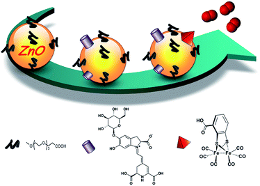 | ||
| Scheme 1 Schematic representation of ZnO–OEG NC functionalization with betanin (purple cylinder) and the [FeFe(mcbdt)(CO)6] catalyst (red pyramid). | ||
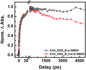
Ultrafast transient mid-infrared absorption spectroscopy measurements were performed to confirm the electronic connection between the sensitizer and the catalyst modulated by the semiconductor (Fig. 1). Infrared spectroscopy is a suitable technique because it provides direct detection of electrons in the semiconductor and their lifetime deprived of spectral artefacts. Electrons in the conduction band yield strong and broad absorption across the entire infrared domain resulting from the quasi-metal state formed upon electron injection.16
Previously, it was shown that betanin electron injection into ZnO–OEG occurs at two distinct times (1.3 and 14.0 ps)11 upon excitation at 532 nm. The addition of the catalyst did not significantly change the injection times (3 and 20 ps), which suggests that catalyst addition did not affect ZnO sensitization (Fig. 1). We have also shown that the signal for the ZnO–OEG–B system does not decay within the experimental delay line (ca. 5 ns).11 In contrast, the presence of the molecular catalyst led to an almost immediate drop in infrared absorption after electron injection, indicative of fast and effective electron transfer from the ZnO–OEG–B to the catalyst. It should be mentioned that the presence of the catalyst did not significantly affect the number of injected electrons.
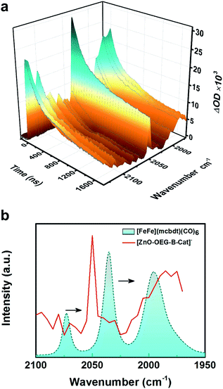
The experiments were extended into the microsecond time domain to monitor the metal carbonyl region (Fig. 2a). The experiments were carried out by nanosecond flash-quench measurements with IR detection and the data generated point by point from single-wavenumber kinetic traces that were averages of single flash experiments. The difference in spectra reveals the formation of two new peaks at 2050 and 1985 cm−1. The bleaches of three initial νC–O peaks were less visible due to the shift in the background signal resulting from electrons in the ZnO conduction band. The new peaks are red shifted with respect to the initial Fe2(I,I) state (2074 and 2036 cm−1) signal by 25–50 cm−1 (see Fig. 2b) suggestive of singly reduced catalyst species, which is in good agreement with both the theoretical IR spectra derived from geometry-optimized DFT calculations in the presence of the solvent (SI) and experimental νC–O shifts generated upon single reduction of the similar catalyst [FeFe(bdt)(CO)6] (bdt = benzenedithiolate) determined by transient absorption after a laser flash-quench cycle with one-electron reductants.17
There have been attempts to identify the structure of the singly reduced species. Felton et al.18 proposed a bridging coordination of a CO ligand upon 1e− reduction of [FeFe(bdt)(CO)6] as the stable singly reduced species. Mirmohades et al.17 suggested that such bridging CO should yield a new νC–O mode located at 1791 cm−1, which was not observed in the infrared spectrum of photoinduced [FeFe(bdt)(CO)6]−. Thus, an alternative geometry for the 1e− reduced complex with one largely elongated Fe–S bond, another broken Fe–S bond and an all-terminal coordination of the CO ligands was proposed, which is consistent with the calculations presented herein. The reasoning was based on calculations in the gas phase where our calculations using a self-consistent reaction field and the polarizable continuum model corresponding to DMSO show that bridge νC–O mode appears at 1691 cm−1 [Table S2†] for the single reduced state; using a solvent corrected model bridge νC–O could possibly be seen as the 1682 cm−1 mode reported by the same group, but was seen there for the doubly reduced state.
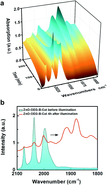
Due to the limitations of flash-quench measurements with the IR detection system (narrow range of energies probed and the short delay line), further measurements were carried out using steady-state FTIR measurements during the illumination of ZnO–OEG–B–Cat (acquisition rate 5 minutes per spectrum). Fig. 3a depicts the obtained 3D surface plot of IR transient absorption spectra upon excitation at 532 nm. During the 240 min illumination, the three initial νC–O bands (2074, 2036, and 1995 cm−1) almost vanish and five new absorption bands of the photo-reduced product at 2000, 1974, 1914, 1880, and 1825 cm−1 arise (Fig. 3a). The appearance of additional bands upon sustained illumination is related to the lower symmetry and/or protonation of the reduced catalyst ([FeFe(mcbdt)(CO)6]2−) compared to the original complex [FeFe(mcbdt)(CO)6]. Kinetic traces of two isolated νC–O bands related to the unreduced (2036 cm−1) and doubly reduced (1880 cm−1) catalyst depicted in Fig. S8† show a clear antagonistic behaviour suggestive of the concomitant depletion of the unreduced catalyst and formation of the doubly reduced catalyst via a comparatively short-lived singly reduced species. Note that the potentials for the [FeFe(bdt)(CO)6] first and second reductions are inverted so that the singly reduced species is expected to be unstable towards disproportionation.18 The photoreduction shift of the νC–O bands by ca. 160 cm−1 is consistent with the observed shift of [FeFe(bdt)(CO)6]2− (130 cm−1) generated electrochemically by Mirmohades et al.17 The 30 cm−1 variance relates to the solvent effects, which changes the bond length (Table S1†) and consequently the vibration.
The photocatalytic production of H2 was evaluated using an in-house purposely-built flow photo-reactor with a CW laser (532 nm) and quadrupole mass-spectrometer, as gas product detection.19 The use of monochromatic light enables precise betanin excitation19 and suppresses unwanted reactions with other photons that can damage the catalyst.19,20 (NH4)2[Co(H2O)5(β-HAla)]2[V10O28]·4H2O (β-HAla = β-alanine, +NH3–CH2–CH2–COO−) was used in a large excess21 as an irreversible donor. The decision to use the complex instead of more commonly used electron donors was done to prevent ligand exchange with the surface constituents (betanin, catalyst, and OEG).
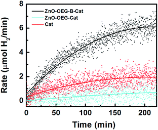
Fig. 4 shows hydrogen evolution of our photo-system, which is clearly superior with respect to the reference measurements. The amount of photo-generated H2 after 4 h on stream was roughly 976 μmol, equating to a turnover number of 11, which confirms that it is a true photocatalytic process. The photocatalytic system is relatively stable since after 6 h of photocatalysis followed by a dark period of 12 h, the FTIR spectrum of the initial [FeFe(mcbdt)(CO)6] state recovered to >95% (Fig. S9†). Moreover, a second cycle of photocatalysis performed with the same system yielded an additional 689 μmol of H2 in 4 h. It is worth mentioning that in both reaction cycles, the system takes roughly 200 min to reach a constant hydrogen production level, which is assumed to be the time necessary to reach steady-state conditions. This is the similar timeframe at which the complete reduction of the catalyst was observed with infrared (Fig. 3). Note that the molecular catalyst is known to deactivate in less than 2 h.19 It should be mentioned that the irreversible electron donor and proton donor are essential for H2 evolution.
In summary, we report a novel nano-hybrid photo-system for H2 evolution based on abundant materials. The system’s photocatalytic proficiency is intimately connected to the ZnO–OEG ability to attain accumulative charge separation, which mitigates the difference in time between charge generation and their catalytic use, and the high storage capacity of electrons. The ZnO–OEG system acts as an effective scaffold for the sensitizer and molecular catalyst, prolonging stability.
Acknowledgements
The authors would like to thank Uppsala University and The Knut and Alice Wallenberg Foundation for financial support. A. M. Cieślak, K. Sokołowski and J. Lewiński acknowledge the financial support from the National Science Centre, Poland (grants no. 2015/17/N/ST5/03333 and OPUS 2014/13/B/ST5/04420). J. Sá acknowledges the Swedish Research Council (VR grant no. 2015-03764), STINT (grant no. IB2015-6474) for the financial support.Notes and references
- (a) M. Z. Jacobson, W. G. Colella and D. M. Golden, Science, 2005, 308, 1901–1905 CrossRef CAS PubMed; (b) J. A. Turner, Science, 2004, 305, 972–974 CrossRef CAS PubMed.
- A. J. Bard and M. A. Fox, Acc. Chem. Res., 1995, 28, 141–145 CrossRef CAS.
- (a) A. Fujishima and K. Honda, Nature, 1972, 238, 37–38 CrossRef CAS PubMed; (b) Y. Tachibana, L. Vayssieres and J. R. Durrant, Nat. Photonics, 2012, 6, 511–518 CrossRef CAS; (c) R. Brimblecombe, A. Koo, G. C. Dismukes, G. F. Swiegers and L. Spiccia, J. Am. Chem. Soc., 2010, 132, 2892–2894 CrossRef CAS PubMed; (d) E. A. Ermilov, J.-Y. Liu, R. Menting, Y.-S. Huang, B. Rödera and D. K. P. Ng, Phys. Chem. Chem. Phys., 2016, 18, 10964–10975 RSC; (e) L. Sun, L. Hammarström, B. Åkermarka and S. Styring, Chem. Soc. Rev., 2001, 30, 36–49 RSC; (f) R. Abe, J. Photochem. Photobiol., C, 2010, 11, 179–209 CrossRef CAS.
- (a) T. Lazarides, T. McCormick, P. Du, G. Luo, B. Lindley and R. Eisenberg, J. Am. Chem. Soc., 2009, 131, 9192–9194 CrossRef CAS PubMed; (b) X. Li, M. Wang, D. Zheng, K. Han, J. Donga and L. Sun, Energy Environ. Sci., 2012, 5, 8220–8224 RSC; (c) Y. Peng, L. Shang, Y. Cao, G. I. N. Waterhouse, C. Zhou, T. Bian, L.-Z. Wu, C.-H. Tung and T. Zhang, Chem. Commun., 2015, 51, 12556–12559 RSC.
- M. Yin, S. Ma, C. Wu and Y. Fan, RSC Adv., 2015, 5, 1852–1858 RSC.
- (a) O. Bräm, A. Cannizzo and M. Chergui, Phys. Chem. Chem. Phys., 2012, 14, 7934–7937 RSC; (b) A. Hagfeldt and M. Grätzel, Chem. Rev., 1995, 95, 49–68 CrossRef CAS; (c) F. E. Osterloh, Chem. Mater., 2008, 20, 35–54 CrossRef CAS; (d) A. Heller, Science, 1984, 223, 1141–1148 CAS.
- (a) L. Hammarström, Acc. Chem. Res., 2015, 48, 840–850 CrossRef PubMed; (b) D. L. Ashford, M. K. Gish, A. K. Vannucci, M. K. Brennaman, J. L. Templeton, J. M. Papanikolas and T. J. Meyer, Chem. Rev., 2015, 115, 13006–13049 CrossRef CAS PubMed.
- G. Colon, Appl. Catal., A, 2016, 518, 48–59 CrossRef CAS.
- Y.-J. Yuan, J.-R. Tu, Z.-J. Ye, H.-W. Lu, Z.-G. Ji, B. Hu, Y.-H. Li, D.-P. Cao, Z.-T. Yu and Z. G. Zou, Dyes Pigm., 2015, 123, 285–292 CrossRef CAS.
- P. Friedli, H. Sigg and J. Sá, Photochem. Photobiol. Sci., 2014, 13, 1393–1396 CAS.
- A. M. Cieślak, M. V. Pavliuk, L. D'Amario, M. Abdellah, K. Sokołowski, U. Rybinska, D. L. A. Fernandes, M. K. Leszczyński, F. Mamedov, A. M. El-Zhory, J. Föhlinger, A. Budinská, M. Wolska-Pietkiewicz, L. Hammarström, J. Lewiński and J. Sá, Nano Energy, 2016, 30, 187–192 CrossRef.
- (a) T. J. Jacobsson, S. Viarbitskaya, E. Mukhtar and T. Edvinsson, Phys. Chem. Chem. Phys., 2014, 16, 13849–13857 RSC; (b) Y. Zhong, A. B. Djurišić, Y. F. Hsu, K. S. Wong, G. Brauer, C. C. Ling and W. K. Chan, J. Phys. Chem. C, 2008, 112, 16286–16295 CrossRef CAS; (c) L. Spanhel and M. A. Anderson, J. Am. Chem. Soc., 1991, 113, 2826–2833 CrossRef CAS; (d) E. A. Meulenkamp, J. Phys. Chem. B, 1998, 102, 5566–5572 CrossRef CAS.
- F. J. Knorr, J. L. McHale, A. E. Clark, A. Marchioro and J.-E. Moser, J. Phys. Chem. C, 2015, 119, 19030–19041 CAS.
- (a) S. Pullen, H. Fei, A. Orthaber, S. M. Cohen and S. Ott, J. Am. Chem. Soc., 2013, 135, 16997–17003 CrossRef CAS PubMed; (b) A. M. Brown, L. J. Antila, M. Mirmohades, S. Pullen, S. Ott and L. Hammarström, J. Am. Chem. Soc., 2016, 138, 8060–8063 CrossRef CAS PubMed.
- (a) R. Cammack, Nature, 1999, 397, 214–215 CrossRef CAS PubMed; (b) W. Lubitz, H. Ogata, O. Rîdiger and E. Reijerse, Chem. Rev., 2014, 114, 4081–4148 CrossRef CAS PubMed.
- L. J. Antila, F. G. Santomauro, L. Hammarström, D. L. A. Fernandes and J. Sá, Chem. Commun., 2015, 51, 10914–10916 RSC.
- M. Mirmohades, S. Pullen, M. Stein, S. Maji, S. Ott, L. Hammarström and R. Lomoth, J. Am. Chem. Soc., 2014, 136, 17366–17369 CrossRef CAS PubMed.
- G. A. N. Felton, A. K. Vannucci, J. Chen, L. T. Lockett, N. Okumura, B. J. Petro, U. I. Zakai, D. H. Evans, R. S. Glass and D. L. Lichtenberger, J. Am. Chem. Soc., 2007, 129, 12521–12530 CrossRef CAS PubMed.
- D. L. A. Fernandes, A. Budinská, M. V. Pavliuk and J. Sá, J. Photochem. Photobiol., A, 2017, 335, 36–39 CrossRef CAS.
- D. Streich, Y. Astuti, M. orlandi, L. Schwartz, R. Lomoth, L. Hammarström and S. Ott, Chem.–Eur. J., 2010, 16, 60–63 CrossRef CAS PubMed.
- M. V. Pavliuk, E. Mijangos, V. G. Makhankova, V. N. Kokozay, S. Pullen, J. Liu, J. Zhu, S. Styring and A. Thapper, ChemSusChem, 2016, 9, 2957–2966 CrossRef CAS PubMed.
Footnote |
| † Electronic supplementary information (ESI) available. See DOI: 10.1039/c6se00066e |
| This journal is © The Royal Society of Chemistry 2017 |

