
VO2 nanoflake arrays for supercapacitor and Li-ion battery electrodes: performance enhancement by hydrogen molybdenum bronze as an efficient shell material†
Xinhui
Xia‡
a,
Dongliang
Chao‡
a,
Chin Fan
Ng
a,
Jianyi
Lin
c,
Zhanxi
Fan
b,
Hua
Zhang
b,
Ze Xiang
Shen
*a and
Hong Jin
Fan
*a
aDivision of Physics and Applied Physics, School of Physical and Mathematical Sciences, Nanyang Technological University, 637371, Singapore. E-mail: fanhj@ntu.edu.sg; zexiang@ntu.edu.sg
bSchool of Materials Science and Engineering, Nanyang Technological University, 639798, Singapore
cEnergy Research Institute@NTU, Nanyang Technological University, Singapore 639798
First published on 21st November 2014
Abstract
Hydrogen molybdenum bronze (HMB) is electrochemically deposited as a homogeneous shell on VO2 nanoflakes grown on graphene foam (GF), forming a GF + VO2/HMB integrated electrode structure. Asymmetric supercapacitors based on the GF + VO2/HMB cathode and neutral electrolyte are assembled and show enhanced performance with weaker polarization, higher specific capacitance and better cycling life than the unmodified GF + VO2 electrode. Capacitances of 485 F g−1 (2 A g−1) and 306 F g−1 (32 A g−1) are obtained because of the exceptional 3D porous architecture and conductive network. In addition, the GF + VO2/HMB electrodes are also characterized as the cathode of lithium ion batteries. Very stable capacities at rates up to 30 C are demonstrated for 500 cycles. This new type of shell material is expected to have its generic function in other metal oxide based nanostructures.
Conceptual insightsElectrochemical supercapacitors/lithium ion batteries (LIBs) based on nanostructured metal oxides are receiving increasing attention. The performance of supercapacitors/LIBs is mainly determined by the electrochemical activity and kinetic feature of the electrode materials. High performance relies largely on the scrupulous design of nano-architectures and smart hybridization of bespoke active materials. Also, a direct growth of aligned core–shell nanostructures on conductive substrates is highly desirable. Herein, we demonstrate a new shell material, hydrogen molybdenum bronze (HMB), for the construction of metal oxide based core–shell nanoarray electrodes and their enhanced electrochemical performances. The HMB shell may be a promising component in high-performance supercapacitors/LIBs because of its interesting properties with both high electrical conductivity and ionic conductivity. |
Introduction
Supercapacitors, known as high-power electrochemical devices, emerge as a promising supplementary to the existing lithium ion batteries, or even a replacement in certain applications requiring fast charging and discharging processes.1–5 The early studies of supercapacitors are heavily focused on carbon materials because of their chemical stability, low cost, high power density and long cycling life.3,4,6,7 However, it is still limited by relatively low capacitance leading to low energy density. To achieve both high energy and power densities, researchers spare no efforts in searching metal oxide-based materials for pseudo-capacitor electrodes.8–11 Compared with various forms of carbon that are used for electric double layer capacitors (EDLCs), pseudo-capacitive materials can store much more specific energy arising from electrochemical redox reactions. Until now, various pseudo-capacitive materials (such as transition metal oxides/hydroxides, binary metal oxides, metal sulfides, and conducting polymers)8–23 have been explored and remarkable progress has been reported in single pseudo-capacitive materials or their composite systems.Of the candidate materials for pseudo-capacitors, neutral active materials are more preferable than the alkaline or acid ones because they are active in a neutral electrolyte,9–11 which will reduce the risk of corrosion of the device components and be more compatible to commercial production. Vanadium oxides belong to this type. Currently, vanadium oxides have been widely investigated as electrode materials for neutral pseudo-capacitors by a single nanoporous design,14,24–28 and conductive or protective modification with reduced graphene oxides,29,30 CNTs,31–33 metal oxides,34,35 and conducting polymers.36,37 However, the majority of the prior research about vanadium oxides is focused on V2O5, while little attention is paid to VO2, which is another stable neutral pseudo-capacitive material with high capacitance and excellent reactivity. To date, only VO2/rGO,29,30 VO2/CNTs,31 and hydrogen treated VO2 composite powder materials38 have been reported with improved pseudo-capacitance. But most of the above VO2 composite powder materials showed poor cycling stability with a 30–35% capacitance degradation after 1000 cycles. Hence, it becomes necessary to improve the long-term cycling performance and high rate capability of VO2. For this purpose, one promising approach is to design an integrated structure together with appropriate surface engineering.
In recent years, the concept of lightweight electrodes has been widely adopted to boost the power/energy densities of both supercapacitors and batteries.39–42 For this purpose, superlight and highly conductive substrates (such as graphene and their derivatives) are rationally combined with electrochemical active materials, which eliminate the traditional polymer binders and post-preparation processing of electrodes.43–46 To date, there is no report yet on integrating VO2 to GF for application as supercapacitor electrodes. In this paper, we report our successful bottom-up growth of VO2 nanoarrays directly on GF as the integrated binder-free electrode for pseudo-capacitors as well as Li-ion batteries. In addition, it is found that such a combination is still insufficient for high-rate performance because of a poor electrical conductivity of VO2. It would be beneficial to form a thin and conductive sheath to the VO2 to enhance the electron/ion transport kinetics and also structural stability.
Different from previous modification methods using carbon, conducting polymers and metals, in the present work, we adopt hydrogen molybdenum bronze (HMB) as a new conductive shell material. Our integrated electrode consists of GF supported VO2/HMB core–shell nanoflake arrays. It is reported that HMB is not only an n-type semiconductor with high electrical conductivity up to 103 to 105 S m−1, but also a fast ionic conductor with an ionic conductivity of 0.001–0.01 S m−1.47–51 In view of these interesting properties, the HMB shell can provide a high conduction path for electrons, and in the meantime allows the transport of ions. In addition, the graphene foam and HMB can work together to afford a three-dimensional conductive network for fast charge collection. To prove the advantage of this design, we characterize the integrated electrodes for both asymmetric supercapacitors and lithium ion batteries. For both functions, evidently improved performance with higher specific capacity and better cycling life especially at high rates (up to 30 C) are achieved compared to the unmodified counterpart (GF + VO2). Our research provides a new surface modification method for electrochemical active materials for applications in batteries, oxygen reduction reactions and catalysis.
Experimental
Preparation of GF + VO2 nanoflake arrays
First, 1.5 mmol of V2O5 powder (Sigma-Aldrich) and 5 mmol of H2C2O4 powder (Sigma-Aldrich) were dissolved in 10 mL of distilled water at 75 °C until a dark blue solution was formed. Then 1.5 mL of 30% H2O2 and 30 mL of ethanol were added and continuously stirred for about 20 min. The obtained solution was transferred into 50 mL Teflon-lined stainless steel autoclave liners. And then, one piece of 3D GF (∼0.6 mg cm−2, prepared by the chemical vapour deposition method according to our previous results52,53) was immersed into the reaction solution. The autoclave liners were maintained at 180 °C for 3 h, and then the sample was collected and rinsed with ethanol and distilled water in turn several times. Finally, the samples were annealed at 400 °C in Ar + H2 (5%) for 2 h to obtain VO2 nanoflake arrays (∼0.8 mg cm−2).Preparation of GF + VO2/hydrogen molybdenum bronze (HMB) core–shell arrays
The GF supported VO2 nanoflake arrays acted as the skeleton for the growth of an HMB shell. The electrolyte for electro-deposition of HMB was obtained by dissolving 0.5 g Na2MoO4 and 0.6 g H2O2 in 100 mL of DI water, and adjusted with a pH value of 3 by 0.1 M H2SO4. The HMB layer (∼10% weight of VO2 arrays, the weight was determined using an analytical balance with a high measure resolution of 0.001 mg) was deposited by applying a two-electrode constant cathodic current density of 0.5 mA cm−2 and followed by a heat treatment at 150 °C in a vacuum for 2 hours. The above VO2 nanoflake arrays worked as the working electrode and Pt foil as the counter-electrode. As a comparison sample, HMB was also electrodeposited directly on GF.Preparation of GF + VO2/hydrogen tungsten bronze (HWB) core–shell arrays
We also prepared GF supported VO2/HWB core–shell arrays by the same method using Na2WO4 as the starting material.Characterization of GF supported VO2/HMB core–shell arrays
The crystal structures of the samples were identified using X-ray diffraction (XRD, RigakuD/Max-2550 with Cu Kα radiation). Raman spectra were obtained with a WITec-CRM200 Raman system (WITec, Germany) with a laser wavelength of 532 nm (2.33 eV). The Si peak at 520 cm−1 was used as a reference to calibrate the wavenumber. The morphologies of the samples before and after the cycles were characterized by field emission scanning electron microscopy (FESEM, FEI SIRION). The nanostructures of the samples were investigated using a high-resolution transmission electron microscope (HRTEM, JEOL JEM-2010F) operating at 200 kV. The XPS measurements were performed with a VG ESCALAB 220i-XL system using a monochromatic Al Kα1 source (1486.6 eV). FT-IR spectra were recorded using a Perkin-Elmer 1760X FT-IR spectrometer by grinding the composite film into a powder and diluting in KBr.Electrochemical measurements of GF supported VO2/HMB core–shell arrays
Electrochemical measurements were performed in asymmetric supercapacitors with GF + VO2/HMB as the cathode, commercial activated carbon as the anode and 1 M K2SO4 as the electrolyte. The load weight of VO2 was ∼0.8 mg cm−2 and the HMB layer was about 10% weight of VO2 arrays. The electrochemical performance was evaluated by galvanostatic charge–discharge tests (LAND battery testing systems) and cyclic voltammetry (CV), and electrochemical impedance spectroscopy (EIS) measurements (CHI electrochemical potentiostat). CV measurements were carried out at between 0.3 and 1.5 V at 25 °C. For EIS, the amplitude of the sine perturbation signal was 5 mV, and the frequency was scanned from the highest (100 kHz) to the lowest (10 mHz). In this experiment, the designed capacitance of the cathode and anode in the device was almost the same, so the specific capacitance (Cg) of the cathode could be calculated as follows: Cg = 2C/M = 2IΔt/MΔV, where C is the measured capacitance for the two-electrode cell and I (mA), Δt (s), ΔV (V) and M (mg) represent the discharge current, total discharge time, potential drop during discharge, and mass of active materials in the cathode, respectively. The energy density (E) of the supercapacitor was calculated by the following equation: E = 1/2Cs × (ΔV)2, where Cs is the specific capacitance of the device, and ΔV is the voltage range. The power density (P) was calculated using the following equation: P = E/Δt, where E and Δt are the energy density and discharge time, respectively.Results and discussion
Fabrication and characterization of the integrated electrode
The fabrication process of GF supported VO2/HMB core–shell nanoflake arrays is shown in Fig. 1a, d and g. Based on the CVD-derived GF substrate (Fig. 1a–c), the VO2 nanoflake arrays are grown onto both sides (inner and outer sides) of the GF via a facile solvothermal method (SS). This double-side growth can effectively improve the load weight of active materials. Shown in the cross-sectional image, the GF is completely covered by the quasi-vertical VO2 nanoflakes with diameters of ∼200 nm (Fig. 1d–f). Interestingly, the VO2 nanoflakes show a star-fruit shape similar to the V2O5 nanoflakes that were grown using a similar method.21 After the subsequent electro-deposition (ED) of the HMB shell, the core–shell nanoflake arrays are formed and the whole 3D porous structure is well preserved (Fig. 1g–i). In our case, the shell thickness is about 15 nm after ED at 0.5 mA cm−2 for 1200 s. The shell thickness of HMB on VO2 can be tuned by the ED time. The involved reactions of SS and ED are very complex. In the SS reaction, V2O5 powder, H2C2O4 powder and H2O2 are used as the starting materials. The simplified formation reactions of SS-VO2 are probably as follows.| V2O5 + 2H+ + 2H2O2 + 3H2O → 2[VO(O2)(OH2)3]+ + O2 | (1) |
| 2[VO(O2)(OH2)3]+ → 2[VO2]+ + O2 + 6H2O | (2) |
| [VO2]+ + 2H2O ↔ H+ + VO(OH)3 | (3) |
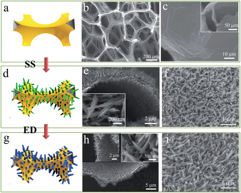 | ||
| Fig. 1 (a, d, and g) Schematic illustration of the fabrication process of graphene foam (GF) supported VO2/HMB core–shell arrays. SEM images of (b and c) GF, (e and f) VO2 nanoflake arrays on GF (the cross-sectional image and fine structure in the inset) and (h and i) VO2/HMB core–shell arrays on GF (the cross-sectional image and fine structure in the inset). | ||
During the annealing process,
| 2VO(OH)3 + H2 → 2VO2 + 4H2O | (4) |
It is noticed that a characteristic blue color appears during the ED of HMB. The electro-deposition reactions of the HMB shell can be simplified as follows.
| 2MoO42− + 4H2O2 → [Mo2(O2)4O3]2− + 2OH− + 3H2O | (5) |
| [Mo2(O2)4O3]2− + (2 + x)H+ + xe− → 2HxMoO3(HMB) + H2O + 2O2 | (6) |
A further insight into the microstructures and phases at different stages is obtained by TEM and HRTEM. The GF exhibits a homogeneous texture with a scrolling edge and a lattice spacing of ∼0.34 nm corresponding to the (002) planes of graphitic carbon (JCPDS 75-1621) (Fig. 2a). The TEM images indicate that the as-prepared VO2 nanoflakes are quite smooth and the average diameter is about 200 nm (Fig. 2b). Additionally, a single crystalline selected area electron diffraction (SAED) pattern of VO2 nanoflakes is observed. Furthermore, the measured lattice spacing of 0.58 nm is consistent with the (200) planes of the VO2 (B) phase (JCPDS 81-2392) (Fig. 2b). For the core–shell nanoflakes, a rougher surface is noticed. From the HRTEM image, it is seen that the HMB shell thickness is ∼15 nm. In our TEM examination, some of the HMB shells are amorphous, in general agreement with the results in the literature.48,49,51 However, as we conducted post-annealing (150 °C in a vacuum for 2 h), a certain level of crystallization can be observed as revealed by the incomplete fringes in Fig. 2d. Such a core–shell nanoflake structure is also demonstrated by the energy dispersive X-ray spectroscopy (EDS) elemental mapping of O, V and Mo (Fig. 2e) and the EDS spectrum (Fig. S2†). The phase evolution is monitored by the XRD measurement (Fig. 3a). Comparing the XRD patterns of different products, it is observed that, except for the peaks of GF, the strong diffraction peaks can be assigned to the monoclinic phase of VO2 (B) (JCPDS 81-2392). No peaks of HMB are observed because of the small thickness and partial crystallization.
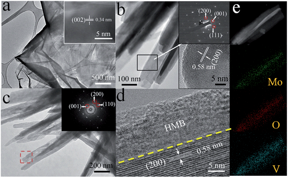 | ||
| Fig. 2 TEM-HRTEM characterizations: (a) GF (HRTEM image in the inset); (b) VO2 nanoflake (SAED pattern and HRTEM image in the inset); (c and d) VO2/HMB core–shell nanoflake (SAED pattern and HRTEM image in the inset); (e) EDS mapping of Mo, O and V. | ||
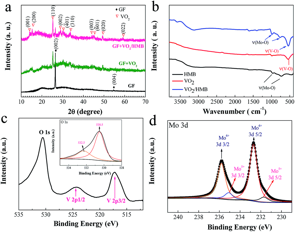 | ||
| Fig. 3 (a) XRD patterns and (b) FTIR spectra of GF, GF + VO2 and GF + VO2/HMB. XPS spectra: (c) V (2p) and O (1s) regions of VO2/HMB; (d) Mo (3d) spectra. | ||
To further verify the components of the core–shell structure, FTIR and XPS measurements were conducted. It is seen that the characteristic FTIR peak of VO2 is located at 539 cm−1,24,30 while the HMB shows typical peaks at around 766 and 987 cm−1 (Fig. 3b).48 The core–shell VO2/HMB contains all the above typical vibration peaks of both VO2 and HMB. In addition, the composition is also supported by XPS analysis (Fig. 3c and d). As shown in Fig. 3c, the XPS peaks of V 2p and O 1s are observed. For the V 2p spectra, the binding energy separation between core levels V 2p1/2 (524.4 eV) and V 2p3/2 (516.9 eV) is ∼7.5 eV, which matches with the electronic states of VO2.30 For the Mo 3d core level, a mixed valence of Mo6+ and Mo5+ exists (Fig. 3d). These are the typical electronic states of HMB.51 Two peaks at 535.8 and 532.7 eV are assigned to Mo6+ (3d3/2) and Mo6+ (3d5/2), and 534.6 and 531.6 eV are due to Mo5+ (3d3/2) and Mo5+ (3d5/2). In the O 1s spectra (inset in Fig. 3c), the peak 530.5 eV is related to the metal–O bond (V–O and Mo–O). The small peak at 532.5 eV is associated with H2O adsorbed on the surface.54 Based on the above results, it is justified that the HMB is successfully coated on the surface of VO2 forming core–shell arrays on the GF substrate.
Using a similar electro-deposition method, we also prepared GF supported VO2/HxWO3 core–shell arrays with different starting precursors (Fig. S3†). A similar morphology is observed for the GF + VO2/HxWO3. In addition, in our experiment, a noteworthy phenomenon is that the VO2 nanoflake arrays act as a strong backbone for the growth of HMB. In a control experiment, the single HMB could not be uniformly electrodeposited directly on the GF substrate; instead, it forms a dense but discontinuous film (Fig. S4†). This is indicative of a poor adhesion of the HMB film on GF. Hence, the nanostructure 3D surfaces of VO2 nanoflakes provide effectively lower-energy sites for the preferable anchoring of the HMB layer. This perfect matching allows the construction of VO2/HMB core–shell nanoflake array electrodes for ultra-stable and high-rate electrochemical energy storage. Last but not least, there is no principle limit for the core oxide materials to VO2; other pseudo-capacitive materials such as MnO2 should also apply.
Performance enhancement as supercapacitor electrodes
In order to evaluate the electrochemical properties of GF + VO2/HMB core–shell arrays, asymmetric supercapacitors (GF + VO2/HMB as the cathode and activated carbon as the anode) have been assembled and comprehensively characterized. First, in the cyclic voltammograms (CVs) at various current densities (Fig. 4a and S5a and b†), both GF + VO2/HMB and the uncoated GF + VO2 electrodes show weak redox peaks and their CV behavior is similar to the quasi-rectangular CV curves of EDLCs.11 It should be highlighted that the scanning rates of CV for supercapacitors need to be higher than 10 mV s−1; scanning rates lower than this are less meaningful for supercapacitors,1 as they do not reflect the high charge–discharge characteristics. In our integrated electrode, VO2 plays a dominating role in the electrochemical energy storage. The charge storage mechanism of VO2 in the neutral K2SO4 electrolyte involves the incorporation of the electrolyte cation K+,| VO2 + xK+ + e− ↔ KxVO2. | (7) |
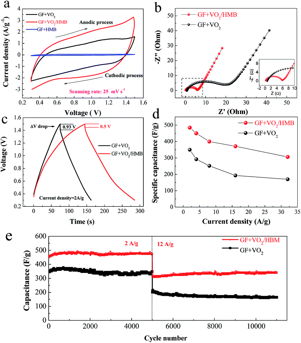 | ||
| Fig. 4 Electrochemical characterization of asymmetric supercapacitors with GF + VO2 and GF + VO2/HMB as the cathode materials (activated carbon as the anode for both cells): (a) CV curves at a scanning rate of 25 mV s−1; (b) Nyquist plots at a fully discharged state; (c) charge–discharge curves at a current density of 2 A g−1; (d) specific capacitances; (e) cycling life at different current densities. | ||
Meanwhile, the K+ ions could be incorporated into the HMB according to the simplified reaction:10,55,56
| HxMO3 + yK+ + ye− ↔ KyHxMO3 | (8) |
However, the HMB mainly serves as a transport channel for ions between the electrolyte and the inner VO2 core; the ion storage contribution is very small because of its low weight ratio in the composite, which can be seen from the CV curve of GF + HMB (Fig. 4a). It is well accepted that the specific capacitance and electrochemical activity of active materials are proportional to the enclosed CV area. From the CV experiments, a higher current density and a bigger CV area are noticed for the GF + VO2/HMB than the uncoated GF + VO2 electrode at the same current density (Fig. 4a).
The improved reaction reactivity of the GF + VO2/HMB electrode is supported by the electrochemical impedance spectrum (EIS) test (Fig. 4b). Comparatively, the GF + VO2/HMB electrode has lower electrode series resistance (derived from the high frequency intersection of the Nyquist plot in the real axis) and a smaller semi-arc originated from the charge transfer process of Faradaic reactions in the high–medium frequency region. It is indicated that the GF + VO2/HMB electrode has faster reaction kinetics than the GF + VO2 counterpart due to the more efficient conductive network constructed by the HMB shell. Fig. 4c shows the typical charge–discharge profiles of the two electrodes at 2 A g−1. The GF + VO2/HMB electrode exhibits a lower charge voltage and higher discharge voltage than the GF + VO2 electrode, indicating that the former has a smaller polarization during the charge–discharge process, supported by the voltage drop during the initial discharge process. Note that the initial voltage drop of the GF + VO2/HMB electrode (0.5 V) is much smaller than the GF + VO2 electrode (0.93 V). The energy density (E) of a supercapacitor is E = 1/2CU2, where C is the capacitance and U is the discharge voltage. Generally, a high polarization leads to a low discharge voltage, which will decrease the energy and power densities. In our experiment, the integrated conductive network helps to transport the charge efficiently and diminish the polarization, resulting in a higher discharge voltage.
The discharge curves and the corresponding specific capacitances of the two electrodes are presented in Fig. S5c and d and 4d.† The GF + VO2/HMB electrode exhibits a much better high-rate capability with specific capacitances from 485 F g−1 (2 A g−1) to 306 F g−1 (32 A g−1) (based on the mass of the cathode), higher than those of the GF + VO2 (350 F g−1 at 2 A g−1 and 170 F g−1 at 32 A g−1). The obtained values are also higher than CNT/GF (100 F g−1 at 1 A g−1),57 ZnO/GF (316 F g−1 at 6 A g−1),58 and PANI/GF (346 F g−1 at 4 A g−1),59 and other vanadium oxide powder counterparts such as CNTs/VO2 (250 F g−1 at 2 A g−1),31 hydrogen treated VO2 (300 F g−1),38 and RGO/VO2 composites (225 at 1 A g−1).29,30 The corresponding comparison is shown in Table S1 in the ESI.† Additionally, we also tested the thickness effect of HMB on the capacitance. Fig. S5e† shows the discharge curves of GF + VO2/HMB electrodes with four different HMB thicknesses (∼5, ∼10, ∼15, and ∼20 nm corresponding, respectively, to the electrodeposition time of 400, 800, 1200, and 1600 s). It is found that, while the difference is insignificant, the electrode with 15 nm HMB shows the highest capacitance (450 F g−1) compared to the other thicknesses (409 F g−1 for 5 nm HMB, 420 F g−1 for 10 nm HMB and 426 F g−1 for 20 nm HMB). The power and energy densities of the assembled asymmetric supercapacitor were also calculated (based on the mass of the cathode, separator and anode). Fig. S5f† shows the Ragone plot (energy density vs. power density) measured in the voltage window of 0.3 to 1.5 V at different current densities. The supercapacitor with GF + VO2/HMB presents an energy density range from 14.5 to 9.2 W h kg−1 when the power density changes from 0.72 to 11.5 kW kg−1, superior to the GF + VO2 (from 10.5 to 5.1 W h kg−1).
These results reveal the high specific capacitance and notable high-rate capability of the GF + VO2/HMB electrode for high-performance supercapacitors. The enhanced properties of the GF + VO2/HMB electrode mainly come from the integrated porous conductive architecture. The VO2 nanoflakes are not only directly grown on the GF substrate, but also homogeneously wrapped by the thin HMB shell, which can provide both high electron and ion transfer paths. This intimate binding and conductive network can provide fast and short electron/ion transfer paths, thus leading to fast reaction kinetics with good high-rate performance. Meanwhile, the “dead” mass could be avoided and most of the active materials are electrochemically active in the integrated electrode. Furthermore, the 3D porous structure with large inner space and reaction surface could facilitate the efficient contact between the active materials and the electrolytes, leading to the improved utilization of active materials and high capacitance.
Cycling stability is a critical parameter for high-performance supercapacitors. Fig. 4e presents the cycle characteristics of the two electrodes at 2 and 12 A g−1. During the cycle processes, the GF + VO2/HMB exhibits higher specific capacitance and better cycling stability than the GF + VO2. The GF + VO2/HMB electrode shows stable capacitances of 473 F g−1 at 2 A g−1 after 5000 cycles and 340 F g−1 at 12 A g−1 after 11![[thin space (1/6-em)]](https://www.rsc.org/images/entities/char_2009.gif) 000 cycles, respectively, and no obvious capacitance decrease is observed. These values are much higher than the corresponding GF + VO2 electrode (333 F g−1 at 2 A g−1 and 163 F g−1 at 12 A g−1). As the cycle life is highly related to the structural stability of the electrode, we disassembled the supercapacitors to check the morphology of the electrodes after 11000 cycles (Fig. S6†). It is found that the GF + VO2/HMB electrode preserves its array structure, whereas the uncoated nanoflakes in the GF + VO2 electrode are prone to aggregate into bundles and tend to collapse. Therefore, it is inferred that the introduction of the HMB shell not only provides an electrical conductive path, but also helps to alleviate the structure damage.
000 cycles, respectively, and no obvious capacitance decrease is observed. These values are much higher than the corresponding GF + VO2 electrode (333 F g−1 at 2 A g−1 and 163 F g−1 at 12 A g−1). As the cycle life is highly related to the structural stability of the electrode, we disassembled the supercapacitors to check the morphology of the electrodes after 11000 cycles (Fig. S6†). It is found that the GF + VO2/HMB electrode preserves its array structure, whereas the uncoated nanoflakes in the GF + VO2 electrode are prone to aggregate into bundles and tend to collapse. Therefore, it is inferred that the introduction of the HMB shell not only provides an electrical conductive path, but also helps to alleviate the structure damage.
Li-ion storage properties of the VO2/HMB core–shell nanoflake electrode
To further demonstrate the potential application of the GF + VO2/HMB electrode, we also tested its electrochemical properties as the cathode of lithium ion batteries. Fig. 5a shows the CV curve of the GF + VO2/HMB electrode at a scanning rate of 0.1 mV s−1 between 1.5 and 3.5 V at the second cycle. The simplified reaction between the lithium ion and VO2 is expressed as follows.21,60,61| VO2 + xLi+ + xe− ↔ LixVO2 | (9) |
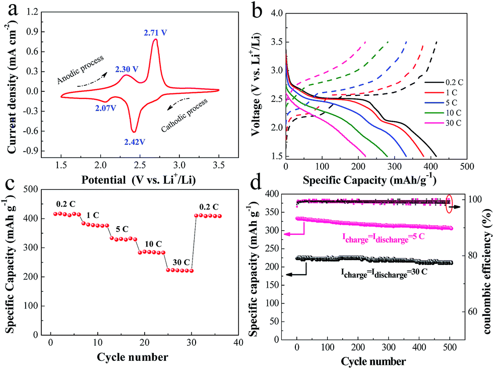 | ||
| Fig. 5 Electrochemical characterization of the GF + VO2/HMB electrode as the cathode of lithium ion batteries: (a) CV curves at a scanning rate of 0.1 mV s−1 at the 2nd cycle; (b) charge–discharge curves at different current densities and (c) rate capabilities; (d) cycling life at different current densities. | ||
In our case, two pairs of redox peaks are noticed in the CV curve, both of which can be ascribed to the Li-ion reaction with VO2. In comparison, the CV intensity of the HMB alone (namely, GF + HMB) is very small. This means a negligible CV contribution (lower than 1.5%) and subsequent capacity contribution from HMB. During the anodic process, two peaks at about 2.30 and 2.71 V are observed corresponding to the desertion of lithium from host structures. For the cathodic process, there are two reduction peaks at 2.42 and 2.07 V attributed to the insertion of lithium into VO2. However, the detailed reaction mechanism between VO2 and the lithium ion is still unclear. One or two redox peaks can be observed in their CV curves according to the literature.21,60–64 This different CV behavior is supposed to be associated with the multiple reversible insertion/desertion of lithium in the VO2 host structure.
The charge–discharge curves of the GF + VO2/HMB electrode at different rates and high-rate capability are shown in Fig. 5b and c. The charge–discharge plateaus observed are consistent with the CV results. The GF + VO2/HMB electrode delivers a specific capacity of 415 mA h g−1 at 0.2 C and 380 mA h g−1 at 1 C. Impressively, the GF + VO2/HMB electrode exhibits excellent high-rate capability with a specific capacity of 280 mA h g−1 at 10 C and 219 mA h g−1 at 30 C, respectively. The corresponding charge–discharge Coulombic efficiency is about 99%. The obtained values are much higher than the commercial LiCoO2,65 LiFePO4,66 LiMnO4,67 and other VO2 powder materials,61–64 and comparable to the graphene/VO2 ribbon.60 It should be noted that when the current rate is decreased to 0.2 C, a high discharge capacity of 415 mA h g−1 can be regained. In addition, the GF + VO2/HMB electrode presents superior high-rate cycling stability (Fig. 5d). After 500 cycles, a high reversible capacity of 305 mA h g−1 at 5 C (a capacity retention of 91.8%) and 209 mA h g−1 at 30 C (a capacity retention of 95.4%) is obtained, respectively, superior to those of VO2 powder materials.61–64 Based on the above results, it is justified that the integrated electrode design and HMB modification can work together to achieve a high-performance cathode for electrochemical energy storage devices.
Conclusions
In conclusion, we have demonstrated a new shell material, hydrogen molybdenum bronze (HMB), for the construction of metal oxide based core–shell nanoarray electrodes and their enhanced electrochemical performances. The HMB shell is proven to be a promising shell material for high-performance supercapacitors because of its interesting properties with both high electrical conductivity and ionic conductivity. Due to the unique composition and integrated conductive architecture, the GF + VO2/HMB integrated electrode shows excellent electrochemical performances in asymmetric supercapacitors with higher capacitance, weaker polarization, and better cycling performance as compared to the GF + VO2 electrode. Moreover, the GF + VO2/HMB integrated electrode is also demonstrated as a superior cathode of lithium ion batteries with noticeable high-rate capability. Prospectively, the electrodeposited HMB can be an effective shell material for a wide range of metal oxides to enhance their performance in batteries, supercapacitors and fuel cells.Acknowledgements
This work is supported by the SERC Public Sector Research Funding (Grant number 1121202012), Agency for Science, Technology, and Research (A*STAR). H.Z. thanks the support from MOE AcRF Tier 2 (ARC 26/13, no. MOE2013-T2-1-034) and AcRF Tier 1 (RG 61/12, RGT18/13, and RG5/13), and Start-up Grant (M4080865.070) in Singapore. This Research is also conducted by the NTU-HUJ-BGU Nanomaterials for Energy and Water Management Programme under the Campus for Research Excellence and Technological Enterprise (CREATE), which is supported by the National Research Foundation, Prime Minister's Office, Singapore. The authors also acknowledge support from the Energy Research Institute @NTU (ERI@N).References
- P. Simon, Y. Gogotsi and B. Dunn, Science, 2014, 343, 1210 CrossRef CAS PubMed.
- J. R. Miller and P. Simon, Science, 2008, 321, 651 CrossRef CAS PubMed.
- X. Huang, Z. Y. Yin, S. X. Wu, X. Y. Qi, Q. Y. He, Q. C. Zhang, Q. Y. Yan, F. Boey and H. Zhang, Small, 2011, 7, 1876 CrossRef CAS PubMed.
- X. Huang, Z. Y. Zeng, Z. X. Fan, J. Q. Liu and H. Zhang, Adv. Mater., 2012, 24, 5979 CrossRef CAS PubMed.
- Y. W. Zhu, S. Murali, M. D. Stoller, K. J. Ganesh, W. W. Cai, P. J. Ferreira, A. Pirkle, R. M. Wallace, K. A. Cychosz, M. Thommes, D. Su, E. A. Stach and R. S. Ruoff, Science, 2011, 332, 1537 CrossRef CAS PubMed.
- Y. He, W. Chen, C. Gao, J. Zhou, X. Li and E. Xie, Nanoscale, 2013, 5, 8799 RSC.
- C. H. Xu, B. H. Xu, Y. Gu, Z. G. Xiong, J. Sun and X. S. Zhao, Energy Environ. Sci., 2013, 6, 1388 CAS.
- Y. Zhang, H. Feng, X. B. Wu, L. Z. Wang, A. Q. Zhang, T. C. Xia, H. C. Dong, X. F. Li and L. S. Zhang, Int. J. Hydrogen Energy, 2009, 34, 4889 CrossRef CAS PubMed.
- C. Liu, F. Li, L. P. Ma and H. M. Cheng, Adv. Mater., 2010, 22, E28 CrossRef CAS PubMed.
- P. Simon and Y. Gogotsi, Nat. Mater., 2008, 7, 845 CrossRef CAS PubMed.
- G. P. Wang, L. Zhang and J. J. Zhang, Chem. Soc. Rev., 2012, 41, 797 RSC.
- V. Augustyn, P. Simon and B. Dunn, Energy Environ. Sci., 2014, 7, 1597 CAS.
- R. S. Devan, R. A. Patil, J.-H. Lin and Y.-R. Ma, Adv. Funct. Mater., 2012, 22, 3326 CrossRef CAS.
- F. Wang, S. Xiao, Y. Hou, C. Hu, L. Liu and Y. Wu, RSC Adv., 2013, 3, 13059 RSC.
- X. Xia, Y. Zhang, D. Chao, C. Guan, Y. Zhang, L. Li, X. Ge, I. M. Bacho, J. Tu and H. J. Fan, Nanoscale, 2014, 6, 5008 RSC.
- X. H. Xia, J. P. Tu, Y. Q. Zhang, J. Chen, X. L. Wang, C. D. Gu, C. Guan, J. S. Luo and H. J. Fan, Chem. Mater., 2012, 24, 3793 CrossRef CAS.
- J. T. Zhang and X. S. Zhao, ChemSusChem, 2012, 5, 818 CrossRef CAS PubMed.
- X. Xia, C. Zhu, J. Luo, Z. Zeng, C. Guan, C. F. Ng, H. Zhang and H. J. Fan, Small, 2014, 10, 766 CrossRef PubMed.
- Q. An, P. Zhang, Q. Wei, L. He, F. Xiong, J. Sheng, Q. Wang and L. Mai, J. Mater. Chem. A, 2014, 2, 3297 CAS.
- L. Q. Mai, Q. Y. An, Q. L. Wei, J. Y. Fei, P. F. Zhang, X. Xu, Y. L. Zhao, M. Y. Yan, W. Wen and L. Xu, Small, 2014, 10, 3032 CrossRef CAS PubMed.
- C. Niu, J. Meng, C. Han, K. Zhao, M. Yan and L. Mai, Nano Lett., 2014, 14, 2873 CrossRef CAS PubMed.
- X. C. Tian, X. Xu, L. He, Q. L. Wei, M. Y. Yan, L. Xu, Y. L. Zhao, C. C. Yang and L. Q. Mai, J. Power Sources, 2014, 255, 235 CrossRef CAS PubMed.
- L. Zhang, K. N. Zhao, W. W. Xu, J. S. Meng, L. He, Q. Y. An, X. Xu, Y. Z. Luo, T. W. Zhao and L. Q. Mai, RSC Adv., 2014, 4, 33332 RSC.
- J. Zhu, L. Cao, Y. Wu, Y. Gong, Z. Liu, H. E. Hoster, Y. Zhang, S. Zhang, S. Yang, Q. Yan, P. M. Ajayan and R. Vajtai, Nano Lett., 2013, 13, 5408 CrossRef CAS PubMed.
- M. P. Yeager, W. Du, B. Bishop, M. Sullivan, W. Xu, D. Su, S. D. Senanayake, J. Hanson and X. Teng, ChemSusChem, 2013, 6, 2231 CrossRef CAS PubMed.
- K. Jeyalakshmi, S. Vijayakumar, K. K. Purushothaman and G. Muralidharan, Mater. Res. Bull., 2013, 48, 2578 CrossRef CAS PubMed.
- K. Jeyalakshmi, S. Vijayakumar, S. Nagamuthu and G. Muralidharan, Mater. Res. Bull., 2013, 48, 760 CrossRef CAS PubMed.
- C. Wu, F. Feng and Y. Xie, Chem. Soc. Rev., 2013, 42, 5157 RSC.
- L. Deng, G. Zhang, L. Kang, Z. Lei, C. Liu and Z.-H. Liu, Electrochim. Acta, 2013, 112, 448 CrossRef CAS PubMed.
- H. Wang, H. Yi, X. Chen and X. Wang, J. Mater. Chem. A, 2014, 2, 1165 CAS.
- L. Liang, H. Liu and W. Yang, J. Alloys Compd., 2013, 559, 167 CrossRef CAS PubMed.
- S. D. Perera, B. Patel, N. Nijem, K. Roodenko, O. Seitz, J. P. Ferraris, Y. J. Chabal and K. J. Balkus Jr, Adv. Energy Mater., 2011, 1, 936 CrossRef CAS.
- M. Sathiya, A. S. Prakash, K. Ramesha, J. M. Tarascon and A. K. Shukla, J. Am. Chem. Soc., 2011, 133, 16291 CrossRef CAS PubMed.
- M. Epifani, T. Chavez-Capilla, T. Andreu, J. Arbiol, J. Palma, J. R. Morante and R. Diaz, Energy Environ. Sci., 2012, 5, 7555 CAS.
- H. T. Tan, X. Rui, H. Yu, W. Liu, C. Xu, Z. Xu, H. H. Hng and Q. Yan, ACS Nano, 2014, 8, 4004 CrossRef CAS PubMed.
- L. Mai, F. Dong, X. Xu, Y. Luo, Q. An, Y. Zhao, J. Pan and J. Yang, Nano Lett., 2013, 13, 740 CrossRef CAS PubMed.
- Q. Qu, Y. Zhu, X. Gao and Y. Wu, Adv. Energy Mater., 2012, 2, 950 CrossRef CAS.
- X. Pan, Y. Zhao, G. Ren and Z. Fan, Chem. Commun., 2013, 49, 3943 RSC.
- X. H. Cao, Y. M. Shi, W. H. Shi, G. Lu, X. Huang, Q. Y. Yan, Q. C. Zhang and H. Zhang, Small, 2011, 7, 3163 CrossRef CAS PubMed.
- Z. P. Chen, W. C. Ren, L. B. Gao, B. L. Liu, S. F. Pei and H. M. Cheng, Nat. Mater., 2011, 10, 424 CrossRef CAS PubMed.
- J. J. Yoo, K. Balakrishnan, J. S. Huang, V. Meunier, B. G. Sumpter, A. Srivastava, M. Conway, A. L. M. Reddy, J. Yu, R. Vajtai and P. M. Ajayan, Nano Lett., 2011, 11, 1423 CrossRef CAS PubMed.
- X. Xia, D. Chao, Z. Fan, C. Guan, X. Cao, H. Zhang and H. J. Fan, Nano Lett., 2014, 14, 1651 CrossRef CAS PubMed.
- X.-C. Dong, H. Xu, X.-W. Wang, Y.-X. Huang, M. B. Chan-Park, H. Zhang, L.-H. Wang, W. Huang and P. Chen, ACS Nano, 2012, 6, 3206 CrossRef CAS PubMed.
- H. X. Ji, L. L. Zhang, M. T. Pettes, H. F. Li, S. S. Chen, L. Shi, R. Piner and R. S. Ruoff, Nano Lett., 2012, 12, 2446 CrossRef CAS PubMed.
- J. Ji, L. L. Zhang, H. Ji, Y. Li, X. Zhao, X. Bai, X. Fan, F. Zhang and R. S. Ruoff, ACS Nano, 2013, 7, 6237 CrossRef CAS PubMed.
- L. L. Peng, X. Peng, B. R. Liu, C. Z. Wu, Y. Xie and G. H. Yu, Nano Lett., 2013, 13, 2151 CrossRef CAS PubMed.
- K. Chin, K. Eda, N. Sotani and M. S. Whittingham, J. Solid State Chem., 2002, 164, 81 CrossRef CAS.
- K. Eda, J. Solid State Chem., 1989, 83, 292 CrossRef CAS.
- K. Eda, J. Solid State Chem., 1992, 98, 350 CrossRef CAS.
- D. Tinet, P. Canesson, H. Estrade and J. J. Fripiat, J. Phys. Chem. Solids, 1980, 41, 583 CrossRef CAS.
- F. Xie, W. C. H. Choy, C. Wang, X. Li, S. Zhang and J. Hou, Adv. Mater., 2013, 25, 2051 CrossRef CAS PubMed.
- X. Xia, D. Chao, Z. Fan, C. Guan, X. Cao, H. Zhang and H. J. Fan, Nano Lett., 2014, 14, 1651 CrossRef CAS PubMed.
- D. Chao, X. Xia, J. Liu, Z. Fan, C. F. Ng, J. Lin, H. Zhang, Z. X. Shen and H. J. Fan, Adv. Mater., 2014, 26, 5794 CrossRef CAS PubMed.
- R. Casanova, J. Mendialdua and Y. Barbaux, J. Electron Spectrosc. Relat. Phenom., 1995, 71, 249 CrossRef.
- X. Y. Lang, A. Hirata, T. Fujita and M. W. Chen, Nat. Nanotechnol., 2011, 6, 232 CrossRef CAS PubMed.
- M. Toupin, T. Brousse and D. Belanger, Chem. Mater., 2004, 16, 3184 CrossRef CAS.
- Z. Yan, L. Ma, Y. Zhu, I. Lahiri, M. G. Hahm, Z. Liu, S. Yang, C. Xiang, W. Lu, Z. Peng, Z. Sun, C. Kittrell, J. Lou, W. Choi, P. M. Ajayan and J. M. Tour, ACS Nano, 2012, 7, 58 CrossRef PubMed.
- X. Dong, Y. Cao, J. Wang, M. B. Chan-Park, L. Wang, W. Huang and P. Chen, RSC Adv., 2012, 2, 4364 RSC.
- X. Dong, J. Wang, J. Wang, M. B. Chan-Park, X. Li, L. Wang, W. Huang and P. Chen, Mater. Chem. Phys., 2012, 134, 576 CrossRef CAS PubMed.
- S. Yang, Y. Gong, Z. Liu, L. Zhan, D. P. Hashim, L. Ma, R. Vajtai and P. M. Ajayan, Nano Lett., 2013, 13, 1596 Search PubMed.
- L. Mai, Q. Wei, Q. An, X. Tian, Y. Zhao, X. Xu, L. Xu, L. Chang and Q. Zhang, Adv. Mater., 2013, 25, 2969 CrossRef PubMed.
- Q. Zhao, L. Jiao, W. Peng, H. Gao, J. Yang, Q. Wang, H. Du, L. Li, Z. Qi, Y. Si, Y. Wang and H. Yuan, J. Power Sources, 2012, 199, 350 CrossRef CAS PubMed.
- X. Rui, D. Sim, C. Xu, W. Liu, H. Tan, K. Wong, H. H. Hng, T. M. Lim and Q. Yan, RSC Adv., 2012, 2, 1174 RSC.
- H. Liu, Y. Wang, K. Wang, E. Hosono and H. Zhou, J. Mater. Chem., 2009, 19, 2835 RSC.
- Q. Zhang, E. Uchaker, S. L. Candelaria and G. Cao, Chem. Soc. Rev., 2013, 42, 3127 RSC.
- C. Liu, F. Li, L. P. Ma and H. M. Cheng, Adv. Mater., 2010, 22, E28 CrossRef CAS PubMed.
- J. M. Tarascon and M. Armand, Nature, 2001, 414, 359 CrossRef CAS PubMed.
Footnotes |
| † Electronic supplementary information (ESI) available: Material preparation and synthetic details. Fig. S1 and S2: photos and the EDS spectrum of GF supported VO2/HMB core–shell array electrodes. Fig. S3: SEM and TEM images of GF supported VO2/HxWO3 core–shell arrays. Fig. S4: SEM images of GF supported HMB films. Fig. S5: electrochemical characterization of asymmetric supercapacitors with GF + VO2/HMB and GF + VO2 as the cathode material. Fig. S6: SEM and TEM images of two electrodes after 11000 cycles. See DOI: 10.1039/c4mh00212a |
| ‡ Xinhui Xia and Dongliang Chao contributed equally to this work. |
| This journal is © The Royal Society of Chemistry 2015 |