Recent advances in BiOX (X = Cl, Br and I) photocatalysts: synthesis, modification, facet effects and mechanisms
Liqun
Ye
*,
Yurong
Su
,
Xiaoli
Jin
,
Haiquan
Xie
* and
Can
Zhang
College of Chemistry and Pharmaceutical Engineering, Nanyang Normal University, Nanyang 473061, People's Republic of China. E-mail: yeliquny@163.com; Xie-hq@163.com
First published on 11th February 2014
Abstract
Photocatalysis technology, using semiconductor nano-materials to decompose toxic pollutants under solar light irradiation, displays great prospects for environmental protection. This review gives an overview of the applications of BiOX (X = Cl, Br and I) photocatalysts for efficient photocatalytic degradation (PCD) removal of pollutants in water/air, such as volatile organic compounds (VOCs), organic molecule pollutants, polymer pollutants and biological substances. In addition, the hybridization, facet effects and photocatalytic mechanisms of BiOX are highlighted to offer guidelines for designing highly-active BiOX visible-light-driven (VLD) photocatalysts. Furthermore, the research trends and future prospects of BiOX photocatalysts are also briefly summarized. It may lead to feasible green and efficient photocatalytic reaction systems using BiOX as the photocatalyst.
 Liqun Ye | Liqun Ye obtained his BS degree from Qiqihar University, China, in 2008, and his PhD degree from Wuhan University, China, in 2013, under the supervision of Prof. Ling Zan. At present, he works in Nanyang Normal University, China. His current research concentrates on the synthesis of 2D photo-functional materials and their applications in the fields of environmental remediation and new energy production. |
 Yurong Su | Yurong Su obtained her BS degree from the Xinxiang Medical University, China, in 2013. She then moved to the College of Chemistry and Pharmaceutical Engineering in Nanyang Normal University for her Masters degree studies under the supervision of Dr Liqun Ye and Prof. Haiquan Xie. She is interested in the synthesis and properties of nanostructured photocatalytic materials. |
 Xiaoli Jin | Xiaoli Jin obtained her BS degree from the Nanyang Normal University, China, in 2013. She then started her Masters degree studies under the supervision of Prof. Haiquan Xie. She is interested in developing new photocatalysts, electronic structures of semiconductor photocatalysts, and mechanisms of photocatalysis. |
 Haiquan Xie | Haiquan Xie received his PhD degree in applied chemistry from East China University of Science and Technology, China, in 2002. He has been a professor at the College of Chemistry and Pharmaceutical Engineering at Nanyang Normal University since 2011. Today, he is the director of the College of Chemistry and Pharmaceutical Engineering at Nanyang Normal University with scientific interests in functional materials. |
Nano impactIn the area of environmental remediation, photocatalytic technology using nano-photocatalysts is one of the most important parts. In the past ten years, BiOX (X = Cl, Br and I) 2D nanosheets and 3D hierarchical structures with 2D nanoflakes have offered potential for efficient photocatalytic degradation (PCD) removal of pollutants in air, water and biological contaminants. Based on the layer structure characterized as [Bi2O2] slabs interleaved by double slabs of halogen atoms, BiOX 2D crystals show open crystalline structures and indirect optical transitions. So, they display very high photocatalytic activity for environmental remediation. On the other hand, the thickness and exposed facets of BiOX 2D crystals also affect their photocatalytic performance and mechanism. |
1. Introduction
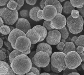
With industrialization and urbanization increasing, the contamination caused by gases, organic molecule pollutants, polymer pollutants and biological substances is becoming a severe problem.1–3 Furthermore, many anthropogenic organic pollutants with very low concentrations and high toxicity, require effective and “green” techniques to chemically transform them into non-hazardous compounds without secondary pollution.4–6 In the past years, physical treatment methods (adsorption, ultrafiltration, coagulation, etc.) and chemical degradation methods (including ozone/UV radiation/H2O2 oxidation, semiconductor photocatalysis techniques, supercritical water oxidation, the Fenton method, sonochemical degradation, electrochemical methods, the electron beam process, solvated electron reduction, permeable reactive barriers of iron, and enzymatic treatment methods) have been the main techniques to remove the organic pollutants.7,8 Among these techniques, semiconductor photocatalysis techniques can completely eliminate the organic pollutants rapidly, cheaply, and in an environmentally friendly manner. And it has been suggested as one of the most effective and “green” methods to remove organic pollutants.9–12There is no doubt that the photocatalyst is the most important part of the photocatalytic technology. Therefore, the development of high-performance photocatalysts has attracted great interest. To date, there are two main synthesis strategies that have been investigated for the preparation of high-performance photocatalysts. The first one is to extend the modification of conventional photocatalysts (TiO2 and ZnO) by doping, coupling, and sensitization. The other strategy is to develop new photocatalysts. The first strategy has been studied deeply, but it still cannot satisfy the requirements for practical application. So, many researchers have now explored new photocatalysts, such as simple oxides, sulfides, complex oxides, and polymers.13–17 BiOX (X = Cl, Br, I) are important V–VI–VII ternary semiconductor compounds because of their optical properties. All BiOX have a tetragonal matlockite structure, a layer structure characterized by [Bi2O2] slabs interleaved by double slabs of halogen atoms as shown in Fig. 1. Many years ago, they were usually applied as catalysts,18,19 ferroelectric materials,20 storage materials,21 and pigments.22 In the past five years, BiOX have been reported as efficient photocatalysts to decompose pollutants into non-toxic molecules for environmental remediation. And more and more researchers have been studying the photocatalytic performance of BiOX under sunlight irradiation.
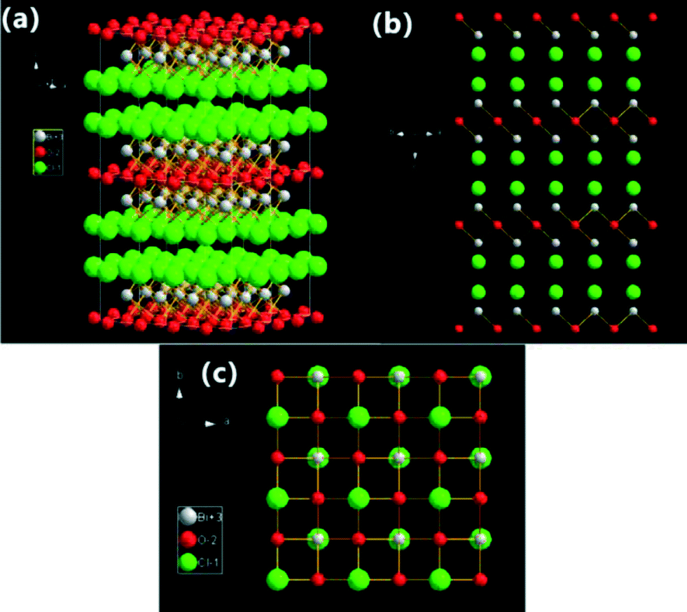 | ||
| Fig. 1 Structure model illustrations of BiOCl crystals (3 × 3 lattices): (a) three-dimensional projection; (b) {110} facets; and (c) {001} facets. | ||
The high photocatalytic activity of BiOX is mainly caused by their open crystalline structures and the indirect optical transition. The indirect-transition band-gap means that the excited electron has to travel a certain k-space distance to be emitted to the valence band (VB) which reduces the recombination probability of the excited electron and the hole.23–28 On the other hand, the open layered crystalline structure provides a large enough space to polarize the related atoms and orbitals, and then induce the presence of internal static electric fields perpendicular to the [Bi2O2] slabs and halogen anionic slabs in BiOX.23–28 At the end, effective separation of the photoinduced electron–hole pairs along the [001] direction can be displayed. So, BiOX display high photocatalytic activities. Among all the BiOX samples, BiOCl exhibits the best photocatalytic activity under UV light, even higher than TiO2 (P25, Degussa) for photocatalytic degradation (PCD) of dyes. BiOI exhibits the best visible-light-driven (VLD) photocatalytic activity for PCD of organic pollutants attributed to its smaller band gap. BiOBr shows an appropriate band-gap (2.7 eV) which results in the best photocatalytic oxidation and reduction activity under full light spectrum irradiation.
At present, gas-phase photocatalysis (the semiconductor photocatalysis technique is used to eliminate gas-phase substrates) and liquid-phase photocatalysis (the semiconductor photocatalysis technique is used to eliminate liquid-phase substrates) of BiOX have been researched widely. But solid-phase photocatalysis (the semiconductor photocatalysis technique is used to eliminate solid-phase substrates29–33) has been little studied due to its long research cycle. For example, all dyes, alcohols, phenols, benzene compounds, heavy metals, E. coli, and bacteria can be decomposed by BiOX via liquid-phase photocatalysis under light irradiation. NOx can be decomposed by BiOX via gas-phase photocatalysis. Poly(vinyl chloride) can be decomposed by BiOI via solid-phase photocatalysis.29
In this brief review, we summarize the recent advances in BiOX research. It may give us insight into the trends in the development of BiOX for environmental protection. Compared to a previous review in Nanoscale,33 there is much different content. And this review focuses on the modification, facet effects and photocatalytic mechanisms of BiOX for efficient photocatalytic environmental protection, rather than the nanostructure of BiOX. The detailed pollutant degradation pathways and the intermediates of mainly pollutants are also shown. It can offer guidelines to design much higher active BiOX VLD photocatalysts for environmental photocatalysis. Furthermore, the research trends and future prospects of BiOX photocatalysts are also briefly summarized.
2. Synthesis
2.1 Synthesis methods
As we know, the synthesis method can affect the morphology, size and surface area of the photocatalyst, which decide the adsorption properties and photocatalytic activity. An inexpensive and “green” method is also necessary for industrialization.34–37Table 1 shows a summary of typical synthesis methods, morphologies and photocatalytic activities of BiOX. The bismuth sources include Bi(NO3)3·5H2O, NaBiO3·2H2O, Bi2O3, Bi, BiCl3 and BiI3. And KX, NaX, HX, CTAX (X = Cl, Br or I) and ionic liquids with halogen elements are usually used as the halogen source.38–66 The main synthesis methods of BiOX include solvothermal, precipitation, the reverse microemulsion route, the molecular precursor route, calcination, microwave irradiation, ionic liquid modified processes, etc. In addition, the reaction temperature, reaction time and pH value also can affect the morphology and size of BiOX.| Synthesis method | Morphology | Photocatalytic activity | Ref. | |
|---|---|---|---|---|
| BiOX | Solvothermal process: Bi(NO3)3·5H2O, ethylene glycol, KX (X = Cl, Br, I); 160 °C for 12 h. |
|
Substrate: MO; UV-visible: BiOI > BiOBr > BiOCl > P25; visible: BiOI > BiOBr > BiOCl > C–TiO2 | 38 |
| Precipitate process: NaBiO3·2H2O, HX (X = Cl, Br, I); room temperature. |
|
Substrate: PCP-Na; Xenon-lamp: BiOI > BiOBr > BiOCl > P25 | 39 | |
| Precipitate process: Bi2O3, HX (X = Cl, Br, I); room temperature. |
|
Substrate: RhB; O2 evolution; UV-visible: BiOI > BiOBr > BiOCl > C–TiO2 | 40 | |
| Solvothermal process: Bi, NaCl, H2O2 (36% in v/v); 160–200 °C for 10 h. |
|
No data | 41 | |
| Reverse microemulsions: Bi(NO3)3·5H2O, KX (X = Cl, Br, I), Marlophen NP5; room temperature. |
|
No data | 42 | |
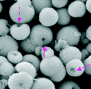
| BiOCl | Solvothermal process: Bi(NO3)3·5H2O, KCl, HNO3, PVP; 180 °C for 18 h |
|
Substrate: MO; UV: BiOCl > P25; visible: BiOCl > P25 | 43 |
| Molecular precursor route: BiCl3, thiourea; room temperature; pH = 4 |
|
Substrate: RhB; UV: BiOCl > P25 | 44 | |
| Low-temperature chemical vapor transport: BiCl3; 250 °C |
|
No data | 45 | |
| Solvothermal process: BiCl3, pyridine; 180 °C for 12 h |
|
Substrate: MO; UV: BiOCl > P25; visible: BiOCl > P25 | 46 | |
| Calcination process: BiCl3; 400 °C for 2 h |
|
Substrate: RhB; UV: BiOCl > P25 | 47 | |
| Solvothermal process: Bi(NO3)3·5H2O, NaCl, ethylene glycol, diethylene glycol; 150 °C for 3 h |
|
Substrate: RhB; visible: BiOCl > P25 | 48 | |
| BiOBr | Microwave irradiation process: Bi(NO3)3·5H2O, CTAB, diethylene glycol; 180 °C for 10 min |
|
Substrate: MO, RhB and phenol; high-pressure mercury lamp: BiOBr > P25 | 49 |
| Ionothermal synthesis: Bi(NO3)3·5H2O, 1-butyl-3-methyl-imidazolium bromide; 200 °C for 24 h |
|
Substrate: Micrococcus lylae; 15 W fluorescent lamp: BiOBr microspheres > BiOBr nanosheets | 50 | |
| Solvothermal process: Bi(NO3)3·5H2O, CTAB, ethylene glycol; 180 °C for 12 h |
|
Substrate: tetrabromobisphenol A; solar light: BiOBr > P25 | 51 | |
| Solvothermal process: Bi(NO3)3·5H2O, CTAB; 150 °C for 24 h |
|
Substrate: toluene; UV: BiOBr > P25; UV-visible: BiOBr > P25 | 52 | |
| Miniemulsion-mediated route: Bi(NO3)3·5H2O, ([C16Mim]Br), 2-methoxyethanol; 160 °C for 0.5–24 h |
|
Substrate: RhB and CrVI; visible: BiOBr hollow microspheres > BiOBr nanoplates > N-P25 | 53 | |
| Solvothermal process: Bi(NO3)3·5H2O, CTAB, ethylene glycol; 180 °C for 12 h |
|
Substrate: no; visible: BiOBr microspheres > BiOBr bulk powders | 54 | |
| Solvothermal process: Bi(NO3)3·5H2O, acetic acid, KBr; 150 °C for 18 h |
|
Substrate: MO; Xenon lamp: BiOBr > P25 | 55 | |
| BiOI | Ionic liquid modified precipitate process: Bi(NO3)3·5H2O, [Bmim]I; 70 °C for 0.5 h |
|
Substrate: MO; visible: BiOI > C–TiO2 | 56 |
| Ionic liquid modified solvothermal process: Bi(NO3)3·5H2O, [Bmim]I; 140 °C for 24 h |
|
Substrate: MO; visible: BiOI > P25 | 57 | |
| Solvothermal process: Bi(NO3)3·5H2O, KI; 160 °C for 12 h; pH = 3 |
|
Substrate: MO; visible: BiOI nanosheets > BiOI powders | 58 | |
| Precipitate process: Bi(NO3)3·5H2O, KI; 80 °C for 3 h; pH = 7 |
|
Substrate: phenol; visible: BiOI microspheres > BiOI nanoplatelets | 59 | |
| Calcination process: BiI3; 250 °C for 3 h |
|
Substrate: RhB; visible: BiOI nanosheets > irregular BiOI | 60 |
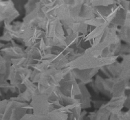
As shown in Table 1, the morphologies indicate that BiOX are 2D nanosheets or 3D hierarchical structures with 2D nanoflakes. In addition, BiOX nanocrystals also were reported by Kaskel.42 The size of BiOX nanocrystals can be controlled by changing the size of the micelles. BiOCl, BiOBr and BiOI nanocrystals were synthesized in the ranges of 3–22 nm (diameter), 5.5–22 nm and 4–18 nm, respectively. In addition to BiOX nanocrystals, another special morphology was nanobelts. By changing the reaction temperature (160–180 °C), reaction time (>12 h) and pH value (pH = 8), BiOCl nanobelts were prepared from Bi(NO3)3·5H2O and CTAC. But the exposed dominant facet of BiOCl nanobelts was the {001} facet which is in agreement with BiOCl nanosheets.67 It implies that the exposed facets of BiOX are {001} facets in general, and the synthesis methods cannot change the exposed facet simply.
2.2 Synthesis mechanisms
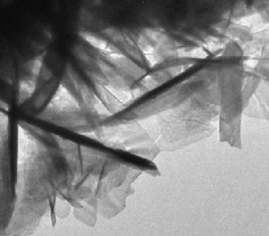
The study of synthesis mechanisms is very important to guide and perfect the synthesis factors. For BiOX, the main morphologies are nanosheets and 3D hierarchical structures. The formation process of nanosheets is very easy. In liquid reaction, the formation is due to the layer structure and low surface energy of the {001} facets of BiOX. In solid reaction, the formation is due to the chemical transport. For example, BiOI nanosheets were synthesized by annealing BiI3.60Fig. 2 shows the original formation process (Fig. 2a) and simulated formation process (Fig. 2b). When the temperature is higher than 350 °C, BiI3 can react with O2 to produce BiOI and iodine vapor. At the same time, BiI3 vapor can be given off by BiI3 sublimation. With the vapours spilling over from BiI3, the pressure made the BiOI nanosheets shell off from BiI3.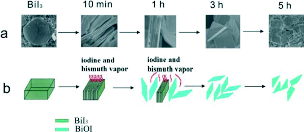 | ||
| Fig. 2 Illustration of formation mechanism of BiOI SCNs: (a) original formation process; (b) simulated formation process.60 Reprinted with permission from Royal Society of Chemistry. | ||
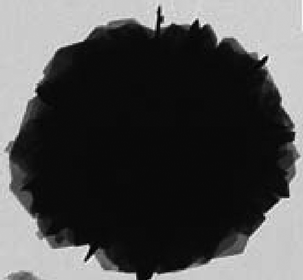
The formation process of 3D hierarchical structures is relatively complex. The main processes include self-assembly and the Tyndall effect.53Fig. 3 shows the formation process of the BiOBr hollow microspheres. 1-Hexadecyl-3-methylimidazolium bromide ([C16Mim]Br) ionic liquid not only gives rise to colloidal mini-emulsions, but also acts as the Br source. Due to the Tyndall effect, the reaction takes place at its phase interface with the mini-emulsion rather than in the emulsion itself. So, the small BiOBr nanosheets can form hollow microspheres via self-assembly.
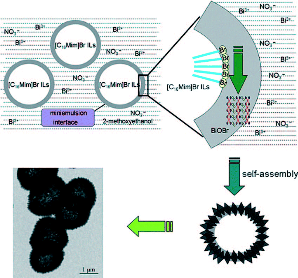 | ||
| Fig. 3 Schematic formation process of BiOBr hollow microspheres by the mini-emulsion mediated solvothermal route.53 Reprinted with permission from Wiley-VCH. | ||
3. Photocatalytic performance without modification
3.1 Photocatalytic activity
Since 2008, BiOX have been widely used as photocatalysts. In general, BiOCl displays higher photocatalytic activity for dyes (RhB, MO, MB, etc.) and phenol degradation under UV light irradiation.68 On the other hand, under visible light irradiation, BiOCl also can effectively remove dyes by dye sensitization pathways. BiOI can absorb more visible light than BiOCl and BiOBr. So, BiOI shows higher VLD photocatalytic activity than BiOCl and BiOBr. For example, Zhang's group found that the BiOI showed higher photocatalytic activity than BiOBr and BiOCl for degrading methyl orange (MO) organic pollutants.38 Zhang demonstrated the synthesis of flower-like BiOI hierarchical structures which showed higher photocatalytic activities toward three types of dyes and phenol under visible light irradiation than the BiOI nanoplatelets.59 BiOBr showed the best photocatalytic oxidation and reduction activity under full light spectrum irradiation due to the appropriate band-gap (2.8 eV). So, it can remove more types of organic pollutants, such as dyes, phenol, bacteria, toluene, tetrabromobisphenol A.49–53,69 Until now, only BiOBr was usually reported to photo-degrade biological substances. For instance, Yu found that hierarchical BiOBr microspheres can effectively kill Micrococcus lylae, a positive bacterium, in water under fluorescent light irradiation.50 Huang firstly pointed out that BiOBr can degrade microcystin-LR in water under visible light irradiation.70,713.2 Photocatalytic selectivity
Selectivity also is a very important factor for catalytic processes. Photocatalytic selectivity of alcohols and azo dyes in TiO2 systems has been paid more attention.72–76 However, pure TiO2 shows poor photocatalytic selectivity, as the adsorption selectivity is very low. For obtaining high photocatalytic selectivity, TiO2 is usually modified by fluorine or alkali to enhance the adsorption selectivity. The surface atoms structure (Fig. 1) reveals that the {001} facets of BiOX contain 100% terminal oxygen atoms, and {001} facets are expected to be more negatively charged. So, BiOX nanosheets with dominant exposed {001} facets may show adsorption selectivity for azo dyes and result in high photocatalytic selectivity.In recent work, the photocatalytic selectivity of BiOI was reported. By analyzing the UV-vis absorption spectra during the photocatalytic degradation of RhB with BiOI, it can be found that the characteristic absorption peak of RhB exhibited a marked blue shift (from 554 to 500 nm). It implies that the prevailing PCD path of the RhB is N-de-ethylation. On the other hand, once RhB is adsorbed on the surface of BiOI, a new peak appears at 401.1 eV, and the shift is about 1.8 eV relative to pure RhB. The shift results from the interaction between the {001} facets of BiOI and the N+ group of RhB. Therefore, it can be concluded that BiOI displays sorption selectivity for azo dyes, and results in high photocatalytic selectivity. Furthermore, the photocatalytic selectivity results showed that the degradation rate of MB is close to that of MO. In contrast, the degradation rates of MB are much faster than those of MO for BiOI TF, and the selective photocatalytic ability R (R = kMB/kMO) is 6.9 which is 6 times higher than that of TiO2 TF. It implies that BiOI with {001} facets exposed can display highly selective photocatalysis.
3.3 Photocatalytic stability
Besides good photocatalytic activity and photocatalytic selectivity, photocatalysts also should display excellent photocatalytic stability during the photocatalytic reaction. It is a very important factor for practical applications. The main factors influencing photocatalytic stability include intrinsic structure and the solubility product constant of the photocatalyst, pH value and the properties of the substrate. The interaction forces between layers of BiOX are van der Waals forces, but there are also covalently bonded layers in the BiOX layer structure. So, BiOX are more stable than other layer photocatalysts such as g-C3N4 whose interaction forces between layers are only van der Waals forces. It had been reported that the solubility product constant of BiOCl is very low at 1.8 × 10⁻³¹, which indicated that BiOX cannot easily dissolve or transform under normal circumstances. However, the pH value and properties of substrates can affect the stability of BiOX. For example, BiOX can dissolve in an acid environment,68 and can react with S2− to transform into Bi2S3.66 Next, the experimental results about the photocatalytic stability of BiOX are exhibited.In 2006, Huang firstly evaluate the stability of BiOCl in the photocatalytic reaction.28 Firstly, the XRD pattern of BiOCl did not change after the photocatalytic reaction. Thereby, the photocatalyst is stable during the reaction and could be repeatedly used. Secondly, it was found that BiOCl again completely decomposed MO in 10 min in two extra cycles, but the photocatalytic activity of TiO2 (P25) decreased. These results indicated that BiOCl was more stable than TiO2 (P25) for the PCD of dyes, and this conclusion was also proved again by Sarwan.68 For, BiOBr, Huo researched the photocatalytic stability by comparing the photocatalytic activity, crystallization and morphology after six cycles.69 The results indicated that BiOBr showed excellent photocatalytic stability and great potential in practical applications. The photocatalytic stability of BiOI powders was also proved by Zhang and the powders acted as stable VLD photocatalysts.59 However, it can be found that all the reported research did not consider the question of photocorrosion releasing traces of Bi which is critical for the environment. So, in our future work, the photocorrosion of BiOX should be taken into account.
Photocatalysts are usually used in a powdered form and it must be separated from the water in a slurry system after the photocatalytic reaction. So, it is inconvenient for many practical applications. Immobilizing the photocatalyst powder as thin films on a solid substrate can overcome it. But, the durability may be a question. Recently, a BiOI thin film (BiOI TF) was prepared via a low temperature chemical vapor transport (CVT) route. The photocatalytic durability results showed that the BiOI TF had a high applied value in photocatalysis for the durability with only a 2% decline in photocatalytic activity after 4 cycles. The higher photocatalytic durability might result from the stronger junction between the BiOI TF and the FTO substrate by CVT immobilization.
3.4 Degradation pathways and intermediates of pollutants when using BiOX
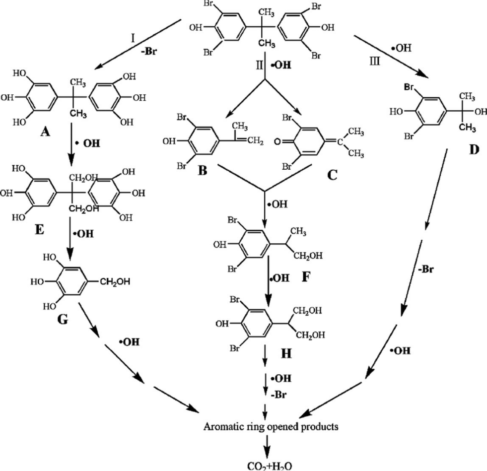
In the reported works, the main study of BiOX photocatalysts focuses on enhancing the photocatalytic activity for environmental remediation. But the degradation pathways of pollutants have been little researched. For gas-phase photocatalysis, only the degradation pathways and intermediates of NO were studied by Zhang's group.54 They found that the amount of NO3− progressively grew near linearly with reaction time, but the amount of NO2− remained almost constant at 0.08 μmol with prolonged illumination. It indicated that the oxidation of NO to NO3− was the major process for the oxidation of gaseous NO over BiOBr microspheres. In addition, it had been reported that the NO2− came from the reaction between NOx and hydroxyl radicals (˙OH) and NO3− came from the reaction between NOx and superoxide radicals (O2˙−). So, Zhang's results also implied that O2˙− was the major reactive oxygen species (ROS).For liquid-phase photocatalysis, the most used substrates are dyes (such as MO, MB and RhB) and phenols. Dye molecules can be decomposed relatively easily and the degradation pathways have been studied deeply. So, many works about BiOX photocatalysis do not show the degradation pathways and intermediates of dyes. On the contrary, the degradation pathways of phenols are complex, and investigating the degradation pathways and intermediates of phenols is very meaningful. In BiOX/UV-vis systems, ˙OH is very important for phenol degradation. Chen proved that the main intermediates of phenol were hydroxyl adducts such as catechol and hydroquinone, which were ˙OH radical-attack products.76 Meng showed that the degradation of tetrabromobisphenol A was started by both hydroxylation and debromination. As shown in Fig. 4, the ˙OH can firstly substitute Br atoms through debromination, leading to the formation of intermediate A. At the same time, the hydroxyl radicals can directly attack the middle C atom, resulting in the formation of intermediates B, C and D. During the photocatalytic process, with the help of ˙OH, the methoxylated compounds can be generated through hydroxylation and demethylation.51
 | ||
| Fig. 4 Proposed TBBPA degradation pathway.51 Reprinted with permission from Elsevier. | ||
In addition, Microcystins-LR produced in cyanobacteria blooms is a very hazardous pollutant which has caused sickness in both humans and animals. The World Health Organization has identified Microcystins-LR as strongly hepatotoxic. Recently, Huang reported the degradation pathways and intermediates of Microcystins-LR in BiOBr/vis systems.70 Isotope labeling techniques indicated that the decarboxylation process is mediated by BiOBr. Furthermore, the oxidative decarboxylation is not always initiated by the ˙OH attack proposed mechanism, whereas it is more likely to be caused by a direct interaction between photoinduced holes of BiOBr and free carboxyl groups of MC-LR.
4. Enhanced VLD photocatalytic activity with modification
Because the three crucial steps (solar light harvesting, charge separation and transportation, and the catalytic reduction and oxidation reactions) for photocatalytic reactions are not efficient enough, although BiOX shows excellent photocatalytic activity for environmental remediation, the overall photocatalytic efficiency is still low and far from practical application under sunlight irradiation. In order to enhance the VLD photocatalytic activity of BiOX, many modification methods, which had been applied in TiO2 systems, have been used to enhance the solar light harvesting and charge separation. As shown in Table 2, these methods include cocatalyst use, doping, coupling, sensitization, graphene use, making defects and so on.77–151 They have successfully improved the VLD photocatalytic activity of BiOX. The details are shown following.| Example | Synthesis method | Best ratio | Light | Photocatalytic activity | Ref. | |
|---|---|---|---|---|---|---|
| a D: decomposition ratio; K: rate constant. | ||||||
| Cocatalyst | Bi–BiOCl | Photoreduction | 5 min | UV light | MO; K: 5.0 times that of BiOCl | 77 |
| Bi–BiOI | Solvothermal | 12.5% Bi | Xenon lamp | Bisphenol A; K: 50 times that of BiOI | 78 | |
| Ag–BiOI | Photodeposition | 4.5% Ag | λ > 420 nm | E. coli; D: about 3.0 times that of BiOI | 79 | |
| Photodeposition | 0.6% Ag | λ > 420 nm | Acid orange II; K: 4.0 times that of BiOI; MO; K: 4.0 times that of BiOI; RhB; K: 3.4 times that of BiOI | 80 | ||
| Pt–BiOI | Photodeposited | 0.2% Pt | λ > 420 nm | Orange II; D: 2.0 times that of BiOI | 81 | |
| MnOx–BiOI | Photodeposited | No | λ > 420 nm | RhB; D: MnOx–BiOI > Pt–BiOI > BiOI | 82 | |
| Doping | Self doping of BiOI | Solvothermal | BiOI1.5 | λ > 420 nm | MO; D: was about 1.5 times that of BiOI | 83 |
| I–BiOCl | Precipitate at 80 °C | No | λ > 420 nm | RhB; D: 5.0 times that of Bi2WO6 | 84 | |
| C–BiOCl | Wet-chemical | 0.4 PAM | λ > 350 nm | MO; D: 2.1 times that of BiOCl | 85 | |
| C, N–BiOCl | Molecular precursor | No | λ > 420 nm | RhB; D: 5.0 times that of BiOCl | 86 | |
| Mn–BiOCl | Hydrolysis | No | Visible | MG; D: 1.5 times that of BiOCl | 87 | |
| Fe–BiOBr | Solvothermal | No | LED lamp | RhB; K: 4.4 times that of BiOBr | 88 | |
| Ti–BiOBr | Self-assemble | Ti0.22BiO1.48Br | λ > 400 nm | RhB; K: 1.6 times that of BiOBr | 89 | |
| Coupling | Bi2S3–BiOCl | Ion exchange | 4.7 nm Bi2S3 | λ > 400 nm | 2,4-DCP; K: 13.4 times that of N-P25 | 90 |
| Ion exchange | No | λ > 400 nm | RhB; D: 2.2 times that of BiOCl, and 11.8 times that of TiO2 | 91 | ||
| NaBiO3–BiOCl | Precipitate at room temperature | 7.1% NaBiO3 | λ > 400 nm | RhB; K: 3.1 times that of BiOCl | 92 | |
| Fe3O4–BiOCl | Precipitate at 80 °C | No | λ > 420 nm | RhB; D: same | 93 | |
| Bi2O3–BiOCl | Chemical etching | 15% Bi2O3 | λ > 420 nm | 1,4-Terephthalic acid; K: 47.6 times that of BiOCl | 94 | |
| BiVO4–BiOCl | Precipitate at 80 °C | 70% BiVO4 | λ > 420 nm | MO; K: 8.4 times that of BiOCl, and 15.6 times that of BiVO4. | 95 | |
| WO3–BiOCl | Precipitate at room temperature | 10% WO3 | λ > 420 nm | RhB; K: 48 times that of BiOCl | 96 | |
| Bi3O4Cl–BiOCl | Solid state reaction | 53% Bi3O4Cl | λ > 420 nm | 2-Propanol; K: 6.6 times that of Bi3O4Cl, and 2.1 times that of P25 | 97 | |
| BOB–BiOCl | Hydrothermal | 20% BOB | λ > 420 nm | RhB; K: 2.3 times that of BiOCl, and 10.3 times that of P25 | 98 | |
| PANI–BiOCl | Chemisorptions | 7 wt.% PANI | λ > 420 nm | MO; K: about 15 times that of BiOCl | 99 | |
| ZnFe2O4–BiOBr | Ultrasound deposition | 10% ZnFe2O4 | Visible | RhB; K: 2.8 times that of BiOBr, and 16.8 times that of P25 | 100 | |
| Bi2WO6–BiOBr | Hydrothermal | No | LED lamp | RhB; D: 3.3 times that of Bi2WO6, and 1.6 times that of BiOBr | 101 | |
| g-C3N4–BiOBr | Deposition | 50% g-C3N4 | λ > 420 nm | RhB; K: 4.9 times that of BiOBr, and 17.2 times that of g-C3N4 | 102 | |
| Deposition | 50% g-C3N4 | λ > 420 nm | RhB; D: 2.7 times that of BiOBr, and 6.3 times that of g-C3N4 | 103 | ||
| Deposition | 3% g-C3N4 | λ > 400 nm | RhB; D: 2.2 times that of BiOBr | 104 | ||
| AgBr/BiOBr | Hydrothermal | No | Visible | Safranin T; D: 2.4 times that of BiOBr or AgBr | 105 | |
| Co-precipitation | 0.2% AgBr | λ > 400 nm | RhB; 1.3 times that of BiOBr; 13.2 times that of P25 | 106 | ||
| Bi2S3–BiOI | Ion exchange | 4% Bi2S3 | λ > 420 nm | MO; K: 8.1 times that of BiOI | 107 | |
| Ag3PO4/BiOI | Deposition | 30% Ag3PO4 | λ > 420 nm | MB; K: 9.5 times that of BiOI | 108 | |
| g-C3N4–BiOI | Deposition | 12.5% g-C3N4 | Tungsten light lamp | MB; K: 4.2 times g-C3N4; and 5.3 times that of BiOI | 109 | |
| Bi4Ti3O12–BiOI | Electrospinning | 20 cycles | λ > 420 nm | RhB; K: 9.7 times that of BiOI | 110 | |
| ZnWO4–BiOI | Chemical bath | Zn/Bi = 2![[thin space (1/6-em)]](https://www.rsc.org/images/entities/char_2009.gif) :1 :1 |
λ > 420 nm | MO; K: 7.1 times that of BiOI, 83.4 times that of ZnWO4 | 111 | |
| (BiO)2CO3–BiOI | Etching | No | λ > 420 nm | MO; K: 11.4 times that of BiOI, 18.9 times that of (BiO)2CO3 | 112 | |
| Bi2WO6–BiOI | Deposition | 13.2 wt% Bi2WO6 | λ > 400 nm | X3B; K: 6.1 times that of Bi2WO6, 5.2 times that of BiOI, and 4.3 times that of P25; toluene; K: 5.9 times that of Bi2WO6, 8.9 times that of BiOI, and 7.8 times that of P25 | 113 | |
| BiPO4–BiOI | Deposition–precipitation | 60% BiPO4 | λ > 400 nm | MO; K: 31.4 times that of BiPO4, 14.1 times that of BiOI | 114 | |
| Bi2O3–BiOI | Chemical etching | 80% Bi2O3 | λ > 400 nm | Phenol; K: 1.4 times that of BiOI, 3.88 times that of Bi2O3 | 115 | |
| ZnO–BiOI | Chemical bath | 50% ZnO | λ > 420 nm | MO; K: 19.8 times that of BiOI, 129.0 times that of ZnO | 116 | |
| ZnSn(OH)6–BiOI | Deposition | 19.7% ZnSn(OH)6 | λ > 400 nm | Phenol; K: 13.5 times that of ZnSn(OH)6 , and 2.8 times that of BiOI | 117 | |
| TiO2–BiOI | Chemical bath | 50% TiO2 | λ > 420 nm | MO; K: 928.0 times that of BiOI, 339.6 times that of TiO2 | 118 | |
| Impregnating-hydroxylation | No | λ > 420 nm | MO; K: 3.0 times that of BiOI | 119 | ||
| AgI–BiOI | Chemical bath | 20% AgI | λ > 400 nm | Phenol; K: 3.4 times that of BiOI, | 120 | |
| Ion exchange | 70.4% AgI | λ > 420 nm | RhB; K: 7.8 and 3.0 times that of bare BiOI and AgI; phenol; K: 2.9 and 14.2 times that of bare BiOI and AgI | 121 | ||
| Ion exchange | AgI 16 nm | λ > 420 nm | 2,4-Dichlorophenol; D: 3.1 times that of BiOI | 122 | ||
| Ion exchange | 40% AgI | λ > 420 nm | MB; K: 9.4 times that of BiOI | 123 | ||
| BiOCl–BiOI | Hydrothermal | 20% BiOCl | λ > 400 nm | RhB; D: about 2.5 times that of BiOCl, about 20.0 times that of BiOI | 124 | |
| Solvothermal | 10% BiOCl | λ > 400 nm | Bisphenol-A; K: 4.3 times that of BiOI, and 20.5 times that of P25 | 125 | ||
| Deposition | 75% BiOCl | λ > 400 nm | NO; K: 4.2 times that of BiOI, 22.0 times that of BiOCl, and 2.9 times that of C-TiO2 | 126 | ||
| BiOBr–BiOI | Deposition | 60% BiOBr | λ > 420 nm | MO; D: about 2.0 times that of BiOCl or BiOBr | 127 | |
| Chemical etching | 40% BiOBr | λ > 420 nm | MO; K: 14.3 times that of BiOBr, 9.8 times that of BiOBr | 128 | ||
| BiOCl–BiOBr | Solvothermal | No | λ > 400 nm | RhB; D: 1.4 times that of BiOBr, 1.5 times that of BiOCl, 19.8 times that of and P25 | 129 | |
| ZnTiO3–BiOI | Deposition | 50% ZnTiO3 | λ > 400 nm | R6G; K: about 10 times that of BiOI or ZnTiO3 | 130 | |
| Graphene | Graphene–BiOCl | Solvothermal | No | UV | Toluene; D: GO-BiOCl > BiOCl | 131 |
| Solvothermal | 0.73% GO | λ > 400 nm | RhB; K: 2.5 times that of BiOCl | 132 | ||
| Graphene–BiOBr | Solvothermal | No | λ > 420 nm | RhB; K: 3.2 times that of BiOBr | 133 | |
| Solvothermal | 2% GO | λ > 420 nm | NO; K: 1.7 times that of BiOBr | 134 | ||
| Solvothermal | 1% GO | λ > 400 nm | Nitroblue tetrazolium; D: about 7.5 times that of BiOBr | 135 | ||
| Hydrothermal | 6% GO | λ > 400 nm | Srh640; D: 1.7 times that of BiOBr | 136 | ||
| Graphene–BiOI | Hydrothermal | No | λ > 420 nm | MO; K: 2.1 times that of BiOI | 137 | |
| Surface plasmon resonance | Ag/BiOBrxI1−x | Reduction with HCOONa | X = 0.75 | Fluorescent lamp | RhB; K: 1.9 times that of Ag-BiOI | 138 |
| Ag/AgCl/BiOCl | Chemical bath | No | λ > 400 nm | RhB; D: about 1.6 times that of BiOCl | 139 | |
| Ag/AgBr/BiOBr | Ion exchange | No | λ > 400 nm | MO; K: 16.5 times that of Ag/AgBr, 56.6 times that of N-TiO2 | 140 | |
| Solvothermal | No | λ > 400 nm | RhB; K: 5.2 times that of AgBr/BiOBr. | 141 | ||
| Microwave-assisted solvothermal | No | λ > 400 nm | p-Nitrophenol; K: 5.4 times that of AgBr, and 2.0 times that of BiOBr | 142 | ||
| Ag/AgI/BiOI | Ion-exchange | 6.0% Ag | λ > 420 nm | MO; K: 6.7 times that of BiOI, 10.2 times that of AgI | 143 | |
| Microwave-assisted solvothermal | No | λ > 420 nm | MB; D: 1.2 times that of BiOI, 1.5 times that of Ag/AgI OPN; D: 1.2 times that of BiOI, 2.0 times that of Ag/AgI | 144 | ||
| Ag/AgX/BiOX (X = Cl, Br) | Chemical bath | No | λ > 400 nm | RhB; K: Ag/AgCl/BiOCl was 59 times that of BiOCl and 12 times that of Ag/AgCl, Ag/AgBr/BiOBr was 11 times that of BiOBr and 7 times that of Ag/AgBr | 145 | |
| Solid solutions | BiOCl(1−x)Brx | Hydrothermal | X = 0.5 | λ > 400 nm | RhB; D: about 2.0 times that of BiOCl or BiOBr | 146 |
| BiOBr(1−x)Ix | Soft chemical | X = 0.75 | λ > 420 nm | MO; K: 6.8 times that of BiOBr, 3.9 times that of BiOI | 147 | |
| BiOCl(1−x)Ix | Soft chemical | X = 0.25 | λ > 400 nm | RhB; D: about 1.3 times that of BiOI; and 1.8 times that of BiOCl | 148 | |
| Defects | Black BiOCl | Photosynthesis | No | λ > 400 nm | RhB; K: 20.3 times that of BiOCl | 149 |
| Ultrathin BiOCl | Hydrothermal | No | λ > 420 nm | RhB; D: about 5 times that of BiOCl | 150 | |
| Sensitization | Bin(Tu)xCl3n–BiOCl | Hydrolysis | No | λ > 420 nm | RhB; K: 27.1 times that of BiOCl | 151 |
| CuPc–BiOCl | Chemical adsorption | No | λ > 620 nm | RhB; D: 3.3 times that of BiOCl | 152 | |
| λ > 410 nm | H2 evolution; D: 3.9 times that of BiOCl, 2.7 times that of 3 wt% Pt/BiOCl | |||||
4.1 Cocatalyst
Cocatalysts loaded on the photocatalysts can act as active sites/reaction sites, provide trapping sites for the photogenerated charges and promote the charge separation which can result in enhanced quantum efficiency.82,153 So, for semiconductor-based photocatalytic systems, an appropriate cocatalyst on the photocatalysts can intensely enhance the photocatalytic activity for environmental remediation. The nature of the loaded cocatalysts is very important. In general, cocatalysts can be divided into deriving-electron types (Ag, Pt, Au) and deriving-hole types (PbO2, MnOx).82,153 It has been reported that a deriving-electron type cocatalyst can enhance the separation efficiency of the photoinduced carriers of BiOX, and then increase the photocatalytic activity.78–81 These findings suggest cocatalyst use is a feasible strategy for developing highly efficient modified BiOX photocatalysts for degrading pollutants. Additionally, it must be pointed out that photo-induced holes are the main active species of BiOX photocatalysts for degrading pollutants. So, deriving-hole type cocatalysts may be more effective in enhancing the separation efficiency of the photoinduced carriers of BiOX. Recently, we prepared MnOx–BiOI photocatalysts by photo-deposition and used them to study the selectivity of the cocatalyst (Fig. 5).82 The PCD results showed that MnOx–BiOI exhibited higher VLD photocatalytic activity than BiOI and Pt–BiOI. And BiOI is selective with a deriving-hole type cocatalyst in enhancing the photocatalytic activity.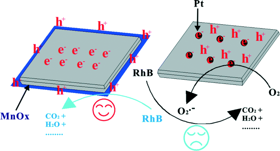 | ||
| Fig. 5 The mechanism of cocatalyst selectivity of BiOI under visible light irradiation (λ ≥ 420 nm).82 Reprinted with permission from Royal Society of Chemistry. | ||
4.2 Doping
The influence of impurity ions doping on the photocatalytic properties of the photocatalyst is another research area of photocatalyst modification. The improved trapping of electrons to inhibit electron–hole recombination and decreased band gap to enhance visible light harvesting are the benefits of doping. It has been reported that Mn, C, N or I doped BiOCl exhibited an obvious red shift compared to the pure BiOCl, and resulted in enhanced VLD photocatalytic activity.84–87 This indicates that the doping can effectively extend the light adsorption edge into the visible light region. For proving that the visible light harvesting ability and the separation efficiency of photoinduced electron–hole pairs is enhanced by doping of BiOX, Zhang used surface photovoltage spectroscopy (SPS) and transient photovoltage (TPV) measurements to detect the charge transfer in self-doped BiOI (BiOI1.5). The increased intensity of the SPS signal on BiOI1.5 indicated that the generation of electron–hole pairs can be improved in BiOI1.5 because of its enhanced visible light harvesting ability. The increased intensity of the TPV signal on BiOI1.5 indicated that it can be more easily excited than BiOI and the photoinduced electron–hole of BiOI1.5 can be more easily separated than in BiOI. So, BiOI1.5 displayed higher VLD photocatalytic activity than pure BiOI.83 The doping mechanism of BiOX is similar to that of TiO2 systems. As shown in Fig. 6, the enhanced degradation activity of BiOCl was due to C-doping which can form impurity energy levels above the VB of BiOCl. The impurity energy levels can cause the shifting of the absorption edge to higher wavelengths and increases the lifetime of charge carriers. Thus, the photocatalytic activity would be improved by both the inhibition of recombination of photo-induced charge carriers and the effective usage of light source.85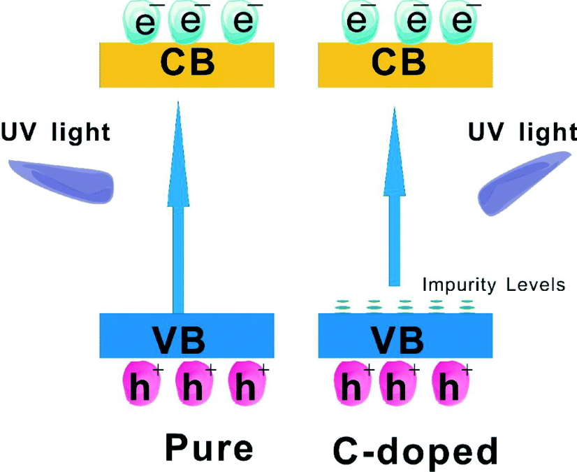 | ||
| Fig. 6 Schematic diagram showing the energy band structure and electron–hole pair separation in pure BiOCl and C-doped BiOCl samples.85 Reprinted with permission from Elsevier. | ||
4.3 Coupling
Semiconductor combination photocatalysts, which construct a heterojunction interface between two types of semiconductor photocatalysts with matching energy band gaps, have been becoming the most important way to increase the efficiency of a photocatalytic process by enhancing the photogenerated charge carriers separation and extending the energy range of photoexcitation for the system, thus achieving better efficiency for environmental remediation. Generally, the coupling of two photocatalysts does not show selectivity.90–130 In recent work, Zan found that the interaction between BiOBr and g-C3N4 is a kind of facet coupling between BiOBr-{001} and g-C3N4-{002}. The facet coupling can result in photoinduced charge transfer between BiOBr and g-C3N4 and enhance the VLD photocatalytic activity for dye degradation. This research gives a possible explanation for the enhanced photocatalytic activity of inorganic–organic composite photocatalysts.1034.4 Graphene
Graphene is a new carbon material with a monolayer of sp2-hybridized carbon atoms packed into a two-dimensional honeycomb structure. Because of graphene's superior electron mobility and high conductivity, it has generated great interest in making various functional composite materials, and graphene hybrids, with metal oxides, metals, and polymers, have been developed for various applications.20 Recently, graphene-based semiconductor photocatalysts have attracted extensive attention because of their usefulness in photocatalysis applications. So, for BiOX photocatalysts, modification with graphene also is a research hotspot. Recently, Zeng's group proved that C–Bi chemical coupling enhanced charge separation of photoinduced charges.131,132 On the basis of this advantage, graphene–BiOCl exhibited a significant enhancement in the photocatalytic activity. The same result for graphene–BiOBr was also reported by Ai, Bai, Li and Zhang.133–136 They suggested that the improved photocatalytic activity of the graphene–BiOBr for the more effective charge separations is due to the strong C–Bi chemical bonding between BiOBr and graphene, rather than the light absorption extension in the visible region and higher surface areas. For graphene–BiOI, Fang synthesized reduced graphene oxide decorated BiOI quantum size nanoparticles, and RGO/BiOI nanocomposites showed enhanced photocatalytic activity under visible light. But they did not find C–Bi chemical coupling in the graphene–BiOI system and suggested that the enhanced VLD photocatalytic activity was attributed to improved light absorption and efficient charge separation and transportation.1374.5 Dye sensitization
Sensitization of a wide band-gap semiconductor photocatalyst via chemisorbed or physisorbed photosensitizers can extend the spectrum applications from UV light to the full spectrum for photocatalysts. When the sensitizer is excited under visible light irradiation, the excited-state electrons can readily transfer to the conduction band (CB) of the photocatalyst, and then progress the photocatalysis reaction. Amongst sensitizers, most applications use organometallic complex sensitizers. For example, ruthenium complexes (N719, C101, C102, and [Ru(bpy)3]2+), copper complexes and zinc complexes are all used in photocatalysis reaction.154–158 For example, overall water splitting reaction to H2 and O2 is realized on a copper phthalocyanine (CuPc) sensitized BiOCl composite from RhB solution under simulated solar light irradiation.151 And by CuPc sensitization, the efficiency of H2 evolution was enhanced. However, ruthenium complexes are expensive and difficult to synthesize. Copper and zinc complexes display low efficiencies. Thus, it is very important to discover some new sensitizers.Recently, Zan found that Bin(Tu)xCl3n bismuth complexes can act as new sensitizers. BiOCl nanosheets with inner Bin(Tu)xCl3n can be synthesized by hydrolyzing Bin(Tu)xCl3n and the as-synthesized BiOCl displayed very high visible light (λ > 420 nm) photocatalytic activity (Fig. 7).151 To the best of our knowledge, there have been few reports about photosensitizers existing inside photocatalysts. Most photosensitizers are absorbed on the surface of a photocatalyst. Obviously, the inner sensitization has some advantages. Firstly, it enhances the stability of the photocatalyst. This method avoids the sensitizer breaking off during the photocatalytic process. Secondly, it expands the applied range of the sensitizer. For example, water soluble Bin(Tu)xCl3n can be used in the photocatalytic degradation (PCD) of RhB in aqueous solution.
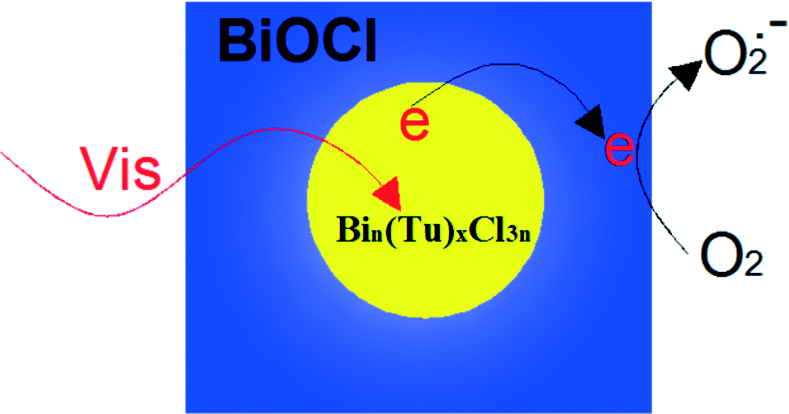 | ||
| Fig. 7 Bin(Tu)xCl3n sensitized the BiOCl and resulted in unusually high visible light photocatalytic activity.151 Reprinted with permission from Royal Society of Chemistry. | ||
It is known that the PCD of dyes can proceed via self-sensitization. For the sensitization of photocatalysis, the PCD efficiency mainly relies on the electron transfer between the dye* and photocatalyst, which is decided by the adsorption of the dye.159,160 Usually, the self-sensitized PCD is relatively inefficient in the case of TiO2.161 However, BiOX exhibited a superior dye self-sensitized PCD efficiency under visible light irradiation. It is due to the more reactive (001) facets with a much higher oxygen atoms density which can enhance the adsorption capability of the dye on BiOX nanosheets.149,162,163 For instance, Chen measured the adsorption capability of RhB on BiOCl nanosheets. And he proved that BiOCl exhibited VLD superior photocatalytic activity for indirect dye sensitization degradation.161 Gondal proved that the RhB molecules can be effectively decomposed via self-sensitization and the dissolved oxygen is very essential during the photodegradation process of BiOBr.163
4.6 Surface plasmon resonance
Surface plasmon resonance (SPR) is the resonant photon-induced oscillation of electrons over noble metals. It can occur when the frequency of exciting light matches the natural frequency of surface electrons oscillating to resist the restoring force of positive nuclei.164 So, SPR can dramatically enhance the absorption of visible light and provides new opportunities for developing VLD photocatalysts. Among these noble metals, Ag shows the best SPR effects. So, much interest has been paid to designing Ag/AgX (X = Cl, Br, I), Ag–TiO2, Ag–ZnO, Ag/AgBr, Ag/AgPO4, Ag/AgBr/TiO2, Ag/AgBr/Bi2WO6, and Ag/AgBr/WO3 composite photocatalysts to improve the VLD photocatalytic activities.165–176 For BiOX, it also has been found that Ag/AgX/BiOX (X = Cl, Br, I) showed enhanced VLD photocatalytic activity for the degradation of pollutants, and it was much higher than Ag/AgX and BiOX.138–145 Furthermore, active species trapping and superoxide radical quantification experiments revealed that metallic Ag played different roles for Ag/AgX/BiOX VLD photocatalysts, SPR for Ag/AgCl/BiOCl, and the Z-scheme bridge for Ag/AgBr/BiOBr.145 The SPR mechanism of Ag/AgCl/BiOCl is shown in Fig. 8. The interaction between Ag NPs and incident visible light with considerable energy could give rise to the collective oscillation of free electrons. Then electrons transfer to the conduction band minimum (CBM) of AgCl and further transfer to the CB of BiOCl. At the end, the electrons react with O2 to produce O2˙−. The photogenerated holes transfer to the AgCl and BiOCl surface to oxidize Cl− ions producing Cl˙ radicals. The Cl˙ radical can oxidize RhB, and hence, Cl˙ is reduced to Cl− ions again.145 On the base of the above photocatalytic mechanism discussion, it can be suggested that metallic Ag plays a very important role in SPR.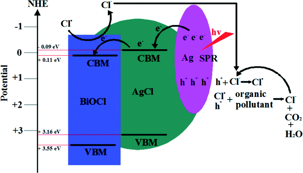 | ||
| Fig. 8 Photocatalytic mechanism scheme of Ag/AgCl/BiOCl under visible light irradiation (λ ≥ 400 nm).145 Reprinted with permission from American Chemical Society. | ||
4.7 Other
In order to enhance the VLD photocatalytic activity, reducing the band gaps so that they can absorb visible light and preventing the recombination of photogenerated carriers so that reduction and/or oxidation reactions can be driven by using the carriers are the underlying goals. Besides the above modification methods, there are some other methods to enhance the VLD photocatalytic activity, such as oxygen vacancy and solid solutions.5. Facet effect
The crystal facet is an important feature of crystalline materials. Different crystal facets have different geometric and electronic structures, exhibiting intrinsic reactivity and surface physical and chemical properties. Therefore, semiconducting photocatalysts with well-defined facets have aroused much research interest due to their intrinsic facet dependent photocatalytic properties.36,152,181–187 Since Yang reported the anatase TiO2 properties with dominant {001} facets,188,189 the facet-dependent photocatalytic activity of anatase TiO2 has been intensively investigated.190–208 Besides TiO2, the facet effects of many other photocatalysts, such as ZnO,209 Cu2O,210–212 BiVO4,153,184 AgBr,185 and AgPO4,187,213 also were researched and stirring results were reported. For BiOX, the layer structure results in a basic morphology and exposed facet: nanosheets with {001} facets exposed, and other facets of BiOX are very difficult to expose. So, in 2011, the facets effect of BiOX was reported for the first time. Recently, our group and Zhang's group researched in detail the facets effect of BiOCl.44,60,214,215 And then, the facets effects of BiOBr and BiOI were reported.216–219 But, the facet effect research for BiOX is still very limited.5.1 {001} facet
:Tu in the molecular precursors, the {001} facets percentage of BiOCl NSs can be controlled from 71% to 87%. A positive correlation relationship between the percentage of {001} facets and the photoactivity of BiOCl was found (Table 3). Furthermore, the reason for the high photoactivity of {001} facets was studied using electron paramagnetic resonance (EPR) and PL techniques. It was observed that the intensity of both the EPR signal arising from UV light-induced oxygen vacancies and a new PL band is proportional to the percentage of {001} facets. High oxygen atom density in {001} facets is considered as the fundamental cause for the increase of the UV-induced oxygen vacancies in the crystal lattice, that enhances, consequently, the photoactivity of BiOCl.
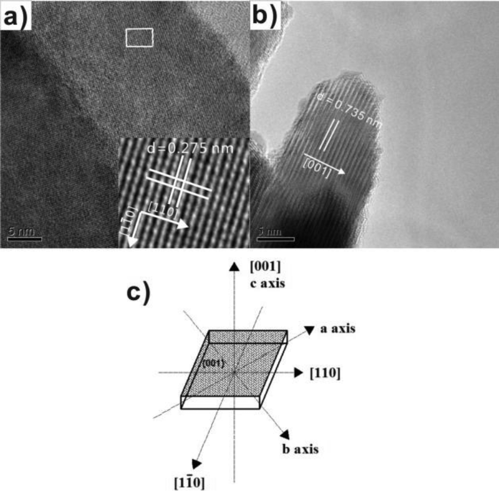 | ||
| Fig. 9 (a) Top view HRTEM images of BiOCl NS-3; (b) side view HRTEM image of BiOCl NS-3; and (c) schematic structure of a single BiOCl NS.44 Reprinted with permission from Royal Society of Chemistry. | ||
| Photocatalyst | BET (m2 g−1) | Thicknessa | Percentage of {001} facets | k (mol L−1 s−1) | (C0 − Ct)/C0b |
|---|---|---|---|---|---|
| a The thickness was measured from FESEM images. b (C0 − Ct)/C0 was obtained at t = 32 min. | |||||
| Aschistic BiOCl | 6.0 | NA | NA | 0.0030 | 9.6% |
| BiOCl NS-1 | 13.9 | 36 nm | ca. 71% | 0.0107 | 33.6% |
| BiOCl NS-2 | 13.8 | 29 nm | ca. 75% | 0.0151 | 48.1% |
| BiOCl NS-3 | 14.3 | 13 nm | ca. 87% | 0.0255 | 81.1% |
Recently, porous BiOCl micro-flowers constructed from ultrathin nanosheets with nearly 100% {001} facets exposed were prepared.216 The authors thought that the exposed {001} facets terminated with a high density of oxygen atoms are not only favorable for the adsorption of the cationic dye RhB but also can accumulate the photogenerated electrons injected from excited RhB. These electrons can be captured by O2 and transformed to reactive oxygen species, which possess strong photooxidative ability to degrade the dye pollutants directly.
5.2 {010} facet
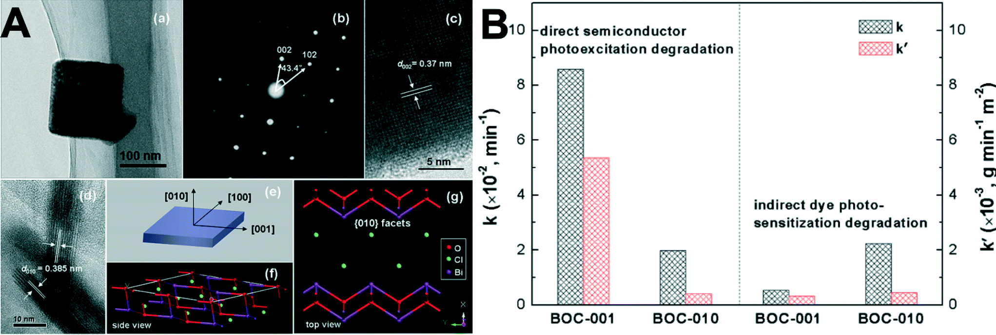 | ||
| Fig. 10 (A): (a) TEM image, (b) SAED pattern, and (c, d) HRTEM images of the BOC-010 SCNSs. (e) Schematic illustration of the crystal orientation of the nanosheet. (f, g) Atomic structure of the {010} facets: (f) side view; (g) top view. (B): Comparison of the apparent reaction rate constants for photocatalytic degradation of MO over the BOC SCNSs under (left) UV (λ = 254 nm) and (right) visible-light (λ > 420 nm) irradiation.214 Reprinted with permission from American Chemical Society. | ||
5.3 Advice on facets confirmation for BiOX
Facets confirmation is the basic premise of the research about the facet effect. In general, for confirming the dominant exposed facet, transmission electron microscope (TEM) images and the corresponding selected-area electron diffraction (SAED) pattern, or high resolution TEM images and the corresponding fast-Fourier transform (FFT) pattern are needed. However, because the theoretical value of the angle between the (102) and (002) facets is very close to that of between the (200) and (110) facets, the facets confirmation of BiOX should be done very carefully. On the basis of the above observation and the symmetries of tetragonal BiOX, the dominant exposed facets of BiOX samples cannot be identified by the angle easily.Table 4 shows the theoretical d values of (110), (200), (102) and (200), and the theoretical angles between (110) and (200), and (102) and (200) of BiOX. It can be found that the theoretical angles between (110) and (200) are very close to that of (102) and (200), especially for BiOBr. But, the theoretical d values of (110), (200), (102) and (200) of BiOX are different. The d(002) of BiOX are much higher than that of (110), (200) and (102). So, if the SAED or FFT pattern has scale-plate, the d values of the diffraction spots can be indexed and the exposed facets can be confirmed. It is a pity that many reported works did not display the scale-plate of the SAED or FFT pattern.
| a = b | c | 110 | 200 | 102 | 002 | ||
|---|---|---|---|---|---|---|---|
| BiOCl | 0.3883 nm | 0.7347 nm | d value | 0.275 nm | 0.194 nm | 0.267 nm | 0.367 nm |
| Angle | 45.0° | 43.4° | |||||
| BiOBr | 0.3915 nm | 0.8076 nm | d value | 0.277 nm | 0.196 nm | 0.281 nm | 0.404 nm |
| Angle | 45.0° | 45.9° | |||||
| BiOI | 0.3984 nm | 0.9128 nm | d value | 0.282 nm | 0.199 nm | 0.300 nm | 0.456 nm |
| Angle | 45.0° | 48.7° | |||||
6. Photocatalytic mechanisms
6.1 Band structures
Because band structure results in selective active species generation which can degrade pollutants, the photocatalytic mechanism for environmental remediation is mainly dependent on band structures. It has been reported that the UV-vis absorption edges of BiOX powders increase with the X atomic number increasing. The absorption edges of BiOCl, BiOBr and BiOI are 370, 440 and 670 nm in near-UV, UV-visible and visible light regions, respectively. So, the colors of BiOCl, BiOBr, and BiOI are white, light yellow, and red, respectively.The band gaps are also determined using the following equation:
| αhν = A(hν − Eg)n/2 | (1) |
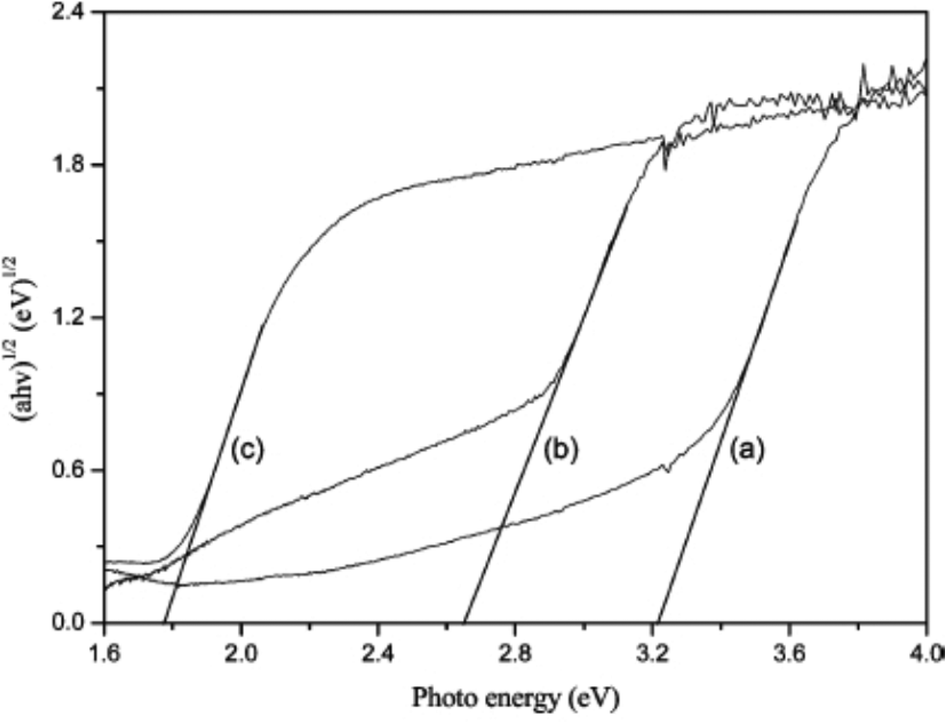 | ||
| Fig. 11 Plots of (αhv)1/2vs. photon energy (hv) for BiOX (X = Cl, Br, I) photocatalysts. (a) BiOCl, (b) BiOBr, and (c) BiOI.38 Reprinted with permission from American Chemical Society. | ||
The conduction band minimum (CBM) and valence band maximum (VBM) potentials of BiOX photocatalysts at the point of zero charge can be calculated according to the empirical equations:
| ECBM = χ − Ec − 0.5Eg | (2) |
| EVBM = ECBM + Eg | (3) |
| χ/eV | E g/eV | E CBM/eV | E VBM/eV | |
|---|---|---|---|---|
| a Note: the relevant data were selected from the CRC handbook of chemistry and physics (87th edn, 2006–2007). | ||||
| BiOCl | 6.33 | 3.22 | 0.22 | 3.44 |
| BiOBr | 6.17 | 2.64 | 0.35 | 2.99 |
| BiOI | 5.99 | 1.79 | 0.60 | 2.39 |
In addition, a first-principles study on the structural, electronic and optical properties of BiOX crystals indicated that (a) the valance band maximum is mainly contributed to by O 2p and X np states and the Bi 6p states dominate the conduction band minimum; (b) the calculated absorption edges of the absorption coefficients I(ψ) for BiOCl, BiOBr and BiOI crystals are 355, 448 and 645 nm, respectively, which agree well with the reported experimental results of 370, 440 and 670 nm.28–33
6.2 Active species
Active species are necessary conditions for photocatalytic environmental remediation. In previous works, EPR technology and trapping experiments were used to test the active species of BiOX during the photocatalytic reaction, and then they can be used to explain the photocatalytic mechanism. In general, for detecting the active species during photocatalytic reactivity, ˙OH, O2˙−, and holes (h+) were investigated by adding 1.0 mM isopropyl alcohol (IPA, a quencher of ˙OH),220–222p-benzoquinone (BQ, a quencher of O2˙−),223,224 and triethanolamine (TEOA, a quencher of h+),149 respectively. Nitroblue tetrazolium (NBT, 2.5 × 10⁻⁵ mol L−1, exhibiting an absorption maximum at 259 nm) was used to determine the amount of O2˙− generating from all photocatalytic systems. The production of O2˙− was quantitatively analyzed by detecting the concentration of NBT. Terephthalic acid (TA) (5 × 10⁻⁴ mol L−1) and NaOH (2 × 10⁻³ mol L−1) solution was used to determine the amount of ˙OH.For example, Fig. 12 shows the trapping experiments for BiOI during the photocatalytic reaction under Xenon lamp irradiation. It can be seen that the photocatalytic degradation of RhB was not affected by the addition of 1 mM IPA (a quencher of ˙OH). On the contrary, the photocatalytic degradation of RhB decreased obviously with the addition BQ (a quencher of O2˙−) and TEOA (a quencher of h+). Therefore, it can be concluded that O2˙− and h+ are the main active species rather than ˙OH under Xenon lamp irradiation. In addition, a colorless molecular probe, nitroblue tetrazolium (NBT) was chosen to quantify the O2˙− concentration (NBT transformation percentage, Fig. 12b). It also proved the generation of O2˙− under Xenon lamp irradiation. It is in agreement with the results of trapping experiments.
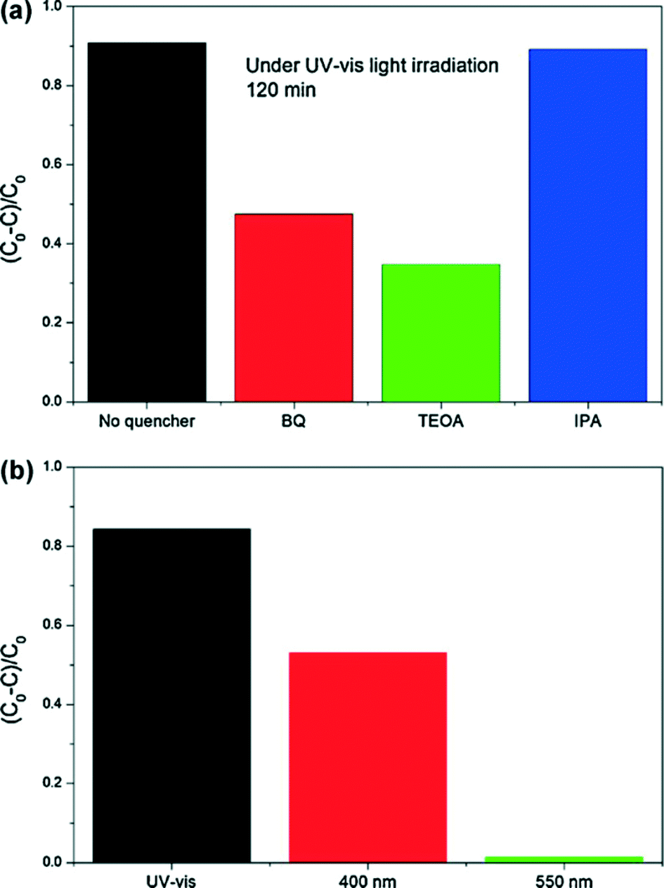 | ||
| Fig. 12 Photocatalytic mechanism for BiOI TF: (a) trapping experiments of active species during the photocatalytic reaction with 120 min Xenon lamp irradiation; and (b) transformation percentage of NBT concentration under Xenon lamp, 400 nm and 550 nm monochromatic light irradiation.215 Reprinted with permission from Elsevier. | ||
In the reported paper, about active species, it can be found that photogenerated holes and O2˙− are the main species of all BiOX photocatalysts for environmental remediation under Xe lamp irradiation. Because the standard redox potential of Bi(V)/Bi(III) (+1.59 V) is more negative than that of ˙OH/−OH (+1.99 V),225 there is no ˙OH production from photogenerated holes for BiOX photocatalysts. But, why can a few ˙OH be detected by EPR technology in the degradation of phenols? It may be due to the two-electron oxidation pathway of electrons in the CB of BiOX. However, it is very surprising that O2˙− was generated, although the CBM potentials of BiOX are more positive than E0(O2/O2˙− = −0.046 eV vs. NHE). In order to explain the unusual phenomenon, band width mechanism and separated band mechanism are suggested to explain it.
6.3 Band width mechanism: the case of BiOI
Band width mechanism is based on the continuity of the band structure of semiconductors. If the exciting energy is suitable, the photogenerated electrons can reach any position of the CB. As shown in Fig. 13, the CBM and VBM potentials are 0.6 eV and 2.39 eV for BiOI, respectively. Under Xenon lamp irradiation, the low-energy part (irradiation energy is lower than 2.44 eV) cannot result in the photogenerated electrons exciting up to a higher CB potential than E0(O2/O2˙− = −0.046 eV vs. NHE). However, the high-energy part (irradiation energy is higher than 2.44 eV (508 nm)) can result in the photogenerated electrons exciting up to a higher CB potential than E0(O2/O2˙− = −0.046 eV vs. NHE) (eqn (4)). And then, the electrons in the CB of BiOI can react with O2 to produce O2˙− (eqn (5)). Then, O2˙− can react with H+ to produce a few ˙OH (eqn (6)). At the end, holes, O2˙− and ˙OH are consumed to degrade pollutants (eqn (7)).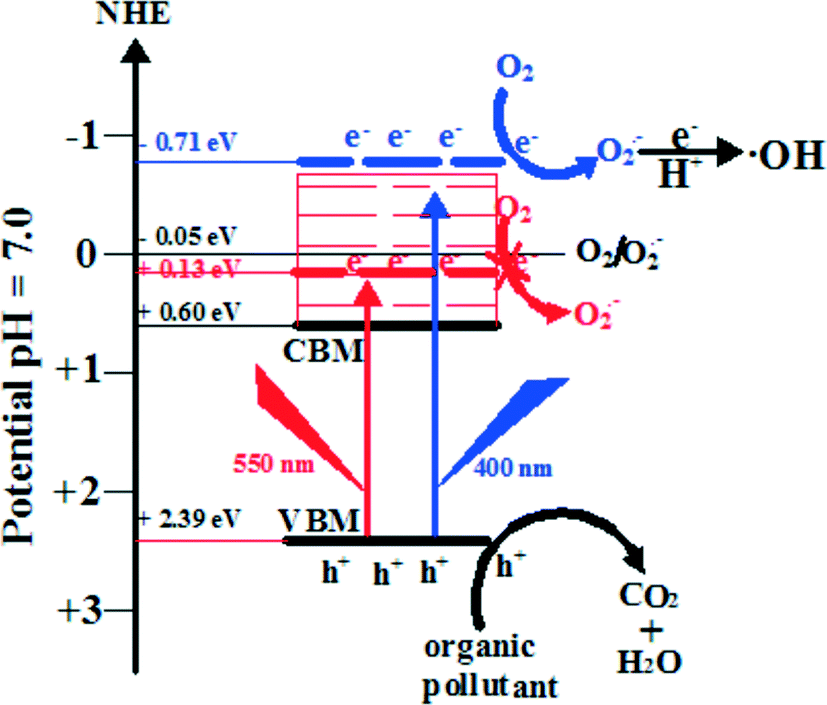 | ||
| Fig. 13 Photocatalytic mechanism scheme of BiOI under Xenon lamp irradiation.215 Reprinted with permission from Elsevier. | ||
For proving the suggested band width photocatalytic mechanism, monochromatic light of wavelength 400 and 550 nm was used to detect O2˙−. It was found that there was O2˙− production under 400 nm light irradiation and no O2˙− under 550 nm light irradiation. These results indicated that the CBM potential of BiOI is not the necessary condition for O2˙− production. At the end, it should be pointed out that a similar band width photocatalytic mechanism also happened for BiOCl and BiOBr.55,149,163 The reason may be due to their same layered structures, and more studies are needed to perfect it.
| BiOX + hν → BiOX (e− + h+) | (4) |
| O2 + e− → O2˙− | (5) |
| O2˙− + e− + 2H+ → 2˙OH | (6) |
| h+ + O2˙− + ˙OH + pollutants → CO2 + H2O | (7) |
6.4 Discrete valence-band mechanism: the case of BiOBr
It had been reported that BiOX may have two possible valence-band structures: two discrete valence bands constructed respectively from O 2p and X np orbitals; or one valence band derived from the hybridization of these orbitals.28–33 Separated valence-band mechanism is based on the discrete valence bands of BiOX. In a recent work, Huang revealed that BiOBr had two separate valence bands (constructed with O 2p and Br 4p orbitals, respectively) rather than a hybridized valence band.71 These two valence bands responded respectively to UV and visible irradiation and displayed complex reactivity. As shown in Fig. 14, the Bi 6p orbitals potential is close to E0(O2/O2˙−); the Br 4p orbitals potential is much higher than E0(H2O/˙OH); and the O 2p orbitals potential is close to E0(H2O/˙OH). So, under visible light irradiation, the photogenerated holes hBr4p+ cannot oxidize H2O to produce ˙OH and photogenerated electrons e− can reduce O2 to produce a few O2˙− due to the band width mechanism. Under UV light irradiation, photogenerated e− and hO2p+ can reduce O2 to produce a few O2˙− and oxidize H2O to produce a few ˙OH due to the band width mechanism. On the other hand, the O 2p orbitals potential is much lower than E0(H2O2/O2˙−), and hO2p+ cannot reduce H2O2 to produce more O2˙−, which has also been proved by EPR data. At the end, it can be found that the band width mechanism is the basis of the discrete valence-band mechanism. And they all can explain the active species trapping experiments and EPR data.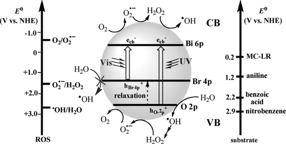 | ||
| Fig. 14 Potentials (versus normal hydrogen electrode, NHE) for the single-electron transfer of H2O and O2 and substrates used in this investigation, with corresponding reactions on the conduction band (CB) and valence band (VB) of activated BiOBr. No assumptions are made concerning the type of charge transfer involved. ROS = reactive oxygen species, MC-LR = Microcystin-LR.71 Reprinted with permission from Wiley-VCH. | ||
7. Summary and future perspectives
In summary, this review article presents an overview of recent studies related to the heterogeneous chemistry and photochemistry of BiOX for efficient photocatalytic degradation removal of pollutants in air, water and biological contaminants. Firstly, advanced synthesis methods provide the expansion of surface area and the special structure of BiOX, which can enhance the photocatalytic performances of BiOX. Secondly, after modification, solar irradiation can provide sufficient energy to initiate photocatalysis on BiOX surfaces; heterogeneous photochemistry of BiOX has the potential to become increasingly important in environmental remediation. Thirdly, studies on the facet effect expanded the surface chemistry factor for pollutants degradation. And, it also can guide the synthetic strategy for highly-active BiOX photocatalysts with active facets exposure. At the end, the photocatalytic mechanism analysis explains the types and the generation pathways of active species during BiOX photocatalysis. Although these studies offer an important basis for our understanding, there remain many questions about BiOX photocatalysis, such as the energy photocatalysis field, synthesis methods for active facets exposure and deeper photocatalytic mechanisms study. These questions can be answered through a combined effort of laboratory studies and theory computations. Some questions and future directions include the following:(1) In general, the morphology of BiOX is 2D nanosheets with {001} facets exposed. Although BiOX nanosheets with {010} facets exposed were synthesized, other morphologies (such as 1D nanorods, 3D nanocubes, etc.) and other facet exposures were reported a little. New synthesis methods should be developed to expose other facets and perfect the facet effects of BiOX photocatalysis. In addition, immobilization technology of BiOX should be studied to improve the practical applications.
(2) To date, most of the reports on BiOX photocatalysts are focused on the decomposition of liquid organic pollutants. BiOX photocatalysis in atmospheric and solid-phase pollutants have been little researched, and they should be enhanced. Furthermore, it can be found that BiOX are rarely used in the energy photocatalysis field, such as water splitting and CO2 photoreduction. It should be extended to utilizing BiOX photocatalysts.
(3) There are some arguments about the photocatalytic mechanisms of BiOX. Theory computations suggested that there should be no reactive oxygen species generated due to the band structures. But EPR technology and trapping experiments had displayed that there are a few ROS generated. So the band width mechanism and discrete valence-band mechanism were used to explain this phenomenon. However, electrochemical impedance spectroscopy indicated that the potential of the conduction band electrons of BiOX is higher than the reduction potential of oxygen and the potential of the valence band holes is lower than the oxidation potential of adsorbed hydroxyl species. Therefore, the formation of ROS is thermodynamically permissible. But, why is the production of ROS so low? More photocatalytic mechanism studies of BiOX should be undertaken.
(4) As the layered crystal structures of BiOX comprise interlacing [Bi2O2] slabs with double halogen slabs, the strong ionic features could result in ion exchange reactions between BiOX and incoming species. For instance, Bi2S3 disk-like networks,226 and Bi2WO6 hollow microspheres227,228 were obtained by this strategy. It indicates that BiOX have wide application, not only can they be used as photocatalysts but they also can be used as hard templates to prepare other photocatalysts with different nanostructures.
Acknowledgements
This work was supported by The Education Department of Henan province Science and Technology Research Projects (no. 14A150021).References
- H. Chen, C. E. Nanayakkara and V. H. Grassian, Chem. Rev., 2012, 112, 5919–5948 CrossRef CAS PubMed.
- C. Chen, W. Ma and J. Zhao, Chem. Soc. Rev., 2010, 39, 4206–4219 RSC.
- I. K. Konstantinou and T. A. Albanis, Appl. Catal., B, 2004, 49, 1–14 CrossRef CAS PubMed.
- A. Kubacka, M. Fernández-García and G. Colón, Chem. Rev., 2012, 112, 1555–1614 CrossRef CAS PubMed.
- Y. Wang, X. Wang and M. Antonietti, Angew. Chem., Int. Ed., 2011, 50, 2–24 CrossRef.
- X. Chen, S. Shen, L. Guo and S. S. Mao, Chem. Rev., 2010, 110, 6503–6570 CrossRef CAS PubMed.
- M. M. Khin, A. S. Nair, V. J. Babu, R. Murugan and S. Ramakrishna, Energy Environ. Sci., 2013, 5, 8075–8109 Search PubMed.
- R. Andreozzi, V. Caprio, I. Ermellino and A. I. Tufano, Ind. Eng. Chem. Res., 1996, 35, 1467–1471 CrossRef CAS.
- A. L. Linsebigler, G. Lu and J. T. Yates Jr, Chem. Rev., 1995, 95, 735–758 CrossRef CAS.
- O. K. Dalymple, E. Stefanakos, M. A. Trotz and D. Y. Goswami, Appl. Catal., B, 2010, 98, 27–38 CrossRef PubMed.
- T. L. Thompson and J. T. Yates Jr, Chem. Rev., 2006, 106, 4428–4453 CrossRef CAS PubMed.
- N. Serpone and A. V. Emeline, J. Phys. Chem. Lett., 2012, 3, 673–677 CrossRef CAS.
- M. R. Hoffmann, S. T. Martin, W. Choi and D. W. Bahnemannt, Chem. Rev., 1995, 95, 69–96 CrossRef CAS.
- S. Linic, P. Christopher and D. B. Ingram, Nat. Mater., 2011, 10, 911–921 CrossRef CAS PubMed.
- Q. Xiang, J. Yu and M. Jaroniec, Chem. Soc. Rev., 2012, 41, 782–796 RSC.
- S. Liu, J. Yu, B. Cheng and M. Jaroniec, Adv. Colloid Interface Sci., 2012, 173, 35–53 CrossRef CAS PubMed.
- J. Reed and G. Ceder, Chem. Rev., 2004, 104, 4513–4534 CrossRef CAS.
- R. Burch, S. Chalker, P. Loader, J. M. Thomas and W. Ueda, Appl. Catal., A, 1992, 82, 77–90 CrossRef CAS.
- N. Kijima, K. Matano, M. Saito, T. Oikawa, T. Konishi, H. Yasuda, T. Sato and Y. Yoshimura, Appl. Catal., A, 2001, 206, 237–244 CrossRef CAS.
- A. M. Kusainova, P. Lightfoot, W. Zhou, S. Y. Stefanovich, A. V. Mosunov and V. A. Dolgikh, Chem. Mater., 2001, 13, 4731–4737 CrossRef CAS.
- Y. Lei, G. Wang, S. Song, W. Fan, M. Pang, J. Tang and H. Zhang, Dalton Trans., 2010, 39, 3273–3278 RSC.
- F. J. Maile, G. Pfaff and P. Reynders, Prog. Org. Coat., 2005, 54, 150–163 CrossRef CAS PubMed.
- K. L. Zhang, C. M. Liu, F. Q. Huang, C. Zheng and W. D. Wang, Appl. Catal., B, 2006, 68, 125–129 CrossRef CAS PubMed.
- W. Huang and Q. Zhu, Comput. Mater. Sci., 2008, 43, 1101–1108 CrossRef CAS PubMed.
- H. Zhang, L. Liu and Z. Zhou, RSC Adv., 2012, 2, 9224–9229 RSC.
- W. Wang, W. Yang, R. Chen, X. Duan, Y. Tian, D. Zeng and B. Shan, Phys. Chem. Chem. Phys., 2012, 14, 2450–2454 RSC.
- X. Zhang, C. Fan, Y. Wang, Y. Wang, Z. Liang and P. Han, Comput. Mater. Sci., 2013, 71, 135–145 CrossRef CAS PubMed.
- L. Zhao, X. Zhang, C. Fan, Z. Liang and P. Han, Phys. B, 2012, 407, 3364–3370 CrossRef CAS PubMed.
- C. Yang, K. Deng, T. Peng and L. Zan, Chem. Eng. Technol., 2011, 34, 1–8 Search PubMed.
- X. Zhao, Z. Li, Y. Chen, L. Shi and Y. Zhu, J. Mol. Catal. A: Chem., 2007, 268, 101–106 CrossRef CAS PubMed.
- L. Zan, W. Fang and S. Wang, Environ. Sci. Technol., 2006, 40, 1681–1685 CrossRef CAS.
- C. Yang, C. Gong, T. Peng, K. Deng and L. Zan, J. Hazard. Mater., 2010, 178, 152–156 CrossRef CAS PubMed.
- H. Cheng, B. Huang and Y. Dai, Nanoscale, 2014, 6, 2009–2026 RSC.
- M. H. Huang and P. H. Lin, Adv. Funct. Mater., 2012, 22, 14–24 CrossRef CAS.
- H. Tong, S. Ouyang, Y. Bi, N. Umezawa, M. Oshikiri and J. Ye, Adv. Mater., 2012, 24, 229–251 CrossRef CAS PubMed.
- Z. Y. Jiang, Q. Kuang, Z. X. Xie and L. S. Zheng, Adv. Funct. Mater., 2010, 20, 3634–3645 CrossRef CAS.
- G. Liu, J. C. Yu, G. Q. Lu and H. M. Cheng, Chem. Commun., 2011, 47, 6763–6783 RSC.
- X. Zhang, Z. Ai, F. Jia and L. Zhang, J. Phys. Chem. C, 2008, 112, 747–753 CAS.
- X. Chang, J. Huang, C. Cheng, Q. Sui, W. Sha, G. Ji, S. Deng and G. Yu, Catal. Commun., 2010, 11, 460–464 CrossRef CAS PubMed.
- H. An, Y. Du, T. Wang, C. Wang, W. Hao and J. Zhang, Rare Met., 2008, 27, 243–250 CrossRef CAS.
- Z. Deng, D. Chen, B. Peng and F. Tang, Cryst. Growth Des., 2008, 8, 2995–3003 CAS.
- J. Henle, P. Simon, A. Frenzel, S. Scholz and S. Kaskel, Chem. Mater., 2007, 19, 366–373 CrossRef CAS.
- S. Peng, L. Li, P. Zhu, Y. Wu, M. Srinivasan, S. G. Mhaisalkar, S. Ramakrishna and Q. Yan, Chem.–Asian J., 2013, 8, 258–268 CrossRef CAS PubMed.
- L. Ye, L. Zan, L. Tian, T. Peng and J. Zhang, Chem. Commun., 2011, 47, 6951–6953 RSC.
- H. Peng, C. K. Chan, S. Meister, X. F. Zhang and Y. Cui, Chem. Mater., 2009, 21, 247–252 CrossRef CAS.
- J. M. Song, C. J. Mao, H. L. Niu, Y. H. Shen and S. Y. Zhang, CrystEngComm, 2010, 12, 3875–3881 RSC.
- C. Shao and Y. Liu, Micro Nano Lett., 2012, 7, 152–154 Search PubMed.
- J. Xiong, G. Cheng, G. F. Li, F. Qin and R. Chen, RSC Adv., 2011, 1, 1542–1552 RSC.
- L. Zhang, X. F. Cao, X. T. Chen and Z. L. Xue, J. Colloid Interface Sci., 2011, 354, 630–636 CrossRef CAS PubMed.
- D. Zhang, M. Wen, B. Jiang, G. Li and J. C. Yu, J. Hazard. Mater., 2012, 212, 104–111 CrossRef PubMed.
- J. Xu, W. Meng, Y. Zhang, L. Li and C. Guo, Appl. Catal., B, 2011, 107, 355–362 CrossRef CAS PubMed.
- Y. Feng, L. Li, J. Li, J. Wang and L. Liu, J. Hazard. Mater., 2011, 192, 538–544 CrossRef CAS PubMed.
- H. Cheng, B. Huang, Z. Wang, X. Qin, X. Zhang and Y. Dai, Chem.–Eur. J., 2011, 17, 8039–8043 CrossRef CAS PubMed.
- Z. Ai, W. Ho, S. Lee and L. Zhang, Environ. Sci. Technol., 2009, 43, 4143–4150 CrossRef CAS.
- Z. Jiang, F. Yang, G. Yang, L. Kong, M. O. Jones, T. Xiao and P. P. Edwards, J. Photochem. Photobiol., A, 2010, 212, 8–13 CrossRef CAS PubMed.
- Y. Wang, K. Deng and L. Zhang, J. Phys. Chem. C, 2011, 115, 14300–14308 CAS.
- J. Xia, S. Yin, H. Li, H. Xu, Y. G. Yan and Q. Zhang, Langmuir, 2011, 27(3), 1200–1206 CrossRef CAS PubMed.
- Y. Li, J. Wang, H. Yao, L. Dang and Z. Li, J. Mol. Catal. A: Chem., 2011, 334, 116–122 CrossRef CAS PubMed.
- X. Xiao and W. D. Zhang, J. Mater. Chem., 2010, 20, 5866–5870 RSC.
- L. Ye, L. Tian, T. Peng and L. Zan, J. Mater. Chem., 2011, 21, 12479–12484 RSC.
- M. Shang, W. Wang and L. Zhang, J. Hazard. Mater., 2009, 167, 803–809 CrossRef CAS PubMed.
- Y. Li, J. Liu, J. Jiang and J. Yu, Dalton Trans., 2011, 40, 6632–6634 RSC.
- S. Wu, J. Fang, X. Hong, K. Hui and Y. Chen, Dalton Trans., 2014, 43, 2611–2619 RSC.
- N. T. Hahn, S. Hoang, J. L. Self and C. B. Mullins, ACS Nano, 2012, 6(9), 7712–7722 CrossRef CAS PubMed.
- M. Liu, L. Zhang, K. Wang and Z. Zheng, CrystEngComm, 2011, 13, 5460–5466 RSC.
- Z. Liu, J. Fang, W. Xu, X. Xu, S. Wu and X. Zhu, Mater. Lett., 2012, 88, 82–85 CrossRef CAS PubMed.
- H. Deng, J. Wang, Q. Peng, X. Wang and Y. Li, Chem.–Eur. J., 2005, 11, 6519–6524 CrossRef CAS PubMed.
- B. Pare, B. Sarwan and S. B. Jonnalagadda, J. Mol. Struct., 2012, 1001, 196–202 CrossRef PubMed.
- Y. Huo, J. Zhang, M. Miao and Y. Jin, Appl. Catal., B, 2012, 111–112, 334–341 CrossRef CAS PubMed.
- Y. Fang, Y. Huang, J. Yang, P. Wang and G. Cheng, Environ. Sci. Technol., 2011, 45, 1593–1600 CrossRef CAS PubMed.
- Y. F. Fang, W. H. Ma, Y. P. Huang and G. W. Cheng, Chem.–Eur. J., 2013, 19, 3224–3229 CrossRef CAS PubMed.
- M. Zhang, C. Chen, W. Ma and J. Zhao, Angew. Chem., Int. Ed., 2008, 47, 9730–9733 CrossRef CAS PubMed.
- M. Zhang, Q. Wang, C. Chen, L. Zang, W. Ma and J. Zhao, Angew. Chem., 2009, 121, 6197–6200 CrossRef.
- S. Liu, J. Yu and M. Jaroniec, J. Am. Chem. Soc., 2010, 132, 11914–11916 CrossRef CAS PubMed.
- Q. Xiang, J. Yu and M. Jaroniec, Chem. Commun., 2011, 47, 4532–4534 RSC.
- F. Chen, H. Liu, S. Bagwasi, X. Shen and J. Zhang, J. Photochem. Photobiol., A, 2010, 215, 76–80 CrossRef CAS PubMed.
- S. Weng, B. Chen, L. Xie, Z. Zheng and P. Liu, J. Mater. Chem. A, 2013, 1, 3068–3075 CAS.
- C. Chang, L. Zhu, Y. Fu and X. Chu, Chem. Eng. J., 2013, 233, 305–314 CrossRef CAS PubMed.
- L. Zhu, C. He, Y. Huang, Z. Chen, D. Xia, M. Su, Y. Xiong, S. Li and D. Shu, Sep. Purif. Technol., 2012, 91, 59–66 CrossRef CAS PubMed.
- H. Liu, W. Cao, Y. Su, Y. Wang and X. Wang, Appl. Catal., B, 2012, 111–112, 271–279 CrossRef CAS PubMed.
- C. Yu, J. C. Yu, C. Fan, H. Wen and S. Hu, Mater. Sci. Eng., B, 2010, 166, 213–219 CrossRef CAS PubMed.
- L. Ye, X. Liu, Q. Zhao, H. Xie and L. Zan, J. Mater. Chem. A, 2013, 1, 8978–8983 CAS.
- X. Zhang and L. Zhang, J. Phys. Chem. C, 2010, 114, 18198–18206 CAS.
- K. Zhang, D. Zhang, J. Liu, K. Ren, H. Luo, Y. Peng, G. Li and X. Yu, CrystEngComm, 2012, 14, 700–707 RSC.
- J. Yu, B. Wei, L. Zhu, H. Gao, W. Sun and L. Xu, Appl. Surf. Sci., 2013, 284, 497–502 CrossRef CAS PubMed.
- P. Q. Wang, Y. Bai, J. Y. Liu, Z. Fan and Y. Q. Hu, Micro Nano Lett., 2012, 7, 876–879 Search PubMed.
- B. Pare, B. Sarwan and S. B. Jonnalagadda, Appl. Surf. Sci., 2011, 258, 247–253 CrossRef CAS PubMed.
- G. Jiang, X. Wang, Z. Wei, X. Li, X. Xi, R. Hu, B. Tang, R. Wang, S. Wang, T. Wang and W. Chen, J. Mater. Chem. A, 2013, 1, 2406–2410 CAS.
- R. Wang, G. Jiang, X. Wang, R. Hu, X. Xi, S. Bao, Y. Zhou, T. Tong, S. Wang, T. Wang and W. Chen, Powder Technol., 2012, 228, 258–263 CrossRef CAS PubMed.
- H. Cheng, B. Huang, X. Qin, X. Zhang and Y. Dai, Chem. Commun., 2012, 48, 97–99 RSC.
- J. Cao, B. Xu, H. Lin, B. Luo and S. Chen, Catal. Commun., 2012, 26, 204–208 CrossRef CAS PubMed.
- X. Chang, G. Yu, J. Huang, Z. Li, S. Zhu, P. Yu, C. Cheng, S. Deng and G. Ji, Catal. Today, 2010, 153, 193–199 CrossRef CAS PubMed.
- L. Zhang, W. Wang, L. Zhou, M. Shang and S. Sun, Appl. Catal., B, 2009, 90, 458–462 CrossRef CAS PubMed.
- S. Y. Chai, Y. J. Kim, M. H. Jung, A. K. Chakraborty, D. Jung and W. I. Lee, J. Catal., 2009, 262, 144–149 CrossRef CAS PubMed.
- J. Cao, C. Zhou, H. Lin, B. Xu and S. Chen, Appl. Surf. Sci., 2013, 284, 263–269 CrossRef CAS PubMed.
- S. Shamaila, A. Khan, L. Sajjad, F. Chen and J. Zhang, J. Colloid Interface Sci., 2011, 356, 465–472 CrossRef CAS PubMed.
- B. Gao, A. K. Chakraborty, J. M. Yang and W. I. Lee, Bull. Korean Chem. Soc., 2010, 31, 1941–1944 CrossRef CAS.
- S. Shenawi-Khalil, V. Uvarov, E. Menes, I. Popov and Y. Sasson, Appl. Catal., A, 2012, 413–414, 1–9 CrossRef CAS PubMed.
- Q. Wang, J. Hui, J. Li, Y. Cai, S. Yina, F. Wang and B. Su, Appl. Surf. Sci., 2013, 283, 577–583 CrossRef CAS PubMed.
- L. Kong, Z. Jiang, T. Xiao, L. Lu, M. O. Jones and P. P. Edwards, Chem. Commun., 2011, 47, 5512–5514 RSC.
- Y. Li, Y. Liu, J. Wang, E. Uchaker, Q. Zhang, S. Sun, Y. Huang, J. Li and G. Cao, J. Mater. Chem. A, 2013, 1, 7949–7956 CAS.
- J. Fu, Y. Tian, B. Chang, F. Xi and X. Dong, J. Mater. Chem., 2012, 22, 21159–21166 RSC.
- L. Ye, J. Liu, Z. Jiang, T. Peng and L. Zan, Appl. Catal., B, 2013, 142–143, 1–7 CAS.
- J. Di, J. Xia, S. Yin, H. Xu, M. He, H. Li, L. Xu and Y. Jiang, RSC Adv., 2013, 3, 19624–19631 RSC.
- C. Cheng, Y. Ni, X. Ma and J. Hong, Mater. Lett., 2012, 79, 273–276 CrossRef CAS PubMed.
- L. Kong, Z. Jiang, H. H. Lai, R. J. Nicholls, T. Xiao, M. O. Jones and P. P. Edwards, J. Catal., 2012, 293, 116–125 CrossRef CAS PubMed.
- J. Cao, B. Xu, H. Lin, B. Luo and S. Chen, Dalton Trans., 2012, 41, 11482–11490 RSC.
- Z. Cui, M. Si, Z. Zheng, L. Mi, W. Fa and H. Jia, Catal. Commun., 2013, 42, 121–124 CrossRef CAS PubMed.
- D. Jiang, L. Chen, J. Zhu, M. Chen, W. Shi and J. Xie, Dalton Trans., 2013, 42, 15726–15734 RSC.
- D. Hou, X. Hu, P. Hu, W. Zhang, M. Zhang and Y. Huang, Nanoscale, 2013, 5, 9764–9772 RSC.
- P. Li, X. Zhao, C. Jia, H. Sun, L. Sun, X. Cheng, L. Liu and W. Fan, J. Mater. Chem. A, 2013, 1, 3421–3429 CAS.
- J. Cao, X. Li, H. Lin, S. Chen and X. Fu, J. Hazard. Mater., 2012, 239–240, 316–324 CrossRef CAS PubMed.
- H. Li, Y. Cui and W. Hong, Appl. Surf. Sci., 2013, 264, 581–588 CrossRef CAS PubMed.
- J. Cao, B. Xu, H. Lin and S. Chen, Chem. Eng. J., 2013, 228, 482–488 CrossRef CAS PubMed.
- Y. Li, J. Wang, H. Yao, L. Dang and Z. Li, Catal. Commun., 2011, 12, 660–664 CrossRef CAS PubMed.
- J. Jiang, X. Zhang, P. Sun and L. Zhang, J. Phys. Chem. C, 2011, 115, 20555–20564 CAS.
- H. Li, Y. Cui, W. Hong and B. Xu, Chem. Eng. J., 2013, 228, 1110–1120 CrossRef CAS PubMed.
- X. Zhang, L. Zhang, T. Xie and D. Wang, J. Phys. Chem. C, 2009, 113, 7371–7378 CAS.
- G. Dai, J. Yu and G. Liu, J. Phys. Chem. C, 2011, 115, 7339–7346 CAS.
- H. Cheng, B. Huang, Y. Dai, X. Qin and X. Zhang, Langmuir, 2010, 26(9), 6618–6624 CrossRef CAS PubMed.
- L. Chen, D. Jiang, T. He, Z. Wu and M. Chen, CrystEngComm, 2013, 15, 7556–7563 RSC.
- H. Cheng, W. Wang, B. Huang, Z. Wang, J. Zhan, X. Qin, X. Zhang and Y. Dai, J. Mater. Chem. A, 2013, 1, 7131–7136 CAS.
- Y. Lv, H. Liu, W. Zhang, S. Ran, F. Chi, B. Yang and A. Xia, J. Environ. Chem. Eng., 2013, 1, 526–533 CrossRef CAS PubMed.
- T. B. Li, G. Chen, C. Zhou, Z. Y. Shen, R. C. Jin and J. X. Sun, Dalton Trans., 2011, 40, 6751–6758 RSC.
- X. Xiao, R. Hao, M. Liang, X. Zuo, J. Nan, L. Li and W. Zhang, J. Hazard. Mater., 2012, 233–234, 122–130 CrossRef CAS PubMed.
- F. Dong, Y. Sun, M. Fu, Z. Wu and S. C. Lee, J. Hazard. Mater., 2012, 219–220, 26–34 CrossRef CAS PubMed.
- J. Cao, B. Xu, B. Luo, H. Lin and S. Chen, Catal. Commun., 2011, 13, 63–68 CrossRef CAS PubMed.
- J. Cao, B. Xu, H. Lin, B. Luo and S. Chen, Chem. Eng. J., 2012, 185–186, 91–99 CrossRef CAS PubMed.
- J. Zhang, J. Xia, S. Yin, H. Li, H. Xu, M. He, L. Huang and Q. Zhang, Colloids Surf., A, 2013, 420, 89–95 CrossRef CAS PubMed.
- K. H. Reddy, S. Martha and K. M. Parida, Inorg. Chem., 2013, 52, 6390–6401 CrossRef CAS PubMed.
- F. Gao, D. Zeng, Q. Huang, S. Tian and C. Xie, Phys. Chem. Chem. Phys., 2012, 14, 10572–10578 RSC.
- L. Tian, J. Liu, C. Gong, L. Ye and L. Zan, J. Nanopart. Res., 2013, 15(9), 1–11 CrossRef.
- X. Tu, S. Luo, G. Chen and J. Li, Chem.–Eur. J., 2012, 18, 14359–14366 CrossRef CAS PubMed.
- Z. Ai, W. Ho and S. Lee, J. Phys. Chem. C, 2011, 115(51), 25330–25337 CAS.
- J. Y. Liu, Y. Bai, P. Y. Luo and P. Q. Wang, Catal. Commun., 2013, 42, 58–61 CrossRef CAS PubMed.
- X. Zhang, X. Chang, M. A. Gondal, B. Zhang, Y. Liu and G. Ji, Appl. Surf. Sci., 2012, 258, 7826–7832 CrossRef CAS PubMed.
- Z. Liu, W. Xu, J. Fang, X. Xu, S. Wu, X. Zhu and Z. Chen, Appl. Surf. Sci., 2012, 259, 441–447 CrossRef CAS PubMed.
- Y. Lei, G. Wang, P. Guo and H. Song, Appl. Surf. Sci., 2013, 279, 374–379 CrossRef CAS PubMed.
- W. Xiong, Q. Zhao, X. Li and D. Zhang, Catal. Commun., 2011, 16, 229–233 CrossRef CAS PubMed.
- H. Cheng, B. Huang, P. Wang, Z. Wang, Z. Lou, J. Wang, X. Qin, X. Zhang and Y. Dai, Chem. Commun., 2011, 47, 7054–7056 RSC.
- T. Yan, X. Yan, R. Guo, W. Zhang, W. Li and J. You, Catal. Commun., 2013, 42, 30–34 CrossRef CAS PubMed.
- T. Li, S. Luo and L. Yang, J. Solid State Chem., 2013, 206, 308–316 CrossRef CAS PubMed.
- J. Cao, Y. Zhao, H. Lin, B. Xu and S. Chen, J. Solid State Chem., 2013, 206, 38–44 CrossRef CAS PubMed.
- T. Li, S. Luo and L. Yang, Mater. Lett., 2013, 109, 247–252 CrossRef CAS PubMed.
- L. Ye, J. Liu, C. Gong, L. Tian, T. Peng and L. Zan, ACS Catal., 2012, 2, 1677–1683 CrossRef CAS.
- Y. Liu, W. J. Son, J. Lu, B. Huang, Y. Dai and M. H. Whangbo, Chem.–Eur. J., 2011, 17, 9342–9349 CrossRef CAS PubMed.
- W. Wang, F. Huang, X. Lin and J. A. Yang, Catal. Commun., 2008, 9, 8–12 CrossRef CAS PubMed.
- K. Ren, J. Liu, J. Liang, K. Zhang, X. Zheng, H. Luo, Y. Huang, P. Liu and X. Yu, Dalton Trans., 2013, 42, 9706–9712 RSC.
- L. Ye, K. Deng, F. Xu, L. Tian, T. Peng and L. Zan, Phys. Chem. Chem. Phys., 2012, 14, 82–85 RSC.
- M. Guan, C. Xiao, J. Zhang, S. Fan, R. An, Q. Cheng, J. Xie, M. Zhou, B. Ye and Y. Xie, J. Am. Chem. Soc., 2013, 135, 10411–10417 CrossRef CAS PubMed.
- L. Ye, C. Gong, J. Liu, L. Tian, T. Peng, K. Deng and L. Zan, J. Mater. Chem., 2012, 22, 8354–8360 RSC.
- L. Zhang, W. Wang, S. Sun, Y. Sun, E. Gao and J. Xu, Appl. Catal., B, 2013, 132–133, 315–320 CrossRef CAS PubMed.
- R. Li, F. Zhang, D. Wang, J. Yang, M. Li, J. Zhu, X. Zhou, H. Han and C. Li, Nat. Commun., 2013, 4, 1432 CrossRef PubMed.
- R. A. Jensen, H. V. Ryswyk, C. She, J. M. Szarko, L. X. Chen and J. T. Hupp, Langmuir, 2010, 26, 1401–1404 CrossRef CAS PubMed.
- F. D. Angelis, S. Fantacci, A. Selloni, M. K. Nazeeruddin and M. Gratzel, J. Am. Chem. Soc., 2007, 129, 14156–14157 CrossRef PubMed.
- F. Gao, Y. Wang, D. Shi, J. Zhang, M. Wang, X. Jing, R. Humphry-Baker, P. Wang, S. M. Zakeeruddin and M. Gratzel, J. Am. Chem. Soc., 2008, 130, 10720–10728 CrossRef CAS PubMed.
- W. J. Youngblood, S. A. Lee, K. Maeda and T. E. Mallouk, Acc. Chem. Res., 2009, 42, 1966–1973 CrossRef CAS PubMed.
- X. Zhang, U. Veikko, J. Mao, P. Cai and T. Peng, Chem.–Eur. J., 2012, 18, 12103–12111 CrossRef CAS PubMed.
- M. Zhang, C. C. Chen, W. H. Ma and J. C. Zhao, Angew. Chem., Int. Ed., 2008, 47, 9730–9733 CrossRef CAS PubMed.
- L. Pan, J. J. Zou, X. W. Zhang and L. Wang, J. Am. Chem. Soc., 2011, 133, 10000–10003 CrossRef CAS PubMed.
- P. F. Ji, J. L. Zhang, F. Chen and M. Anpo, Appl. Catal., B, 2009, 85, 148–154 CrossRef CAS PubMed.
- X. Chang, M. A. Gondal, A. A. Al-Saadi, M. A. Ali, H. Shen, Q. Zhou, J. Zhang, M. Du, Y. Liu and G. Ji, J. Colloid Interface Sci., 2012, 377, 291–298 CrossRef CAS PubMed.
- M. A. Gondal, X. Chang, M. A. Ali, Z. H. Yamani, Q. Zhou and G. Ji, Appl. Catal., A, 2011, 397, 192–200 CrossRef CAS PubMed.
- S. Linic, P. Christopher and D. B. Ingram, Nat. Mater., 2011, 10, 911–921 CrossRef CAS PubMed.
- L. Zhang, K. H. Wong, Z. Chen, J. C. Yu, J. Zhao, C. Hu, C. Y. Chan and P. K. Wong, Appl. Catal., A, 2009, 363, 221–229 CrossRef CAS PubMed.
- Y. Zhang, Z. R. Tang, X. Fu and Y. J. Xu, Appl. Catal., B, 2011, 106, 445–452 CrossRef CAS PubMed.
- P. Wang, B. Huang, X. Qin, X. Zhang, Y. Dai, J. Wei and M. H. Whangbo, Angew. Chem., Int. Ed., 2008, 47, 7931–7933 CrossRef CAS PubMed.
- P. Wang, B. Huang, Z. Lou, X. Zhang, X. Qin, Y. Dai, Z. Zheng and X. Wang, Chem.–Eur. J., 2010, 16, 538–544 CrossRef CAS PubMed.
- P. Wang, B. Huang, X. Zhang, X. Qin, H. Jin, Y. Dai, Z. Wang, J. Wei, J. Zhan, S. Wang, J. Wang and M. H. Whangbo, Chem.–Eur. J., 2009, 15, 1821–1824 CrossRef CAS PubMed.
- C. An, S. Peng and Y. Sun, Adv. Mater., 2010, 22, 2570–2574 CrossRef CAS PubMed.
- M. Zhu, P. Chen and M. Liu, ACS Nano, 2011, 5, 4529–4536 CrossRef CAS PubMed.
- H. Xu, H. Li, J. Xia, S. Yin, Z. Luo, L. Liu and L. Xu, ACS Appl. Mater. Interfaces, 2011, 3, 22–29 CAS.
- Y. Li and Y. Ding, J. Phys. Chem. C, 2010, 114, 3175–3179 CAS.
- G. Tian, Y. Chen, H. L. Bao, X. Meng, K. Pan, W. Zhou, C. Tian, J. Q. Wang and H. Fu, J. Mater. Chem., 2012, 22, 2081–2088 RSC.
- M. R. Elahifard, S. Rahimnejad, S. Haghighi and M. R. Gholami, J. Am. Chem. Soc., 2007, 129, 9552–9553 CrossRef CAS PubMed.
- L. S. Zhang, K. H. Wong, H. Y. Yip, C. Hu, J. C. Yu, C. Y. Chan and P. K. Wong, Environ. Sci. Technol., 2010, 44, 1392–1398 CrossRef CAS PubMed.
- I. Nakamura, N. Negishi, S. Kutsuna, T. Ihara, S. Sugihara and K. Takeuchi, J. Mol. Catal. A: Chem., 2000, 161, 205–212 CrossRef CAS.
- T. Ihara, M. Miyoshi, Y. Iriyama, O. Matsumoto and S. Sugihara, Appl. Catal., B, 2003, 42, 403–409 CrossRef CAS.
- X. Chen, L. Liu, P. Y. Yu and S. S. Mao, Science, 2011, 331, 746–750 CrossRef CAS PubMed.
- K. Maeda, K. Teramura, D. L. Lu, T. Takata, N. Saito, Y. Inoue and K. Domen, Nature, 2006, 440, 295–295 CrossRef CAS PubMed.
- S. Cho, J. W. Jang, J. S. Lee and K. H. Lee, Langmuir, 2010, 26, 14255–14262 CrossRef CAS.
- W. Fan, X. Wang, M. Cui, D. Zhang, Y. Zhang, T. Yu and L. Guo, Environ. Sci. Technol., 2012, 46, 10255–10262 CAS.
- M. Leng, M. Liu, Y. Zhang, Z. Wang, C. Yu, X. Yang, H. Zhang and C. Wang, J. Am. Chem. Soc., 2010, 132, 17084–17087 CrossRef CAS PubMed.
- D. Wang, H. Jiang, X. Zong, Q. Xu, Y. Ma, G. Li and C. Li, Chem.–Eur. J., 2011, 17, 1275–1282 CrossRef CAS PubMed.
- H. Wang, J. Yang, X. Li, H. Zhang, J. Li and L. Guo, Small, 2012, 8, 2802–2806 CrossRef CAS PubMed.
- Z. Yi, J. Ye, N. Kikugawa, T. Kako, S. Ouyang, H. Stuart-Williams, H. Yang, J. Cao, W. Luo, Z. Li, Y. Liu and R. L. Withers, Nat. Mater., 2010, 9, 559–564 CrossRef CAS PubMed.
- Y. Bi, S. Ouyang, N. Umezawa, J. Cao and J. Ye, J. Am. Chem. Soc., 2011, 133, 6490–6492 CrossRef CAS PubMed.
- A. Selloni, Nat. Mater., 2008, 7, 613–615 CrossRef CAS PubMed.
- H. G. Yang, C. H. Sun, S. Z. Qiao, J. Zou, G. Liu, S. C. Smith, H. M. Cheng and G. Q. Lu, Nature, 2008, 453, 638–641 CrossRef CAS PubMed.
- H. G. Yang, G. Liu, S. Z. Qiao, C. H. Sun, Y. G. Jin, S. C. Smith, J. Zou, H. M. Cheng and G. Q. Lu, J. Am. Chem. Soc., 2009, 131, 4078–4083 CrossRef CAS PubMed.
- X. Han, Q. Kuang, M. Jin, Z. Xie and L. Zheng, J. Am. Chem. Soc., 2009, 131, 3152–3153 CrossRef CAS PubMed.
- J. Pan, G. Liu, G. Q. Lu and H. M. Cheng, Angew. Chem., Int. Ed., 2011, 50, 2133–2137 CrossRef CAS PubMed.
- X. Zhao, W. Jin, J. Cai, J. Ye, Z. Li, Y. Ma, J. Xie and L. Qi, Adv. Funct. Mater., 2011, 21, 3554–3563 CrossRef CAS.
- X. Wu, Z. Chen, G. Q. Lu and L. Wang, Adv. Funct. Mater., 2011, 21, 4167–4172 CrossRef CAS.
- G. Liu, J. C. Yu, G. Q. Lu and H. M. Cheng, Chem. Commun., 2011, 47, 6763–6765 RSC.
- H. Yu, B. Tian and J. Zhang, Chem.–Eur. J., 2011, 17, 5499–5502 CrossRef CAS PubMed.
- L. Ye, J. Liu, Z. Jiang, T. Peng and L. Zan, Nanoscale, 2013, 5, 9391–9396 RSC.
- L. Ye, J. Liu, L. Tian, T. Peng and L. Zan, Appl. Catal., B, 2013, 134–135, 60–65 CrossRef CAS PubMed.
- T. R. Gordon, M. Cargnello, T. Paik, F. Mangolini, R. T. Weber, P. Fornasiero and C. B. Murray, J. Am. Chem. Soc., 2012, 134, 6751–6761 CrossRef CAS PubMed.
- N. Murakami, Y. Kurihara, T. Tsubota and T. Ohno, J. Phys. Chem. C, 2009, 113, 3062–3069 CAS.
- T. Ohno, K. Sarukawa and M. Matsumura, New J. Chem., 2002, 26, 1167–1170 RSC.
- T. Tachikawa, S. Yamashita and T. Majima, J. Am. Chem. Soc., 2011, 133, 7197–7204 CrossRef CAS PubMed.
- T. Tachikawa, N. Wang, S. Yamashita, S. Cui and T. Majima, Angew. Chem., 2010, 122, 8775–8779 CrossRef.
- M. M. Maitani, K. Tanaka, D. Mochizuki and Y. Wada, J. Phys. Chem. Lett., 2011, 2, 2655–2659 CrossRef CAS.
- M. D. Arienzo, J. Carbajo, A. Bahamonde, M. Crippa, S. Polizzi, R. Scotti, L. Wahba and F. Morazzoni, J. Am. Chem. Soc., 2011, 133, 17652–17661 CrossRef PubMed.
- Z. Zheng, B. Huang, J. Lu, X. Qin, X. Zhang and Y. Dai, Chem.–Eur. J., 2011, 17, 15032–15038 CrossRef CAS PubMed.
- Q. Xiang, K. Lv and J. Yu, Appl. Catal., B, 2010, 96, 557–564 CrossRef CAS PubMed.
- L. Ye, J. Mao, J. Liu, Z. Jiang, T. Peng and L. Zan, J. Mater. Chem. A, 2013, 1, 10532–10537 CAS.
- X. G. Han, H. Z. He, Q. Kuang, X. Zhou, X. H. Zhang, T. Xu, Z. X. Xie and L. S. Zheng, J. Phys. Chem. C, 2009, 113, 584–589 CAS.
- Z. Zheng, B. Huang, Z. Wang, M. Guo, X. Qin, X. Zhang, P. Wang and Y. Dai, J. Phys. Chem. C, 2009, 113, 14448–14453 CAS.
- Y. Zhang, B. Deng, T. Zhang, D. Gao and A. W. Xu, J. Phys. Chem. C, 2010, 114, 5073–5079 CAS.
- W. C. Huang, L. M. Lyu, Y. C. Yang and M. H. Huang, J. Am. Chem. Soc., 2012, 134, 1261–1267 CrossRef CAS PubMed.
- J. Wang, F. Teng, M. Chen, J. Xu, Y. Song and X. Zhou, CrystEngComm, 2013, 15, 39–42 RSC.
- J. Jiang, K. Zhao, X. Xiao and L. Zhang, J. Am. Chem. Soc., 2012, 134, 4473–4476 CrossRef CAS PubMed.
- L. Ye, J. Chen, J. Liu, T. Peng, K. Deng and L. Zan, Appl. Catal., B, 2013, 130–131, 1–7 CAS.
- D. H. Wang, G. Q. Gao, Y. W. Zhang, L. S. Zhou, A. W. Xu and W. Chen, Nanoscale, 2012, 4, 7780–7785 RSC.
- C. Wang, X. Zhang, B. Yuan, C. Shao and Y. Liu, Micro Nano Lett., 2012, 7, 152–154 CAS.
- D. Zhang, J. Li, Q. Wang and Q. Wu, J. Mater. Chem. A, 2013, 1, 8622–8629 CAS.
- W. Lin, X. Wang, Y. Wang, J. Zhang, Z. Lin, B. Zhang and F. Huang, Chem. Commun., 2014 10.1039/C3CC41498A.
- P. Ji, J. Zhang, F. Chen and M. Anpo, Appl. Catal., B, 2009, 85, 148–154 CrossRef CAS PubMed.
- G. A. Bowmaker, B. W. Skelton and A. H. White, Inorg. Chem., 2009, 48, 3185–3197 CrossRef CAS PubMed.
- L. Zhou, J. Liu and Z. Liu, J. Hazard. Mater., 2009, 172, 439–446 CrossRef CAS PubMed.
- S. A. Khan, N. Singh and K. Saleem, Eur. J. Med. Chem., 2008, 43, 2272–2277 CrossRef CAS PubMed.
- A. E. Bolzana, T. Iwasita and A. J. Arvia, J. Electroanal. Chem., 2003, 55, 49–60 CrossRef.
- H. Fu, C. Pan, W. Yao and Y. Zhu, J. Phys. Chem. B, 2005, 109, 22432–22439 CrossRef CAS PubMed.
- J. I. L. Chen, G. von Freymann, V. Kitaev and G. A. Ozin, J. Am. Chem. Soc., 2007, 129, 1196–1202 CrossRef CAS PubMed.
- H. F. Cheng, B. B. Huang, Y. Y. Liu, Z. Y. Wang, X. Y. Qin, X. Y. Zhang and Y. Dai, Chem. Commun., 2012, 48, 9729–9731 RSC.
- D. K. Ma, S. M. Zhou, X. Hu, Q. R. Jiang and S. M. Hu, Mater. Chem. Phys., 2013, 140, 11–15 CrossRef CAS PubMed.
| This journal is © The Royal Society of Chemistry 2014 |