
 Open Access Article
 This Open Access Article is licensed under a Creative Commons Attribution-Non Commercial 3.0 Unported Licence
Systematic study of ionic conduction in silver iodide/mesoporous alumina composites 2: effects of silver bromide doping†
Yoko
Fukui
*a,
Yukihiro
Yoshida
 *b,
Hiroshi
Kitagawa
b and
Yohei
Jikihara
a
*b,
Hiroshi
Kitagawa
b and
Yohei
Jikihara
a
aNBC Meshtec Inc., 2-50-3 Toyoda, Hino, Tokyo 191-0053, Japan. E-mail: fukui.yoko@nisshin.com
bDivision of Chemistry, Graduate School of Science, Kyoto University, Kitashirakawa-Oiwakecho, Sakyo-ku, Kyoto 606-8502, Japan. E-mail: yoshiday@ssc.kuchem.kyoto-u.ac.jp
First published on 17th April 2024
Abstract
In our preceding paper (Y. Fukui et al., Phys. Chem. Chem. Phys., 2023, 25, 25594–25602), we reported a systematic study of the Ag+-ion conducting behaviour of silver iodide (AgI)-loaded mesoporous aluminas (MPAs) with different pore diameters and AgI-loading ratios. By optimising the control parameters, the Ag+-ion conductivity has reached 7.2 × 10⁻⁴ S cm−1 at room temperature, which is more than three orders of magnitude higher than that of bulk AgI. In the present study, the effect of silver bromide (AgBr)-doping in the AgI/MPA composites on Ag+-ion conductivity is systematically investigated for the first time, using variable-temperature powder X-ray diffraction, differential scanning calorimetry, and electrochemical impedance spectroscopy measurements. The AgBr-doped AgI/MPA composites, AgI-AgBr/MPA, formed a homogeneous β/γ-AgI-structured solid solution (β/γ-AgIss) for the composites with AgBr ≤ 10 mol%, above which the composites underwent a phase separation into β/γ-AgIss and face-centred cubic AgBr solid solutions (AgBrss). The onset temperature of the exothermic peaks attributed to the transition from α-AgI-structured solid-solution phase to β/γ-AgIss or AgBrss decreased with increasing the AgBr-doping ratio. The room-temperature ionic conductivity of the AgI–AgBr/MPA composites exhibited a volcano-type dependence on the AgBr-doping ratio with the highest value (1.6 × 10⁻³ S cm−1) when the AgBr content was 10 mol%. This value is more than twice as high as that of the highest conducting AgI/MPA found in our previous study.
Introduction
Solid-state ionic conductors have been the subject of intense research as potential greener alternatives to their liquid counterparts for electrolytes in diverse electrochemical devices.1–7 Despite their inevitably reduced performance, solid-state electrolytes are essential for solving safety problems caused by liquid leakage, flammability, and corrosion. To date, the major drawback of such systems is their high-temperature operation, which impedes quick start-up and shutdown of cycles and expedites device degradation. Thus it is evident that a low-temperature operation is highly demanded for state-of-the-art electrochemical devices.8,9Ions in ionic solids are essentially immobile due to the electrostatic interactions between the oppositely charged ions. Among them, a silver ion with a 4d10 electron configuration is particularly promising as a carrier ion in solid-state ionic conductors, primarily owing to its soft acidic nature.10 In particular, silver iodide (AgI) with a low room-temperature ionic conductivity (ca. 10−7 S cm−1) exhibits an extraordinary high ionic conductivity (ca. 1 S cm−1) in the high-temperature α-phase (T > 147 °C), where the melted Ag+ ions migrate in the immobile I− sublattice.11–15 It is known that the reduction in the size of AgI particles leads to the stabilisation of the highly ion-conducting α-phase by virtue of the high surface energy; for example, the transition temperature from the α-phase to the low-temperature β- and γ-phases is significantly lowered to 37 °C for AgI nanoparticles with a diameter of 6.3 nm.16–19 However, organic polymers embedded with the AgI nanoparticles to prevent their aggregation apparently disturb the long-range Ag+-ion migration, which is critical for their practical use in the field of solid-state ionics. Another way to increase the room-temperature ionic conductivity of AgI is the introduction of interstitial Ag+ ions near the surface of the β/γ-AgI particles (even if AgI is not in the α-phase), because the formation energy of Frenkel pairs comprised of an interstitial Ag+ ion and a Ag+-ion vacant site decreases with decreasing particle size.20 In addition, the incorporation of the AgI particles into insulating mesoporous metal oxides, such as alumina,21–32 silica,33–39 zeolite,40 and zirconia,33 is beneficial for enhanced ionic conductivity as a consequence of the space-charge layer formed at the heterogeneous interface.41–46
Our group has recently reported the effect of the pore size of mesoporous alumina (MPA) and the filling level of AgI into MPA on Ag+-ion conductivity.47 We found that the AgI/MPA composite, in which the pore space was nearly fully occupied by β/γ-AgI, exhibited the highest room-temperature ionic conductivity when MPA has an average pore size of 7.1 nm. Notably, the ionic conductivity, 7.2 × 10⁻⁴ S cm−1, is more than three orders of magnitude higher than that of the bulk β/γ-AgI (ca. 1.5 × 10⁻⁷ S cm−1).16 In this study, we focused on the solid-solution system with homovalent substitutions of immobile I− ions, because the substitution efficiently produces a local distortion in the lattice to induce the Frenkel defects.48–73 In fact, the bulk AgI–AgBr solid solutions showed a significant increase in ionic conductivity compared with that of the parent AgI, which motivated us to investigate the effect of the homovalent substitution on the Ag+-ion conductivity of the AgI/MPA composites. To the best of our knowledge, the simultaneous introduction of AgI and AgBr into mesoporous materials has not yet been achieved. This paper presents the dependence of the room-temperature structural and ion-conducting properties of AgI/AgBr-loaded MPA composites (hereafter AgI–AgBr/MPA) on the AgBr-doping level, where a MPA with the highest conducting AgI/MPA composite in ref. 47 (pore diameter: 7.1 nm) was utilised. In addition, we examined the variable-temperature structural, calorimetric, and ion-conducting properties, especially for the purpose of the assessment of the thermal stability of each phase in the AgI–AgBr/MPA composites.
Experimental section
Materials
In this study, we used a commercially available MPA (Sigma-Aldrich Japan) with a pore diameter of 7.1 nm and a pore volume of 0.455 cm3 g−1, which were estimated based on the N2 gas adsorption measurements. The MPA was dried at 500 °C for 6 h under N2 atmosphere prior to use. AgI (99.0%, Kojima Chemicals Co., Ltd) and AgBr (97.0%, Wako Pure Chemical Industries, Ltd) were dried at 200 °C for 6 h under N2 atmosphere prior to use. Adequate amounts of dried silver halides (AgX) and MPA were co-ground in an agate mortar under low-humidity conditions in a N2-filled glovebox (volumetric moisture content: <0.35%) to yield the volumetric filling ratio of approximately 90%. Each mixed powder was pressed at 500 MPa for 1 min to obtain a compressed pellet with a diameter of 2.5 mm, followed by heat treatment at 600 °C for 20 h to introduce AgX (melting point: 552 °C for X = I and 432 °C for X = Br) into the MPA pores.Characterization
Room-temperature powder X-ray diffraction (PXRD) measurements were performed with a Bruker D8 ADVANCE instrument using Cu Kα radiation (λ = 1.5418 Å), whereas variable-temperature PXRD measurements were performed with a Rigaku SmartLab 3 kW instrument using Cu Kα radiation. The temperature was controlled using an Anton Paar DHS900 attachment at a rate of 5 °C min−1. Rietveld refinements to evaluate the ratio of the phases with α-AgI, β/γ-AgI, and AgBr-like structures were performed with fixed atomic coordinates. Scanning electron microscope (SEM) observation and energy dispersive X-ray spectroscopy (EDS) analysis were performed with a JEOL JSM-IT500HR at an accelerating voltage of 2 kV for SEM and 20 kV for EDS. N2 gas sorption isotherms were measured at 77 K with a MicrotracBEL BELSORP-mini II volumetric adsorption system. The thermal properties were characterised by differential scanning calorimetry (DSC) thermograms using a NETZSCH DSC 3500 Sirius or a Rigaku Thermo plus EVO2 DSC8231 instrument equipped with N2 cryostatic cooling. The composites, which were sealed in an aluminium pan, were heated from room temperature to 200 °C followed by cooling to 0 °C at a heating and cooling rate of 5 °C min−1. The ionic conductivities of the compressed pellets were measured by the AC impedance technique with an applied voltage of 100 mV using a Solartron SI 1260 Impedance/Gain-phase Analyzer and 1260A Dielectric Interface in the frequency range of 1 MHz to 0.1 Hz. Both sides of the pellets were painted with gold paste (Tokuriki, 8560-1A) and measurements were performed in a temperature-controlled chamber ESPEC ST-110. The impedance was determined from the first real-axis touchdown point in the Nyquist plot.Results and discussion
The AgBr-doped AgI/MPA composites, AgI–AgBr/MPA, were prepared by co-grinding of AgI![[thin space (1/6-em)]](https://www.rsc.org/images/entities/char_2009.gif) :AgBr (100:0–70:30 molar ratio) with MPA (pore diameter: 7.1 nm; Fig. S1, ESI†) followed by heat treatment at 600 °C (Fig. S2 and S3, ESI;† hereafter denoted as Br0–Br30, respectively; Table 1). All the peaks observed in the PXRD patterns of the mixtures before heat treatment can be assigned to pristine β-AgI, γ-AgI, or AgBr phases (Fig. 1(a)), and the relative intensity of the AgBr peaks steadily increases with increasing AgBr content. The heat treatment led to the broadening of the PXRD peaks due to the reduction in the crystallite size of AgI/AgBr (Fig. 1(b)), which is indicative of the incorporation into the mesopores of MPA.47 To confirm the incorporation of AgI/AgBr into the MPA pores, EDS mappings of the AgI–AgBr/MPA composite with AgBr = 10 mol% (i.e., Br10) were performed before and after the heat treatment. Whereas a clear distinction between Al and Ag/I/Br was found in the mapping images taken before heat treatment (Fig. 2(a)), the composite exhibited a homogeneous elemental distribution after heat treatment (Fig. 2(b)). Notably, the SEM image showed that the surface morphology of the MPA remained intact during heat treatment (Fig. S4, ESI†). Furthermore, N2 gas sorption measurements demonstrated that the mesopores, which are responsible for the significant uptake at approximately P/P0 = 0.7 (Fig. 2(c)), disappeared during heat treatment (Fig. 2(d)) as a consequence of the successful incorporation of AgI/AgBr into the mesopores of MPA. To the best of our knowledge, the simultaneous incorporation of AgI and AgBr into mesoporous materials have been reported first time in this study.
:AgBr (100:0–70:30 molar ratio) with MPA (pore diameter: 7.1 nm; Fig. S1, ESI†) followed by heat treatment at 600 °C (Fig. S2 and S3, ESI;† hereafter denoted as Br0–Br30, respectively; Table 1). All the peaks observed in the PXRD patterns of the mixtures before heat treatment can be assigned to pristine β-AgI, γ-AgI, or AgBr phases (Fig. 1(a)), and the relative intensity of the AgBr peaks steadily increases with increasing AgBr content. The heat treatment led to the broadening of the PXRD peaks due to the reduction in the crystallite size of AgI/AgBr (Fig. 1(b)), which is indicative of the incorporation into the mesopores of MPA.47 To confirm the incorporation of AgI/AgBr into the MPA pores, EDS mappings of the AgI–AgBr/MPA composite with AgBr = 10 mol% (i.e., Br10) were performed before and after the heat treatment. Whereas a clear distinction between Al and Ag/I/Br was found in the mapping images taken before heat treatment (Fig. 2(a)), the composite exhibited a homogeneous elemental distribution after heat treatment (Fig. 2(b)). Notably, the SEM image showed that the surface morphology of the MPA remained intact during heat treatment (Fig. S4, ESI†). Furthermore, N2 gas sorption measurements demonstrated that the mesopores, which are responsible for the significant uptake at approximately P/P0 = 0.7 (Fig. 2(c)), disappeared during heat treatment (Fig. 2(d)) as a consequence of the successful incorporation of AgI/AgBr into the mesopores of MPA. To the best of our knowledge, the simultaneous incorporation of AgI and AgBr into mesoporous materials have been reported first time in this study.
| Notation | AgI (mol%) | AgBr (mol%) |
|---|---|---|
| Br0 47 | 100 | 0 |
| Br1 | 99 | 1 |
| Br5 | 95 | 5 |
| Br10 | 90 | 10 |
| Br20 | 80 | 20 |
| Br30 | 70 | 30 |
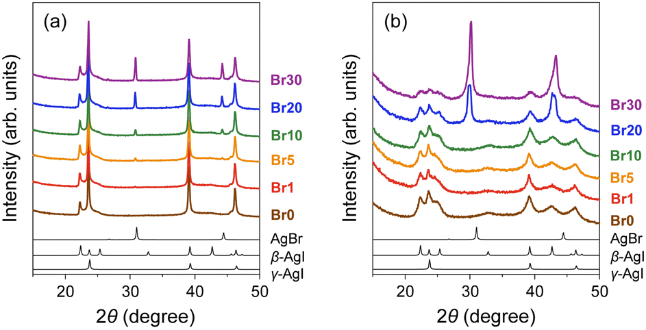 | ||
| Fig. 1 PXRD patterns of AgI–AgBr/MPA composites with various AgI:AgBr molar ratios (a) before and (b) after heat treatment at 600 °C for 20 h (brown: Br0, red: Br1, orange: Br5, green: Br10, blue: Br20, purple: Br30). Black lines show the simulated patterns of AgBr, β-AgI, and γ-AgI (from the top). | ||
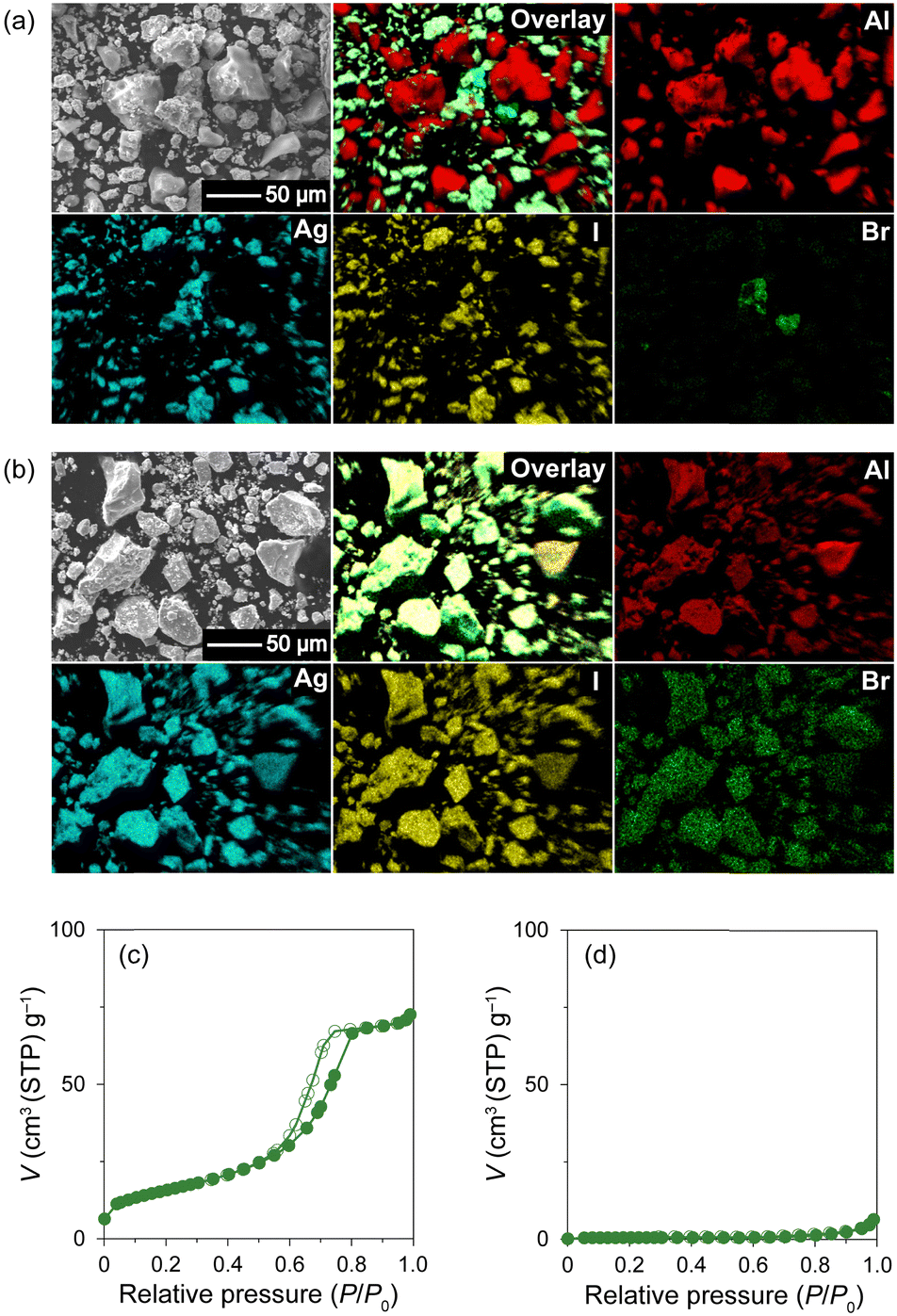 | ||
| Fig. 2 SEM images and EDS mappings (overlay, Al, Ag, I, and Br) of Br10 (a) before and (b) after heat treatment. N2 gas adsorption (closed circles) and desorption (open circles) isotherms of Br10 (c) before and (d) after heat treatment. | ||
The PXRD peaks of the composites with AgBr ≤ 10 mol% (i.e., Br0–Br10) were assigned only to β- or γ-AgI phases, whereas the PXRD patterns of the composites with AgBr > 10 mol% (i.e., Br20 and Br30) exhibited additional peaks that were assigned to the face-centred cubic (fcc) AgBr phase (Fig. 1(b)). Therefore, the composites with AgBr ≤ 10 mol% form a homogeneous solid solution with β/γ-AgI-type structures in which AgBr was dissolved in the AgI lattice (hereafter β/γ-AgIss), whereas those with AgBr > 10 mol% underwent a phase separation into the aforementioned β/γ-AgIss and another solid-solution phase in which AgI was dissolved in the AgBr lattice (hereafter AgBrss). Furthermore, the formation of the solid solution of AgI in the AgBr lattice is evident from the shift of the (200) reflection of AgBrss to the lower angle side than that in parent bulk AgBr (e.g., 29.9° for Br20vs. 30.9° for parent bulk AgBr) as a reflection of the partial substitution of Br atoms with larger I atoms in the AgBr lattice (ionic radius: 1.96 Å for Br−, 2.19 Å for I−74,75). On the other hand, the PXRD peaks of β/γ-AgIss were barely shifted by the heat treatment, which can be attributed to the fact that the amount of AgBr dissolved in AgI is less than that of AgI dissolved in AgBr as observed in bulk AgI–AgBr mixed crystals.52,55,73,76,77
To investigate the effect of AgBr-doping on the thermal behaviour, the DSC profiles of the AgI–AgBr/MPA composites were measured during the heating and cooling processes. Focusing on the cooling process, two exothermic peaks were observed for the composites with AgBr ≤ 10 mol% (i.e., Br0–Br10; Fig. 3(a)–(d)). Given that the composites remain a single β/γ-AgIss phase in this AgBr content region at room temperature (Fig. 1(b)), both DSC peaks can be assigned to the structural phase transition from the α- to β/γ-phases of AgIss. In our previous paper,47 we identified that the high- and low-temperature DSC peaks observed for the parent AgI/MPA composite (i.e., Br0) are associated with the bulk-like AgI occupying the core and AgI near the surface of the pores, respectively. Therefore, it is possible that the same assignment holds for AgI–AgBr/MPA composites. For the composites with AgBr > 10 mol% (i.e., Br20 and Br30), only one exothermic peak, possibly corresponding to the low-temperature side, was observed, as shown in Fig. 3(e) and (f). Because the heating scan of the DSC profile of Br20 exhibited two distinct endothermic peaks assignable to the β/γ-AgIss-to-α-AgIss and AgBrss-to-α-AgIss (α-AgIss: solid-solution phase with α-AgI structure) at ca. 110 and 170 °C, respectively,70 it is likely that the corresponding exothermic DSC peaks merge into the broad peak in the cooling process. This is reinforced by the very broad temperature range of the phase transitions observed in the temperature-dependent PXRD measurements (see below). Furthermore, the transition enthalpy comparable to those of the composites with AgBr ≤ 20 mol% (Fig. 4(a)) supports the assignment. On the other hand, the transition enthalpy of Br30 is significantly lower than the others, which may be associated with the significant increase in the AgBrss-to-α-AgIss transition temperature as observed in bulk AgI–AgBr mixed crystals (ca. 200 °C for AgBr = 30 mol%).52,55,73,76,77 The incomplete transition to α-AgIss in the measured temperature range was verified by the temperature-dependent PXRD measurements (see below).
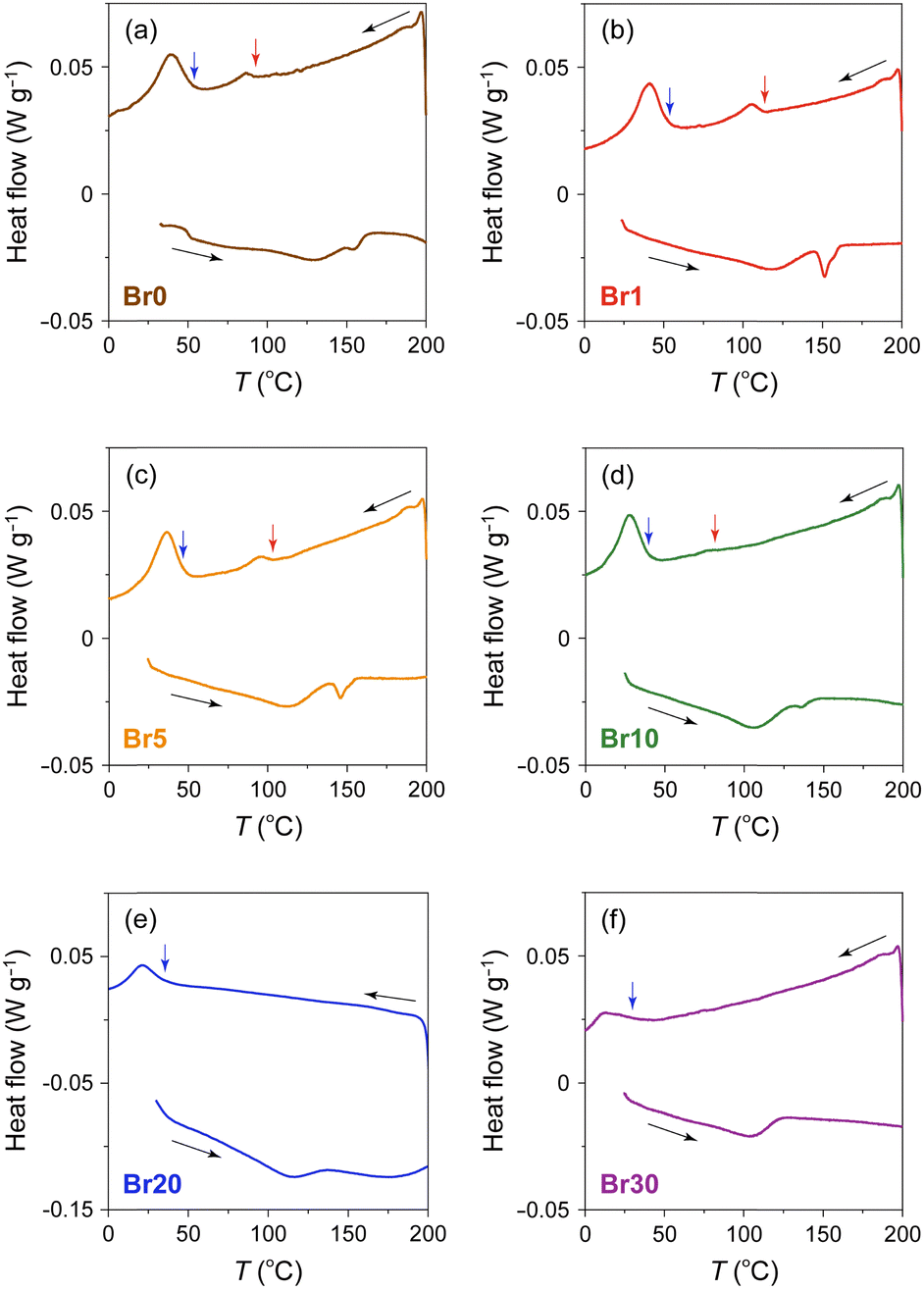 | ||
| Fig. 3 DSC profiles of AgI–AgBr/MPA composites with various AgI:AgBr molar ratios ((a) Br0, (b) Br1, (c) Br5, (d) Br10, (e) Br20, and (f) Br30). The red and blue arrows indicate the onset temperatures of the transition on the high- and low-temperature sides, respectively, in the cooling process. | ||
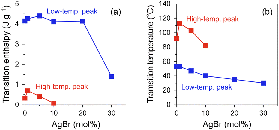 | ||
| Fig. 4 AgBr-doping ratio dependence of (a) transition enthalpy and (b) transition temperatures determined by DSC profile in the cooling process (red: high-temperature peak, blue: low-temperature peak). | ||
As shown in Fig. 4(b), the onset temperatures of the peaks decreased with increasing AgBr-doping ratio. The rapid decrease in the transition temperatures of the composites with AgBr ≤ 10 mol% can be primarily attributed to the lattice distortion induced by AgBr-doping, which causes the increase in the Frenkel defect concentration to stabilise the high-temperature phase. Furthermore, the phase separation observed in the composites with AgBr > 10 mol% may suppress the α-AgIss-to-β/γ-AgIss transition in the cooling process.
Variable-temperature PXRD measurements of the AgI–AgBr/MPA composites were performed to understand their phase transition behaviour from a structural perspective. Fig. 5(a) shows the PXRD patterns of Br10 during heating and cooling processes. The as-prepared composite demonstrated the PXRD peaks assignable to β/γ-AgIss at 30 °C with a trace of AgBrss (2θ = 30.3°), which disappeared after cyclic heating and cooling treatments implying the metastable nature of the phase in this composite. On heating, the β/γ-AgIss peaks began to disappear at ca. 100 °C with the concurrent appearance of the α-AgIss peak, and eventually became invisible above ca. 150 °C. The phase transition was more explicit when the ratio of each phase determined by Rietveld analysis is plotted as a function of temperature (Fig. 5(b)). Refinements were performed under the assumption that only I atoms occupy the halogen sites in AgIss, whereas only Br atoms occupy the sites in AgBrss. In the subsequent cooling process, the α-AgIss phase was maintained down to ca. 60 °C, below which it underwent a reversible transformation to the β/γ-AgIss phase (Fig. 5(c)). It is readily apparent that the structural transition occurs at which an intense peak was observed in the DSC profile (Fig. 3(d)), supporting the above identification of the phase transition. In addition, we measured the temperature dependence of the PXRD patterns of Br20 (Fig. 5(d)) and Br30 (Fig. 5(g)), which underwent a phase separation into β/γ-AgIss and AgBrss at room temperature. The molar ratios of the AgI/AgBr phases were estimated to be 33:67 for Br20 and 14:86 for Br30 based on the Rietveld refinement, indicating that a significant level of I atoms was incorporated in AgBrss as mentioned above. For Br20, the gradual disappearance of both phases entailed the appearance of the α-AgIss phase in the temperature range of 110–140 °C for β/γ-AgIss and 110–180 °C for AgBrss (Fig. 5(e)), which are possibly associated with the broad endothermic DSC peaks at approximately 110 and 170 °C, respectively, in the heating process. In the cooling process, the α-AgIss phase was reversibly transformed to the β/γ-AgIss and AgBrss phases (Fig. 5(f)), although there was only one exothermic DSC peak at ca. 40 °C. Considering that gradual phase transition processes were observed in the PXRD measurements, the DSC peaks assigned to the two transitions may have merged into a broad peak as mentioned above. The temperature-dependent PXRD data of Br30 bear a few similarities to Br20, along with several striking differences. As shown in Fig. 5(h), the β/γ-AgIss phase in Br30 disappeared at ca. 120 °C in the heating process, which is associated with the broad endothermic DSC peak at approximately 110 °C. The corresponding α-AgIss-to-β/γ-AgIss transition, which is responsible for the DSC peak with the onset temperature at 30 °C, was observed at approximately 40 °C in the cooling process (Fig. 5(i)). It is noteworthy that the AgBrss phase in Br30 remained stable even at 195 °C, which must cause the observed low transition enthalpy (Fig. 4(a)). The phase diagram of the AgI–AgBr/MPA composites, in which the phase boundaries were defined when the molar ratio of β/γ-AgIss or AgBrss phase reaches 50% relative to that at 30 °C, resembles that of bulk AgI–AgBr mixed crystals55 with a slight shift towards a lower temperature (Fig. S5, ESI†).
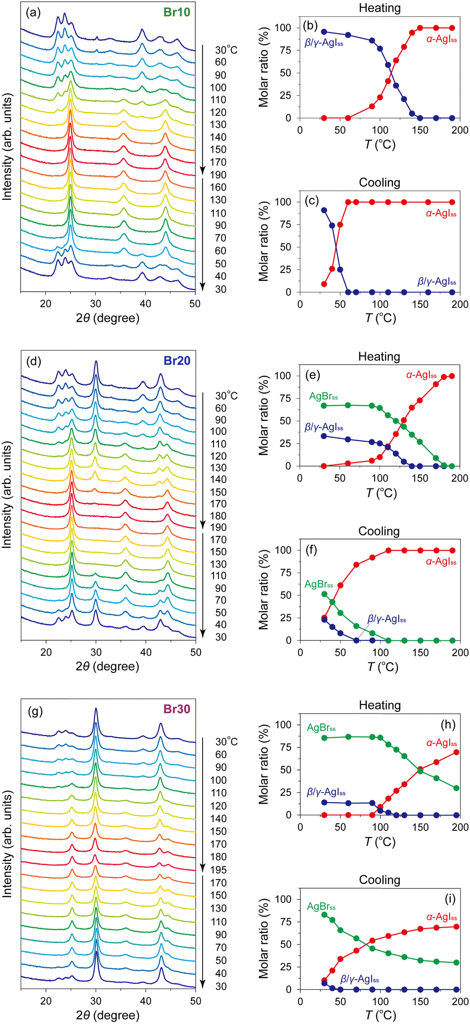 | ||
| Fig. 5 Variable-temperature PXRD patterns of (a) Br10, (d) Br20, and (g) Br30 in the heating and cooling processes. Temperature dependences of the molar ratios of α- (red) and β/γ- (blue) AgIss phases of Br10 in the heating (b) and cooling (c) processes and the molar ratios of α-AgIss (red), β/γ-AgIss (blue), and AgBrss (green) phases of Br20 and Br30 in the heating ((e) and (h)) and cooling ((f) and (i)) processes. The ratios were determined by the Rietveld analyses. | ||
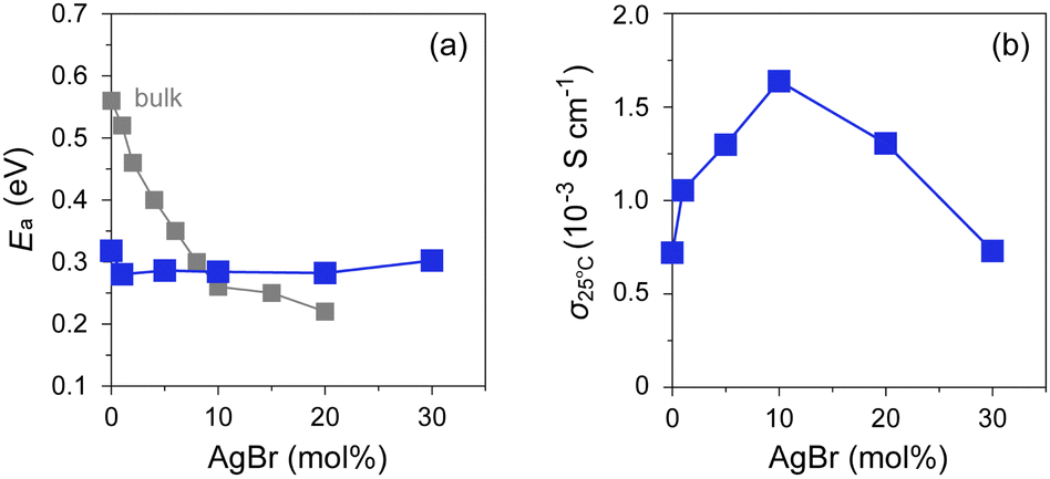
The ionic conductivity (σ) of the AgI–AgBr/MPA composites with various AgI:AgBr molar ratios was measured using AC impedance spectroscopy (Fig. 6 and Fig. S6, ESI†). The room-temperature value (σ25°C) lies in the order of 10−4–10−3 S cm−1, which is significantly higher than that of bulk AgI (ca. 1.5 × 10⁻⁷ S cm−1).16 As shown in Fig. 6, the composites with AgBr ≤ 10 mol% exhibited an Arrhenius-type ionic conduction up to approximately 140 °C, whereas those with AgBr > 10 mol% showed a moderate continuous increase in σ with increasing temperature up to the highest measured temperature (200 °C) without any significant slope change. Considering the fact that the composites with AgBr > 10 mol% formed a phase separation between β/γ-AgIss and AgBrss at room temperature, it is possible that the phase separation suppresses the discontinuous change in σ as observed for bulk AgI, which must be reflected in a very gradual increase in the ratio of α-AgIss phase on heating (Fig. 5(e) and (h)). The activation energy (Ea) values estimated by fitting the data up to 130 °C to the Arrhenius equation, σT = Aexp(−Ea/kBT), where A is the pre-exponential factor and kB is the Boltzmann constant, are shown in Fig. 7(a). The Ea values of the bulk AgI–AgBr mixed crystals reported by Shahi and Wagner are also shown for comparison.49–51,78 The Ea value of AgX is generally expressed as Ea = Hf/2 + hm, where the migration energy of Frenkel defects (hm) is smaller than the formation enthalpy of Frenkel defects (Hf).50,79 Thus the lower Ea value of Br0 (0.32 eV) than that of bulk AgI (0.56 eV) can be attributed to the decreased Hf owing to the formation of AgI nanoparticles in the mesopores of MPA and the decreased hm owing to the space charge layer formed at the interface with MPA. The Ea values of the AgI–AgBr/MPA composites remained relatively unchanged with the AgBr content, whereas the values of the bulk AgI–AgBr mixed crystals steadily decreased with increasing AgBr content (Fig. 7(a)). Apparently, the decrease in Ea in the bulk AgI–AgBr mixed crystals arose from the decrease in Hf with increasing AgBr content due to the lattice distortion induced by the partial substitution of I with Br in the AgI lattice. At present, the factor that keeps the Ea values nearly constant in the AgI–AgBr/MPA composites is unclear. However, the tendency seems to be associated with the fact that the 2-fold increase in σ25°C with 10 mol% AgBr doping in the AgI–AgBr/MPA composite (see below) is significantly low compared with the increase in three orders of magnitude in the bulk AgI–AgBr mixed crystals. The σ value at 200 °C was the highest for the composite with AgBr = 10 mol% (i.e., Br10; 5.7 × 10⁻² S cm−1), above which the value exhibited a gradual decrease with increasing AgBr content (3.4 × 10⁻² S cm−1 for Br30) (Fig. S7, ESI†), primarily due to the incomplete transition to the highly ion-conducting α-phase.
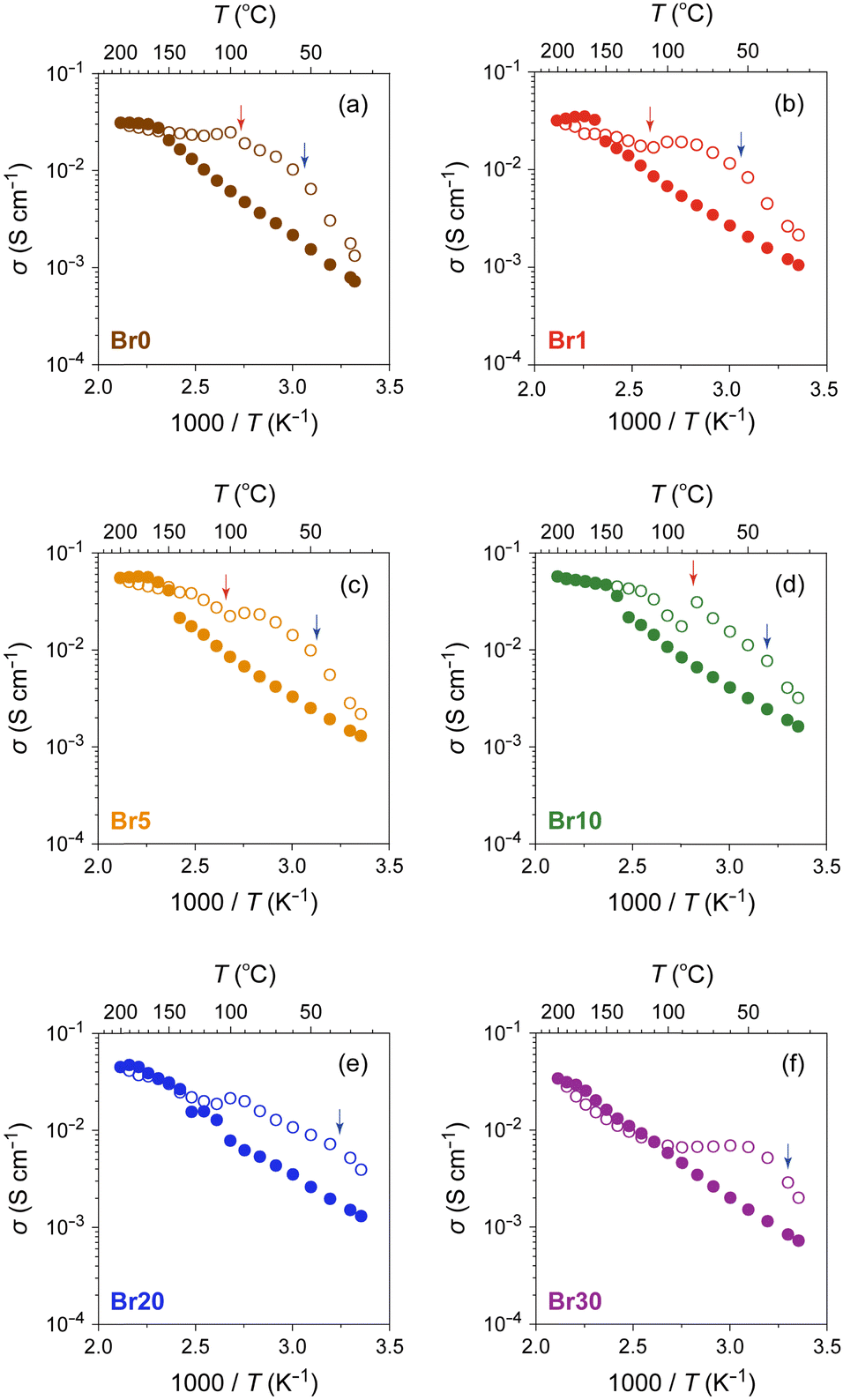 | ||
| Fig. 6 Temperature dependence of σ for AgI–AgBr/MPA composites with various AgI:AgBr molar ratios ((a) Br0, (b) Br1, (c) Br5, (d) Br10, (e) Br20, and (f) Br30) in heating (closed circles) and cooling (open circles) processes. The red and blue arrows indicate the onset temperatures of the transition on the high- and low-temperature sides, respectively, in the DSC cooling process (Fig. 3). | ||
 | ||
| Fig. 7 Plots of (a) Ea and (b) σ25°C against AgBr-doping ratio for AgI–AgBr/MPA composites represented by closed blue squares. Closed grey squares represent the values of bulk AgI–AgBr mixed crystals.49–51,78 | ||
The ion-conducting behaviour in the subsequent cooling process was considerably different from that in the heating process for each composite (Fig. 6). For the composites with AgBr ≤ 10 mol%, the temperature at which the valley-like σ behaviour was observed (ca. 100 °C) corresponds approximately to the onset temperature of the exothermic DSC peaks on the high-temperature side (red arrows). Considering the fact that the structural transformation from α-AgIss to β/γ-AgIss with an expanded lattice (e.g., 64.0 Å3 per formula unit for α-AgIss at 110 °C vs. 67.8 Å3 per formula unit for β-AgIss at 30 °C in Br10) occurs at the core of the mesopores below the temperature, the flattening or upturn of σ observed in the temperature range may be attributed to the connection of the Ag+-ion conducting percolation pathways26,80–82 formed by the α-AgIss region owing to the expanded lattice on cooling.31 Similarly, the valley-like behaviour of σ was observed at approximately 100 °C for the composites with AgBr > 10 mol%, although there is no DSC peak in the temperature range. However, given that the variable-temperature PXRD measurements of Br20 and Br30 exhibited a nearly constant or increasing unit cell volume of the α-AgIss phase on cooling (Fig. S8, ESI†), the expanded lattice may be the primary cause of the non-Arrhenius-type conduction observed in the cooling process. We confirmed that the room-temperature PXRD pattern remained unchanged after the cyclic heating and cooling processes (Fig. S9, ESI†).
As shown in Fig. 7(b), the AgBr-doping ratio dependence of σ25°C showed a volcano-type correlation with a maximum at AgBr = 10 mol% (i.e., Br10). It is evident that the σ value (1.6 × 10⁻³ S cm−1) is more than twice as high as that of the highest conducting AgI/MPA (i.e., Br0; 7.2 × 10⁻⁴ S cm−1) reported in our previous paper.47 An increase in σ25°C in the low AgBr-doping range is possibly related to the increase in Ag+ migration caused by an increased concentration of Frenkel defects due to the lattice distortion. A decrease in σ25°C in the high AgBr-doping range is caused by phase separation as evidenced by the PXRD measurements, which disturbs the Ag+-ion diffusion at the phase boundary in the composites (Fig. S10, ESI†).
Conclusions
In this study, our research interest is centred on the variable-temperature structural, calorimetric, and Ag+ ion-conducting properties of AgI/AgBr-loaded mesoporous alumina with various AgBr doping ratios. We found that the ionic conductivity of the AgI–AgBr/MPA composite with AgBr = 10 mol% exceeded 10−3 S cm−1 at room temperature; the value, 1.6 × 10⁻³ S cm−1, is more than twice as high as that of the highest ion-conducting AgI/MPA found in our previous study (7.2 × 10⁻⁴ S cm−1).47 An increase in the AgBr content facilitates the formation of Frenkel pairs owing to lattice distortion, and the formed interstitial Ag+ ions lead to enhanced ionic conductivity. A further increase in the AgBr content causes the decrease in ionic conductivity due to the occurrence of phase separation. Solid-solution composite systems have the great advantage of using various combinations of homovalent anions and various selections of porous materials, which would allow for the rational design of highly ion-conducting composites.Conflicts of interest
There are no conflicts to declare.Acknowledgements
This work was supported by the ACCEL program (JPMJAC1501) of the Japan Science and Technology Agency (JST) and JSPS KAKENHI Grant Numbers JP20H02708 and JP20H05623. Variable-temperature PXRD measurements were conducted at the University of Tokyo, supported by “Advanced Research Infrastructure for Materials and Nanotechnology in Japan (ARIM)” of the Ministry of Education, Culture, Sports, Science and Technology (MEXT), Grant Number JPMXP1223UT0224.Notes and references
- P. Knauth and J. Schoonman, Nanostructured Materials: Selected Synthesis Methods, Properties and Applications, Kluwer Academic Publishers, Dordrecht, 2002 Search PubMed.
- T. Minami, M. Tatsumisago, M. Wakihara, C. Iwakura, S. Kohjiya and I. Tanaka, Solid State Ionics for Batteries, Springer, Tokyo, 2005 Search PubMed.
- J. Schoonman, Solid State Ionics, 2000, 135, 5–19 CrossRef CAS.
- P. Knauth and H. L. Tuller, J. Am. Ceram. Soc., 2002, 85, 1654–1680 CrossRef CAS.
- K. Funke, Sci. Technol. Adv. Mater., 2013, 14, 043502 CrossRef CAS PubMed.
- Z. Zou, Y. Li, Z. Lu, D. Wang, Y. Cui, B. Guo, Y. Li, X. Liang, J. Feng, H. Li, C. W. Nan, M. Armand, L. Chen, K. Xu and S. Shi, Chem. Rev., 2020, 120, 4169–4221 CrossRef CAS PubMed.
- F. Wu, L. Liu, S. Wang, J. Xu, P. Lu, W. Yan, J. Peng, D. Wu and H. Li, Prog. Mater. Sci., 2022, 126, 100921 CrossRef CAS.
- B. B. Owens, J. Power Sources, 2000, 90, 2–8 CrossRef CAS.
- S. Ohno, A. Banik, G. F. Dewald, M. A. Kraft, T. Krauskopf, N. Minafra, P. Till, M. Weiss and W. G. Zeier, Prog. Energy, 2020, 2, 022001 CrossRef.
- R. G. Pearson, J. Am. Chem. Soc., 1963, 85, 3533–3539 CrossRef CAS.
- C. Tubandt and E. Lorenz, Z. Phys. Chem., 1914, 87U, 513–542 CrossRef.
- G. Cochrane and N. H. Fletcher, J. Phys. Chem. Solids, 1971, 32, 2557–2567 CrossRef CAS.
- T. Takahashi, J. Appl. Electrochem., 1973, 3, 79–90 CrossRef CAS.
- K. Funke, Prog. Solid State Chem., 1976, 11, 345–402 CrossRef.
- S. Hull, Rep. Prog. Phys., 2004, 67, 1233–1314 CrossRef CAS.
- R. Makiura, T. Yonemura, T. Yamada, M. Yamauchi, R. Ikeda, H. Kitagawa, K. Kato and M. Takata, Nat. Mater., 2009, 8, 476–480 CrossRef CAS PubMed.
- S. Yamasaki, T. Yamada, H. Kobayashi and H. Kitagawa, Chem. – Asian J., 2013, 8, 73–75 CrossRef CAS PubMed.
- T. Yamamoto, M. Maesato, N. Hirao, S. I. Kawaguchi, S. Kawaguchi, Y. Ohishi, Y. Kubota, H. Kobayashi and H. Kitagawa, J. Am. Chem. Soc., 2017, 139, 1392–1395 CrossRef CAS PubMed.
- T. Yamamoto, H. Kobayashi, L. S. R. Kumara, O. Sakata, K. Nitta, T. Uruga and H. Kitagawa, Nano Lett., 2017, 17, 5273–5276 CrossRef CAS PubMed.
- T. Ida and K. Kimura, Solid State Ionics, 1998, 107, 313–318 CrossRef CAS.
- M. Nagai and T. Nishino, J. Electrochem. Soc., 1991, 138, L49–L51 CrossRef CAS.
- M. Nagai and T. Nishino, Solid State Ionics, 1992, 53–56, 63–67 CrossRef.
- M. Nagai and T. Nishino, J. Am. Ceram. Soc., 1993, 76, 1057–1060 CrossRef CAS.
- M. Nagai and T. Nishino, Solid State Ionics, 1999, 117, 317–321 CrossRef CAS.
- K. Tadagana, K. Imai, M. Tatsumisago and T. Minami, J. Electrochem. Soc., 2000, 147, 4061–4064 CrossRef.
- H. Yamada, A. J. Bhattacharyya and J. Maier, Adv. Funct. Mater., 2006, 16, 525–530 CrossRef CAS.
- H. Yamada, I. Saruwatari, N. Kuwata and J. Kawamura, J. Phys. Chem. C, 2014, 118, 23845–23852 CrossRef CAS.
- C. Liang, K. Terabe, T. Hasegawa and M. Aono, J. Appl. Phys., 2007, 102, 124308 CrossRef.
- C. Liang, K. Terabe, T. Tsuruoka, M. Osada, T. Hasegawa and M. Aono, Adv. Funct. Mater., 2007, 17, 1466–1472 CrossRef CAS.
- H. Zhang, T. Tsuchiya, C. Liang and K. Terabe, Nano Lett., 2015, 15, 5161–5167 CrossRef CAS PubMed.
- L. Liu, S. Lee, J. Li, M. Alexe, G. Rao, W. Zhou, J. Lee, W. Lee and U. Gösele, Nanotechnology, 2008, 19, 495706 CrossRef PubMed.
- W. Lee, H. Yoo and J. Lee, Chem. Commun., 2001, 18318–18322 Search PubMed.
- K. Tadagana, K. Imai, M. Tatsumisago and T. Minami, J. Electrochem. Soc., 2002, 149, A773–A777 CrossRef.
- S. Albert, N. Frolet, P. Yot, A. Pradel and M. Ribes, Solid State Ionics, 2006, 177, 3009–3013 CrossRef CAS.
- S. V. Baryshnikov, C. Tien, E. V. Charnaya, M. K. Lee, D. Michel, W. Böhlmann and N. P. Andriyanova, Phys. Solid State, 2008, 50, 1342–1346 CrossRef CAS.
- S. V. Baryshnikov, C. Tien, E. V. Charnaya, M. K. Lee, D. Michel, W. Böhlmann and N. P. Andriyanova, J. Phys.: Condens. Matter, 2008, 20, 025214 CrossRef.
- A. Pradel, P. Yot, S. Albert, N. Frolet and M. Ribes, in Nanostructured Materials for Advanced Technological Applications, ed. J. P. Reithmaier, P. Petkov, W. Kulisch and C. Popov, Springer, Dordrecht, 2009, pp. 233–243 Search PubMed.
- P. G. Yot, S. Albert, N. Frolet, M. Ribes and A. Pradel, J. Phys. Chem. C, 2010, 114, 18318–18322 CrossRef CAS.
- A. V. Il’inskii, R. A. Aliev, D. A. Kurdyukov, N. V. Sharenkova, E. B. Shadrin and V. G. Golubev, Phys. Status Solidi A, 2006, 203, 2073–2077 CrossRef.
- M. Reháková, M. Casciola, I. G. K. Andersen and Z. Bastl, J. Inclusion Phenom. Mol. Recognit. Chem., 1996, 25, 303–312 CrossRef.
- J. Maier, Prog. Solid State Chem., 1995, 23, 171–263 CrossRef CAS.
- K. L. Kliewer and J. S. Koehler, Phys. Rev., 1965, 140, A1226–A1240 CrossRef.
- K. L. Kliewer, Phys. Rev., 1965, 140, A1241–A1246 CrossRef.
- K. L. Kliewer, J. Phys. Chem. Solids, 1966, 27, 705–717 CrossRef CAS.
- T. Jow and J. B. Wagner Jr, J. Electrochem. Soc., 1979, 126, 1963–1972 CrossRef CAS.
- R. C. Agrawal and R. K. Gupta, J. Mater. Sci., 1999, 34, 1131–1162 CrossRef CAS.
- Y. Fukui, Y. Yoshida, H. Kitagawa and Y. Jikihara, Phys. Chem. Chem. Phys., 2023, 25, 25594–25602 RSC.
- K. Shahi and J. B. Wagner Jr., Appl. Phys. Lett., 1980, 37, 757–759 CrossRef CAS.
- K. Shahi and J. B. Wagner Jr., Solid State Ionics, 1981, 3–4, 295–299 CrossRef CAS.
- K. Shahi and J. B. Wagner Jr., Phys. Rev. B: Condens. Matter Mater. Phys., 1981, 23, 6417–6421 CrossRef CAS.
- K. Shahi and J. B. Wagner Jr., J. Phys. Chem. Solids, 1982, 43, 713–722 CrossRef CAS.
- K. Shahi and J. B. Wagner Jr., Solid State Ionics, 1984, 12, 511–516 CrossRef CAS.
- A. Khandkar, V. B. Tare, A. Navrotsky and J. B. Wagner Jr., J. Electrochem. Soc., 1984, 131, 2683–2687 CrossRef CAS.
- L. S. Cain and L. M. Slifkin, J. Phys. Chem. Solids, 1980, 41, 173–178 CrossRef CAS.
- H. Takahashi, S. Tamaki and S. Harada, Solid State Ionics, 1984, 14, 107–112 CrossRef CAS.
- H. Takahashi and S. Tamaki, Solid State Ionics, 1985, 15, 43–49 CrossRef CAS.
- H. Takahashi, S. Tamaki and Y. Waseda, Solid State Ionics, 1988, 31, 55–72 CrossRef CAS.
- M. Inui, K. Maruyama, Y. Shirakawa, S. Takeda and S. Tamaki, J. Non-Cryst. Solids, 1996, 205–207, 155–158 CrossRef CAS.
- M. Kusakabe, M. Arai, Y. Ito and S. Tamaki, Solid State Ionics, 1999, 121, 295–299 CrossRef CAS.
- A. Yoshiasa, K. Koto, S. Emura and F. Kanamaru, J. Phys. Colloq., 1986, 47, 803–807 CrossRef.
- A. Yoshiasa, F. Kanamaru, S. Emura and K. Koto, Solid State Ionics, 1988, 27, 267–274 CrossRef CAS.
- A. Yoshiasa, F. Kanamaru and K. Koto, Solid State Ionics, 1988, 27, 275–283 CrossRef CAS.
- M. Palanisamy, K. Thangaraj, R. Gobinathan and P. Ramasamy, J. Mater. Sci., 1987, 22, 670–674 CrossRef CAS.
- U. Lauer and J. Maier, Solid State Ionics, 1992, 51, 209–213 CrossRef CAS.
- R. K. Gupta and R. C. Agrawal, Solid State Ionics, 1994, 72, 314–317 CrossRef CAS.
- R. C. Agrawal, R. Kumar, R. K. Gupta and M. Saleem, J. Non-Cryst. Solids, 1995, 181, 110–115 CrossRef CAS.
- R. C. Agrawal, M. L. Verma, R. K. Gupta and S. Thaker, Solid State Ionics, 2000, 136–137, 473–478 CrossRef CAS.
- R. K. Nagarch, R. Kumar and R. C. Agrawal, J. Non-Cryst. Solids, 2006, 352, 450–457 CrossRef CAS.
- R. K. Nagarch, R. Kumar and R. C. Agrawal, J. Non-Cryst. Solids, 2006, 352, 458–462 CrossRef CAS.
- J. F. Jurado, J. A. Trujillo, B.-E. Mellander and R. A. Vargas, Solid State Ionics, 2003, 156, 103–112 CrossRef CAS.
- S. Matsunaga, Solid State Ionics, 2005, 176, 1929–1940 CrossRef CAS.
- S. Matsunaga, J. Non-Cryst. Solids, 2007, 353, 3459–3462 CrossRef CAS.
- A. Yuzhakova, D. Salimgareev, A. Turabi, A. Korsakov and L. Zhukova, Opt. Laser Technol., 2021, 139, 106995 CrossRef CAS.
- R. D. Shannon and C. T. Prewitt, Acta Crystallogr., Sect. B: Struct. Crystallogr. Cryst. Chem., 1969, 25, 925–946 CrossRef CAS.
- R. D. Shannon, Acta Crystallogr., Sect. A: Cryst. Phys., Diffr., Theor. Gen. Crystallogr., 1976, 32, 751–767 CrossRef.
- O. Stasiw and J. Teltow, Z. Anorg. Allg. Chem., 1949, 259, 143–153 CrossRef CAS.
- M. K. Reser, Phase Diagrams for Ceramists, The American Ceramic Society, 1964 Search PubMed.
- Authors in ref. 49–51 estimated the Ea values using an equation, σ = Aexp(−Ea/kBT), instead of σT = Aexp(−Ea/kBT).
- P. Müller, Phys. Status Solidi, 1965, 12, 775–794 CrossRef.
- A. Bunde, Solid State Ionics, 1995, 75, 147–155 CrossRef CAS.
- A. Bunde and W. Dieterich, J. Electroceram., 2000, 5, 81–92 CrossRef CAS.
- N. F. Uvarov, P. Vaněk, M. Savinov, V. Železný, V. Studnička and J. Petzelt, Solid State Ionics, 2000, 127, 253–267 CrossRef CAS.
Footnote |
| † Electronic supplementary information (ESI) available: Fig. S1–S13. See DOI: https://doi.org/10.1039/d4cp00744a |
| This journal is © the Owner Societies 2024 |