Interfacial engineering of a polymer–MOF composite by in situ vitrification†
Rijia
Lin
 a,
Jingwei
Hou
 *a,
Mengran
Li
 a,
Zhanke
Wang
a,
Lei
Ge
a,
Zhanke
Wang
a,
Lei
Ge
 b,
Shichun
Li
 c,
Simon
Smart
ad,
Zhonghua
Zhu
 a,
Thomas D.
Bennett
 e and
Vicki
Chen
a
aSchool of Chemical Engineering, The University of Queensland, Brisbane 4072, Australia. E-mail: jingwei.hou@uq.edu.au
bCentre for Future Materials, University of Southern Queensland, Queensland 4300, Australia
cInstitute of Chemical Materials, China Academy of Engineering Physics, Mianyang 621900, P. R. China
dDow Centre for Sustainable Engineering Innovation, The University of Queensland, QLD 4072, Australia
eDepartment of Materials Science and Metallurgy, University of Cambridge, Cambridge, CB3 0FS, UK
First published on 9th March 2020
Abstract
Non-stoichoimetric crystalline ZIF-62 was used as the filler for a 6FDA-DAM polyimide-based composite membrane. In situ melting and vitrification of ZIF-62 was then performed, to yield the ZIF-62 glass phase (agZIF-62), within the polymer matrix. Focus ion beam scanning electron microscopy (FIB-SEM), thermal characterisation and membrane separation tests demonstrate the filling of voids at the MOF/polymer interface from the liquid phase of ZIF-62.
The chemical and structural versatility of metal–organic frameworks (MOFs) has led to a host of different applications including toxic gas capture, water harvesting, molecular sieving, drug delivery and catalysis.1–3 Interest in MOFs is gradually shifting from new material development, which currently stands at over 70
![[thin space (1/6-em)]](https://www.rsc.org/images/entities/char_2009.gif) 000 structures,4 to material assembly towards macroscopic structures. However, most MOF materials are synthesised as discrete polycrystalline powders, which render them difficult to process. Therefore, the knowledge gap between material synthesis and their practical application is still significant. Innovative techniques to circumvent the relatively ‘soft’ mechanical properties of MOFs including sol–gel processing have been proposed, but are typically limited to case-by-case bases.4,5
000 structures,4 to material assembly towards macroscopic structures. However, most MOF materials are synthesised as discrete polycrystalline powders, which render them difficult to process. Therefore, the knowledge gap between material synthesis and their practical application is still significant. Innovative techniques to circumvent the relatively ‘soft’ mechanical properties of MOFs including sol–gel processing have been proposed, but are typically limited to case-by-case bases.4,5
A more straightforward and scalable approach is the use of MOF–fillers in polymeric binders to impart mechanical strength and processability to MOF-based materials. A wealth of reports exist on the technique, with potential applications of the resultant MOF–polymer composites in adsorption columns, sensors, batteries and, particularly, mixed matrix membranes.6 Optimal performance of such materials however relies upon obtaining a solution to the typically poor compatibility between MOF and polymer phases.7 For example, poor interfacial adhesion can generate nonselective defects, which are detrimental to the separation efficiency of membranes.8 Several techniques have been implemented to mitigate this issue including pre-functionalization of the MOF surface,9in situ nucleation of MOF fillers within polymer matrices,10in situ polymerisation with the presence of MOF fillers,11 morphological modification of MOF fillers,12–14 and the use of interface agents.15,16 A one step post-treatment involving thermal treatment would be particularly appealing, given the relative simplicity and industrial applicability. Progress has also been made here, though is limited to a few reports on the in situ formation of coordination bonds between polymeric substrates and MOF fillers via annealing.17
Recently, the overwhelming dominance of the crystalline state in the MOF field has begun to be challenged through the synthesis and application of non-crystalline, or amorphous MOFs in proton conduction, electrochemical applications, membrane separation and encapsulation.17–19 The liquid MOF phase, alongside the glasses formed upon quenching are of particular interest.20 The zeolitic imidazolate framework (ZIF) family have been extensively investigated, with melting demonstrated to proceed via breaking of metal–ligand coordinative bonds, without change in the stoichiometry. Subsequent quenching allows the disordered node-linker arrangement to be kinetically preserved by avoiding re-crystallisation. The resultant glass is, like the crystalline phase, composed of tetrahedral MN4 nodes, although it has lost the long-range order of the crystalline materials. Liquid and glass MOFs enable numerous possibility in the fabrication of new MOF materials, such as MOF glass blend, flux melted MOF, MOF crystal-glass composite and functionalized MOF glasses.21 Recent work on the reactive nature of several high temperature liquid ZIFs22 together with the innate ability of glass to yield bulk properties not available in crystalline materials, e.g. the absence of grain boundaries and high processability.23 The ZIF glass enables its shaping towards macroscopic structures at the molten liquid state. This drives us to use the liquid ZIF state to regulate the surface and interface properties of MOF-polymer composites (Fig. 1).
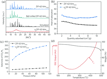
Non-stoichoimetric ZIF-62 [Zn(Im)1.95(bIm)0.05],24 referred to as ZIF-62-bIm0.05 hereafter, was selected due to the low melting temperature (Tm = 357.8 °C in Ar, Fig. S1, ESI†), and relatively high porosity in the glass state. The molar ratio of bIm/Im linker in ZIF-62 crystal and ZIF-62 glass is confirmed by liquid NMR (Fig. S2–S4, ESI†). Bulk octahedral crystals of ZIF-62-bIm0.05 (ca. 100 μm) were first obtained from a hydrothermal synthesis in N,N-dimethylformamide (DMF) at 130 °C for 7 d, then the size of ZIF-62-bIm0.05 was reduced by using a ball mill 1 h at a rotational speed of 800 rpm (ca. 1 μm, Fig. S5, ESI†). Extensive grinding was avoided to mitigate mechanical induced amorphisation (Fig. 2). The vitrification of this sample was confirmed according to the XRD results (Fig. 2a). After vitrification, the melt-quenched glass (termed as agZIF-62-bIm0.05 in line with our previous publications) shows a diffuse scattering centred at ca. 16°, indicating the collapse of the crystalline structure and the formation of the agZIF-62-bIm0.05 after vitrification. Scanning electron microscopic images confirmed the formation of coherent morphologies upon melt quenching (Fig. S5, ESI†).
The microporous structure of ZIF-62-bIm0.05 before, and after melt-quenching was probed using CO2 and N2 adsorption isotherms (Fig. S6, ESI†). The surface area and pore size distribution of ZIF-62-bIm0.05 and agZIF-62-bIm0.05 were fitted with a nonlocal density functional theory model (NLDFT, CO2, 273 K, carbon with slit-pore geometry),24,25 using experimental CO2 adsorption isotherms collected at 273 K. The as-synthesized ZIF-62-bIm0.05 crystal has a surface area (NLDFT) around 476 m2 g−1. agZIF-62-bIm0.05 still retains significant microporosity, with the surface area (NLDFT) being ca. 173 m2 g−1. This reduced surface area is mainly attributed to the cavities loss at 3.2–5.3 Å due to the partial collapse of the framework, whilst the larger cavities at 5.3–6.3 Å are relatively better maintained (Fig. S6c, ESI†) and new cavities are formed at 6.3–7.3 Å.
At 303 K and 100 kPa, the gas uptakes for ZIF-62-bIm0.05 are 40.1 cm3 g−1 (CO2) and 3.46 cm3 g−1 (N2) at 100 kPa, which reduces to 9.9 cm3 g−1 (CO2) and 0.16 cm3 g−1 (N2) for agZIF-62-bIm0.05. At the same time, agZIF-62-bIm0.05 exhibits a higher heat of adsorption for CO2, compared to ZIF-62-bIm0.05, which could be due to the presence of unsaturated metal sites rendering higher affinity to polar CO2 gas molecules, or the reduced pore size rendering stronger host–guest interaction (Fig. 2b).26 This leads to a significantly improved selectivity for 50/50 CO2/N2 binary mixture at 303 K, as calculated with ideal adsorbed solution theory (IAST) (Fig. 2c).
Polyimide 6FDA-DAM [6FDA = 2,2-bis(3,4-carboxyphenyl)hexafluoropropanedianhydride, DAM = 2,4,6-trimethyl-m-phenylenediamine] was selected as the matrix for MOF composite fabrication, due to a high thermal stability (decomposition temperature, Td > 450 °C, Fig. S7, ESI†), which lies above the ZIF-62 Tm.27 Different weight percentages of the ZIF-62-bIm0.05 filler were dispersed into the 6FDA-DAM chloroform solution (details are shown in the ESI†), then the solution was cast into a thin film for further study. The resultant composites were termed as (ZIF-62)x(6FDA-DAM)1−x where x is the weight ratio of the ZIF.
The thin film morphology not only facilitates rapid and even heat transfer during the thermal treatment process, it also enables the examination of the composite film behaviour as molecular separation membranes. Upon heating at 20 °C min−1 in Ar (Fig. 2d), the gradual loss of residual solvent occurs, until a major weight loss even begins at ca. 450 °C, attributed to the thermal decomposition of the polymeric matrix (Fig. S7, ESI†). The endothermic peak ending at ca. 390 °C suggests the in situ melting of ZIF-62-bIm0.05, and the resultant composite is amorphous (Fig. S8, ESI†). It should be noted the Tm of ZIF-62-bIm0.05 in composite is slightly higher than the pure crystal, attributed to a higher thermal transfer resistance of the polymer. Therefore, all the subsequent composite samples were treated at 390 °C in Ar to achieve complete melting of crystal ZIF-62 filler, and the composites after thermal treatment are termed as (agZIF-62)x(6FDA-DAM)1−x.
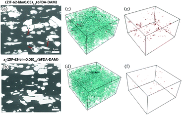
The cross-sectional morphology of the composite films was examined with scanning electron microscopy (SEM), after being fractured in liquid nitrogen (Fig. S9, ESI†). For the (ZIF-62)0.2(6FDA-DAM)0.8, interfacial defects are observed for the fractured sample. These become more evident with higher filler loading due to aggregation of the ZIF-62 filler. After thermal treatment however, the interfaces between the agZIF-62 and polyimide phases are much smoother. To further achieve more comprehensive structural information, the spatial distribution of fillers, voids and matrices for (ZIF-62)0.2(6FDA-DAM)0.8 and (agZIF-62)0.2(6FDA-DAM)0.8 were examined by focused ion beam SEM (FIB-SEM, Fig. 3). The segmentation of the individual phases (filler, void and polymer phase) was conducted via image thresholding.28,29 More information can be found in the ESI† (Fig. S10, S11 and Table S1, ESI†). For the (ZIF-62)0.2(6FDA-DAM)0.8, the presence of pinholes can be observed at the MOF/polymer interface, and within MOF aggregates, as suggested by the cross-sectional 2D image obtained under back-scattered electron mode (Fig. 3a). After in situ melting, a significant reduction in number and size of pinholes is observed (Fig. 3a and b). This is further confirmed by 3D surface-rendered views of the MOF fillers (cyan) and voids (red) (Fig. 3c–f). The volume fraction of voids reduces by 79% after thermal treatment (Table S2, ESI†), which indicates the flowing liquid MOF state is very effective in reducing meso- and macroscale defects.
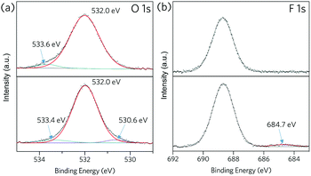
Zn 2p X-ray photoelectron spectra (XPS) of ZIF-62-bIm0.05 exhibit two intense peaks at around 1021 and 1044 eV (Fig. S12, ESI†), which correspond to the 2p3/2 and 2p1/2 components respectively. Both peaks slightly shift towards higher binding energy after the vitrification, which could be attributed to the change of Zn oxidation state because of the formation of undercoordinated metal sites after the vitrification. For (ZIF-62)0.2(6FDA-DAM)0.8 (Fig. 4), peaks at around 532 and 533 eV in the O 1s spectra are attributed to C![[double bond, length as m-dash]](https://www.rsc.org/images/entities/char_e001.gif) O and C–O groups in 6FDA-DAM.30 A new fitted peak at 530.6 eV appears in the spectrum of (agZIF-62)0.2(6FDA-DAM)0.8, which may indicate some Zn–O bonding.31 In addition, the emerging peak at 684.7 eV in F 1s spectrum after thermal treatment may indicate the formation of Zn–F bonds.32 Such an observation align with the Zn LMM Auger spectra for composite membrane before and after in situ melting (Fig. S14, ESI†). These XPS results indicate that melting of ZIF-62 within the polyimide matrix may occur alongside binding of Zn to both O and F from the 6FDA-DAM matrix.
O and C–O groups in 6FDA-DAM.30 A new fitted peak at 530.6 eV appears in the spectrum of (agZIF-62)0.2(6FDA-DAM)0.8, which may indicate some Zn–O bonding.31 In addition, the emerging peak at 684.7 eV in F 1s spectrum after thermal treatment may indicate the formation of Zn–F bonds.32 Such an observation align with the Zn LMM Auger spectra for composite membrane before and after in situ melting (Fig. S14, ESI†). These XPS results indicate that melting of ZIF-62 within the polyimide matrix may occur alongside binding of Zn to both O and F from the 6FDA-DAM matrix.
 | ||
| Fig. 4 XPS spectra for (ZIF-62)0.2(6FDA-DAM)0.8 (top) and (agZIF-62)0.1(6FDA-DAM)0.8 (bottom), (a): O 1s, (b): F 1s. | ||
The formation of new interfacial coordinative bonds can effectively promote the rigidity of polymeric matrix, which was probed by DSC (Fig. S15, ESI†). For the (agZIF-62)x(6FDA-DAM)1−x composite, one major glass transition (Tg) can be identified at ca. 390 °C. The Tg of agZIF-62-bIm0.05, which sits ca. 300 °C in its pure phase (Fig. S16, ESI†), is unobservable.24 The Tg at ca. 390 °C is assigned to the polymer matrix, reveals the change of polymeric chain rigidity. Compared with the pure 6FDA-DAM (375.4 °C), the in situ melting of ZIF-62 in this case slightly raises the Tg for the substrates: 387.4 °C for (agZIF-62)0.1(6FDA-DAM)0.9, 393.3 °C for (agZIF-62)0.2(6FDA-DAM)0.8 and 388.8 °C for (agZIF-62)0.3(6FDA-DAM)0.7 (Table S3, ESI†). This suggests an enhanced stiffness and restricted motion of the polymer chains.33
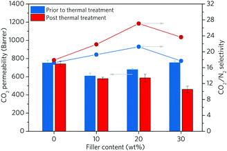
To further study the change of composite properties after in situ ZIF melting, the gas separation performance of the composite was measured with CO2 and N2 (Fig. 5 and Table S4, ESI†). The pristine 6FDA-DAM membrane shows a CO2 permeability of 752.0 Barrer with a CO2/N2 selectivity of 17.2. The addition of up to 20 wt% of crystalline ZIF-62-bIm0.05 leads to a slightly decreased CO2 permeability accompanied with a marginal enhancement (ca. 10%) in selectivity. This is consistent with the presence of ZIF-62, which occupies the free volume between the 6FDA-DAM chains, reducing the gas diffusion through the membrane. The solubility and the sorption affinity of the membrane for CO2 can be increased over N2, as demonstrated by the low adsorption capability of ZIF-62 for N2 at 303 K (Fig. S6, ESI†). As a result, the (ZIF-62)0.2(6FDA-DAM)0.8 displays a greater selectivity compared to the neat polymer membrane. Further increase in filler loading was observed to lead to lower selectivities, ascribed to the formation of interfacial voids.
We then studied the effect of thermal treatment on membrane performance. In the case of (agZIF-62)x(6FDA-DAM)1−x, all membranes present decreased CO2 permeability, with a significantly enhanced selectivity. For example, despite a lowering in CO2 permeability of ca. 22%, the (agZIF-62)0.2(6FDA-DAM)0.8 displays a 57% increase in CO2/N2 selectivity with compared to the pure polymer membrane after the thermal treatment. Compared with (ZIF-62)0.2(6FDA-DAM)0.8, (agZIF-62)0.2(6FDA-DAM)0.8 exhibits a 23.7% increase in CO2/N2 selectivity with only a 13.5% decrease in CO2 permeability. The melting of ZIF-62 significantly enhances the interfacial interaction between agZIF-62-bIm0.05 and polymer matrices, which reduces nonselective interfacial voids and rigidifies the polymer chains. Furthermore, agZIF-62-bIm0.05 exhibits extremely low uptake of N2 and very high CO2/N2 sorption selectivity at membrane operation temperature (303 K), the presence of agZIF-62-bIm0.05 enhances the difference of solubility and sorption affinity for CO2 over N2, benefiting the higher selectivity of membranes.
In summary, the application of glassy MOFs are only starting to be explored, and this study demonstrates the proof of concept of in situ fabrication of glassy MOF/polymer composite. ZIF-62 crystals have been shown to undergo melting within polymeric matrices. The array of experimental characterisations shows the in situ melting within matrics effectively heals the defects even at meso- and macroscale. The dynamically under-coordinated metal nodes and organic ligands in the liquid phase conformation form bonds with polymeric matrices, rigidifying the polymer chains. These findings are encapsulated by membrane molecular separation performances, revealing that the in situ melting effectively promotes the membrane selectivity. This results presented here, together with recent progress on fabricating hybrid glass MOF and composite glass MOFs,34,35 may provide further insights into the huge potential of glassy MOF based composites, such as solid electrolytes, ion conduction, and catalysis.
JH gratefully acknowledges UQ ECR Grant (UQECR2057677) and Australian Research Council Discovery Early Career Award (DE190100803). TDB thanks the Royal Society for a University Research Fellowship (UF150021) and a research grant (RSG\R1\180395). TDB also acknowledges the Leverhulme Trust for a Philip Leverhulme Prize, and the University of Canterbury Te Whare Wānanga o Waitaha, New Zealand, for a University of Cambridge Visiting Canterbury Fellowship. VC acknowledges the Australian Research Council's Discovery Projects funding scheme (DP180103874). The authors acknowledge the facilities, and the scientific and technical assistance, of the Australian Microscopy & Micro-analysis Research Facility at the Centre for Microscopy and Microanalysis, the University of Queensland.
Conflicts of interest
There are no conflicts to declare.Notes and references
- J. Yu, C. Mu, B. Yan, X. Qin, C. Shen, H. Xue and H. Pang, Mater. Horiz., 2017, 4, 557–569 RSC.
- M.-X. Wu and Y.-W. Yang, Adv. Mater., 2017, 29, 1606134 CrossRef PubMed.
- H. Kim, S. Yang, S. R. Rao, S. Narayanan, E. A. Kapustin, H. Furukawa, A. S. Umans, O. M. Yaghi and E. N. Wang, Science, 2017, 356, 430–434 CrossRef CAS PubMed.
- T. Tian, Z. Zeng, D. Vulpe, M. E. Casco, G. Divitini, P. A. Midgley, J. Silvestre-Albero, J.-C. Tan, P. Z. Moghadam and D. Fairen-Jimenez, Nat. Mater., 2018, 17, 174–179 CrossRef CAS PubMed.
- J. Hou, A. F. Sapnik and T. D. Bennett, Chem. Sci., 2020, 11, 310–323 RSC.
- Q. L. Zhu and Q. Xu, Chem. Soc. Rev., 2014, 43, 5468–5512 RSC.
- R. Lin, B. Hernandez, L. Ge and Z. Zhu, J. Mater. Chem. A, 2018, 6, 293–312 RSC.
- M. S. Denny, J. C. Moreton, L. Benz and S. M. Cohen, Nat. Rev. Mater., 2016, 1, 16078 CrossRef CAS.
- H. Zhu, L. Wang, X. Jie, D. Liu and Y. Cao, ACS Appl. Mater. Interfaces, 2016, 8, 22696–22704 CrossRef CAS PubMed.
- A. M. Marti, S. R. Venna, E. A. Roth, J. T. Culp and D. P. Hopkinson, ACS Appl. Mater. Interfaces, 2018, 10, 24784–24790 CrossRef CAS PubMed.
- R. Lin, L. Ge, L. Hou, E. Strounina, V. Rudolph and Z. Zhu, ACS Appl. Mater. Interfaces, 2014, 6, 5609–5618 CrossRef CAS PubMed.
- L. Ge, W. Zhou, V. Rudolph and Z. H. Zhu, J. Mater. Chem. A, 2013, 1, 6350–6358 RSC.
- W. Liang, L. Li, J. Hou, N. D. Shepherd, T. D. Bennett, D. M. D'Alessandro and V. Chen, Chem. Sci., 2018, 9, 3508–3516 RSC.
- R. Lin, L. Ge, S. Liu, V. Rudolph and Z. Zhu, ACS Appl. Mater. Interfaces, 2015, 7, 14750–14757 CrossRef CAS PubMed.
- R. Lin, L. Ge, H. Diao, V. Rudolph and Z. Zhu, ACS Appl. Mater. Interfaces, 2016, 8, 32041–32049 CrossRef CAS PubMed.
- M.-T. Vu, R. Lin, H. Diao, Z. Zhu, S. K. Bhatia and S. Smart, J. Membr. Sci., 2019, 587, 117157 CrossRef CAS.
- A. Kertik, L. H. Wee, M. Pfannmöller, S. Bals, J. A. Martens and I. F. J. Vankelecom, Energy Environ. Sci., 2017, 10, 2342–2351 RSC.
- T. D. Bennett and S. Horike, Nat. Rev. Mater., 2018, 3, 431–440 CrossRef.
- Y. Wang, H. Jin, Q. Ma, K. Mo, H. Mao, A. Feldhoff, X. Cao, Y. Li, F. Pan and Z. Jiang, Angew. Chem., Int. Ed., 2020, 59, 4365–4369 CrossRef CAS PubMed.
- R. Gaillac, P. Pullumbi, K. A. Beyer, K. W. Chapman, D. A. Keen, T. D. Bennett and F.-X. Coudert, Nat. Mater., 2017, 16, 1149–1154 CrossRef CAS PubMed.
- J. Hou, C. W. Ashling, S. M. Collins, A. Krajnc, C. Zhou, L. Longley, D. N. Johnstone, P. A. Chater, S. Li, M.-V. Coulet, P. L. Llewellyn, F.-X. Coudert, D. A. Keen, P. A. Midgley, G. Mali, V. Chen and T. D. Bennett, Nat. Commun., 2019, 10, 2580 CrossRef PubMed.
- J. Hou, M. L. Rios Gomez, A. Krajnc, A. McCaul, S. Li, A. M. Bumstead, A. F. Sapnik, Z. Deng, R. Lin, P. A. Chater, D. S. Keeble, D. A. Keen, D. Appadoo, B. Chan, V. Chen, G. Mali and T. D. Bennett, J. Am. Chem. Soc., 2020, 142, 3880–3890 CrossRef CAS PubMed.
- S. Li, R. Limbach, L. Longley, A. A. Shirzadi, J. C. Walmsley, D. N. Johnstone, P. A. Midgley, L. Wondraczek and T. D. Bennett, J. Am. Chem. Soc., 2019, 141, 1027–1034 CrossRef CAS PubMed.
- L. Frentzel-Beyme, M. Kloss, P. Kolodzeiski, R. Pallach and S. Henke, J. Am. Chem. Soc., 2019, 141, 12362–12371 CrossRef CAS PubMed.
- C. Zhou, L. Longley, A. Krajnc, G. J. Smales, A. Qiao, I. Erucar, C. M. Doherty, A. W. Thornton, A. J. Hill, C. W. Ashling, O. T. Qazvini, S. J. Lee, P. A. Chater, N. J. Terrill, A. J. Smith, Y. Yue, G. Mali, D. A. Keen, S. G. Telfer and T. D. Bennett, Nat. Commun., 2018, 9, 5042 CrossRef PubMed.
- L. Hamon, N. Heymans, P. L. Llewellyn, V. Guillerm, A. Ghoufi, S. Vaesen, G. Maurin, C. Serre, G. De Weireld and G. D. Pirngruber, Dalton Trans., 2012, 41, 4052–4059 RSC.
- M. Safak Boroglu and A. B. Yumru, Sep. Purif. Technol., 2017, 173, 269–279 CrossRef CAS.
- L. Ge, R. Lin, L. Wang, T. E. Rufford, B. Villacorta, S. Liu, L. X. Liu and Z. Zhu, Sep. Purif. Technol., 2017, 173, 63–71 CrossRef CAS.
- R. Lin, L. Ge, H. Diao, V. Rudolph and Z. Zhu, J. Mater. Chem. A, 2016, 4, 6084–6090 RSC.
- G. P. López, D. G. Castner and B. D. Ratner, Surf. Interface Anal., 1991, 17, 267–272 CrossRef.
- L.-J. Meng, C. P. Moreira de Sá and M. P. dos Santos, Appl. Surf. Sci., 1994, 78, 57–61 CrossRef CAS.
- H. Y. Xu, Y. C. Liu, J. G. Ma, Y. M. Luo, Y. M. Lu, D. Z. Shen, J. Y. Zhang, X. W. Fan and R. Mu, J. Phys.: Condens. Matter, 2004, 16, 5143–5150 CrossRef CAS.
- M. Valero, B. Zornoza, C. Téllez and J. Coronas, Microporous Mesoporous Mater., 2014, 192, 23–28 CrossRef CAS.
- C. W. Ashling, D. N. Johnstone, R. N. Widmer, J. Hou, S. M. Collins, A. F. Sapnik, A. M. Bumstead, P. A. Midgley, P. A. Chater, D. A. Keen and T. D. Bennett, J. Am. Chem. Soc., 2019, 141, 15641–15648 CrossRef CAS PubMed.
- L. Longley, S. M. Collins, C. Zhou, G. J. Smales, S. E. Norman, N. J. Brownbill, C. W. Ashling, P. A. Chater, R. Tovey, C.-B. Schönlieb, T. F. Headen, N. J. Terrill, Y. Yue, A. J. Smith, F. Blanc, D. A. Keen, P. A. Midgley and T. D. Bennett, Nat. Commun., 2018, 9, 2135 CrossRef PubMed.
Footnote |
| † Electronic supplementary information (ESI) available: Full experimental procedures for MOFs and composites synthesis, results of 1H NMR, TGA, DSC, SEM, adsorption, XRD and FIB. See DOI: 10.1039/d0cc00664e |
| This journal is © The Royal Society of Chemistry 2020 |


