 Open Access Article
Superhydrophobic foam prepared from high internal phase emulsion templates stabilised by oyster shell powder for oil–water separation
Chuan-ming Yu *,
Xiao-hui Zhuang,
Sheng-wei Zeng,
Qi-xing Dong,
Zhan-xin Jing,
Peng-zhi Hong and
Yong Li*
Faculty of Chemistry and Environmental Science, Guangdong Ocean University, Zhanjiang 524088, China. E-mail: yucmingdou@163.com; yongli6808@126.com
First published on 4th June 2019
Abstract
In this paper, poly(styrene-divinylbenzene) foams were synthesized using a high internal phase emulsion (HIPE) technique with Span 80 and with 900 °C calcined oyster shell powder as a co-emulsifier, 2,2′-azobisisobutyronitrile (AIBN) as an initiator and deionized water as the dispersing phase. SEM images revealed that the materials possess a hierarchical porous structure of nano/micro size, which resulted in saturated oil adsorption in only half a minute. The dispersing phase amount was investigated for its effect on adsorption. The optimized foams have 24.8–58.3 g g−1 adsorbencies for several organic solvents, and they demonstrated superhydrophobicity and excellent oleophilicity with the water contact angle (WCA) even close to 149° and oil contact angle approaching 0°. Moreover, the foams displayed high oil retention under pressure. The adsorption–centrifugation cycling results indicated high repeatability of the recovered foams. All of these features predicted the potential applications of superhydrophobic foams in oil–water separation.
1 Introduction
Since humans engaged in oil exploitation, oil spills have occurred frequently on the ocean and sometimes on land. These oil spills will not only bring huge economic losses, but also have disastrous consequences for marine fish, microbes, birds, water and climate, and even socially. As a result, oil spill accidents have initiated intense attention among the general public, politicians, chemists, and environmentalists. As a result, oil spill cleanup has become a global need in the petrochemical field.1At present, an effective approach to solve this problem has been proposed through the use of superhydrophobic and superoleophilic polymeric foams. These materials can particularly absorb oil and repel water, demonstrating also high oil absorption capacities.2–4 Therefore, a large number of polymers have been treated as oil absorbents, such as foams,5 resins,6 sponges,7 aerogels8 etc. They are placed on the oil surface of water, where they only adsorb oil selectively, and can then be recycled. So far, a lot of polyurethane and melamine foams have been reported to hopefully be applied for oil–water separation, due to their high oil adsorbencies.9,10 However, oily wastewater generally has not only free oil on the surface of the water, but also heavy oil and suspended oil, which have brought more serious challenges for oil removal.
It has been widely proved that polymers with a porous structure are suitable candidates for the removal of oil. For example, Wang11 modified a sponge with dodecanethiol and found that the sponge can absorb a series of oils from oil-in-water emulsions selectively. Zhang12–14 synthesized polystyrene foams by the polymerization of high internal phase emulsions, which were used for the separation of oil from oil-spill water. Furthermore, they added Fe3O4 nanoparticles to give the foams a magnetic response capacity for the magnetically driven and convenient recycling of the material. Wei15 prepared TiO2 nanoparticle loaded polyurethane foam whose surface was modified with tetradecylamine amidated graphene oxide, and it exhibited a high absorption capacity for oil and simple recovery by squeezing the oil-laden foam.
When water droplets fall onto a solid surface, water tends to diffuse toward a low energy state, forming a water contact angle (WCA) at the solid–liquid–gas three-phase interface. Different water contact angles demonstrate the wettability of solid surfaces to water. In 1805, Thomas Young16 proposed the concept of liquid contact angle and established the Young's equation to define the wettability of materials. Generally, when the water contact angle is greater than 150° and the rolling angle is less than 10°, the solid surface can be considered to be a superhydrophobic surface.17 At this point, the water droplets can stand on the superhydrophobic surface like a ball and form a water film on the contact surface completely. Studies have shown that the wettability of materials is determined by the surface morphology (surface roughness) and the intrinsic material properties (surface energy).18,19 Generally, a rougher surface and greater surface free energy produce exceptional hydrophobicity.
Oyster shells are often discarded in some coastal cities, which causes pollution to the environment and creates a huge waste of natural resources. In recent years, most studies in the literature on employing oyster shell waste have focused on biological treatment, such as traditional Chinese medicine,20 food preservatives,21 and soil fertilizer.22 Oyster shell powders (OSPs) are also utilized for the removal of phosphorus,23 arsenic,24 heavy metals,25–28 and dyes.29,30 However, none of them focused on oil removal of OSP for oily wastewater.
Based on the above situation, superhydrophobic poly(styrene-divinylbenzene) foams with interconnected porous structures were prepared by the HIPE method in a one-step process. This method was accessible and convenient because the foams were generated without freezing, vacuum drying, or some other complex procedures. Additionally, calcined superfine OSP was employed to stabilize the emulsions with Span 80 as the co-surfactant in a Pickering emulsifier system, and to improve the hydrophobicity due to the formation of the multilevel pore structures. Different foams prepared with various disperse phase amounts demonstrate diverse oil adsorption features. Besides, the floating or heavy oil removal from water and recyclability of the foams were also investigated in detail.
2 Experimental
2.1 Chemicals and materials
Chemicals used in the paper were purchased from Aladdin-e Reagent Co. Ltd., Shanghai and Lingfeng Chemical Reagent Co. Ltd., Shanghai. Divinylbenzene (DVB) and styrene (St) were purified by washing with 5% aqueous sodium hydroxide and deionized water three times respectively, drying over anhydrous MgSO4 and distilling under vacuum. Other reagents were used without further purification.2.2 Preparation of superfine oyster shell powders (OSPs)
Oyster shells were obtained from a local coastal beach of Techeng Island, Zhanjiang. The shells were soaked in an alcohol solution after cleaning with a brush. After that, they were washed with deionized water, air-dried, and pulverized in a grinder, which was followed by cribration with a 1000 mesh sieve to produce the OSP for subsequent experiments. Finally, the OSP was calcined in a muffle furnace at 900 °C for 2 h. The surface morphology of the OSP was characterized by using scanning electron microscopy (SEM) (MIRA3, TESCAN, Czech). The SEM images of a sample were obtained by scanning using a focused beam of electrons. Before scanning, the OSP was coated by sputtering with gold under vacuum.2.3 Preparation and characterization of HIPEs
In the preparation process, the oil phase was prepared by mixing 0.03 g of OSP, 0.06 g of surfactant (Span 80) and 0.03 g of free radical emulsifier initiator (AIBN) scattered in 0.25 g of DVB and 0.25 g of St in a 20 mL Cillin bottle with ultrasonication for 10 min, which was then followed by drop-wise addition of deionized water. The system (the weight ratio of deionized water is around 90.6–96.7%) was dramatically shaken by hand after addition of each batch of water until sticky and compatible HIPEs were formed. Then, the emulsions were placed in a loft drier. The organic monomers polymerized at 60 °C for 10 h. The obtained regular foams were treated at 50 °C for another 10 h. After that, the obtained solid foams were treated via Soxhlet extraction with absolute ethyl alcohol for 12 h and dried to a constant mass in a drying cabinet for removal of residual surfactant and monomers. The microstructures of the materials were also investigated using SEM (MIRA3, TESCAN, Czech) with an accelerating voltage of 5.0 kV. Pore size distribution of the foam was obtained by using mercury porosimetry (Autopore IV, Micromeritics, USA). The contact angle of the foams was recorded by using a commercial XG-CAM7.1 optical system by the sessile drop method. The volumes of the droplets used in the experiments were about 5 ± 0.3 μL and at least three different spots on the same sample surface were taken for contact angle measurements (XG-CAMB3) to receive a mean value.2.4 Oil adsorbency
The oil adsorbencies of the porous foams toward chloroform, dichloromethane, diesel, peanut oil, ethyl acetate, and cyclohexane were determined. Approximately 0.1 g of dried sample in cylindrical shape was put into the oil. After adsorption saturation, the monolithic polymer was picked up from the oil, and the total mass was obtained. The oil adsorbency was calculated according to the following equation:where K represents the oil adsorbency, m1 is the weight of the sample after saturation adsorption of oil, and m0 is the weight of the original dried sample. For each sample, triplicate measurements were conducted and the average value was calculated as the final oil adsorbency.
2.5 Oil retention
The fully oil-adsorbed porous foams, weighed as m1, were centrifuged at the speed of 2500 rpm for 5 min, and then the foams were weighed as m2. The oil retention was calculated according to the following equation:2.6 Regeneration
The dried foam was immersed in oil to reach saturated oil adsorbency at room temperature, which was followed by a simple centrifugation for the removal of oil, and then it was directly subjected to a retest of oil adsorbency.3 Results and discussion
3.1 The morphology of OSP and foams
After calcination, the OSPs were spherical particles with the sizes ranging from 1 μm to 2 μm. As shown in Fig. 2(a), three emulsion samples were prepared according to Table 1. It was found that the water-in-oil emulsions would not steadily exist without Span 80, and three zones of solid, water and emulsion existed independently. Similarly, even when the amount of water is so small as 2 mL, a small content of Span 80 alone does not allow the oil and water to form a stable emulsion. But, a little bit of OSP and Span 80 allow 18 mL of water to form HIPEs (Emul 1) with 0.5 g (∼0.55 mL) of oil. Therefore, OSP and Span 80 stabilize this high internal phase emulsion method as a co-Pickering emulsifier system that will retard the gravity and capillary drainage of the emulsions. For evaluating the stability of the HIPEs, the prepared HIPEs were stored at room temperature statically. From Fig. 2, it can be seen that the HIPEs were stable for four days and it was foreseeable that this steady state will continue. At the same time, more OSP precipitated in Emul 2 while more water was generated from Emul 3. Moreover, the addition of OSP in this paper also contributed to improving the coarseness, which will help to increase the hydrophobicity of the material.14 As shown in Fig. 1(c), the obtained HIPEs look like jelly and could not flow.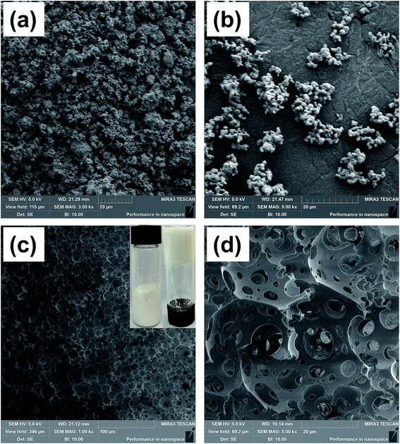 | ||
| Fig. 1 SEM images of (a) OSP before calcination, (b) OSP after calcination at 900 °C, (c) foam, and an (d) enlarged view of (c). | ||
 | ||
| Fig. 2 The optical images of emulsions at different storage times. (a) On first day. (b) After 2 days. (c) After 4 days. | ||
In short, the OSP exhibited the features of homogeneous size and morphology together with rough surfaces. These characteristics made it easier for the OSP to be attracted to the interface between water and organic monomers, which played a substantial role in sustaining the emulsions and promoting the construction of homogeneous water droplets in the system.
During the preparation of the HIPEs, a great deal of water was dispersed in the emulsions with the support of Span 80 and OSP, resulting in the construction of a stable water-in-oil system. After that, the organic continuous phase DVB and St polymerized at 60 °C, forming a cellular structure of the HIPEs. Highly porous polyHIPE foams were finally obtained after the removal of water, as shown in Fig. 1(c) and (d). This type of cellular structure is called a multi-order pore structure. The thick polymer frameworks were connected to each other constructing large spherical voids (first-order pore structure) among them. And there were some smaller windows (second-order pore structure) in the frameworks. This indicates that the pores inside the foam are connected to each other. It is believed that the thin organic film shrunk at the polymerization gel moment, which led to the formation of windows between contiguous voids.31,32 Besides, it is a universal phenomenon in polymer chemistry that retraction during polymerization causes the formation of interconnected pores.
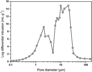
In the preparation, an increase in the water capacity was found to cause an obvious increase in the void volume of the resulting polymer materials, while the density of the material significantly decreased from 0.089 g cm−3 to 0.035 g cm−3. This phenomenon was interrelated with the original compositions of the emulsions from which they were fabricated. Pores in the foam were generated from the water drops in the emulsions before polymerization.33 As a result, a higher water content led to the formation of a higher void capacity of the materials. Hence, the internal structures and densities of the resulting foams can be adjusted by the water content, which is listed in Table 2. The measured sample densities are always smaller than the theoretical densities. A possible explanation is that the unreacted or less polymerized monomer in the ethanol extraction process is dissolved in the ethanol solution, resulting in a lower actual mass than the theoretical mass. Furthermore, the pore size distribution of sample 7 was obtained by using mercury intrusion instruments, and three palpable peaks could be found, as shown in Fig. 3. The peaks at around 10 μm and 20 μm were mainly ascribed to the holes, whereas the peak at around 2 μm was attributed to the windows in the skeleton of the holes. In addition, the pore size distribution result correlated well with the SEM image. It is believed that sample 7 possesses an open-pore structure, which is consistent with Joel M. Williams' opinion that when Span 80 comprises more than 7% of the monomer, small windows will be formed.34 Here, the mass ratio of Span 80 reaches 12% of the monomer. This will make the thickness of the oil phase film thinner, which in turn causes the polymer film to crack at the weakest point to form through-holes.
| Samples | Water/mL | Density/g cm−3 | Porosity | |
|---|---|---|---|---|
| Theor.a | exptlb | Theor.c | ||
| a Theoretical density: calculated based on the total volume of water and oil, and the total mass of oil and OSP.b Experimental density: calculated based on the measured weight and volume.c Theoretical porosity: calculated based on the volume of used water and oil. | ||||
| 1 | 6 | 0.102 | 0.089 | 90.1 |
| 2 | 8 | 0.078 | 0.068 | 92.4 |
| 3 | 10 | 0.063 | 0.058 | 93.8 |
| 4 | 12 | 0.054 | 0.047 | 94.8 |
| 5 | 14 | 0.046 | 0.041 | 95.5 |
| 6 | 16 | 0.041 | 0.038 | 96.0 |
| 7 | 18 | 0.036 | 0.035 | 96.4 |
3.2 The hydrophobicity and lipophilicity of foams
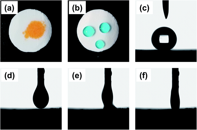
The polymer foam exhibited excellent oleophilicity with the contact angle between ethyl acetate and the material surface close to 0°. When a drop of ethyl acetate (dyed with Sudan II) was dripped on the monolithic surface, it was quickly adsorbed, as shown in Fig. 4(d–f). The droplet began to contact the foam at 0 ms, and it was adsorbed absolutely by the material in about 66 ms, indicating the kind lipophilicity of the obtained foam. Furthermore, the foam exhibited superb hydrophobicity with a WCA equivalent to 149° (Fig. 4(c)). As shown in Fig. 4(b), the water-drop (dyed with methylene blue) could absolutely stand on the foam like a sphere that would easily slip off when subjected to a slight external force or imbalance with an angle more than 7°. As a result, the foam could adsorb oil selectively from water based on the impressive hydrophobicity and lipophilicity.3.3 The application in oil–water separation
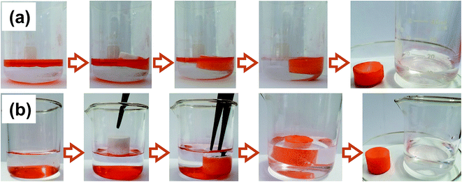
To investigate the application value of the oil-adsorbing foam in the field of oil–water separation, the removal experiments of oil spill and underwater heavy oil were demonstrated with ethyl acetate and dichloromethane dyed by Sudan II as the oil pollution model, respectively. 10 mL of ethyl acetate was placed on top of the water layer, and a regular cut foam was added. It was observed that the foam promptly adsorbed the oil and the water sample returned to clear, as shown in Fig. 5(a). Similarly, 10 mL of dyed dichloromethane was introduced under the water surface and the foam was added. It was found that the foam floats on the water surface due to its low density and porous structure. The material palpably repelled water when immersed below the water via tweezers. Once in contact with the bottom oil, the foam immediately adsorbed the oil and discharged the internal air until the oil was adsorbed to saturation in several seconds, meanwhile, a clean water sample was finally obtained, as shown in Fig. 5(b). The above experiments further indicated that the prepared foam has excellent lipophilicity and hydrophobicity, and that it showed potential to be applied in sudden oil spill accidents and the purification of oily wastewater.3.4 Oil adsorbency and adsorption kinetics
Saturated oil adsorption capacity is a core feature for application in oil–water separation. As shown in Fig. 6(a), the largest oil adsorbencies of the polymer foam towards chloroform, dichloromethane, diesel, peanut oil, ethyl acetate, and cyclohexane were 58.3, 43.2, 40.3, 36.9, 30.9 and 24.8 g g−1, respectively. These adsorption capacities were higher than those of similar reported functional materials.35,36 The obtained foams prepared by modifying the amount of dispersed phase water (ranging from 6 mL to 18 mL) displayed significantly different oil adsorption capacities. It was clear that the oil adsorption of the foam gradually improved with the increase of water consumption. This was because the obtained foams were prepared from a water-in-oil emulsion in which the organic phase was polymerized to form the skeleton and the aqueous phase was dried to become the voids of the foam. More water enabled the formation of larger pores and thus a greater oil adsorption capacity. However, it should be noted that excess water will cause the demulsification of HIPEs. Therefore, 18 mL (36 times the weight of the monomers) of water was the most suitable amount for this study.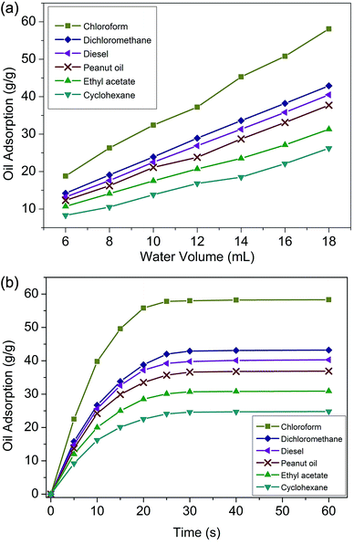 | ||
| Fig. 6 (a) Oil adsorption of foams with different amounts of water; (b) adsorption kinetics of foams. | ||
It has been reported that the driving force for oil adsorption is chiefly the capillary force interactions and van der Waals force between the polymer molecules and oil droplets, and as a result, the foams were designed to be hydrophobic. On the other hand, on the basis of Flory's swelling theory, adsorption behaviour is influenced by such features as specific surface area, void volume and structure.37 Fig. 6(b) presents the adsorption kinetics curves.
The foam adsorbed oil quickly in the first 10 seconds. After that, the oil adsorption rate gradually slowed down, tended to balance, and reached adsorption saturation in about 30 seconds. For some nanoporous resins, more than 30 min was needed to achieve oil adsorption saturation.38 In this study, the rapid adsorption speed was quite an individual characteristic, which was due to the perforated multi-order pore structure and the superb lipophilicity.39
3.5 Oil retention and reusability
High oil retention is another feature of oil-adsorption foams for emergency oil treatment. Fig. 7(a) displays the desorption of oil from the foams via centrifugation at the speed of 2500 rpm for 5 min. During the adsorption–centrifugation experiments, ethyl acetate was chosen as the oil model to measure the oil retention due to its hypotoxicity. The oil retention of the prepared foams with different dosages of disperse phase, calculated by the above formula, was over 90%. This indicated that most of the adsorbed oil could be kept in the foams even under pressure. The regenerated foam was sequentially used for the next cycle of ethyl acetate adsorption, and the oil adsorption capacities in different cycles are presented in Fig. 7(b). It was observed that there was little decline of oil adsorbency after 10 cycles of adsorption and desorption. What couldn't be ignored is that there was always the same amount of residual oil left in the foam after each centrifugation. It was speculated that the residue was tightly sandwiched in tiny pores. As a result, the obtained foam demonstrated the desired oil retention rate and recycling performance, which gave it promise to achieve practical application.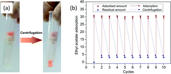 | ||
| Fig. 7 (a) Centrifugation for the extraction of ethyl acetate (dyed with Sudan II for clear observation); (b) oil adsorption capacities in different cycles. | ||
4 Conclusions
In summary, alveolate poly(St-DVB) foams were synthesized from high internal phase emulsions that were co-stabilized by superfine spherical OSP and Span 80 in a one-step process. The organic composite foam exhibits favorable superhydrophobicity with the WCA approaching 149° because of the low surface energy and high rugosity. The perforated multi-order porous structures at the micro–nanometre level contributed to the superb oleophilicity, which enabled the foam to achieve saturated adsorption in only 30 seconds. The adsorption capacities of the optimized porous foams toward several oil models were as high as 24.8–58.3 g g−1. The oil–water experiments indicated that the foams could remove both light and heavy oils from water. The further cycling experiments demonstrated that the composite materials were stable in retaining the oil and displayed little deterioration after 10 cycles of adsorption–centrifugation. In conclusion, all the above features made it particularly effective in the application of oil–water separation.Conflicts of interest
There are no conflicts to declare.Acknowledgements
This research was supported by College Youth Innovation Talents Project of Guangdong Province (2017KQNCX093), Science and Technology Plan Project of Zhanjiang City (2017A02016 and 2018A01042), Program for Scientific Research Start-up Funds of Guangdong Ocean University (R18018), and College Students Innovation and Entrepreneurship Training Program of Guangdong Ocean University (CXXL2018108, CXXL2019300, and CXXL2019301). We also appreciate Mrs He for the photography using SEM.References
- S. Barroso-Solares, J. Pinto, D. Fragouli and A. Athanassiou, Materials, 2018, 11, 2382 CrossRef PubMed.
- L. Liu, J. Lei, L. Li, R. Zhang, N. Mi, H. Chen, D. Huang and N. Li, Mater. Lett., 2017, 195, 66–70 CrossRef CAS.
- J. Pinto, A. Athanassiou and D. Fragouli, J. Environ. Manage., 2018, 206, 872–889 CrossRef CAS PubMed.
- J. Tan, W. Li, C. Ma, Q. Wu, Z. Xu and S. Liu, Materials, 2018, 11, 1106–1117 CrossRef PubMed.
- T. Zhang, L. Kong, Y. Dai, X. Yue, J. Rong, F. Qiu and J. Pan, Chem. Eng. J., 2016, 309, 7–14 CrossRef.
- X. Yue, T. Zhang, D. Yang, F. Qiu, J. Rong, J. Xu and J. Fang, Chem. Eng. J., 2017, 309, 522–531 CrossRef CAS.
- S. Zhou, G. Hao, X. Zhou, W. Jiang, T. Wang, N. Zhang and L. Yu, Chem. Eng. J., 2016, 302, 155–162 CrossRef CAS.
- M. N. Temnikov, Y. N. Kononevich, I. B. Meshkov, M. I. Buzin, V. G. Vasil'ev, G. G. Nikiforva and A. M. Muzafarov, Polymer, 2018, 138, 255–266 CrossRef CAS.
- J. Wang, W. Yang, F. He, C. Xie, J. Fan, J. Wu and K. Zhang, Chem. Lett., 2018, 47, 414–416 CrossRef CAS.
- T. Zhang, L. Kong, M. Zhang, F. Qiu, J. Rong and J. Pan, RSC Adv., 2016, 6, 86510–86519 RSC.
- J. T. Wang, H. F. Wang and G. H. Geng, Mar. Pollut. Bull., 2018, 127, 108–116 CrossRef CAS PubMed.
- N. Zhang, Y. Zhou, Y. Zhang, W. Jiang, T. Wang and J. Fu, Chem. Eng. J., 2018, 354, 245–253 CrossRef CAS.
- N. Zhang, S. Zhong, X. Zhou, W. Jiang, T. Wang and J. Fu, Chem. Eng. J., 2016, 298, 117–124 CrossRef CAS.
- N. Zhang, S. Zhong, T. Chen, Y. Zhou and W. Jiang, RSC Adv., 2017, 7, 22946–22953 RSC.
- Q. Wei, O. Oribayo, X. Feng, G. L. Rempel and Q. Pan, Ind. Eng. Chem. Res., 2018, 57, 8918–8926 CrossRef CAS.
- T. Young, Philos. Trans. R. Soc. London, 1805, 95, 65–87 CrossRef.
- Y. Si and Z. Guo, Nanoscale, 2015, 7, 5922–5946 RSC.
- M. Liu, S. Wang and L. Jiang, Nat. Rev. Mater., 2017, 2, 17036–17052 CrossRef CAS.
- L. Feng, S. Li, Y. Li, H. Li, L. Zhang, J. Zhai and D. Zhu, Adv. Mater., 2010, 14, 1857–1860 CrossRef.
- Y. Xue, S. Zhou, A. Ma, H. Xu, H. Huan and H. Liu, Mar. Drugs, 2012, 10, 1180–1191 CrossRef PubMed.
- Y. K. Lee, S. K. Jung, Y. H. Chang and H. S. Kwak, Int. J. Food Sci. Nutr., 2017, 68, 931–940 CrossRef CAS PubMed.
- Y. M. Awad, S. S. Lee, K. H. Kim, Y. S. Ok and Y. Kuzyakov, Chemosphere, 2018, 198, 40–48 CrossRef CAS PubMed.
- M. C. Martins, E. B. H. Santos and C. R. Marques, Sci. Total Environ., 2017, 574, 605–615 CrossRef CAS PubMed.
- L. Fan, S. Zhang, X. Zhang, H. Zhou, Z. Lu and S. Wang, J. Environ. Manage., 2015, 156, 109–114 CrossRef CAS PubMed.
- Q. Wu, J. Chen, M. Clark and Y. Yu, Appl. Surf. Sci., 2014, 311, 264–272 CrossRef CAS.
- H. Y. Yen and J. Y. Li, J. Environ. Manage., 2015, 161, 344–349 CrossRef CAS PubMed.
- H. Y. Yen, Desalin. Water Treat., 2016, 57, 20430–20438 CrossRef CAS.
- D. Alidoust, M. Kawahigashi, S. Yoshizawa, H. Sumida and M. Watanabe, J. Environ. Manage., 2015, 150, 103–110 CrossRef CAS PubMed.
- S. Y. Kazemi, P. Biparva and F. Ashtiani, Ecol. Eng., 2016, 88, 82–89 CrossRef.
- S. Jung, N. S. Heo, E. J. Kim, S. Y. Oh, H. U. Lee, I. T. Kim and Y. S. Huh, Process Saf. Environ. Prot., 2016, 102, 129–139 CrossRef CAS.
- A. Carranza, M. G. Pérez-García, K. Song, G. M. Jeha, Z. Diao, R. Jin, N. Bogdanchikova, A. F. Soltero, M. Terrones, Q. Wu, J. A. Pojman and J. D. Mota-Morales, ACS Appl. Mater. Interfaces, 2016, 8, 31295–31303 CrossRef CAS PubMed.
- N. R. Cameron, D. C. Sherrington, L. Albiston and D. P. Gregory, Colloid Polym. Sci., 1996, 274, 592–595 CrossRef CAS.
- Y. Luo, A. N. Wang and X. Gao, Soft Matter, 2012, 8, 1824–1830 RSC.
- J. M. Williams and D. A. Wrobleski, Langmuir, 1988, 4, 656–662 CrossRef CAS.
- Q. Zhu, Y. Chu, Z. Wang, N. Chen, L. Lin, F. Liu and Q. Pan, J. Mater. Chem. A, 2013, 1, 5386–5393 RSC.
- S. Yu, H. Tan, J. Wang, X. Liu and K. Zhou, ACS Appl. Mater. Interfaces, 2015, 7, 6745–6753 CrossRef CAS PubMed.
- A. M. Atta, R. A. El-Ghazawy, R. K. Farag, A. F. El-Kafrawy and A. A. A. Abdel-Azim, Polym. Int., 2005, 54, 1088–1096 CrossRef CAS.
- L. Ma, X. Luo, N. Cai, Y. Xue, S. Zhu, Z. Fu and F. Yu, Appl. Surf. Sci., 2014, 305, 186–193 CrossRef CAS.
- X. Zhou and C. Chuai, J. Appl. Polym. Sci., 2010, 115, 3321–3325 CrossRef CAS.
| This journal is © The Royal Society of Chemistry 2019 |


