 Open Access Article
Resolution enhancement in micro-XRF using image restoration techniques
Jie
Yang
 *ad,
Zhenjie
Zhang
bd and
Qiuming
Cheng
cd
aInstitute of Earth Sciences, China University of Geosciences (Beijing), Beijing, 100083, China. E-mail: sinixyang@gmail.com
bSchool of Earth Sciences and Resources, China University of Geosciences (Beijing), Beijing, 100083, China
cSchool of Earth Science and Engineering, Sun Yat-sen University, Zhuhai, 51900, China
dState Key Laboratory of Geological Processes and Mineral Resources, China University of Geosciences, Beijing, 10083, China
First published on 11th February 2022
Abstract
Micro X-ray fluorescence analysis (micro-XRF) commonly has a lower spatial (lateral) resolution than other elemental mapping techniques like scanning electron microscopy. This disadvantage limits further applications of micro-XRF in microanalysis. In this study, the spatial resolution of micro-XRF was improved by oversampling and image restoration techniques, including both blind and non-blind methods. The point spread function (PSF) for the non-blind method was estimated efficiently by applying both the small point method and the knife-edge method. Three non-blind algorithms—the fast iterative shrinkage-thresholding algorithm, the Wiener filter, and the Richardson–Lucy (RL) method—were tested. The results showed that all these methods could improve the spatial resolution by as much as 26.5%. According to two image quality metrics—the mean squared error and the structural similarity index measure—the results of the RL method were better than those of the others. Compared to the non-blind method, the blind method called “blind deblurring with L0-regularized intensity and gradient prior” only yielded a 12.3% improvement of the resolution, but it obtained a more precise estimation of the size of the PSF. An oversized PSF helps to denoise, but it might reduce the resolution, and vice versa. When the correct PSF was used in the RL method, the improvement of the resolution was as high as 41.6%. A further application on rock samples showed that the technique helped to reduce the resolution variations caused by polychromatic X-rays. This study demonstrated that this technique is promising, but it is still necessary to accumulate more data and design more appropriate algorithms for micro-XRF images.
Introduction
In recent years, an increased number of benchtop micro X-ray fluorescence analysis (micro-XRF) and macro X-ray fluorescence analysis (macro-XRF) instruments have been developed,1–5 and they have rapidly contributed to research in electronics manufacturing,6 forensic sciences,7,8 materials sciences,9 botany,10 geology,11–17 and art history.1,18–23 The main difference between micro-XRF and macro-XRF is the resolution at which the investigation is performed (typical 100 μm),24 and we only refer to micro-XRF in this paper. Micro-XRF can perform non-destructive elemental mapping on few or even non-pre-processed samples. Compared with other widely used non-destructive analysis techniques, such as electron probe microanalysis (EPMA) and scanning electron microscopy (SEM), the micro-XRF apparatus has a simpler structure, does not require peripheral equipment (e.g., devices for cutting, coating, and polishing), and has a lower maintenance cost. Overall, the cost of the technique is low, and the process is user friendly. However, the X-ray fluorescence analysis (XRF) image has a lower spatial (lateral) resolution than SEM or EPMA images. This is because most micro-XRF instruments use a capillary or a polycapillary for X-ray optics.25 Consequently, the beam size of the X-ray on the focus plane is a few tens of microns (typical 10–50 μm), while the electron beam size in typical SEM and EPMA is commonly less than or close to one micron.26 As a result, the elemental mapping resolution of micro-XRF is of the order of tens of microns, and the resolution of SEM or EPMA is of the order of sub-microns to a few microns.27 For this reason, although micro-XRF is more convenient to use, SEM and EPMA still have a significant competitive edge over micro-XRF for acquiring high-resolution elemental images.Therefore, the improvement of the spatial resolution is essential for micro-XRF mapping. The most straightforward approach is to improve the hardware of the instruments, including reducing the beam size of the X-ray and decreasing the detector input aperture,28 but these are not easy tasks. An alternative method is tuning the mapping parameters like the step size and the dwell time.27 In addition, up-sampling algorithms such as super-resolution can improve the resolution of XRF images. A few studies have been devoted to this approach in the past few years. Dai et al. proposed dictionary learning, total variation super-resolution, and deep learning methods to address this problem.29–31 However, those methods rely on trainings with an accumulation of data, and it is not easy to apply an algorithm that is trained on a given image type to another image type. According to the Shannon–Nyquist sampling theorem, the upper limit of the resolution should be half the sampling frequency.27 For most micro-XRF instruments, the minimum available mapping steps are much smaller than the X-ray spot size. Therefore, an over-sampling image with higher pixel counts can be acquired by using a dwell step smaller than the spot size, and the over-sampled image would have a higher spatial resolution. However, with this approach, the resolution improvements are much smaller than the limit the Shannon–Nyquist sampling theorem permitted. When the step size is smaller than 1/4 of the spot size, the resolution can be improved only by 70%.27 However, the over-sampling image can be regarded as the convolution of the X-ray fluorescence spot and the high-resolution image. Therefore, it is possible to restore the image via image restoration techniques (Fig. 1). The study by Sorokoletov verified this theory and showed that the variational Tikhonov regularization algorithm could improve the resolution in one-dimensional scanning micro-XRF analysis.32 In this paper, several classical image restoration techniques are introduced, applied, and compared to improve the spatial resolution of XRF images.
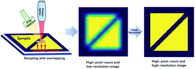 | ||
| Fig. 1 Diagram of acquiring a high-resolution image with over-sampling mapping and image restoration techniques. | ||
Image restoration techniques
Basics of image restoration
Image restoration has a long history beginning in the 1950s.33 Numerous new deblurring and denoising algorithms are proposed every year, and the field has been rapidly growing recently due to the increase of market demand (e.g., phone photography and computational photography) and the boom of deep learning.34,35 An ideal convolution processing in XRF mapping can be represented as follows:| y = h*x, |
| Y = HX, |
| X = Y/H. |
However, this approach does not work well because noise ε is usually involved in the convolution process, that is,
| y = h*x + ε. |
In the convolution process, the power of the high-frequency signal decreases to almost zero. If we try to restore the image by an inverse process, the high-frequency signals will be amplified significantly. However, because noise also appears at high frequencies, this process will lead to extremely noisy results. Unfortunately, XRF images are usually highly noisy; in this case, iterative methods are more suitable for restoring XRF images. Therefore, a common solution for the problem is using a least squares (LS) approach to find a solution ![[x with combining tilde]](https://www.rsc.org/images/entities/i_char_0078_0303.gif) that can minimize the error, that is,
that can minimize the error, that is,
![[x with combining tilde]](https://www.rsc.org/images/entities/i_char_0078_0303.gif) = argminx‖h*x − y‖2. = argminx‖h*x − y‖2. |
For image deblurring, the inverse problem is usually ill-conditioned. To overcome this difficulty, regularization w(x) with priors is required to stabilize the solution.36 A general form is
![[x with combining tilde]](https://www.rsc.org/images/entities/i_char_0078_0303.gif) = argminx{‖h*x − y‖2 + w(x)}. = argminx{‖h*x − y‖2 + w(x)}. |
For example, one popular regularization technique is the Tikhonov regularization, in which a quadratic penalty is added:37
![[x with combining tilde]](https://www.rsc.org/images/entities/i_char_0078_0303.gif) TIK = argminx{‖h*x − y‖2 + λ‖Lx‖2}. TIK = argminx{‖h*x − y‖2 + λ‖Lx‖2}. |
The second term is an l2 regularization term, and the parameter λ controls the balance between the fidelity and noise. Common choices for L are the identity matrix or a matrix approximating the first- or second-order derivative operator. When the PSF is known, the restoration technique is called a non-blind method; otherwise, it is called a blind method. For the blind case, stronger prior assumptions should be added to constrain both the restored image and the PSF, which are output as the results.
Wiener deconvolution
The most classical non-blind deconvolution method is the Wiener filter (WF). It solves the image deconvolution problem in the Fourier domain. The Fourier transform of the restored image![[X with combining tilde]](https://www.rsc.org/images/entities/i_char_0058_0303.gif) can be obtained as follows:
can be obtained as follows:where H′ is the conjugate matrix of H and SNR is the signal-to-noise ratio of the image x. The SNR is difficult to estimate, and the standard WF is very sensitive to high-frequency noise. A commonly used modification is to use λ|Q|2 to replace 1/SNR. Q is a criterion matrix, which usually uses the Laplacian matrix to penalize high-frequency components, and the parameter λ tunes the balance between the data and the regularization.
Richardson–Lucy method
Due to the quantum effect of the photoelectric process, photons detected by the detector can be described by Poisson statistics, which results in Poisson noise. The Richardson–Lucy (RL) method is a maximum-likelihood method that can be used for image deblurring when the data noise is assumed to follow a Poisson distribution.38 Unlike the WF method, the RL method solves the problem in the space domain via an iterative method. In iterative processes, the restored image![[x with combining tilde]](https://www.rsc.org/images/entities/i_char_0078_0303.gif) k + 1 at step k + 1 can be calculated based on the image
k + 1 at step k + 1 can be calculated based on the image ![[x with combining tilde]](https://www.rsc.org/images/entities/i_char_0078_0303.gif) k from step k, that is,
k from step k, that is,where ĥ is the flipped matrix of h obtained by reversing the order of the elements in the rows and columns of h.
Fast iterative shrinkage-thresholding algorithm
The fast iterative shrinkage-thresholding algorithm (FISTA) is an improvement of the iterative shrinkage-thresholding algorithm (ISTA), which is an iterative algorithm with l1 regularization used to solve linear inverse problems in signal/image processing.39 The optimization objective of the ISTA or FISTA is![[x with combining tilde]](https://www.rsc.org/images/entities/i_char_0078_0303.gif) = argminx[‖h*x − y‖2 + λ‖x‖1], = argminx[‖h*x − y‖2 + λ‖x‖1], |
Blind deblurring with L0-regularized intensity and gradient prior
The above three methods are classical, non-blind methods. Since blind methods are easier to use, numerous blind methods have been proposed.40 According to the study by Lai et al.,41 an algorithm named “blind deblurring with L0-regularized intensity and gradient prior” (L0RIGP)42 is one of the best blind algorithms for single image deblurring. Based on the properties of two-tone text images, the algorithm uses an L0-regularized prior to solve the image deblurring problem. It has been demonstrated that the algorithm also effectively handles non-document text images and low-illumination scenes with saturated regions. The optimization objective of the method is![[x with combining tilde]](https://www.rsc.org/images/entities/i_char_0078_0303.gif) = argminh,x[‖h*x‖22 + γ‖h‖22 + λP(x)], = argminh,x[‖h*x‖22 + γ‖h‖22 + λP(x)], |
Benchmark
Resolution test chart
The most straightforward benchmark for testing the resolution of an optical system is a resolution test chart. The chart usually consists of many patterns in groups that progressively become smaller, and USAF 1951 was used in this study. Each group in the USAF 1951 chart consists of six elements, and each element is composed of two blocks of three parallel lines (vertical and horizontal). The resolution can be estimated by finding the smallest block in which the lines can be identified. Based on the group number (G) and element number (E), the resolution (R) denoted by line pairs per millimeter (lp mm−1) can be calculated as follows:| R = 2G+(E−1)/6. |
Because the pattern was printed in metallic chromium on a piece of glass, a low-resolution XRF image of Cr-Kα could be obtained by scanning the chart with micro-XRF. In addition, a high-resolution optical image that could be used as a reference was obtained by using a microscope. We used a version with eight groups (groups 0–7), which could test a resolution range of 0.250–912.3 lp mm−1. This resolution range is adequate for testing both XRF and optical images.
Image quality assessment
Because both high-resolution optical images and low-resolution XRF images can be achieved, some metric of image quality assessment can be used.43 The simplest measurement is the mean squared error (MSE), that is, the average squared difference between the estimated values and the actual values. A lower MSE value indicates that the image was better restored. For two images p and q with the same size of m × n, the MSE between them isAnother widely used benchmark is the structural similarity index measure (SSIM),44 which also measures the similarity between two images. Unlike the MSE based on absolute errors, the SSIM considers the structural information or the inter-dependencies between pixels that are spatially close.43 A greater value of the SSIM indicates that two images are more similar. The SSIM index is calculated on various windows of an image. The SSIM between two windows p and q of same size N × N is
XRF and optics images
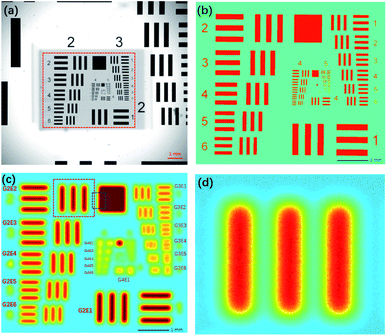
A macro-XRF instrument (Bruker M6 Jet Stream) was used to acquire XRF images.1 The instrument used an Rh target X-ray source (50 kV, 0.6 mA) and polycapillary optics, which could generate a spot size smaller than 50 μm for Mo-Kα. The X-ray beam was perpendicular to the sample surface. The silicon drift detector (SDD) had an energy spectrum resolution of 145 eV for Cr-Kα at 275 kcps. The movement accuracy in the XY-direction was 3 μm, and in the Z-direction, it was 1 μm. Since this system was not equipped with a vacuum chamber, all the analyses were performed in air. A part of the 1951 USAF chart (G2–G7) was scanned by the equipment with a step size of 5 μm and a dwelling time of 0.5 s for each pixel, and the overall scan took 42 h. The area covered by chrome had an average value of 429 cps, and the background had an average value of 275 cps. The resolution test chart was also photographed via a Lecia optical microscope with a magnification of 50×. Fig. 2a shows that the smallest pattern that could be identified was G6E6, that is, a resolution of 114.0 lp mm−1. The photograph was slightly rotated and resampled to a pixel size of 5 μm to match the XRF image. Because the pixel values of the optical image and XRF image were in different numerical ranges, to assess images via the MSE and SSIM, the numerical ranges of the two images were transformed to 0–1. The area covered by chrome had an average value of 1; elsewhere, the average value was 0.Compared to the optical image, the XRF image was fuzzier, and the patterns were blurry (Fig. 2c). The numbers on the left (2–6) could not be recognized; yet, lines in the blocks smaller than G3E4 were joined and could not be identified. Therefore, the spatial resolution of the XRF image was 11.3 lp mm−1. However, according to the Nyquist–Shannon sampling law, when the sampling distance was 5 μm, the limitation of the resolution was 100 lp mm−1, and the smallest pattern that could be identified was G6E5. The zoomed-in XRF image was highly noisy, and the lines were twisted with blurred edges (Fig. 2d). This may have been caused by current fluctuations of the X-ray tube, instability of the SDD, stage jitters, or positioning errors.
Point spread function (PSF) estimation
Point scan method
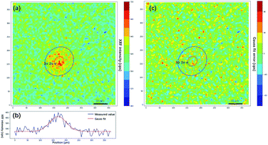
As discussed in the previous section, the PSF is essential for image restoration. For micro-XRF mapping, the PSF is similar to the intensity distribution of XRF. The most exact measurement method of X-ray beams is the pin-hole method, in which an aperture between the X-ray beam and detector is moved. This method can directly obtain the X-ray energy spectrum distribution. However, this measurement is not possible for most instruments, because it is not easy to install a metal plate (aperture) and a detector. Moreover, it is not suitable for measuring the PSF for the following reasons: (1) most X-ray sources are polychromatic, and different energy X-rays have different spot sizes. Because low-energy fluorescence can be excited by both high- and low-energy X-rays, it is not easy to calculate the XRF distribution based on the X-ray distribution when considering a variety of samples. (2) X-rays have a volume effect and scatter in a material, which changes the intensity distributions of XRF on the sample surface. Therefore, a better method is to scan a very tiny metallic dot or ball with a small step size, and the shapes of PSFs for different elements (different XRF energies) can be depicted by XRF images.A piece of glass with a 5 μm dot of Cr coating on it was scanned with a step size of 5 μm. Fig. 3a shows that the Cr-Kα XRF spot was approximately round, and the XRF intensity distribution in the horizontal direction was bell-shaped (Fig. 3b). Considering other research on X-ray beam/spot intensity distributions,28 we can roughly say that the intensity distribution of the XRF spot followed a Gaussian distribution. The PSF h(u,v) and the intensity distribution of the XRF g(u,v) can be defined as follows:
| g(u,v) = αh(u,v) + β, |
where μu and μv are the coordinates of the center of the XRF spot, σu and σv control the spot size along the u- and v-axes, respectively, ρ adjusts the ellipticity of the spot, α is a parameter controlling the maximum intensity of the XRF, and β is the level of background noise. Regression analysis was performed to obtain these parameters, and the error distribution (measured intensity minus the predicted value) is shown in Fig. 3c. The errors were evenly distributed, which implied that two-dimensional normal distribution was a good approximation for the PSF in this study. The confidence ellipse shows that the spot was not perfectly round, and its long axis was in a 45° direction, which is because the SNR was low and the total measurement time was not long enough. The sample was scanned many times in the laboratory, and the long axis swung drastically for each measurement. Therefore, since ρ was rather close to zero and the polycapillary was vertically installed, an isotropic two-dimensional Gaussian distribution was used as the PSF in the subsequent analysis.
Knife-edge method
X-ray beams are in a conical shape when emitted from polycapillary optics; therefore, the PSF changes with the distance from the focal plane. The X-rays usually are not perfectly focused during mapping, which will slightly alter the XRF intensity distribution on the surface of a sample. Although the PSF can be obtained accurately by the point scan method, the measurement is too time-consuming. A quicker and easier measurement of the PSF is necessary. Under the assumption that the change of the PSF follows an affine transformation around the focal plane, when the distribution model of the PSF is known, the PSF can be roughly estimated by measuring the spot size along one axis. For instance, in this study, an isotropic two-dimensional Gaussian was taken as the distribution model, in which ρ = 0 and σu/σv = 1. When σu or σv can be acquired, the complete PSF is known. By finding a straight edge on the sample, σu or σv can be measured quickly by the knife-edge method.The common definition of the spot size is its full width at half maximum (FWHM). For a Gaussian distribution, the FWHM is the width from 12% to 88% of the cumulative distribution function (CDF). The relation between the FWHM and the standard deviation (σ) in the Gaussian distribution is as follows:
According to the above equation, the PSF size can be quickly estimated by measuring the FWHM. However, due to the inhomogeneity of the material, a more stable estimation of the XRF intensity g(u) can be acquired from the regression model of the Gaussian distribution considering background noise β, i.e.,
In the traditional knife-edge method, a metal plate between the X-ray beam and detector is moved. Because the PSF is not a distribution of the X-ray intensity but a distribution of the XRF spot, we can modify the knife-edge method by placing the X-ray beam and detector on the same side of the metal plate, and the XRF intensity distribution on the plate edge is the CDF of the PSF. Through a series of measurements by changing the distance between the plate and focal plane, the PSF size model can be established. Due to the polychromatic nature of X-rays, different material plates should be used for different elements. In the practice mapping analysis on a given sample, the PSF size can be quickly calculated by measuring the distance between the sample and X-ray optics. Besides, there is a simpler estimation of PSF size via finding and scanning sharp edges on the sample. Theoretically, it can yield a more accurate estimation of the PSF size because the matrix effect of the sample is considered. However, due to the heterogeneity of the sample, inappropriate selections of edges might lead to failures. Here, the edge of the square (Fig. 4a) on the USAF 1951 chart is used to calculate the PSF size of the XRF image. The result showed that σ was 37.5 μm, and the spot size was 88.3 μm. In the following non-blind restoration, a two-dimensional Gaussian distribution with a standard deviation of 37.5 μm was used as the PSF.
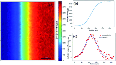 | ||
| Fig. 4 Knife edge method measurement of the size of the XRF spot. (a) XRF image of the edge of a square on USAF 1951 corresponding to the blue box in Fig. 2(c). (b) XRF intensity distribution crossing the edge. (c) XRF intensity gradient denoting the shape of the XRF spot. The red dots are gradient values of the XRF intensity, and the blue line is the curve fitted by the Gaussian model. | ||
Results
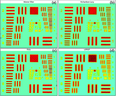
All four image restoration algorithms were tested on the raw XRF image, and the parameters of the algorithms were fine-tuned to achieve the best results. The restored images are shown in Fig. 5. All four methods significantly improved the spatial resolution. The lines and edges were sharper, and the numbers on the left (2–6) could be identified. For the three non-blind methods, the smallest pattern that could be identified was the same, G3E6 (R = 14.30 lp mm−1). According to the SSIM and MSE values, the best result was from the RL algorithm, the second was from the FISTA, and the third was from the Wiener filter. In addition, the RL image had the fewest artifacts among the three restored images. This result may have been obtained because, compared to an optical image, the Poisson noise of an XRF image is more prominent, which could be well handled by RL. The FISTA obtained a poorer result, which may have been due to the regularization in the algorithm being unsuitable for XRF images. The WF obtained the poorest result, which may have been because the model was the simplest and could not suppress high-frequency noise well.The smallest pattern in the result of L0RIGP that could be identified was G3E5, corresponding to a resolution of 12.7 lp mm−1. Therefore, in this case, the improvement of the resolution was 26.5% for non-blind methods and 12.3% for blind methods. Considering that some researchers have taken the spot size of an instrument as the spatial resolution,6 if the spot size was selected as the base value of the resolution, that is, 1000/2/88.3 = 5.66 lp mm−1, the total improvement of the spatial resolution with over-sampling mapping and restoration techniques was over 152%. However, because high-frequency signals and noise were inevitably magnified by all four algorithms, there were more artifacts in the restored image: ripples and rings occurred, and twisted lines and edges became more tortuous. With stronger regularization, the blind algorithm L0RGP produced fewer artifacts, but high frequency details in the image were significantly lost, and the background of the resulting image looked smooth.
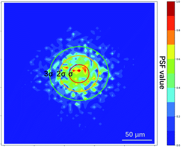
The PSF estimated by L0RIGP is shown in Fig. 6, and it was similar to the distribution of the XRF spot with a coarser surface. Based on the assumption that the distribution followed a two-dimensional Gaussian distribution, the PSF from L0RIGP had a σ value of 32.5 μm, which was smaller than the value measured by the knife-edge method.
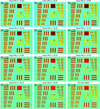
To find the optimal spot size, a series of two-dimensional Gaussian PSFs were generated with different σ values in the range of 27.5–40 μm, and then, these PSFs were applied in RL. The restored images in Fig. 7 show that when σ was close to 32.5 μm, the restored image had the highest resolution. The smallest pattern that could be identified was G4E1, corresponding to a resolution of 16 lp mm−1. Compared to the original resolution of the raw XRF image, the improvement of the resolution was 42%. With the spot size as the base of the resolution value, the overall improvement of the resolution was over 183%. This implied that L0RGP provided a more precise estimation of the PSF size than the knife-edge method, and the size estimated by the knife-edge method was slightly larger than the correct size. The over-estimation of the PSF size by the knife-edge method may have been caused by the following: (1) the edge of the square was not very sharp and the Cr coating is thin on the edge, (2) the occurrence of jitter and positioning errors during mapping, and (3) XRF noise.
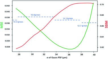
Fig. 8 shows how the MSE, SSIM and spatial resolution changed with the size of the PSF. For the MSE, the optimal σ was in the range of 35–37.5 μm, and for the SSIM, that range was 36.25–40 μm. With the spatial resolution as the criterion, the PSFs that had σ values in the range of 27.5–33.75 μm achieved the best result, and all of them had a resolution of 16 lp mm−1. The optimal σ ranges for MSE, SSIM and resolution were inconsonant, PSF with larger spot size tends to result in better MSE and SSIM values. This was because the MSE and SSIM are sensitive to noise. An improvement of the PSF size could reduce the weights of the high-frequency signals, which caused the resulting image to be smoother with less high-frequency noise. According to these results, the PSF for σ = 33.75 μm resulted in the best restored image, which led to a balance between the resolution and the appearance of artifacts. Therefore, in applications of image restoration, the spot size measured by the knife-edge method can be slightly reduced to achieve a balance between the number of artifacts and the resolution. Considering that the highest spatial resolution can be achieved in a wide range value of σ (30.6 ± 3.1 μm in this case), the tuning of σ is not very rigorous.
When the raw estimated PSF from L0RGP was applied in the RL method, the restored image had a coarse surface, as shown in Fig. 7. Also, the SSIM and MSE values showed that the result obtained using the raw estimated PSF was significantly poorer than the result obtained using the Gaussian PSF. These results imply that the correct priori or distribution model of the PSF is essential for blind methods. Based on the advantages of the blind and non-blind methods, the blind method also can be used to estimate the size of a PSF, the parameters can be inputted into the PSF distribution model, and then the resulting PSF can be applied in non-blind methods.
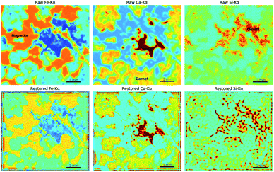
A high-quality XRF image is essential for applying image restoration methods. To acquire such an image, high-density sampling, long dwell times, and low acceleration of the stage are necessary. These raise the time cost of XRF mapping. Furthermore, the flatness of the sample, the angle of X-ray incidence, and the material of the sample might also influence the results of restoration. Thus, the application scope seems rather limited. However, image restoration methods are still useful because of the chromatic aberration of X-rays. Most micro-XRF instruments use a capillary or a polycapillary for the optics and use X-ray tubes as the X-ray source, which results in X-rays of different energies having different focus distances and spot sizes.25,45 When the X-rays of a given energy are focused, X-rays with different energies are out of focus and might have larger spot sizes. Accordingly, those XRF images are oversampled and appear blurry. For example, low-energy XRF images usually look more blurry than high-energy XRF images. Restoration techniques can improve the resolution of XRF images that are out of focus and allow XRF images with different energies to have a similar resolution. A polished iron skarn was used to demonstrate this situation. The sample consisted of magnetite (characterized by a high intensity of Fe-Kα), calcite (characterized by a high intensity of Ca-Kα), garnet (characterized by a moderate intensity of Ca-Kα), and quartz veins (characterized by a high intensity of Si-Kα). The sample was scanned by an M6 Jetstream with a step size of 10 μm. Although these crystallized minerals have sharp boundaries, their edges are blurry in XRF images (Fig. 9). As a result of the energy of Ca-Kα being smaller than that of Fe-Kα, the Ca-Kα image was blurrier than the Fe-Kα image. Because X-rays are more likely to scatter in low-atomic-number and low-density materials (e.g., quartz in this case) and low-energy X-rays are absorbed in air, the quartz distribution (denoted by the high value of Si-Kα) is dispersive. From Fe-Kα to Ca-Kα and then to Si-Kα, the resolution of the image decreased with the increase in the XRF energy. Three isotropic two-dimensional Gaussian distributions with different σ were used as the PSFs for different elements, that were 40 μm for Fe-Kα, 50 μm for Ca-Kα and 80 μm for Si-Kα. The results of RL showed that garnet, calcite, and magnetite had shaper boundaries, and the restored images of Fe-Kα and Ca-Kα had closer resolutions. However, the Si-Kα image was degraded after restoration processing, which was due to the quartz distribution being dispersive, and X-rays penetrating deeper into quartz than other minerals, and the image being highly noisy. This implies that the material and image quality are essential. Images that have extremely high noise and materials that have dispersive textures are not suitable for image restoration.
Conclusions
Non-blind and blind reconstruction methods can effectively improve the spatial resolution of oversampled XRF images. Among the four methods, RL achieved the best result. However, due to factors such as positioning accuracy and fluorescence noise, none of the methods could approach the limit of the Nyquist–Shannon law. When the non-blind method was applied, the measurement of the PSF or knowledge of the intensity distribution of the XRF spot is indispensable. The model of distribution can be determined by scanning a dot, and then, the size of the PSF can be quickly determined by the knife-edge method. However, in this way, the size of the PSF might be slightly overestimated. Because a larger PSF size can reduce the number of artifacts, a slight reduction of the measured PSF size might achieve a balance between the resolution and artifacts. Furthermore, it was demonstrated by a rock section that the techniques helped to reduce the resolution variations for different elements caused by polychromatic X-rays. This application also showed that the image restoration did not work well on images having extremely high noise and dispersive textures.Although the PSF can also be estimated from the blind method, due to a lack of a correct prior, the estimated PSF might not work well, but it has a more precise size than that obtained by a direct measurement (e.g., knife-edge method in this study). Therefore, it is possible to use a combination of measurements, a blind method, and a non-blind method to achieve a better result. Although only one blind method was reported in the paper, other blind methods proposed by Xu,46 Liu,47 and Pan48 were also tested, and the results also showed that these methods had no advantage over classical non-blind methods for improving the resolution. This may have been because there were more priors and regularizations in the blind method, which were related to images acquired by the camera. For example, Fergus found that the natural clear photographs had similar histograms of gradients, and this discovery contributed to design regularizations.49 Further studies on the patterns in XRF images are necessary for developing suitable blind methods for XRF image restoration. Nevertheless, compared to non-blind methods, blind methods are more convenient to use because they do not require measurement of the XRF intensity distribution. Moreover, in the case when the surface of a sample is not a plane, the PSF always changes on different positions. Non-blind methods with a fixed PSF are not appropriate, but some blind algorithms using non-uniform PSFs might work well.50 Therefore, the accumulation and analysis of XRF image data are required to develop suitable blind methods. Based on a large volume of data, which can be used to train machine learning models, it is possible to introduce deep learning and super-resolution techniques.35,51 These methods have been proven to be effective in micro-analysis.52 Furthermore, as an image reconstruction technique, compressive sensing was also introduced, which demonstrated the capability of acquiring high-resolution XRF images with less measuring time.53,54 It is possible to integrate these methods to obtain high-resolution XRFs more efficiently. Thus, the current investigation of image restoration methods was preliminary, and more investigation especially on blind and deep learning methods is necessary. The minimum size of the X-ray spot of benchtop micro-XRF instruments is currently approaching a few microns. If resolution enhancement technologies can be further applied, we can acquire XRF images with a spatial resolution of about 1 μm. In that case, micro-XRF will be comparable to SEM for elemental mapping, and micro-XRF will have advantages in terms of heavy element imaging capabilities,27 sample pre-processing, and maintenance costs.
Conflicts of interest
There are no conflicts to declare.Acknowledgements
The authors thank Song Lei, Yuanzhi Zhou and Bei Ye for their help in tuning the apparatus and assistance in experiments. This study was supported by the Fundamental Research Funds for the Central Universities and National Natural Science Foundation of China (No. 42050103).References
- M. Alfeld, J. V. Pedroso, M. Van Eikema Hommes, G. Van Der Snickt, G. Tauber, J. Blaas, M. Haschke, K. Erler, J. Dik and K. Janssens, J. Anal. At. Spectrom., 2013, 28, 760–767 RSC.
- F. P. Romano, C. Caliri, P. Nicotra, S. Di Martino, L. Pappalardo, F. Rizzo and H. C. Santos, J. Anal. At. Spectrom., 2017, 32, 773–781 RSC.
- J. Garrevoet, B. Vekemans, S. Bauters, A. Demey and L. Vincze, Anal. Chem., 2015, 87, 6544–6552 CrossRef CAS PubMed.
- T. Koshikawa, Y. Kido and R. Tada, J. Sediment. Res., 2003, 73, 824–829 CrossRef CAS.
- E. Pouyet, N. Barbi, H. Chopp, O. Healy, A. Katsaggelos, S. Moak, R. Mott, M. Vermeulen and M. Walton, X-Ray Spectrom., 2021, 50, 263–271 CrossRef CAS.
- S. Komatani, T. Aoyama, T. Nakazawa and K. Tsuji, e-J. Surf. Sci. Nanotechnol., 2013, 11, 133–137 CrossRef.
- K. Langstraat, A. Knijnenberg, G. Edelman, L. Van De Merwe, A. Van Loon, J. Dik and A. Van Asten, Sci. Rep., 2017, 7, 1–11 CrossRef CAS PubMed.
- K. Nakano, C. Nishi, K. Otsuki, Y. Nishiwaki and K. Tsuji, Anal. Chem., 2011, 83, 3477–3483 CrossRef CAS PubMed.
- P. Bran-Anleu, F. Caruso, T. Wangler, E. Pomjakushina and R. J. Flatt, Microchem. J., 2018, 141, 382–387 CrossRef CAS.
- V. M. Sbarato and G. E. Falchini, Anal. Methods, 2021, 10, 1280–1285 Search PubMed.
- D. Genna, D. Gaboury, L. Moore and W. U. Mueller, J. Geochem. Explor., 2011, 108, 131–142 CrossRef CAS.
- I. W. Croudace, L. Löwemark, R. Tjallingii and B. Zolitschka, Quat. Int., 2019, 514, 5–15 CrossRef.
- W. Nikonow, D. Rammlmair, J. A. Meima and M. C. Schodlok, Mineral. Petrol., 2019, 417–431 CrossRef CAS.
- J. Li, R. Pei and X. Xu, At. Spectrosc., 2020, 41, 1–11 CrossRef.
- E. R. Tharalson, T. Monecke, T. James Reynolds, L. Zeeck, K. Pfaff and N. M. Kelly, Minerals, 2019, 9(12), 740 CrossRef CAS.
- L. Germinario, R. Cossio, L. Maritan, A. Borghi and C. Mazzoli, Microsc. Microanal., 2016, 22, 690–697 CrossRef CAS PubMed.
- S. Flude, M. Haschke and M. Storey, Mineral. Mag., 2017, 81, 923–948 CrossRef CAS.
- D. MacLennan, L. Llewellyn, J. K. Delaney, K. A. Dooley, C. S. Patterson, Y. Szafran and K. Trentelman, Herit Sci., 2019, 7, 1–9 CrossRef.
- J. R. Duivenvoorden, A. Käyhkö, E. Kwakkel and J. Dik, Herit. Sci., 2017, 5, 1–10 CrossRef.
- M. Alfeld, Microsc. Microanal., 2020, 26(2), 72–75 CrossRef.
- A. Martins, J. Coddington, G. Snickt, B. Driel, C. McGlinchey, D. Dahlberg, K. Janssens and J. Dik, Herit Sci., 2016, 4, 1–13 CrossRef.
- M. Walczak, D. Tarsińska-Petruk, M. P\\lotek, M. Goryl and M. P. Kruk, X-Ray Spectrom., 2019, 48, 303–310 CrossRef CAS.
- S. Saverwyns, C. Currie and E. Lamas-Delgado, Microchem. J., 2018, 137, 139–147 CrossRef CAS.
- M. Alfeld, K. Janssens, J. Dik, W. de Nolf and G. van der Snickt, J. Anal. At. Spectrom., 2011, 26, 899 RSC.
- A. Bjeoumikhov, N. Langhoff, S. Bjeoumikhova and R. Wedell, Rev. Sci. Instrum., 2005, 76(6), 063115 CrossRef.
- J. J. Friel and C. E. Lyman, Microsc. Microanal., 2006, 12, 2–25 CrossRef CAS PubMed.
- M. Haschke, Laboratory Micro-X-Ray Fluorescence Spectroscopy, Instrumentation and Applications, 2014 Search PubMed.
- M. Dehlinger, C. Fauquet, S. Lavandier, O. Aumporn, F. Jandard, V. Arkadiev, A. Bjeoumikhov and D. Tonneau, Nanoscale Res. Lett., 2013, 8, 271 CrossRef PubMed.
- Q. Dai, E. Pouyet, O. Cossairt, M. Walton and A. K. Katsaggelos, IEEE Trans. Comput., 2017, 3, 432–444 Search PubMed.
- Q. Dai, E. Pouyet, O. Cossairt, M. Walton, F. Casadio and A. Katsaggelos, IEEE Image Video Multidimens. Signal Process. Workshop, 2016, vol. 1, pp. 1–5 Search PubMed.
- Q. Dai, H. Chopp, E. Pouyet, O. Cossairt, M. Walton and A. K. Katsaggelos, IEEE Trans. Multimedia, 2020, 22, 2564–2578 Search PubMed.
- D. S. Sorokoletov, Y. V. Rakshun, E. P. Voytovich and F. A. Darin, Phys. Procedia, 2016, 84, 295–301 CrossRef CAS.
- B. K. Gunturk and X. Li, Image Restoration: Fundamentals and Advances, 2012 Search PubMed.
- C. Belthangady and L. A. Royer, Nat. Methods, 2019, 16, 1215–1225 CrossRef CAS PubMed.
- J. Koh, J. Lee and S. Yoon, Comput. Vis. Image Underst, 2021, 203, 103134 CrossRef.
- S. Chaudhuri, R. Velmurugan and R. Rameshan, Blind Image Deconvolution, Springer International Publishing, Cham, 2014 Search PubMed.
- G. H. Golub, P. C. Hansen and D. P. O'Leary, SIAM J. Matrix Anal. Appl., 1999, 21, 185–194 CrossRef.
- M. Bertero, P. Boccacci, G. Desider and G. Vicidomini, Inverse Probl., 2009, 25(12), 123006 CrossRef.
- A. Beck and M. Teboulle, SIAM J. Imaging Sci., 2009, 2, 183–202 CrossRef.
- P. Campisi and K. Egiazarian, Blind Image Deconvolution Theory and Application, CRC Press, 2017 Search PubMed.
- W.-S. Lai, J.-B. Huang, Z. Hu, N. Ahuja and M.-H. Yang, in 2016 IEEE Conference on Computer Vision and Pattern Recognition (CVPR), IEEE, Las Vegas, NV, USA, 2016, pp. 1701–1709 Search PubMed.
- J. Pan, Z. Hu, Z. Su and M.-H. Yang, in 2014 IEEE Conference on Computer Vision and Pattern Recognition, IEEE, Columbus, OH, USA, 2014, pp. 2901–2908 Search PubMed.
- U. Sara, M. Akter and M. S. Uddin, Int. J. Comput. Commun., 2019, 07, 8–18 Search PubMed.
- Z. Wang, A. C. Bovik, H. R. Sheikh and E. P. Simoncelli, IEEE Trans. Image Process., 2004, 13, 600–612 CrossRef PubMed.
- C. A. MacDonald, X-Ray Opt. Instrum., 2010, 2010, 1–17 Search PubMed.
- L. Xu, S. Zheng and J. Jia, in 2013 IEEE Conference on Computer Vision and Pattern Recognition, IEEE, Portland, OR, USA, 2013, pp. 1107–1114 Search PubMed.
- Y. Liu, W. Dong, D. Gong, L. Zhang and Q. Shi, in Computer Vision – ECCV 2018, ed. V. Ferrari, M. Hebert, C. Sminchisescu and Y. Weiss, Springer International Publishing, Cham, 2018, vol. 11205, pp. 467–484 Search PubMed.
- L. Pan, R. Hartley, M. Liu and Y. Dai, in 2019 IEEE/CVF Conference on Computer Vision and Pattern Recognition (CVPR), IEEE, Long Beach, CA, USA, 2019, pp. 6027–6036 Search PubMed.
- R. Fergus, B. Singh, A. Hertzmann, S. T. Roweis and W. T. Freeman, Removing camera shake from a single photograph, in ACM SIGGRAPH 2006 Papers (SIGGRAPH '06), Association for Computing Machinery, New York, USA, 2006, pp. 787–794, DOI: DOI:10.1145/1179352.1141956.
- M. Hirsch, C. J. Schuler, S. Harmeling and B. Scholkopf, in 2011 International Conference on Computer Vision, IEEE, Barcelona, Spain, 2011, pp. 463–470 Search PubMed.
- Z. Wang, J. Chen and S. C. H. Hoi, IEEE Trans Pattern Anal Mach Intell, 2021, 43, 3365–3387 Search PubMed.
- K. de Haan, Z. S. Ballard, Y. Rivenson, Y. Wu and A. Ozcan, Sci. Rep., 2019, 9, 12050 CrossRef PubMed.
- G. Kourousias, F. Billè, R. Borghes, A. Alborini, S. Sala, R. Alberti and A. Gianoncelli, Sci. Rep., 2020, 10, 9990 CrossRef CAS PubMed.
- A. Yamauchi, M. Iwasaki, K. Hayashi and K. Tsuji, X-Ray Spectrom., 2019, 48, 644–650 CrossRef CAS.
| This journal is © The Royal Society of Chemistry 2022 |


