Selective electrochemical reduction of carbon dioxide to ethylene on a copper hydroxide nitrate nanostructure electrode†
Mang
Wang
,
Qixing
Zhang
,
Qixian
Xie
,
Lili
Wan
,
Ying
Zhao
,
Xiaodan
Zhang
 and
Jingshan
Luo
 *
*
Institute of Photoelectronic Thin Film Devices and Technology, Solar Energy Research Center, Key Laboratory of Photoelectronic Thin Film Devices and Technology of Tianjin, Ministry of Education Engineering Research Center of Thin Film Photoelectronic Technology, Nankai University, Tianjin 300350, China. E-mail: jingshan.luo@nankai.edu.cn
First published on 22nd July 2020
Abstract
Electrochemical carbon dioxide reduction (CO2 RR) is a promising technology to convert CO2 into valuable carbon-based fuels and chemicals. Copper (Cu) is a unique catalyst for this reaction as it yields substantial hydrocarbon products, but still suffers from low selectivity in aqueous solution. Here, we present a nanostructure Cu@Cu2(OH)3NO3 electrode using a facile molten salt decomposition method (MSDM). Both XPS and XRD data indicate that Cu2(OH)3NO3 is converted into metallic Cu when employed in CO2 electroreduction in KHCO3 solution, leaving abundant defects on the dendritic rough surface. Benefiting from the defects and rough surface, this electrode exhibited a high selectivity for C2H4 production with a faradaic efficiency (FE) of 31.80% and a high stability for 20 h.
Introduction
The gigantic amount of CO2 emission is responsible for global warming and climate change, which makes it urgent to reduce the concentration of CO2 in the atmosphere.1,2 The electrochemical CO2 reduction reaction driven by solar or wind electricity is a promising approach to close the anthropogenic carbon cycle.3,4 However, it remains challenging due to the low efficiency and poor product selectivity of the catalysts.5Cu is the only single metal electrocatalyst that can catalyze electrochemical CO2 reduction into value-added hydrocarbons, such as methane, ethylene, ethane, etc.6,7 Among these hydrocarbon products, ethylene (C2H4) attracted more attention due to its higher market value compared to others.8,9 However, the FE of C2H4 on metallic Cu is still low, due to the competitive production of H2 and other carbonaceous species. Thus, many strategies have been tried to improve the FE of ethylene on the Cu electrode, such as morphology control,10 oxide-derived copper,11–13 copper-based bimetal catalysts,2,4 heteroatom doping,14,15 facet control,9,12,16 and molecular modification.17 Among all strategies, defect engineering, including grain boundaries,11 steps,18 and vacancies,19 holds a unique position, because the abundant low-coordinated atoms near the defect sites could chemisorb and stabilize the critical reaction intermediates (CO and others) for subsequent reduction into C2+ products.20,21
For instance, a Cu2+ ion cycling method was used to deposit Cu nanocubes preferentially exposing the Cu (100) and stepped (211) facets on Cu foil which are favorable for CO dimerization. As a result, the electrode showed a highest FE of 32% for C2H4 and 60.5% for C2+ products in KHCO3 solution.11 In addition to the preferentially exposed facets, there should be abundant grain boundaries formed during the Cu nanocube formation, which also plays a significant role in CO2 electroreduction according to the previous work of the Kanan group.12,22
Defects can also be introduced into the catalyst by rational design. For example, steps and edges with low-coordinated Cu atoms were introduced into a nanoporous copper film by the additive-controlled electrodeposition method.18 Benefiting from the steps and edges, the electrode showed a high CO2 reduction selectivity with a FE of 40% for C2H4 and a FE of 20% for C2H5OH production. In addition, partially reduced copper oxide nanodendrites with rich surface oxygen vacancies (CuOx–Vo) were developed. Theoretical calculations revealed that the oxygen vacancies could bind the intermediates of *CO and *COH strongly but bind *CH2 weakly. Thus, they significantly enhance the formation rate of ethylene and lead to high selectivity for ethylene production with a FE of 63%.20
Moreover, a catalyst with abundant steps can also be prepared by using the intermediate as a selective capping agent.23 According to this strategy, a self-selective catalyst, Cu (SELF-CAT-Cu), with a large portion of Cu steps on the surface exhibited a high selectivity for C2+ products with a FE of 42.2%. In comparison, the normal Cu without steps only obtained a FE of 20.9%.
Inspired by the above reports, we prepared a Cu mesh-supported copper hydroxide nitrate (Cu@Cu2(OH)3NO3) electrode via a simple molten salt decomposition method. The Cu2(OH)3NO3 layer was converted into dendritic metallic Cu through an electro-redeposition process during the CO2 reduction reaction, which also induced grain boundaries (GB) and abundant defects with low-coordinated Cu atoms on the nano-dendritic surface. We hypothesize that the GB and defect sites would chemisorb and stabilize the reaction intermediates, and together with the rough surface could result in a significant rise in the local pH, which would suppress methane formation and finally improve the selectivity for C2H4 production.
Experimental section
Preparation of the Cu@Cu2(OH)3NO3 electrode
The Cu mesh-supported Cu2(OH)3NO3 electrode (Cu@Cu2(OH)3NO3) was prepared by a molten salt decomposition method according to the previous literature with slight modifications.24 Typically, a Cu mesh was washed with ethanol, dilute HCl and water in sequence with sonication for 10 minutes respectively, and dried under a N2 flow. Then, 5 g of Cu(NO3)2·H2O in a clean beaker was placed in an oil bath at 140 °C for 15 minutes. The pretreated Cu mesh was added when Cu(NO3)2·H2O melted, and then kept for 5 minutes. The beaker was taken out from the oil bath and cooled to room temperature naturally. After rinsing with copious DI water and drying in a vacuum oven, the light-blue electrode was prepared.Characterization of the Cu@Cu2(OH)3NO3 electrode
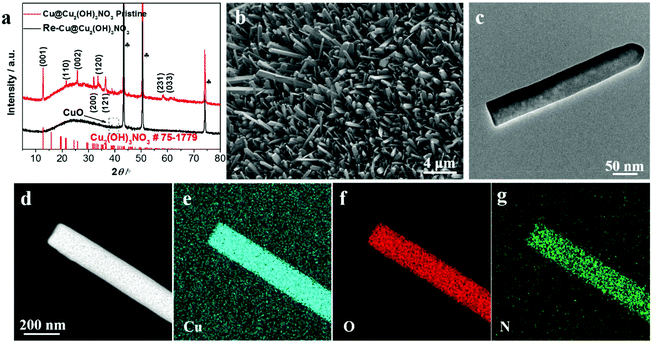
X-ray diffraction (XRD) was employed to analyze the chemical composition of the Cu@Cu2(OH)3NO3 electrode (Fig. 1a). Three strong peaks marked as clubs belong to the Cu mesh.25 The typical peaks emerging at (12.74), (21.6), (25.76), (31.98), (33.64), (36.42), (58.32) and (61.06) can be indexed to the (001), (110), (002), (200), (120), (121), (231) and (033) planes of Cu2(OH)3NO3, respectively (PDF# 75-1779),24,26 indicating the successful fabrication of the Cu@Cu2(OH)3NO3 electrode.The morphology of the Cu@Cu2(OH)3NO3 electrode was investigated by scanning electron microscopy (SEM) and transmission electron microscopy (TEM). The SEM images (Fig. 1b and Fig. S1†) show that the Cu fiber was uniformly covered with the Cu2(OH)3NO3 nanorod. The TEM image (Fig. 1c) further reveals a regular rod-like morphology with a width of about 50 nm. Elemental mapping analysis of the TEM (Fig. 1d–g) and SEM (Fig. S2b–e†) images shows that Cu, O, and N are homogeneously distributed in the nanorod. Energy-dispersive X-ray spectroscopy (EDS, Fig. S2f†) further proves that Cu, O, and N are the principal elemental components, and the atomic ratio of Cu![[thin space (1/6-em)]](https://www.rsc.org/images/entities/char_2009.gif) :
:![[thin space (1/6-em)]](https://www.rsc.org/images/entities/char_2009.gif) O
O![[thin space (1/6-em)]](https://www.rsc.org/images/entities/char_2009.gif) :
:![[thin space (1/6-em)]](https://www.rsc.org/images/entities/char_2009.gif) N = 3.05
N = 3.05![[thin space (1/6-em)]](https://www.rsc.org/images/entities/char_2009.gif) :
:![[thin space (1/6-em)]](https://www.rsc.org/images/entities/char_2009.gif) 8.83
8.83![[thin space (1/6-em)]](https://www.rsc.org/images/entities/char_2009.gif) :
:![[thin space (1/6-em)]](https://www.rsc.org/images/entities/char_2009.gif) 1.59, close to the ratio in the molecular formula (2
1.59, close to the ratio in the molecular formula (2![[thin space (1/6-em)]](https://www.rsc.org/images/entities/char_2009.gif) :
:![[thin space (1/6-em)]](https://www.rsc.org/images/entities/char_2009.gif) 6
6![[thin space (1/6-em)]](https://www.rsc.org/images/entities/char_2009.gif) :
:![[thin space (1/6-em)]](https://www.rsc.org/images/entities/char_2009.gif) 1), further demonstrating the successful preparation of the Cu@Cu2(OH)3NO3 electrode.
1), further demonstrating the successful preparation of the Cu@Cu2(OH)3NO3 electrode.
The elemental composition and chemical states of the pristine Cu@Cu2(OH)3NO3 electrode were investigated by X-ray photoelectron spectroscopy (XPS, Fig. 2). The survey spectrum (Fig. 2a) clearly exhibits the element signals of Cu, O and N, which were consistent with the EDX results. The peaks at 935.35 and 955.21 eV are attributed to Cu2+ 2p3/2 and Cu2+ 2p1/2 in the Cu2(OH)3NO3 layer, respectively (Fig. 2b). The O 1s peak can be deconvoluted into three components: the O–N bond (532.56 eV), the O–H bond (adsorbed oxygen or hydroxide, 532.18 eV), and the O–Cu bond (lattice oxygen, 531.84 eV) (Fig. 2c). The symmetric N 1s peak at 406.91 eV can be assigned to NO3− (Fig. 2d).24,26 The XPS results together with the XRD data strongly indicate the successful preparation of the Cu@Cu2(OH)3NO3 electrode.
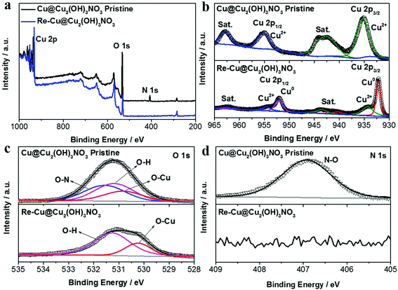 | ||
| Fig. 2 (a) XPS survey spectra and high-resolution XPS spectra of (b) Cu 2p, (c) O 1s, and (d) N 1s of the Cu@Cu2(OH)3NO3 electrode before and after pre-reduction. | ||
CO2 electroreduction performance
The Cu@Cu2(OH)3NO3 electrode was pre-reduced before the electrochemical characterization, and the reduced electrode was labeled as the Re-Cu@Cu2(OH)3NO3 electrode hereafter. Both XRD (Fig. 1a) and XPS data (Fig. 2a–d) reveal that the Cu2(OH)3NO3 nanorod was reduced to metallic Cu,27 but there were some signals of CuO on the surface of the Re-Cu@Cu2(OH)3NO3 electrode, which might be due to oxidation in air.21 TEM and SEM images show that the morphology of the nanorods changed to nanodendrites after pre-reduction (Fig. 3a, b and Fig. S3†), similar to the Cu2(OH)3Cl-derived ERD Cu (electro-redeposition copper), which undergoes dissolution and redeposition of copper from a sol–gel.28 So we hypothesise that our electrode also underwent an electro-redeposition process during the pre-reduction, and NO3− would leach from the rods during this process. Elemental mapping analysis of the SEM image (Fig. 3c–e and Fig. S4b–e†) showed that Cu and O are homogeneously distributed on the surface of the Re-Cu@Cu2(OH)3NO3 electrode, which is consistent with the XRD and XPS data. A trace amount of the N signal might originate from the background or adsorbed contaminant. EDS revealed that the Cu![[thin space (1/6-em)]](https://www.rsc.org/images/entities/char_2009.gif) :
:![[thin space (1/6-em)]](https://www.rsc.org/images/entities/char_2009.gif) O
O![[thin space (1/6-em)]](https://www.rsc.org/images/entities/char_2009.gif) :
:![[thin space (1/6-em)]](https://www.rsc.org/images/entities/char_2009.gif) N ratio was 16.42
N ratio was 16.42![[thin space (1/6-em)]](https://www.rsc.org/images/entities/char_2009.gif) :
:![[thin space (1/6-em)]](https://www.rsc.org/images/entities/char_2009.gif) 1
1![[thin space (1/6-em)]](https://www.rsc.org/images/entities/char_2009.gif) :
:![[thin space (1/6-em)]](https://www.rsc.org/images/entities/char_2009.gif) 0, further excluding the retention of NO3− in the electrode (Fig. S4f†).
0, further excluding the retention of NO3− in the electrode (Fig. S4f†).
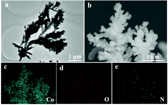 | ||
| Fig. 3 (a) TEM and (b) SEM images and the corresponding elemental mapping images of (c) Cu, (d) O, and (e) N of the Re-Cu@Cu2(OH)3NO3 electrode. | ||
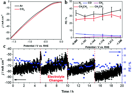
Linear sweep voltammetry (LSV) was first conducted to evaluate the CO2 RR performance on the Re-Cu@Cu2(OH)3NO3 electrode (Fig. 4a). Under Ar purge conditions, the current is mainly ascribed to the hydrogen evolution reaction, the major side reaction during the CO2 reduction reaction. Under CO2 bubbling conditions, an enhanced current density is observed, indicating that the CO2 reduction reaction occurs readily on the Re-Cu@Cu2(OH)3NO3 electrode. A similar trend also appears in the Cu mesh electrode, which acts as a control sample (Fig. S5†).
It is well known that the selectivity of CO2 RR is dependent on the applied potential.29 Therefore, the chronoamperometry (CA) experiments were performed at different potentials to measure the FEs of different products. The total FE of all detectable products amounts to 87.64–95.48%, which indicates that the system was well calibrated (Fig. S6 and 7†). The product distribution trend exhibited by the bare Cu mesh electrode is consistent with previous studies29,30 (Fig. S6 and Table S1†), where CH4 dominates the carbonaceous products with a highest FE of 49.68%. In contrast, the highest FE for C2H4 is only 15.77%. When CO2 reduction is performed on the Re-Cu@Cu2(OH)3NO3 electrode (Fig. 4b, Fig. S7 and Table S2†), CH4 production dramatically decreases with a FE less than 2%. This may result from the high local pH value on the surface of the electrode where the protonation of CO and methane formation were suppressed.13 As a result, the FE of C2H4 is improved to 31.80%. It is interesting to observe that the increase of the FE of C2H4 is accompanied by the decrease of CO. In other words, C2H4 was produced primarily at the expense of CO evolution. This behavior is consistent with previous reports where CO is the intermediate in the formation of C2+ products.17,23,28 It should be noted that the FE of H2 increased compared with the Cu mesh electrode, which may be the result of the enhanced adsorption of hydrogen (*H) on the surface of the electrode.31 Formate is the primary liquid product under all potentials with a highest FE of 18.20%.
To evaluate the stability of the Re-Cu@Cu2(OH)3NO3 electrode, electrolysis at a fixed potential (−1.213 V vs. RHE) was carried out (Fig. 4c). The FE of C2H4 remained around 30% over 20 h with three time intervals. During each time interval, the current density decreased from 80 mA cm−2 to 60 mA cm−2 gradually. This phenomenon reemerges when fresh electrolyte was added, which indicates that it is due to the vaporization of the catholyte rather than the deactivation of the electrode. This result demonstrates that the Re-Cu@Cu2(OH)3NO3 electrode possesses excellent stability.
Discussion
Compared with the bare Cu mesh electrode, the Re-Cu@Cu2(OH)3NO3 electrode showed an almost complete suppression of CH4 formation with an improved C2H4 formation. We attribute the enhanced selectivity of C2H4 to two main reasons: high local pH and defects.On the one hand, Cu2(OH)3NO3 was reduced to metallic Cu, leaving a dendritic rough surface after pre-reduction. These dense nanodendrites increase the surface roughness, leading to the mass diffusion limitations and further cause a high local pH value at the electrode and electrolyte interface. Because the CH4 formation is pH dependent and the C2H4 formation is pH independent, finally the CH4 formation is suppressed while the C2H4 formation is enhanced.13
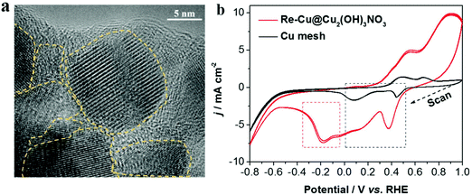
On the other hand, during the pre-reduction process, there are abundant grain boundaries and defects with low-coordinated Cu atoms formed on the electrode. The defect sites on Cu-based electrocatalysts are important for reducing CO2 to C2+ compounds, because they could adsorb the intermediate (CO) stronger, benefiting the subsequent deep reduction and the formation of C2+ products.20,21 Here, three methods were used to identify the defect sites. First, HRTEM (high-resolution TEM) images (Fig. 5a and Fig. S8†) clearly show abundant grain boundaries (one kind of defect) exposed on the surface of Cu2(OH)3NO3-derived Cu. The second one is the voltammetry signatures as shown in the cyclic voltammograms of the Re-Cu@Cu2(OH)3NO3 electrode and the bare Cu mesh electrode (Fig. 5b and Fig. S9†). Both electrodes exhibited two major reduction peaks in the potential range of 0–0.5 V (vs. RHE, marked in the black frame), which can be assigned to the reduction peaks of Cu2+/Cu+ and Cu+/Cu0 couples,32 respectively. Interestingly, a reduction peak at ∼−0.18 V was identified on the Re-Cu@Cu2(OH)3NO3 electrode only (marked in the red frame). This peak is assigned to the reduction of Cu defect sites according to the previous literature.33,34 The peak is detectable after 20 h of continuous electrolysis (marked in the red frame), also demonstrating that the defects are stable during the long-term CO2 reduction experiment (Fig. S10†). Third, it has been reported that the surface defects (vacancy) can be evaluated by the ratio between the XPS peaks of adsorbed oxygen (Oads) and lattice oxygen (Olatt), and the higher ratio indicates a larger amount of surface oxygen vacancies.20 Thus, we carefully calculated the ratios before and after the pre-reduction. The ratio of adsorbed oxygen (Oads) to lattice oxygen (Olatt) after pre-reduction is 2.94, nearly twice the ratio before pre-reduction (1.59, Table S3†), though there is a huge amount of hydroxide (OH−) in the Cu2(OH)3NO3 crystal. This indicates that the Re-Cu@Cu2(OH)3NO3 electrode possesses a high density of defect sites on the surface.
Possible reaction pathway
Based on the previous literature,21,35 the possible reaction pathway of the enhanced selectivity to C2H4 on the Re-Cu@Cu2(OH)3NO3 electrode is proposed, Fig. 6. The first step involves electron and proton transfer to form a *COOH intermediate, which is hydrogenated to give moderately adsorbed *CO on the defect-rich surface. Then *CO might proceed through three different paths to form the C2HxO2 intermediate, which will be finally reduced to produce C2H4. Path I involves the C–C coupling between two *CO intermediates. Path II involves the hydrogenation of *CO to *CHO/*COH, followed by C–C coupling between *CO and *CHO/*COH. Path III involves the C–C coupling between *CHO/*COH and *CHO/*COH. Due to the high local pH caused by the rough dendritic surface, the protonation of CO into CH4 is suppressed. Meanwhile, the defect-rich surface could chemisorb and stabilize the intermediates, finally resulting in an enhanced selectivity for C2H4.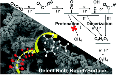 | ||
| Fig. 6 Proposed pathway for the electroreduction of CO2 to ethylene on the Re-Cu@Cu2(OH)3NO3 electrode. | ||
Conclusion
In summary, a facile molten salt decomposition method was employed to prepare the Cu@Cu2(OH)3NO3 electrode for electrochemical CO2 reduction. The Cu2(OH)3NO3 nanocrystal on the surface of the electrode was converted into metallic Cu after pre-reduction, leaving abundant defects on the dendritic rough surface, which were identified by HRTEM, electrochemical method and XPS. Benefiting from the high density of defects and the high local pH, the Re-Cu@Cu2(OH)3NO3 electrode exhibited a high selectivity for C2H4 production with a FE of 31.80% and a high stability for more than 20 h. This work opens up exciting new avenues to explore Cu-based electrodes for electrochemical carbon dioxide reduction.Conflicts of interest
There are no conflicts to declare.Acknowledgements
J. L. acknowledges the funding support from the Fundamental Research Funds for the Central Universities, Nankai University (63201178) and the Overseas Expertise Introduction Project for Discipline Innovation of Higher Education of China (Grant No. B16027).References
- L. Zhang, Z. Zhao and J. Gong, Angew. Chem., Int. Ed., 2017, 56, 11326–11417 CrossRef CAS PubMed.
- T. Hoang, S. Verma, S. Ma, T. Fister, J. Timoshenko, A. Frenkel, P. Kenis and A. A. Gewirth, J. Am. Chem. Soc., 2018, 140(17), 5791–5797 CrossRef CAS PubMed.
- M. Schreier, F. Héroguel, L. Steier, S. Ahmad, J. Luterbacher, M. Mayer, J. Luo and M. Grätzel, Nat. Energy, 2017, 2, 17087–17096 CrossRef CAS.
- J. Gao, H. Zhang, X. Guo, J. Luo, S. Zakeeruddin, D. Ren and M. Grätzel, J. Am. Chem. Soc., 2019, 141(47), 18704–18714 CrossRef CAS PubMed.
- C. Dinh, T. Burdyny, M. Kibria, A. Seifitokaldani, C. Gabardo, F. Arquer, A. Kiani, J. Edwards, P. Luna, O. Bushuyev, C. Zou, R. Bermudez, Y. Pang, D. Sinton and E. Sargent, Science, 2018, 360, 783–787 CrossRef CAS PubMed.
- S. Nitopi, E. Bertheussen, S. Scott, X. Liu, A. Engstfeld, S. Horch, B. Seger, I. Stephens, K. Chan, C. Hahn, J. Nørskov, T. Jaramillo and Ib Chorkendorff, Chem. Rev., 2019, 119, 7610–7672 CrossRef CAS PubMed.
- G. Britovsek, M. Bruce, V. Gibson, B. Kimberley, P. Maddox, S. Mastroianni, S. McTavish, C. Redshaw, G. Solan, S. Strömberg, A. White and D. Williams, J. Am. Chem. Soc., 1999, 121, 8728–8740 CrossRef CAS.
- Y. Zhang, V. Sethuraman, R. Michalsky and A. Peterson, ACS Catal., 2014, 4, 3742–3748 CrossRef CAS.
- Y. Gao, Q. Wu, X. Liang, Z. Wang, Z. Zheng, P. Wang, Y. Liu, Y. Dai, M. Whangbo and B. Huang, Adv. Sci., 2020, 1902820–1902827 CrossRef CAS PubMed.
- M. Ma, K. Djanashvili and W. Smith, Angew. Chem., Int. Ed., 2016, 55, 6680–6684 CrossRef CAS PubMed.
- C. W. Li and M. W. Kanan, J. Am. Chem. Soc., 2012, 134, 7231–7234 CrossRef CAS PubMed.
- K. Jiang, R. Sandberg, A. Akey, X. Liu, D. Bell, J. Nørskov, K. Chan and H. Wang, Nat. Catal., 2018, 1, 111–119 CrossRef CAS.
- H. Mistry, A. Varela, C. Bonifacio, I. Zegkinoglou, I. Sinev, Y. Choi, K. Kisslinger, E. Stach, J. Yang, P. Strasser and B. Cuenya, Nat. Commun., 2016, 7, 12123–12130 CrossRef PubMed.
- Z. Liang, T. Zhuang, A. Seifitokaldani, J. Li, C. Huang, C. Tan, Y. Li, P. Luna, C. Dinh, Y. Hu, Q. Xiao, P. Hsieh, Y. Wang, F. Li, R. Bermudez, Y. Zhou, P. Chen, Y. Pang, S. Lo, L. Chen, H. Tan, Z. Xu, S. Zhao, D. Sinton and E. Sargent, Nat. Commun., 2018, 9, 3828–3836 CrossRef PubMed.
- D. Gao, I. Sinev, F. Scholten, R. Arán-Ais, N. Divins, K. Kvashnina, J. Timoshenko and B. Cuenya, Angew. Chem., Int. Ed., 2019, 58, 2–9 CrossRef.
- Y. Hori, I. Takahashi, O. Koga and N. Hoshi, J. Phys. Chem. B, 2002, 106, 15–17 CrossRef CAS.
- F. Li, A. Thevenon, A. Rosas-Hernández, Z. Wang, Y. Li, C. Gabardo, A. Ozden, C. Dinh, J. Li, Y. Wang, J. Edwards, Y. Xu, C. McCallum, L. Tao, Z. Liang, M. Luo, X. Wang, H. Li, C. O'Brien, C. Tan, D. Nam, R. Bermudez, T. Zhuang, Y. Li, Z. Han, R. Britt, D. Sinton, T. Agapie, J. Peters and E. Sargent, Science, 2020, 577, 509–513 CAS.
- T. Hoang, S. Ma, J. Gold, P. Kenis and A. Gewirth, ACS Catal., 2017, 7, 3313–3321 CrossRef CAS.
- Z. Geng, X. Kong, W. Chen, H. Su, Y. Liu, F. Cai, G. Wang and J. Zeng, Angew. Chem., Int. Ed., 2018, 57, 6054–6059 CrossRef CAS PubMed.
- Z. Gu, N. Yang, P. Han, M. Kuang, B. Mei, Z. Jiang, J. Zhong, L. Li and G. Zheng, Small Methods, 2018, 1800449–1800457 CrossRef.
- D. Ren, Y. Deng, A. Handoko, C. Chen, S. Malkhandi and B. Yeo, ACS Catal., 2015, 5, 2814–2821 CrossRef CAS.
- Y. Chen, C. W. Li and M. W. Kanan, J. Am. Chem. Soc., 2012, 134, 19969–19972 CrossRef CAS PubMed.
- H. Wang, Z. Liang, M. Tang, G. Chen, Y. Li, W. Chen, D. Lin, Z. Zhang, G. Zhou, J. Li, Z. Lu, K. Chan, T. Tan and Y. Cui, Joule, 2019, 3, 1–10 CrossRef.
- Y. Ma, J. Chu, Z. Li, D. Rakov, X. Han, Y. Du, B. Song and P. Xu, Small, 2018, 14, 1803783–1803790 CrossRef PubMed.
- M. Ma, K. Djanashvili and W. A. Smith, Angew. Chem., Int. Ed., 2016, 55, 6680–6684 CrossRef CAS PubMed.
- L. Di, D. Duan, Z. Zhan and X. Zhang, Adv. Mater., 2016, 1600760–1600765 Search PubMed.
- D. Ren, J. Gao, L. Pan, Z. Wang, J. Luo, S. Zakeeruddina, A. Hagfeldt and M. Grätzel, Angew. Chem., 2019, 131, 15178–15182 CrossRef.
- P. Luna, R. Q. Bermudez, C. T. Dinh, M. B. Ross, O. S. Bushuyev, P. Todorović, T. Regier, S. O. Kelley, P. Yang and E. H. Sargent, Nat. Catal., 2018, 1, 103–110 CrossRef.
- D. Ren, J. Fong and B. S. Yeo, Nat. Commun., 2018, 9, 925–933 CrossRef PubMed.
- K. Manthiram, B. J. Beberwyck and A. P. Alivisatos, J. Am. Chem. Soc., 2014, 136, 13319–13325 CrossRef CAS PubMed.
- M. Luo, Z. Wang, Y. C. Li, J. Li, F. Li, Y. Lum, D. Nam, B. Chen, J. Wicks, A. Xu, T. Zhuang, W. Leow, X. Wang, C. Dinh, Y. Wang, Y. Wang, D. Sinton and E. Sargent, Nat. Commun., 2019, 10, 5814–5821 CrossRef CAS PubMed.
- W. Tang, A. Peterson, A. Varela, Z. Jovanov, L. Bech, W. Durand, S. Dahl, J. Nørskov and Ib Chorkendorff, Phys. Chem. Chem. Phys., 2012, 14, 76–81 RSC.
- D. Ren, N. Wong, A. Handoko, Y. Huang and B. S. Yeo, J. Phys. Chem. Lett., 2016, 7, 20–24 CrossRef CAS PubMed.
- H. Jeon, S. Kunze, F. Scholten and B. Cuenya, ACS Catal., 2018, 8, 531–535 CrossRef CAS.
- W. Ma, S. Xie, T. Liu, Q. Liu, Q. Fan, J. Ye, F. Sun, Z. Jiang, Q. Zhang, J. Cheng and Y. Wang, Nat. Catal., 2020, 3, 478–487 CrossRef CAS.
Footnote |
| † Electronic supplementary information (ESI) available. See DOI: 10.1039/d0nr02591g |
| This journal is © The Royal Society of Chemistry 2020 |

