Recent advances in the synthesis and application of photocatalytic metal–metal oxide core–shell nanoparticles for environmental remediation and their recycling process
Kunal Mondal*a and
Ashutosh Sharma*b
aDepartment of Chemical and Biomolecular Engineering, North Carolina State University, 911 Partners Way, Raleigh, North Carolina 27695, USA. E-mail: kmondal@ncsu.edu
bDepartment of Chemical Engineering, Indian Institute of Technology Kanpur, Kanpur-208016, Uttar Pradesh, India. E-mail: ashutos@iitk.ac.in
First published on 25th August 2016
Abstract
Core–shell nanoparticles are a special category of materials with nanostructures that have obtained more attention in recent times owing to their fascinating properties and extensive choice of applications in catalysis, photocatalysis, materials chemistry, biology, drug delivery, sensors and other electronic device applications. By wisely modifying the cores along with the shells material and morphology, a variety of core–shell nanostructures can be created with tunable properties that can perform vital roles in several catalytic and photocatalytic developments and promise sustainable solutions to current environmental remediation problems. Recently, the development of core–shell nanoparticles with Au, Ag, Pt, Pd, Zn, Ni etc. metals as a core and ZnO, TiO2, SiO2, Cu2O, Fe2O3 and SnO2 etc. metal oxide semiconductors as a shell has engrossed huge research interest in catalysis, photocatalysis, solar photovoltaics and so on owing to their tunable nanoscale functionalities in the core and shell particles. This review covers the core–shell nanomaterials, mainly, metal–metal oxide core–shell nanostructures with an overview of the recent advances in their synthesis, and applications. It includes a critical review of application of these materials towards photocatalytic wastewater purification and bacterial disinfections under UV and visible light irritation. It also includes a brief discussion on mechanisms of heterogeneous and homogeneous photocatalysis and the effect of different morphologies of photocatalysts in view of photocatalysis for wastewater treatment. Finally, recycling, reuse and actual photocatalysis in a photocatalytic reactor of core–shell nanostructures have also been discussed which is very important for a sustainable wastewater treatment. The future prospects of such core–shell nanoparticles for cancer treatment by hyperthermia, drug delivery and several other interesting applications have been covered with a distinct emphasis on their structural depending properties.
1. Introduction
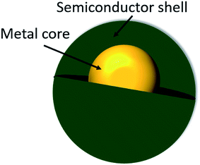
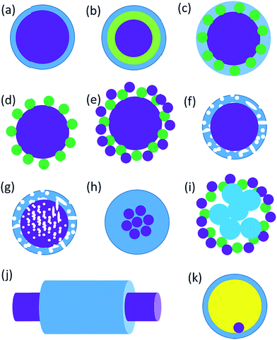
Core–shell nanostructured materials have developed significant research interest for the last couple of decades owing to their impending uses in several fields such as heterogeneous photocatalysis, energy storage, biosensing, gas sensing, biomedical and electronic and bioelectronics applications, and many others.1–12 Interestingly, a recent investigation shows that around one thousand reports have been published per year on core/shell nanoparticles mentioning their synthesis and applications.13 The core–shell nanostructured materials can be fabricated with diverse shapes and sizes of varying core as well as shell widths by means of different structural morphologies. These nanoparticles could be of any shape like centric, eccentric, spherical, star-shaped, fibrous or tubular and so on.14 The physicochemical properties of the core–shell nanostructures may be modified simply by adjusting their size and shape focusing on their particular applications.1,14–16 Different core–shell nanostructures have many distinct characteristics which have been used in various fields of biomedical and nanomedicine, like drug delivery,17 bioimaging,18 cancer treatment,19 so on and so forth.20 Recently, core–shell nanoparticles are engineered with solid core and porous shell such as porous metal–silica, metal–zeolite etc., have been progressively used for extremely capable separation with reasonably low back pressure and quick flow rate.21 The macroscopic solid core and shell offers low working back pressure whereas the nanoporous shell and small solid core can deliver very higher surface area for the separation to happen. When the surface morphology of the nanoparticles is altered by means of coating with a thin film of other materials, adding various chemical functional groups or even attaching other molecules they display better material characteristics than the uncoated nonfunctionalized nanoparticles. Interestingly, there are various kinds of core–shell nanostructures are possible, such as metal-core and semiconductor shell, metal-core and nonmetal shell, metal-core and different metal shell, semiconductor-core and metal shell, semiconductor core and dissimilar semiconductor shell, metal-core and polymer shell, nonmetal-core and nonmetal shell, semiconductor-core and polymeric shell, polymeric-core and nonmetallic shell and core and shell of two dissimilar polymers. Intended for these types of nanostructures, the material of the core and the shell may be interchanged. There is a schematic illustration of a metal-core and semiconductor-shell nanoparticles which is shown in Fig. 1.The design and production of innovative core–shell nanostructured nanomaterials with metals, polymers, semiconductors, alloys, graphene, carbon nanotubes, and quantum dots etc. that own extraordinary functionalities are one of the key challenges in core–shell nanoparticle research.22–28 In a typical core–shell morphology, the core and the shell can be formed by different materials or the identical materials but with dissimilar structures.1,29–32 Fig. 2 shows the schematic depiction of different kinds of core/shell nanoparticle morphologies where the core and the shell are conveyed in different colors. It was observed that sometimes the core may be a single sphere (Fig. 2a) or aggregation of many continuous shells (Fig. 2b). It is also possible that the shell is continuous and incorporated several small spheres within it (Fig. 2c). Complex core–shell assemblies may also be made where the shell may be made of either many small identical spherical particles or different spheres shown in Fig. 2d and e, respectively. The shell structure can be a porous layer (Fig. 2f) when core is nonporous solid or both the core and the shell can be porous (Fig. 2g). It is also found that the core is in the form of multiple small sphere which are covered by a continuous single shell (Fig. 2h) or a shell layer with several spherical particles (Fig. 2i). Interestingly, the core–shell morphology cab be made in the form of solid fibers as shown in Fig. 2j. Also, the core–shell structure can form yolk–shell structure where there is a movable core situated inside a hollow shell (Fig. 2k).33 The selection of morphology of core–shell particles depends on specific application, for example, the core–shell particles employed in chromatography are generally made of the similar material, commonly SiO2, however, with a porous shell and solid core. The size of the core particle, the thickness of the shell material and the porosity in the core or shell are adjusted to garb different kinds of applications. In case of photocatalytic application, the porous semiconducting shell and conducting core particles are preferred.
In this context, the metal and metal oxide semiconductor, polymer core–shell have engrossed substantial curiosity as a class of innovative nanomaterials with interesting uses in numerous electronics containing organic photovoltaics solar cells, sensors, organic light-emitting diodes, and field effect transistors etc. owing to their benefits, such as cheap price and stress-free device fabrication capabilities.13,34–37
The core–shell nanoparticles are designed by numerous fabrication methods like sol–gel process, hydrothermal production, emulsion polymerization technique, microemulsion polymerization, solvothermal synthesis, and chemical vapor deposition method etc.38–44 These particles are typically fabricated by a dual-step or many-step synthesis route. Firstly, the core is made and then shell is formed on the core particle through various techniques subjected to the variety of core–shell nanostructured materials and their surface morphologies.45 Interestingly, the core–shell nanostructured nanoparticles have been mostly explored, as compared to core–shell microspheres.
Recently, copious research consideration has been dedicated to metal–semiconductor core–shell particles created on silver, gold, platinum, and palladium etc., core and titanium dioxide, silica, zirconia, zinc oxide etc., shell since their nanoscale properties which distinctly vary from their bulk counterparts.2,46–48 These nanoparticles of metal–semiconductor core–shell morphologies exhibit size-reliant quantum-size effects49 and can be utilized for a variety of applications requiring advanced functionality such as sensors, energy storage, electronics, optoelectronics, catalysis and photocatalysis.50 The catalytic and plasmonic characteristics of the novel metals and the photocatalytic properties of the semiconductors open up a new area of application for these metal–semiconductor core–shell nanoparticles as a promising photocatalyst material.51–53 The metal–semiconductor core–shell nanostructured photocatalysts can modify greatly semiconductor energy band diagram, lower the bad gap energy and causing a slow electron–hole pair recombination rate with a fast electron transfer ability.54 Thus, these core–shell photocatalysts with metal–semiconductor nanoparticles can perform efficient visible light photocatalyst and find interesting applications in the field of air and wastewater purification, bacterial disinfections and so on. Therefore, the motivation in the exploration of core–shell nanoparticles is to associate the chosen belongings of dissimilar materials and nanostructures in order to provide synergistic result, to stabilize the active nanoparticles, or to deliver biocompatibility into the functional matrix and explore various applications accordingly.
In this review we have discussed the challenges and recent advancement in the synthesis of metal–semiconductor core–shell nanostructures and their application prospects utilizing their interesting structures and catalytic and electronic properties. Also the photocatalytic reaction mechanisms for the core–shell nanostructures and their potential applications for environmental remediation, in particular-towards waste treatment by organic pollutant removal and bacterial disinfection from wastewater, air purification by UV and visible light mediated photocatalysis.
2. Mechanisms of photocatalysis
The energy difference between the valence band (VB) and the conduction band (CB) of the semiconductor is acknowledged as the ‘Band Gap’. When TiO2, ZnO, ZrO2, and CdSe etc., photocatalyst semiconductor absorbs ultraviolet energy from sunlight or any irradiated artificial light source (fluorescent lamps, light emitting diodes etc.), it yields an electron–hole pair only if the energy is more than the bandgap energy of the material. The conduction band electron (eCB−) of the photocatalyst gets excited because of the exposure of the illuminated light energy. This phase is said as the photocatalyst's ‘photo-excitation’ state. The photo generated electron is negative and the hole is positively charged. The positively charged hole of the photocatalysts in valance band (hVB+) splits the water molecule into hydrogen gas and high energetic hydroxyl free radical. The electron counters with oxygen and produces super oxide anion. This cycle lasts until the light energy is accessible.The photocatalysis process and the related chemical reactions are elucidated as follows with the help of eqn (i)–(ix). The reaction mechanism for ZnO and TiO2 photocatalysts are explained by Sharma's group.55,56 By way of the semiconductor photocatalyst exposed with illuminated light, the valence band electron goes to the conduction band creating a positively charged hole in the valance band. The photocatalysts would be further efficient if these and hVB+ will spend longer time prior to recombine. The eCB− electrons counter with oxygen and H+ of the aqueous medium and produce H2O2 which further originated into OH− ion and OH˙ free radical. Likewise, hVB+ respond with H2O to contribute OH˙ free radical. Creation of these highly energetic reactive species supports to reduce the recombination rate of electron–hole pair and provides additional time for dealings with the organic pollutant molecules. Fig. 3 shows idea of the photocatalysis thorough a pictorial illustration.
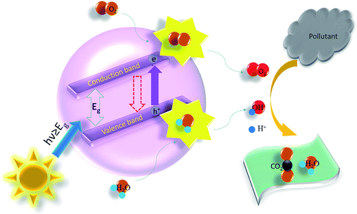 | ||
| Fig. 3 The idea of degradation of pollutant by heterogeneous photocatalysis. Here, the redox potentials (E0) of some active radicals, such as H+/H2, O2/O2− and H2O/OH− should be noted as 0 V, −0.33 V and −0.42 V, respectively.57 | ||
The mechanisms of two other situations (a) the CB of photocatalyst is less negative than the O2/O2− redox potential and (b) the VB of photocatalyst is less positive than the H2O/OH− redox potential. To achieve overall wastewater treatment, the energy necessities indicate that the bottom of the CB must be located at a more negative potential than the reduction potential of H+/H2 (0 V vs. NHE at pH 0), whereas the top of the VB essentially be located more positively than the oxidation potential of H2O/O2 (1.23 V vs. NHE). Conferring to this theoretical value, the photocatalysis can only be directed if the photon energy is greater than 1.23 eV. This amount energy is equal to the energy of a photon (wavelength of ∼1010 nm), signifying that visible light holds enough energy for the degradation of wastewater in aqueous medium.
The photocatalytic oxidation of organic compounds under UV light can be presented as follows:56
| Semiconductor photocatalyst + hν → eCB− + hVB+ | (i) |
| h+ + H2O → H+ + OH˙ | (ii) |
| h+ + OH− → OH˙ | (iii) |
| e− + O2 → O2− | (iv) |
| 2e− + O2 + 2H+ → H2O2 | (v) |
| e− + H2O2 → OH˙ + OH− | (vi) |
| Organic pollutant + OH˙ → degradation products | (vii) |
| Organic pollutant + semiconductor photocatalyst (hVB+) → oxidation products | (viii) |
| Organic pollutant + semiconductor photocatalyst (eCB−) → reduction products | (ix) |
The recombination of the excited electron–hole pair produces excess energy from the excitation of the electron which releases in the form of heat. As the recombination process is unwanted and causes to an incompetent photocatalysis, therefore the crucial aim of the photocatalysis is to achieve a catalytic reaction among the excited eCB− electrons and oxidant to harvest a reduced product. Furthermore, a reaction among the generated with a reductant is a must desirable to yield an oxidized product. It is important to mention that the reduction and oxidation reactions occur at the surface of photocatalysts since this reaction creates positive holes and electrons. In the oxidative reaction, the positive hVB+ counter with the moisture content on the catalyst surface and yield a hydroxyl free radical. In addition, if more oxygen is supplied from outside to the photocatalytic reactor, this will perform as electron acceptors and can boost the degradation of pollutant by further delaying the recombination rate.55 Also, the total time for the complete pollutant degradation increases with the reduction in photocatalyst loading. Fig. 4 depicts a typical photocatalytic degradation of a PAH pollutant naphthalene in wastewater where it describes the gradual degradation of the pollutant by measuring its absorption with time.
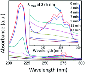 | ||
| Fig. 4 Monitoring of a typical photocatalysis by UV-vis absorption spectrophotometer. Here, a typical aqueous naphthalene solution was mixed with TiO2-NF and data collected at different time interval. The inset image shows magnified λmax (monitored at 275 nm wavelength). Reprinted with permission from ref. 56. Copyright (2014) American Chemical Society.56 | ||
2.1 Heterogeneous photocatalysis
Heterogeneous photocatalysis is a well-developed branch of chemical catalysis appreciated for wastewater treatment and air purification. In case of heterogeneous catalysis, the phase of the catalyst is different from the reactants. Heterogeneous photocatalysis contains a large variety of reactions, such as dehydrogenation, minor or total oxidations, hydrogen transfer, water detoxification, metal deposition, deuterium–alkane isotopic exchange, gaseous and aqueous pollutant removal, etc. The utmost common examples of heterogeneous photocatalyst are the transition metal oxides and semiconductors, which have exceptional features.2.2 Homogeneous photocatalysis
In a homogeneous photocatalytic reaction, the reactants and the photocatalysts are exist in the similar phase. The ozonolysis and photo-Fenton systems are the most commonly employed homogeneous photocatalysts. Fenton revealed that a combination of hydrogen peroxide and Fe(II) in acidic environment have very dominant oxidizing properties.58 However, the exact mechanism of this reaction, now identified as the Fenton reaction, is still the topic of some debate.59,60 It is usually presumed to be an imperative chemical source of hydroxyl radicals. The classical mechanism can be demonstrated as a simple redox reaction in which Fe(II) is being oxidized to Fe(III) and H2O2 and further reduced to hydroxide ion and the hydroxyl radical.Here in this catalysis the reactive species ˙OH is employed for diverse commitments. The hydroxyl radical production mechanism of by ozone can occur in the following paths.61
| O3 + hν → O2 + [O] | (x) |
| [O] + H2O → H2O2 | (xi) |
| H2O2 + hν → ˙OH + ˙OH | (xii) |
| [O] + H2O → ˙OH + ˙OH | (xiii) |
In the same way, the Fenton system yields hydroxyl radicals by the following way:62
| Fe2+ + H2O2 → ˙OH + Fe3+ + OH− | (xiv) |
| Fe3+ + H2O2 → Fe2+ + ˙OOH + H+ | (xv) |
| Fe2+ + ˙OH → Fe3+ + OH− | (xvi) |
In a photo-Fenton kind reaction processes, additional sources of ˙OH generated over photocatalysis of hydrogen peroxide, and reduction of Fe3+ ions in presence of light energy:63
| H2O2 + hν → 2HO˙ | (xvii) |
| Fe3+ + H2O + hν → Fe2+ + H+ + ˙OH | (xviii) |
The productivity of the photon-Fenton kind routes is governed to some operational parameters such as pH of the solution, concentration of H2O2, and intensity of UV light. The key benefit of this reaction is the capability of expending solar energy spectrum up to 470 nm, and can escaping the use of high priced UV and electrical energy sources. The photon-Fenton processes have been recognized much competent than the other photocatalytic reactions. In spite of that, the main drawbacks of these process are the low operating pH standards which are necessary for the reactions, since iron precipitates at higher pH.
3. Effect of photocatalyst morphology on photocatalysis
The photocatalytic oxidation process be influenced by creation and recombination of electron–hole pair within the photocatalyst. The oxygen molecules absorbed on the surface of the semiconductor photocatalyst performs as an electron imprisoner and can govern the photo induced electron–hole pair recombination process. The nanostructured semiconductor owns superior photocatalytic competence as compared to the bulk photocatalysts.64,65 The causes behind this can be explained by quantum size effect and higher specific surface area.The size of the catalyst particles when turn out to be less than a certain precarious limit (i.e., size decreases to the nanometer size range) this causes quantum size effects owing to the confine movement of electrons. The quantum size effect is one of the utmost direct effects and this can leads to the conduction band and valence band of the semiconductor catalyst to change into discretized energy states. This discretization process depends on the size of the material structure, which indicates that either the potential of valence band alters more positively, or the conduction band potential becomes further negative. Thus, the red-ox potential of the electrons and holes is augmented, and thereby the oxidation reactivity of nanostructured photocatalysts is improved.66,67
The other important factor is the higher specific surface area of the catalysts. The adsorption capacity of the semiconductor photocatalysts to organic waste materials increased if there are additional atoms be present onto the surface. The photocatalytic activity of the catalyst is related to the time period drained by electron–hole pairs to get in contract to the particles surface. When the sizes of the particle are in nano-regime the diameter of those catalysts becomes very minute, then the movement of the charge carriers from inside to the surface becomes very straightforward, and so benefits to red-ox reaction. Greater the surface area to volume ratio, lesser the diameter of the particle and the shorter time may be taken up by electron–hole pairs diffusing to the surface from inside of the catalyst. This can deliver reduced probability for the recombination of electron and hole. Consequently, the more photocatalytic action can be attained. Therefore, the nanosized semiconductors have superior photocatalytic proficiency than the bulk.68,69
The catalytic activity greatly influenced by porous nature and porosity distribution of the photocatalyst. The optimum porosity distribution in a micro (pore size < 2 nm)/mesoporous (pore size ∼ 2–50 nm) catalyst is essential for efficient catalysis. Auyeung et al.70 demonstrated the method for controlling structure and porosity in catalytic nanoparticles. In case of heterogeneous catalyst with an enforced nanotexture, such as zeolite, mesoporous sieve etc. the distribution of macropores and large mesopores helps if efficient transportation reactants to overcome diffusion limitations during catalytic reaction. The pore size and porosity distribution are of great significance to the practical use of sensibly designed nanoporous catalysts, as the absence of an elegant porous interconnected network assembly at greater length scales might unfavorably affect the overall photocatalytic performance. Interestingly, the presence of big pores in channels ease access to the active catalytic sites, however, it diminishes the quantity of active catalysts. Thus, there is a clear need of an optimally distributed porosity. In this context, Coppens group demonstrated that the catalysts usually get benefit from a hierarchically porous network with an extensive pore-size distribution.71
3.1 Nanostructured metal-oxide semiconductor photocatalysts
A nanostructured semiconductor photocatalyst is a class of semiconducting nanomaterials that produces catalytic activity by means of light energy. Semiconductor metal-oxides nanostructured photocatalysts have attained excessive technological significance in electronics and environmental remediation. The encouraging electronic structural arrangement, superior light absorption abilities, and favorable charge transport properties of the metal-oxide nanomaterials has made conceivable its use as photocatalyst.55The noteworthy features of the photocatalysts are the appropriate band gap, preferred morphology, high surface area to volume ratio, chemical and thermal stability and most important the reusability.72–75 Titanium dioxide, zinc oxide, zirconium dioxide, cadmium selenide are the typical photocatalyst materials. Other metal-oxides like oxides of vanadium, tin, cerium and chromium, possessing these features show comparable photocatalysis and are able to oxidize organic pollutant molecules to degrade completely or else convert them to less hazardous derivatives.
There are many nanomorphologies of photocatalysts such as nanoparticles, thin films, nanospheres, nanofibers, nanotubes, nanoribbons and core–shell nanostructured photocatalysts described in the literature for their exciting photocatalytic activities. Among those nanostructures core–shell nanostructured photocatalysts are the most efficient one.
There are lot of semiconductor metal-oxides nanostructures plentifully available in nature such as ZnO, SnO2, TiO2, and CeO2, BiVO4, Bi2WO6, InTaO4, Zn1.7GeN1.8O, ZnAl2O4, ZnGaNO and so on which have also been extensively used as photocatalysis, predominantly as heterogeneous photocatalysis application since quite a few decades. Metal-oxides nanostructured semiconductors are very useful in chemical catalysis due to their excellent chemical stability in a diverse environmental conditions, biocompatibility, and competence to create electron–hole pair when irradiated with necessary expanse of photon energy owing to their nanoscopic properties.
3.2 Nanotube
There is an ongoing research exertion to exploit the distinctive structures of these nanoscale photocatalysts by altering parameters such as shape, size, and arrangement of patterns. One-dimensional (1D) nanostructured morphologies such as nanotubes, nanorods, and nanofibers, have turn out to be a hot research topic in the area of photocatalysis due to their exceptional physicochemical belongings and anisotropic configurations.77–79 Efforts have been made on various processes parameters to obtained different shaped nanostructures and among these, tubular and rod shaped structures are much explored. The photocatalyst with nanotubes have structurally stable to several hundred degree Celsius temperature. The nano interface, wall thickness, and tube-to-tube interaction points seem to have important roles in defining the photocatalytic performance.80 In the recent past, Kang et al.81 have synthesized nanotube nanostructures of titanium dioxide photocatalyst and demonstrated towards the photocatalytic reduction of methylene blue. They have observed that within the slight temperature range, the titania nanotube arrays showed a binary combination of brookite and anatase crystalline phases which are highly effective for photolysis. Grimes's group has fabricated tapered, conical-shaped TiO2 nanotubes expending anodic oxidation process.80 Interestingly, Ratanatawanate et al.82 have been synthesized S-nitrosocysteine ornamented PbS quantum dots/TiO2 nanotubes for better creation of singlet O2 where they have used the nanomorphology as a nitric oxide releasing vehicle to promote photocatalysis. In a recent study Gupta and his co-workers have been developed extreme-dense ZnO nano-forest comprising of vertically grown high aspect ratio nanotube/nanorod like nanostructures and demonstrated their prospective as photocatalysts.76 Interestingly, Fig. 5 shows the typical FESEM images of 1D zinc oxide nanotube/nanorod nanomorphologies pinned in nanocarpets which was reported by Gupta et al.76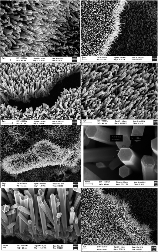 | ||
| Fig. 5 FESEM micrographs of ZnO nanoforest which were imaged at different zones and magnifications using normal/angled sample stage of the electron microscope. Reproduced with permission from ref. 76. Copyright 2015, Royal Society of Chemistry.76 | ||
3.3 Nanofibers
Nanofibre photocatalyst is one of the advanced expertise and broadly used due to their large surface area to volume ratio and has tunable nanopore morphology. It provides a structural flexibility and superior functionality of its surface and furthermore the mechanical properties of nanofibre such as the tensile strength is surprising.83,84 Amongst the enormous number of fabrication processes aimed to achieve 1D nanofiber nanostructures, the electrospinning method is a most opportune and scalable technique.85,86 Nanofibers attained by the employing electrospinning technique have copious notable characteristics, for instance, a high surface area, tunable huge porosity, and exceptional substrates for the gathering of secondary nanostructured morphologies.87 Currently, nanofibers photocatalysts have involved much consideration owing to their striking features of 1D nanostructure for uses in photocatalysis.88–93 This has also been conveyed that electrospun nanofibrous photocatalysts were advantageous to the vectorial transportation of photocreated charge carriers through their grain boundaries, causing an enriched separation of electron–hole pairs compared to other nanomorphologies.94,95 Therefore, the design and architecture of nanofibrous nanostructured photocatalysts response in the visible-light irradiation are still of major research emphasis. Recently, Singh et al.55 have been demonstrated an innovative approach for the free-standing mesoporous ZnO nanofibrous mats fabrication of by employing electrospinning technique. The FESEM images in Fig. 6 shows the morphology of the calcined (Fig. 6a and b) ZnO nanofiber and free-standing photocatalyst mat (Fig. 6c) with porous crystallinity (Fig. 6d) fabricated by employing electrospinning method. They have shown that the optimized ∼60 nm diameter nanofiber photocatalysts are extremely effective in the photocatalysis of the polycyclic aromatic hydrocarbon (PAH) dyes, such as anthracene and naphthalene. In the same context, Sharma's group has been fabricated electrospun partially aligned free-standing mesoporous pure anatase TiO2 nanofibers' mats for aqueous photocatalysis application.56 The have demonstrated that the nanofiber photocatalyst mats are kinetically very proficient in whole photocatalysis of aqueous naphthalene solution, which is assisted by the hierarchical porosity and extraordinary surface to volume ratio of the fibrous photocatalysts. The uniform fiber morphology of the electrospun TiO2 nanofibers (Fig. 7a and b) along with visible mesopores (Fig. 7c) and crystalline nature (Fig. 7d) is shown here in Fig. 7. It is also interesting that the photocatalyst can be engineered easily by doping with desired metal, carbon and other nanocomposites into the nanofibrous structures during electrospinning.56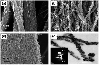 | ||
| Fig. 6 FESEM micrograph of electrospun ZnO nanofibers formed at two different calcination temperatures; 450 °C (a), 650 °C (b); (c) shows low magnified view of the ZnO nanofiber mat after and TEM image of ZnO nanofibers (d). The selected area electron diffraction (SAED) pattern shows the crystal planes (inset). Reprinted from ref. 55, copyright (2013), with permission from Elsevier.55 | ||
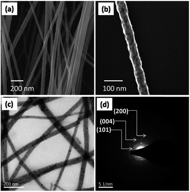 | ||
| Fig. 7 FESEM image of electrospun TiO2 nanofiber mat produced at 500 °C (a); (b) shows the higher magnifiedview of a single fiber; TEM micrograph of TiO2-nanofibers (c); and the SAED pattern presentation the crystal planes of anatase TiO2 (d). Reprinted with permission from ref. 56. Copyright (2014) American Chemical Society.56 | ||
3.4 Nanoribbons
In recent times, Feng et al. have fabricated various ultrathin nanoribbons/nano sheets of Fe2V4O13,96 Zn2GeO4,97 (shown in Fig. 8 with their FESEM, TEM, and HRTEM images) and nanosheets of Bi2WO6,98 TiO2/graphene,99 and WO3,100 and demonstrated them as very efficient and highly selective photocatalysts.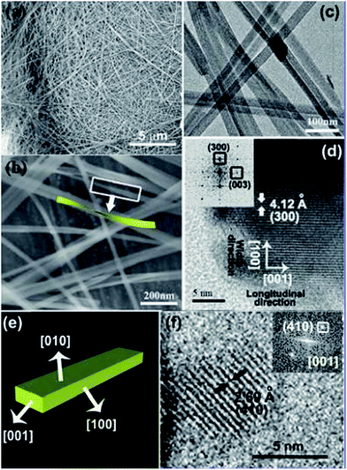 | ||
| Fig. 8 Zn2GeO4 nanoribbon nanostructures are described by (a and b) FESEM, (c) TEM, and (d) HRTEM images. Structural model of a nanoribbon shown in (e). (f) HRTEM micrograph imaged along [001] plane. The inset of (d) displays the FFT pattern achieved from the HRTEM micrograph. Reprinted with permission from ref. 97. Copyright (2010) American Chemical Society.97 | ||
The unusual high photocatalytic activity of the ultrathin nanostructure can be arises because of the thickness scale down to some tens of nanometer which offers a huge specific surface area and nanoscale geometry permits fast mobility of charge carriers from the inside onto the surface to contribute in the photocatalysis in compare with their bulky counter parts. Interestingly, a micron thick, ultra-thin Na2V6O16·H2O nanoribbon has been synthesized by the same group using hydrothermal technique and the nanoribbons was confirmed to significantly endorse the photocatalytic activity under exposure of visible light.101 In similarly context, Zhang's group102 has prepared well-dispersed boron-doped graphene nanoribbons and Shao's and his coworkers103 have developed single-crystalline α-MoO3 nanoribbons for efficient photocatalytic applications.
3.5 Other nanostructures
There are many other different nanomorphologies have been explored towards photocatalysis such as nanospheres, thin films, nanocone, nanoribbons etc. For example, Zhang et al.104 have been developed a method to produced porous TiO2 hollow nanospheres.The photocatalytic activities of the nanocatalysts were assessed by the photodegradation of methyl orange dye under UV irradiation. Their studies indicates that the TiO2 hollow nanospheres displayed outstanding photocatalysis, improved than that of commercial Degussa P25 in the existence of Cr(VI) owing to the elevated specific surface area. Recently, Bi and his coworkers fabricated Bi and BiAg alloy nanospheres via a simplistic hydrothermal route and demonstrated photocatalytic activity towards H2 generation.105 Zhou's group has reported a synthesis protocol for a of C@Ag/TiO2 composite photocatalyst by combining a hydrothermal and sol–gel method and claimed that the photocatalytic activity considerably boosted under visible light.106 In the context of composite nanostructured photocatalyst, Mondal et al.107 have been fabricated macroporous TiO2/polyacrylonitrile and TiO2/carbon hybrid films using spin coating technique. They have demonstrated that porous carbon film acts as a catalytic support material for the TiO2 nanoparticles with an average size 40 nm. The resultant TiO2/carbon hybrid porous films reveal outstanding photocatalysis as displayed for the degradation of aqueous rhodamine B dye.
4. Metal–semiconductor nanostructured photocatalysts
An indispensable requirement for the photocatalyst is its robustness to the reaction occurring at the solid/liquid interface, which can involve its physicochemical belongings. However, it has demonstrated hard to find an ideal photocatalyst, which encounters all the necessities like physicochemical stability, resistance to corrosion, harvesting visible light and appropriate band gaps that would enhance photocatalytic response as a viable alternative. Providentially, recent research in the field of nanoscience and nanotechnology has improved the alteration of obtainable photocatalysts and the finding and improvement of new materials.108,109 The fast growing number of scientific publications establishes vibrant bibliographical confirmation for the implication of this hot subject matter. Several papers considered the influence of diverse nanostructures of nanomaterials on their performance as photocatalysts, as their efficiency of energy conversion is mostly determined by nanoscopic properties.In this context, metal-oxide semiconductors are of excessive scientific significance in electronics and environmental remediation as they have competence to create charge carriers when irradiated with requisite expanse of energy. The encouraging organization of electronic arrangement, efficient light absorption capabilities, and interesting charge transport features of maximum of the metal-oxides has ended promising its use as photocatalyst. But, there are some drawbacks in semiconductor photocatalysts, such as, fast recombination of photogenerated chare carriers, wide bandgap which makes the possibility to engineer new composite photocatalysts.
The most important objective of designing composite photocatalyst is to modify the photoelectrochemical possessions of the semiconductor nanomaterials. A sequence of metal–semiconductor and semiconductor–semiconductor composite nanoparticles have been demonstrated to ease charge refinement in the metal-oxide semiconductor nanostructures.110–113 The noble metal can performs as a sink for photogenerated charge carriers and thus helps interfacial charge-transfer procedures in these composite photocatalysts.114 The schematic describing the electron transfer in noble metal–semiconductor photocatalytic system is shown in Fig. 9. In a latest report, research effort was ended to include noble metal ions to encompass the photoresponse of titania keen on the visible light radiation.115 A straight correspondence between the photocatalysis for the production of ammonia from azide ions and the work function of the metal has been prepared for metallized TiO2 systems has been described by Nosaka et al.116 Also, doping of TiO2 nanomaterials with transition metal ions has been explored by a number of researchers to increase the photocatalytic properties of metal-oxide semiconductor photocatalysts.117,118 An infrequent photoelectrochemical consequence has also been described for Ni/TiO2 photcatalyst in the form of films.119 These fascinating features of metal–semiconductor photocatalytic systems encouraged many research groups to probe the impact of metal nanoparticle on the photocatalytic properties of metal-oxide semiconductors.120
4.1 Metal–metal-oxide semiconductor heterostructure photocatalysts
Heterogeneous nanoparticles comprising two or more dissimilar functional units in epitaxial conjugation are of immense research concern since they possesses exclusive physicochemical, magnetic, electronic, optical, catalytic and photocatalytic belongings.121–123 These properties typically consequence from their nanoscopic junction effects existing in the structure. It is well-known that for a heterojunction between a heterostructured metal and metal oxide nanoparticle, the material characteristics at both ends adjacent to the interface are altered from their bulk counterpart. This could be instigated by various influences, comprising surface reconstruction nearby the junction, lattice mismatch persuaded crystal strain, and electron interaction/transfer through the interface. However, modifying material belongings by heterogeneous conjugation to a large degree depends on the epitaxial link between the two unlike materials.124,125 A typical metal–metal-oxide semiconductor heterostructure of Au–Fe3O4, Ag–Fe3O4, Pt–Fe3O4 and AuAg–Fe3O4 nanostructures are shown in Fig. 10.126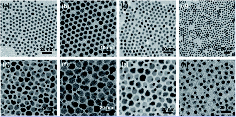 | ||
| Fig. 10 TEM micrographs showing different noble metal nanoparticles: 5 nm Au (a), 5 nm Ag (b), 5 nm Pt (c), 6 nm AuAg (d); noble metal–metal oxide heterostructures of 5–12 nm Au–Fe3O4 (e), 5–12 nm Ag–Fe3O4 (f), 5–12 nm Pt–Fe3O4 (g), and 6–10 nm AuAg–Fe3O4 (h) nanoparticles. Reprinted with permission from ref. 126. Copyright (2010) American Chemical Society.126 | ||
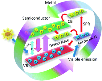
The metal–metal-oxide semiconductor nanostructured photocatalysts can be differentiate mostly in to two classes. Firstly, the materials is photoenergetic and, upon excitation, the excited charge carriers are shifted to further share of the material, which thereby prompts the catalytic method. The plasmonic nanomaterials such as gold, silver, platinum the grouping of elevated bandgap semiconductors like TiO2 fall in this group, where upon photoexcitation the plasmon electrons are transported from gold to the TiO2 semiconductor for starting the catalytic activity.127–132 These are identified as plasmonic photocatalysts which have been extensively studied and described in the literature. A probable electron removal from the surface plasmonic state of gold to the semiconductor material has been illustrated in Fig. 11 while connecting the recent literature.133–135 The second further option is that both the semiconductor and metal are photosensitized and captivate the solar light. The material systems where the plasmonic material gold is combined with small bandgap semiconductors (for example Au–CdS, Au–PbS, Au–CdSe, etc.),136–138 counted in this class.136 Interestingly, it is perceived that there is a chance of the electron transfer from both ends, i.e., either metal to semiconductor or the reverse subjected to the bandgap arrangement along with the excitation basis.
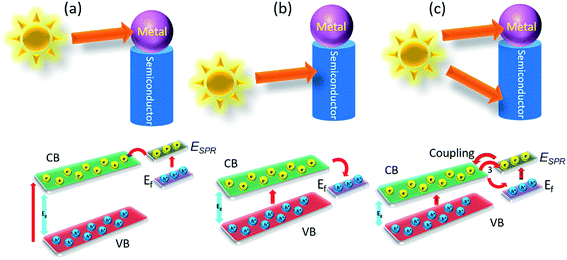 | ||
| Fig. 11 Schematic representation of the electron transfer process in a metal–semiconductor heterostructure. | ||
In certain occasion, if only the metal is excited, then electron handover can trail alike to the scheme shown in Fig. 11a, providing the surface plasmonic state rests above the conduction band (CB) of semiconductor. In the same way, with selective excitation of the semiconductor can ease the electron movement from CB to the electronic band of gold and a schematic presentation of such electronic movement has been shown in Fig. 11b. But then, the circumstance turn out to be further complex once both semiconductors and metal are photo excited simultaneously (shown in Fig. 11c). Despite the fact utmost of the information anticipated the photoexcited electron assignments from the agitated state of semiconductor to plasmonic metal, but few latest research on gold–cadmium sulfide metal–semiconductor exhibited that, the electron assignment in together traditions are probable, yet more probable is the handover from CdS toward Au. The coupling of the exciton is also possible between semiconductor and plasmon of metal.138–140 Conversely, it is demonstrated that the occasion when both the semiconductor and metal are photoexcited, it turns out to be more encouraging, as they together can captivate solar radiation and produce more photoexcited charge carriers than the rest two kinds. On the other hand, even though most of the cases it is considered for metal–semiconductor heterostructures, but besides gold, further metals are also been coupled with many semiconductors and can be employed in efficient photocatalysis. For example plasmonic platinum has been considered even further effective in few circumstances.141,142 But mostly the metallic Au is used for metal–semiconductor photocatalyst systems as this one has surface plasmon resonance (SPR) which falls in the strong vicinity of the solar spectrum.
4.2 Metal–metal oxide semiconductor core–shell nanostructured photocatalysts
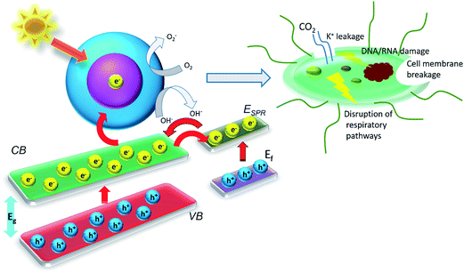
In recent past, there have been made noteworthy advances in the designing of core–shell metal–semiconductor photocatalysts.143–147 Until now, the struggles to employ these core–shell nanostructures as photocatalyst materials in the photoenergy renovation systems such as hydrogen generation, water splitting, photoelectrochemical cells, photocatalysis of wastewater etc. are restricted.In this context, it is imperative to interpret the effect of the metal core on the photocatalytic belongings of exterior metal oxide shell (shown in HRTEM micrograph of an individual Au–Cu2O core–shell nanostructure along with its SAED patterns in Fig. 12a and b respectively). As a distinctive class of innovative core–shell photocatalysts, metal-core and semiconductor-shell nanocomposites are capable of doing noteworthy advantages as a candidate in heterogeneous photocatalysts. Firstly, encapsulating metal nanoparticles inside a metal-oxide semiconductor outer shell can significantly improve their stability in contrast to agglomeration, and help to escape unwanted photo corrosion or suspension in the course of the process of catalytic reactions in real uses.148,149 Secondly, as per the core material being a noble metal, its small Fermi energy level can function as a pool of photo generated electrons and extend the lifespan of photogenerated charge carriers. Thus this phenomenon perhaps increases the total photocatalytic performance.4,120,150,151 These features have been well described by Kamat's and his coworkers, which can be realistically explained by a semiconductor–metal nanocomposite system as shown in Fig. 13.127,143,152 Furthermore, the core–shell nanostructural design offers a 3D close interaction between the semiconductor shell and metal core which takes most advantage of the metal-support interfacial interaction. In this manner it eases the interfacial charge transfer procedure.143 Lastly, the metal–metal-oxide core–shell nanostructured configuration delivers a homogeneous photocatalytic environment for reactions to continue.153,154 These exceptional advantages essentially accompanying with the metal-core and metal-oxide semiconductor-shell nanocomposite photocatalysts propose that they can be employed as a innovative approach for light harvesting in heterogeneous photocatalysis.
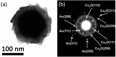 | ||
| Fig. 12 (A) TEM micrograph of an individual Au–Cu2O core–shell nanoparticle with a compact metal oxide shell and (B) SAED pattern showing individual crystal planes. Reprinted with permission from ref. 155. Copyright (2012) American Chemical Society.155 | ||
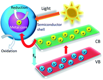 | ||
| Fig. 13 Scheme of a light-induced charge separation mechanism in a typical metal–metal oxide semiconductor core–shell in a photocatalytic reaction. | ||
4.3 Synthesis of metal core–metal oxide shell photocatalysts
The designing of metal core–metal oxide shell nanostructures needs full control over some processes parameters, including nucleation and growth in the semiconductor shell nanostructure surrounding the seeds of metal-core nanoparticles. These routes are controlled by means of various experimental factors, for example, temperature, time, solution concentration, mismatch in lattice parameters, presence of surfactant, interfacial energy, and so on.Usually, the mismatch in lattice parameters and shortage of chemical interaction between metal–metal oxides interfaces frequently consequences in a huge interfacial energy generation between the metal oxide and a metal. Unfortunately, if there exists a lattice incompatibility between two constituent materials then that would be very problematic to create their core–shell formation. Yet, suitable ligand or surfactant might be helpful to adjust the interfacial energy between these two constituent materials. The nanoparticle assembly with the noble metal core and SiO2 shell is quite recognized, however, this technique has not been widely applied to other oxide shells, mostly for the reason of agglomeration in the solution.156 Furthermore, syntheses of various metal oxides, excluding silicon dioxide, need the usage of metal precursor salt, which could lead to aggregation of the nanoparticle seeds. Although, if the consumption of metal salt as a precursor is inevitable, the introduction of proper surfactant, ligand etc. can be an alternative favorable solution to synthesize core–shell nanomorphology. Therefore, the choice of a friendly ligand or surfactant remains interesting, and thus there are very few literature exist reporting the synthesis of core–shell nanoparticles with metal oxides, even if their analogous pure oxides are available commonly. This is a probable the cause why the core–shell nanoparticles with metal and metal oxides is case specific. The fabrication of TiO2 and SnO2 core–shell nanoparticles is comparatively much easier as both of them have cubic crystal structure comparable to silver, gold, platinum etc. noble metals, and as a result, there has exists a good match in lattice parameters for core–shell construction in this combination. However, it is very difficult to create a ZnO nanostructure surrounding a noble metals to design core–shell structure since ZnO is hexagonal and differently grows along c-axis. In consequence, the formation of core–shell structure by metal–ZnO combination was challenging owing to their lattice mismatch and very unfortunately neither a surfactant nor a ligand can help to overcome the encapsulation problem during synthesis.157 As a solution to this problem, recently, Zhao et al.158 have fabricated Ag–ZnO core shell nanoparticles by laser ablation technique nanoparticles and proposed that synthesized nanoparticles may have outstanding application towards micro-nano optoelectronic device fabrication. They have synthesized for the first time a silver–ZnO core–shell by a 248 nm KrF excimer pulsed laser ablation in a liquid solution. It was observed that Ag–ZnO core–shell nanostructures show strong surface plasma resonance absorption and that can be altered by tuning the thickness of the ZnO shell. Also, Sun et al.159 have successfully produced metal–ZnO core–shell structure with distinct morphology and obtained a comprehensive growth mechanism (Fig. 14a–f show TEM images and photographs of metal–ZnO core–shell nanostructures that were produced from different noble metal used as cores). They have established a general scheme for coating ZnO on various core metals, oxides, polymer nanoparticles, graphene oxide, and carbon nanotube seeds. They have also shown that this technique works well and can be further extended to include many other semiconductors like Fe3O4, MnO2, Mn3O4, MnO, Co2O3, TiO2, Eu2O3, Gd2O3, ZnS, Tb2O3, CdS and β-Ni(OH)2, as the shell materials (shown in Fig. 15a–i). It was observed that polyvinylpyrrolidone (PVP) and 4-mercaptobenzoic acid played an imperative role in the Au–ZnO synthesis. They have also revealed that 4-mercaptobenzoic acid can substantially decrease the Au–ZnO interfacial energy. Although, ZnO does not cooperate well with the hydrophobic ligands attached to the surface on the gold in the absence of PVP polymer demonstrating that the amphiphilic nature of PVP is crucial in the ZnO encapsulation on the metallic core with hydrophobic ligands.
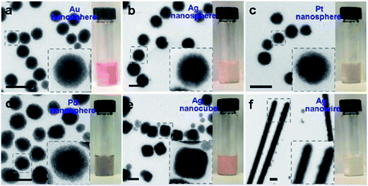 | ||
| Fig. 14 TEM micrographs and digital photographs of metal–ZnO nanoparticles that were made from diffrent noble metal cores: citrate-stabilized nanoparticles, including nanospheres of Au (a); Ag (b); and Pt (c). PVP-stabilized nanoparticles, including nanospheres of Pd (d); Ag (e); and Ag nanowires (f) (diameter = 120 nm, length = 3–5 μm). Insets display magnified views of typical nanomorphologies. All scale bar: 200 nm. Reprinted with permission from ref. 159]. Copyright (2013) American Chemical Society.159 | ||
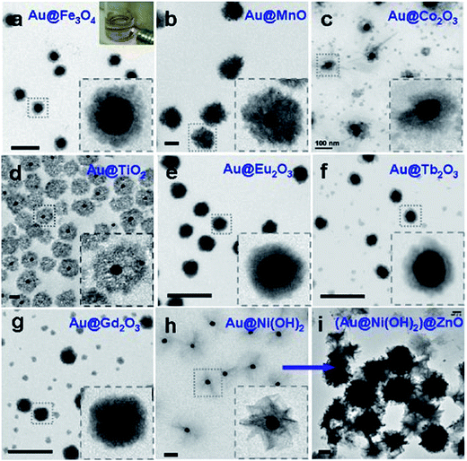 | ||
| Fig. 15 TEM micrographs of Au-oxide nanoparticles (diameter of Au = 40 nm) with different types of metal oxide shell materials: Au–Fe3O4 (a), Au–MnO (b), Au–Co2O3 (c), Au–TiO2 (d), Au–Eu2O3 (e), Au–Tb2O3 (f), Au–Gd2O3 (g), Au–Ni(OH)2 (h), and (Au–Ni(OH)2)–ZnO (i). Insets describe magnified views of typical nanoparticles. All scale bar: 200 nm. Reprinted with permission from ref. 159. Copyright (2013) American Chemical Society.159 | ||
Interesting core–shell structure with Ag metal and WO3 metal-oxide nanostructures were synthesized by a hydrothermal method for effective localized surface plasmon propagation by Liu's group.160,161 Size and shaped dependent silver nanoparticles with diameter in the 25–60 nm range have been prepared successfully. First, Ag nanoparticles were dispersed into a Na2WO4 solution and then after adding nitric acid Agx-H2WO4 was precipitated in the solution. A high temperature calcination process then employed and removes water from the precipitate to form Agx–WO3 core–shell nanostructure where the shell thickness was ∼60 nm in a ∼200 nm overall particle size.
In a recent study, Lu et al.162 have been demonstrated a robust room-temperature wet chemistry methodology to fabricate hollow Au–Cu2O core–shell nanostructures where they can control the regulation and augmentation of plasmonic properties of cores (hollow gold nanoparticles) via tuning the nanosized dielectric Cu2O shells. It was evident that, the epitaxial growth of Cu2O on the Au nanoparticle surface happens because of the good affinity of Cu2O to gold surface and their comparable crystal symmetry. Fig. 16a–d show typical TEM micrographs of hollow core–shell nanomorphology of Au–Cu2O particles with increasing shell thicknesses and Fig. 16e describes the size distribution.
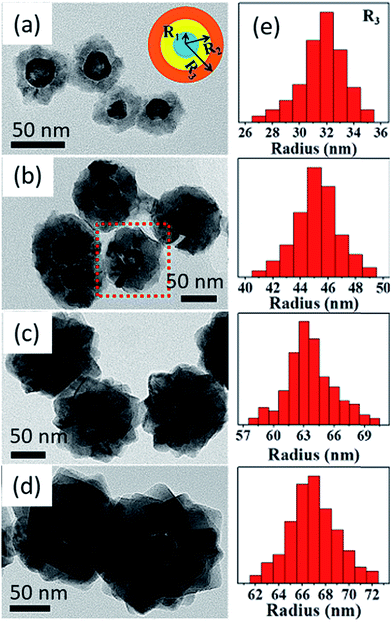 | ||
| Fig. 16 TEM micrographs of hollow Au–Cu2O core–shell nanostructures with adjustable shell thicknesses. The inset in (a) shows the scheme of cross-sectional drawing of core–shell nanoparticle where R1, R2, and R3 are the average inner radius and outer radius of core and overall radius of core–shell structure, respectively. The thickness was tuned by mixing different volumes of colloidal hollow gold nanospheres in the reaction (a) 1.8, (b) 1.0, (c) 0.4, and (d) 0.3 mL. (e) Histogram describing size distribution (R3) of the aforesaid core–shell nanoparticles with different of Cu2O shell thicknesses. Reprinted with permission from ref. 162. Copyright (2016) American Chemical Society.162 | ||
There are very few information on the realization of core–shell nanoparticles using Co3O4 as shell material. In this context, Hu et al.164 the synthesized Au–Co3O4 core–shell nanocubes via solvothermal process, however, there is no strong indication of core–shell nature in these nanostructures. Xu's group has been reported a simplistic synthesis method to attain a Pd–CeO2 hollow core–shell nanostructures made up of Pd nanoparticle cores coated with CeO2 hollow shells.165 Kim and other co-workers have fabricated Au–Co3O4 core–shell nanowires.166 Recently, Yan's group reported the preparation of monodisperse Au–Co3O4 core–shell nanostructures, where final structures produced from the oxidation of monodisperse Au–Co core–shell nanocrystals and explored their catalytic activity for oxygen evolution application.167 Zhang et al.163 reported metal–Al2O3 yolk–shell nanostructured particles with improved thermal stability where metal nanoparticle is confined inside alumina nanoshell. They have employed a one-pot hydrothermal reaction to prepare a core–shell structure of metallic core surrounded by carbon shell and that was then used as seeds for the subsequent surface growth of Al2O3. Fig. 17 shows the TEM images of Au/carbon/Al2O3 nanostructures where in Fig. 17a and b, confirms that the diameter of carbon shell rise to 200 and 300 nm when extending the hydrothermal reaction. It is worth mentioning that, varying the parameters like aluminum salt concentration and the reaction time, the Al2O3 nanoshell thickness could be tuned (shown in Fig. 17c and d). In the same context, Huo's group has demonstrated the simplistic approach for encapsulation of prefabricated nanoparticles into carboxylic acid mediated metal–organic framework using metal–metal oxide core–shell nanoparticles as the self-template.168 The yolk–shell surface morphology of the reaction product was characterized by TEM and STEM which are shown in Fig. 18a–c. They have shown that the core–shell nanoparticle-metal oxide self-template could be converted yolk–shell metal–metal oxide heterostructures with preferred encapsulating functional materials and metal oxide shells. The thickness of the shell, encapsulated materials, and encapsulated nanoparticles in each petalous heterostructure, all of them could be tuned straightforwardly by varying the concentration of copper salt, the nature and concentration of used nanoparticles during synthesis of the Au–Cu2O core–shell NPs (shown in Fig. 18d–g).
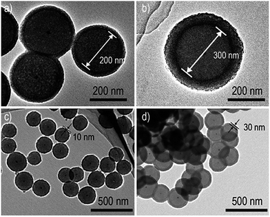 | ||
| Fig. 17 TEM micrograph shows Au/carbon/Al2O3 (a and b) different carbon sphere diameter and several alumina shell thickness (c and d). Reprinted with permission from ref. 163. Copyright (2015) American Chemical Society.163 | ||
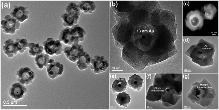 | ||
| Fig. 18 Surface morphology of yolk–shell nanoparticles petalous heterostructures: (a and b) TEM micrographs and (c) STEM dark-field micrograph of the Au petalous heterostructures displaying good product concentration and consistency. TEM micrograph shows the heterostructures encapsulating (d) a single gold nanorod, (e) a single Au nanoparticle, (f) a single Pd nanocube, and (g) several Pd nanocubes, respectively. Reprinted with permission from ref. 168. Copyright (2014) American Chemical Society.168 | ||
Transition metal core–semiconductor shell nanoparticles are also important candidate in this topic. For example, Chang et al.169 have been reported the synthesis of a Cu–ZnO metal–semiconductor core–shell nanoparticles containing Cu nanoparticles as core with an average diameter of 44.4 ± 4.3 nm and coated with 4.8 ± 0.5 nm-thick ZnO nanoshell. Chen's group has been reported a new and facile route to develop the fabrication of Zn–ZnO core–shell metal–semiconductor nanostructures on a large scale.170 Recently, Kudrynskyi's group has been reported a route for the controlled synthesis of greatly ordered core–shell nickel–carbon nanoparticle arrays.171 Ivanov et al.172 have been synthesized core–shell nanowires with a Fe core coated by an iron oxide shell via a facile low-cost fabrication method. They have demonstrated that the magnetic properties of the core–shell nanostructures can be altered by changing magnetite shell thicknesses to obtain significantly multi-functionality and new properties.
Interestingly, metal–metal oxide core–shell nanoparticles systems sometime confirmed photocatalytically more effective owing to the fact of doping of the core–shell systems, such as doping in TiO2 shell by Zn, F, S or C etc., nanoparticles. For example, it has been observed that a simple doping in TiO2 with Zn173 or F174 gives higher photocatalytic activity in systems with Pd–TiO2 nanoparticles. Recently, Er3+, Yb3+ doped core–shell nanostructured BiVO4 and their near-infrared photocatalytic prospects have been reported by Shan's group.175 Along the same concept, Pihosh et al.176 have doped WO3 into BiVO4 system and have reported enhanced photocatalytic activity.
Moreover, core–shell nanostructures with other metals and metal oxides have also been described, but, many of them do not have well-defined core–shell structures and failed to achieve uniform particle sizes.
5. Environmental applications of the core–shell photocatalysts
Semiconductor nanostructured mediated photocatalytic degradation of organic pollutants have revealed excessive prospective as a wastewater management technology. This method can be employed to eliminate persistent organic compounds and various micro-organisms that are involved water pollution, and it has been established extensively.177–181 Semiconductors are encouraging catalysts for this technology since they are environmentally friendly and can perform great photocatalysis of waste at small cost in ambient conditions.182 Although, there are few disadvantages to the usage of semiconductors photocatalysts that bounds their wide spread acceptability for extensive photocatalytic developments. For example, they have a high rate of recombination of photogenerated electron–hole charge pairs and on top of that they show poor recovery after photocatalysis.To address both issues with photocatalytic semiconductors, core–shell nanomorphology of the metal–semiconductor photocatalysts is a feasible option. Nanaoscopic metal core and semiconductor shell are able to decrease the rate of recombination rate of electron–hole pairs. Without a doubt, there is a fast transfer of electrons from the conduction band of the semiconductor to that of the metal and slow recombination of charge carriers as there is defect sate created below the conduction and above the fermi energy levels owing to the metal–semiconductor bandgap modification.183 A summary of the nanostructured metal–semiconductor core–shell phtocatalysts and their use towards various environmental applications based on visible and UV light mediated photocatalysis is explained in Table 1.
| Core–shell photocatalyst | Average particle size | Light irradiated | Application | Literature |
|---|---|---|---|---|
| Au–TiO2 | 100 nm (core–Au (25 nm)) | UV | Photocatalysis of ethanol | Goebl et al.184 |
| Au–Cu/TiO2 | 5.4 nm (core–Au (4.5 nm)) | Visible | Selective oxidation of amines | Sato et al.185 |
| Pt–SnO2 | 12 nm (core–Pt (7 nm)) | Visible | Degradation of formaldehyde | Chang et al.186 |
| Pt–TiO2 | 90 nm (core–Pt (30 nm)) | Visible | Photocatalysis | Fang et al.187 |
| Ag–TiO2 | 15 nm (core–Ag (5 nm)) | UV | Destruction of methylene blue | Chen et al.188 |
| Ag–TiO2 | 37.33 nm (core–Ag (33.63 nm)) | UV and visible | Degradation of azo dyes in wastewater | Khanna et al.189 |
| Ag–SiO2/TiO2 | 80 nm (core–Ag (60 nm)) | Visible | Photocatalysis | Zhang et al.190 |
| Ag–Cu2O | 100 nm (core–Ag (31 nm)) | Visible | Photocatalysis | Li et al.191 |
| AgAu alloy–TiO2 | 30 nm (core–Ag (10 nm)) | UV | Photocatalysis of methylene blue | Xiao-yu et al.192 |
| Ag–ZnO | 100 nm (core–Ag nanowire (83 nm)) | Visible | Degradation of rhodamine B | Xiong et al.193 |
| Ag–ZnO | 15 nm (core–Ag (10 nm)) | Visible | Disinfection of bacterium Vibrio cholerae 569B | Das et al.194 |
5.1 Wastewater treatment and air purification with core–shell nanostructured photocatalysis
Conventional metal-oxide photocatalysts have been widely considered for wastewater management and polluted air purification application and it is well acknowledged to be an active scheme to treat a number of hazardous materials in polluted water and also the air. More emphasis is specified at the present time to core–shell metal–metal oxide-based photocatalysis and their use concerning the remediation of controlled and emergent pollutants of concern. Owing to the dissimilarity between the atomic electronegativity, the metallic nanostructured layer in the double-layered configuration helps the photogenerated charge transfer of in the conduction bands of the semiconductor photocatalyst, permitting electrons to counter with reactants efficiently.Recently, since silicon nanowires have been confirmed to be very useful in the degradation of organic dyes by photocatalysis, Jiang and coworkers195 have studied a system where they have fabricated Si/SiOx metal–semiconductor photocatalyst and applied for wastewater treatment. They have purposely designed SiO2 shells on the surface of Si nanowires to yield Si/SiOx core–shell nanowire photocatalyst. The photo degradation study was done on indigo carmine dye which is a model organic contaminant in wastewater and interestingly the core–shell photocatalyst was observed to be very active towards the photocatalysis. In another study, Zhang's group196 has prepared Zr-doped silica shell/titania core nanoparticle photocatalyst through extended channels into polyvinylidene fluoride (PVDF) membrane to improve mass transfer depending on immobilizing and recycling TiO2 in the course of photocatalysis of methyl orange dye solution and oil in wastewater comprising oil, respectively. They have demonstrated that the photocatalytic membranes own encouraging requests in the immobilization and recycling of photocatalysts with improved photocatalytic activity for wastewater treatment. It can be interesting to note that Xu's group4,197 is the foremost one who has fabricated noble metal core and semiconductor shell nanostructured photocatalysts and put on them as a photocatalysts for selective oxidation of alcohols to aldehydes. They have synthesized an aqueous phase Pt–CeO2 photocatalyst with controllable core–shell and yolk–shell nanomorphologies by template-free hydrothermal method which can assist as a competent visible light driven photocatalyst towards wastewater treatment.
Additionally, to the examples with core–shell nanocomposites as photocatalysts for wastewater treatment and selective oxidation reaction stated earlier, Liu and other coworkers199 have designed a Ni–NiO core–shell nanostructure modified with nitrogen doped InTaO4 photocatalyst and explored its photocatalytic action for the choosy reduction of CO2 to methanol which is as example of treatment of pollutant air via photocatalyst. They have fabricated InTaO4 followed by its sintering in an ammonia atmosphere at reasonably high temperature for confirming nitrogen doping. The nitrogen doped catalyst Ni–NiO/InTaO4–N shows the maximum photocatalytic activity as compared to without doped one under the exposure of visible light rendering to the rate of methanol formation. The improved photocatalysis can be attributed due to three causes. First, doping of nitrogen can thinner the band gap of core–shell InTaO4 photocatalyst, thereby growing both the wavelength and the quantity of light energy absorbed. Second, the O2 atoms could be substituted by the nitrogen atoms due to doping, causing in the creation of some oxygen vacancies, which are important to augment the photocatalytic activity. Lastly, chemical alteration of InTaO4–N by putting the Ni–NiO core–shell constituent will give rise to an additional photoactivity enrichment. Rabbani's group200 has developed a Zn–Fe2O4@ZnO core–shell structured hollow nanospheres and demonstrated their visible light photocatalytic activity by degradation of methylene blue dye. The study reveals that due to magnetic properties Fe2O4 the catalysts are very efficient and easily recyclable. Recently, Singh et al.198 studied the mesoporous, hollow TiO2 nanofibers fabricated by coaxial electrospinning method for the photocatalytic decomposition of para-nitrophenol (4-NP) dye which is a familiar model water pollutant dye. They have sensitized hollow titania nanofibers by cadmium sulphide (CdS) quantum dots (QDs) over successive ion layer adsorption and reaction (SILAR) technique for different deposition cycles (the fabricated nanofibers are shown in Fig. 19a–h). The CdS QDs loaded hollow titanium dioxide nanofibers yield catalytic spots at the QDs and TiO2 interface which benefits in improved exciton separation. It was reported that TiO2/CdS photocatalyst for 3 SILAR deposition cycles is three times more photocatalytically efficient than hollow TiO2 nanofibers and eight times effective than the pristine solid nanofibers.
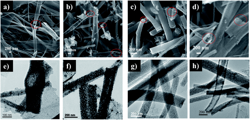 | ||
| Fig. 19 FESEM images (a, b, c and d) showing CdS loaded TiO2 hollow nanofibers after 1, 2, 3 and 5 SILAR cycles, respectively (marked regions show the hollow morphology of nanofibers); TEM images (e, f, g and h) reveal CdS loaded TiO2 hollow nanofibers after same SILAR cycles, respectively. Reproduced with permission from ref. 198. Copyright 2016, Royal Society of Chemistry.198 | ||
5.2 Water disinfection with core–shell photocatalysts
Over the past few years visible light induced photocatalytic decontamination of wastewater has gained substantial research consideration.201–203 Various semiconductor photocatalysts have also been explored for a variety of decontamination uses, together with water cleansing. Thirty years later Matsunaga et al.204 reported the first work regarding disinfection of wastewater using titania/Pt nanoparticles photocatalysis for a variety of organisms (Lactobacillus acidophilus (bacteria), Saccharomyces cerevisiae (yeast), and Escherichia coli (bacteria), Yu et al.205 published paper on decontamination of the wastewater containing Gram positive bacterium Micrococcus lylae. In this work sulfur doped TiO2 was irradiated to 100 W tungsten halogen lamp and wavelengths less than 420 nm eliminated using a suitable glass filter.The study (Saito et al.206) revealed that that photo activated photocatalysts triggered split of the cell membrane of the microorganisms, as shown in representative Fig. 20 and validated by intracellular leakage of K+ ions that correspondence to cell damage. Added confirmation of this microorganism cell death mechanism was establish by Sunada and co-workers,207 who showed that semiconductor mediated photocatalysis damage of endotoxin, an vital constituent of the external membrane of bacteria. Maness et al.208 further revealed that the existence of lipid peroxidation and the concurrent damage of both membrane-dependent respirational movement and cell feasibility rigorously rest on both the exposed light energy and photocatalyst. It has also been studied (by Huang et al.209) the positions of cellular destruction and their impact to cell death in Escherichia coli with photoexcited titanium dioxide catalyst particle. Her it was suggested that the surface of photocatalyst first creates contact with whole cells and immediately after the oxidative destruction happens to the cell wall. Once the photocatalysis gradually amplified cell permeability and then subsequently, open up intracellular constituents, and permits the catalyst nanoparticles an easy entrance and photo-oxidation of intracellular components, thus speed up the cell death209,210 (as shown in Fig. 20).
It is well acknowledged that UV radiation creates damage in DNA, however, once cell wall mutilation is instigated by the photo-oxidation of photocatalysts, they can also yield further damage to the intracellular modules.211,212 In light of this context, Hidaka and co-workers213 implemented in vitro tests and monitored the outcome of DNA, RNA, and their purine and pyrimidine bases as soon as exposed by UVA light in presence of photocatalyst nanoparticles. Interestingly, till to date, the photochemical biocidal mechanism is mostly unclear.214 It is still unclear what exact reactive oxygen species are openly intricate the photocatalytic cell killing procedure, particularly the characteristics of the key reactive oxygen species (ROS), which not only contain the OH˙, but also H2O2, and O2−. Interestingly, Ag–ZrO2 core–shell photocatalysts have also prepared very recently and verified for the antibacterial property towards various organisms (Escherichia coli and Staphylococcus aureus) and the antifungal effect against Candida glabrata, Candida albicans, Aspergillus flavus, and Aspergillus niger fungi by the agar diffusion technique.215 DNA intercalation studies were also performed in CT-DNA in presence of the photocatalyst. The study reveals that semiconductor ZrO2 supported on the Ag nanosurfaces not only prohibited agglomeration of nanoparticles, but also showed superior DNA intercalation and antimicrobial activity than the pristine silver nanoparticles which could have encouraging application as antimicrobial materials for microbicides disinfection in wastewater. Meena et al.216 demonstrated core–shell Au–SiO2 metal–semiconductor nanoparticles by Stober's synthesis and their result reveals that improved core–shell nanoparticles nanostructure displays that the formation of singlet oxygen. The cell viability of the core–shell nanoparticles in contrast to HeLa cell lines were deliberated by MTT assay technique. The consequences of their study point out that, the Au–SiO2 core–shell nanoparticles are enormously stable with a high photodynamic efficacy in visible light.
Recently, Karunakaran's group has been synthesized core/shell Fe3O4/Ag–ZnO nanostructured composite photocatalyst nanoflakes via hydrothermal method followed photodeposition technique.217 The magnetically recoverable core–shell catalyst was used for photocatalytic and antibacterial activities for dye-degradation and E. coli bacteria disinfection. In another study, Dhanalekshmi et al.218 have prepared core–shell type Ag–TiO2 nanoparticles of size <50 nm by reduction of silver nitrate salt and hydrolysis of Ti(IV) isopropoxide. The antibacterial properties of Ag–TiO2 core–shell nanostructured photocatalysts were demonstrated towards Escherichia coli and Staphylococcus aureus bacteria disinfection in wastewater. They have claimed that Ag helps in antibacterial activity while TiO2 serves the photocatalytic activity in contaminated water. The have also compared the antibacterial activity of Ag–TiO2 core–shell with Ag–SiO2 core–shell photocatalysts and demonstrated that the antibacterial action of Ag–SiO2 is greater than the Ag–TiO2 owing to their superior surface area.219 Positively charged core of Ag nanostructures responded straightforwardly with Gram negative bacteria reasonably than gram positive bacteria and further successfully killed Escherichia coli and Staphylococcus aureus. Antimicrobial activity of nanocomposite TiO2–NiFe2O4 with a photocatalytic titania shell covering a magnetic nickel ferrite core is reported by Misra's group.220 TiO2-coated NiFe2O4 nanoparticle photocatalysts display remarkable anti-microbial activity when brought near UV light irradiation. It was also found that the bacterial disinfection reaction of anatase TiO2 coated nickel ferrite is greater than brookite phase of titania, even when the photocatalytic reaction rates are identical.
5.3 Other applications of metal–semiconductor core–shell nanostructures
Core–shell nanoparticles can be used in other fields like reusable supply, prosthetic kit, dental devices, implant material, wound dressings, external corporeal devices, encapsulating medium, devices nanoparticle-polymeric drug delivery, tissue engineering, and other biomedical applications. Additionally, the core–shell nanostructured materials have revealed an extensive range of new requests in the fields of biochemistry, biomaterial sciences due to their better physicochemical behaviors. Core–shell nanomaterials also play vital parts in emerging medical and biological uses. Suitably designed core–shell structures can deliver biocompatibility, environmental safety, and better surface functionalization that is compulsory for particular applications in vivo and in vitro systems. For example, cancer and tumor treatment is a well-known field where core–shell nanomaterials have proved their ability. In light of this, we know that in case of treatment of hyperthermia with size-dependent iron oxide magnetic nanoparticles (SIONPs) comprises a local rise in temperature up to 45 °C when the magnetic nanoparticles are subjected to a strong external magnetic field. Such an increase in temperature could be deadly for temperature-sensitive biological cells, for instance cancerous cells. Modern studies by calorimetry confirms that the rate of heating depends on the size of the SIONPs. Thus the nanoparticles should be fabricated which have optimum particle size with narrow-size distribution for improved hyperthermia treatment.221There are also some reports about the toxic and cytotoxic potential of core–shell hybrid nanostructured systems. Guo et al.222 have prepared sulfhydryl-modified Fe3O4–SiO2 core–shell magnetic nanocomposites to evaluate their toxicity in vitro, and demonstrate their potential application in the biomedical fields. Atif et al.223 demonstrated in vitro cytotoxicity of mesoporous SiO2–Eu(OH)3 core–shell nanospheres in human breast cancer cells (MCF-7). Also, Fan's group has reported the synthesis of multifunctional Fe3O4@SiO2-GdVO4:Dy3+ core–shell nanoarchitecture and characterize for their cytotoxicity property as an efficient drug carrier.224
Recently, Sharma et al.225 have fabricated monodisperse iron–iron oxide core–shell magnetic nanoparticles and have been investigated their uptake by the cancer cells (LX-1 small cell lung cancer) and the stability in aqueous solution. Their findings have shown that core–shell metal–metal oxide semiconductor iron nanoparticles are very resistive to oxidation even after one week in presence of water, corroborating these nanoparticle assembly is a potential candidate for cancer treatment by hyperthermia.
6. Photocatalyst recycling
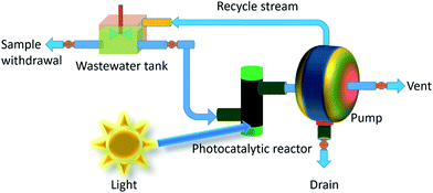
A mechanical pump is placed between the reactor and the reservoir for pumping the reactant via a flow-through cuvette located inside a photometer for nonstop on-line data collection of the catalyzed product (shown in Fig. 21). The reactor is consists of quartz glass tubes layered on its exterior surface with catalyst particles. The photocatalytic reactor is designed in such a way so that it could get sufficient dose of light energy. Few glass valves are used between the water and reactant reservoir for primary null setting of the analytical instrumentation part prior to the start of an experiment, feed of the reactant into the system, removal of air bubbles occurred throughout the reaction cycle, and finishing purging of the complete system.The semiconductor photocatalyst can be introduced into reactor either in a colloid form or in the form of an immobilized film. In a typical photoreactors run with catalysts in the form of slurry, the reaction rate is mostly controlled by the intensity of exposed light on the catalyst surface, the quantum efficiency of the photocatalyst particles and the adsorption nature of the reactant and non-reactant species present in the reaction environment.226 On the other hand, the usage of suspended catalyst needs the separation and recycling of the nanocatalyst from the treated solution and can be a difficult, time intense costly method.227 Furthermore, the penetration depth of UV radiation is restricted for the reason that of strong absorptions by both the catalyst and thawed organic compounds. These difficulties could be escaped in photocatalytic reactors where catalyst nanoparticles are immobilized on a support material, however, immobilization of photocatalyst particles on a supporter creates a distinctive difficulty. Since the reaction happens at the solid–liquid interface and mass transfer from the catalyst surface to the reactant may now hindered and could make the process slower. However, the design of reactor, use of high surface area porous supporter and suitable nanostructured catalyst along with their recycling process is essential for an efficient wastewater management.
The reusability and recovery of the catalyst is a vital issue in photocatalysis ever since it can subsidize considerably the operating cost of the treatment process, therefore making photocatalysts recyclable is a striking way for wastewater treatment. In this context, several repeated decolonization of waste are accomplished, for each time the same catalyst is used and with a fresh waste solution.
Membrane filtration is a smart tactic for solvable catalyst recycling. Applications of nanofiltration and ultra-filtration have established their excessive prospective as a technique for process intensification in organic, enzymatic, and homogeneous catalysis, both in laboratory exercise and on an industrial scales.228 Continuous flow nanofiltration is an interesting option for photocatalyst recycling. In addition to the catalyst recycling, continuous process operation with a combined membrane filtration can have many advantages. As of an economic perspective, an integrated process such as a continuous flow membrane reactor can be helpful towards lowering entire investment costs and total energy consumption. With regard to the chemistry point of view, the nonstop withdrawal of product can reduce conceivable product inhibition and undesirable repeated reactions. This may end result in greater reaction rates and a cleaner stream of product by simplifying product isolation. Interestingly, organic, aqueous or organic/aqueous photocatalysis permits stress-free separation of a homogeneous catalyst from the product phase, but is frequently incompetent when hydrophobic substrates are employed. A recycling system based on switchable water biphasic in presence of CO2 and is single phase in the absence of it. Photocatalysis can be executed first in the single phasic solvent, and then swapped to a biphasic system, extracting catalyst from product phase. Upon removal of CO2 permits an easy recycling of the catalyst particles. The catalyst could be recycled numerous times with minimal loss of catalytic activity.229 In this context, Myakonkaya et al.230 have demonstrated a method for separation, recycling and reuse of a highly-active Au and Au–Pd nanoparticle catalysts using the practically simple method of solvent quality tuning. In another study magnetic metal-oxide core (Fe3O4) and polymeric shell (PVA polymer) nanoparticles were efficaciously prepared and conjugated with heparin (HEP) in order to offer anticoagulation. The magnetic properties of the core–shell nanostructured catalysts helps in easy recycling by applying magnetic fields.231 Furthermore, magnetic nanostructured powders and nanostructured arrays films are other two kinds of photocatalysts which could be recycled easily. Most recently, Zhang et al.232 have been reported magnetic properties of CoFe2–CoFe2O4 core–shell composite nanopowder formed via oxidation route. Interesting core–shell nanostructure in a Ge0.9Mn0.1 magnetic film has also been demonstrated by Réotier et al.233 Similarly, 1D magnetic Ni/Ni3C core–shell nanoball chains with an average diameter ∼ 30 nm were produced via a mild chemical solution route by Chen's group.234
7. Conclusions and future prospective
After reviewing the latest representative literature reports, the role of various metal–semiconductor core–shell nanostructured photocatalysts towards environmental remediation application. It was found that there are different varieties of core–shell nanostructures. Depending on the selection of core and shell materials they can be categorized in several types like metal, nonmetal, semiconductor and polymers etc., core–shell nanostructures. The core–shell particles are reasonably stable and could retain their structural integrity when redisposed in aqueous medium. The core–shell structures signify a new class of metal–semiconductor composite nanomaterials that can be applied for catalytic, and biomedical, and photocatalytic usage using extraordinary electronic properties. The metal and metal-oxide semiconductor core–shell nanostructures, and metal–semiconductor heterostructures or hybrid nanoparticles with added functionalities can be used for the several applications including environmental remediation and bacterial disinfection. Core–shell nanostructures and hybrid core–shell nanoparticles will be occupying an important role in designing efficient photocatalytic reactors, medical devices, drug delivery vehicles, tissue engineering, and especially in water disinfection by germs and bacteria killing. In recent times, much consideration has been dedicated on metal nanoparticles such as Ag, Au, Pt and Pd as core material because of their physicochemical, and electronic properties such as plasmonic property which may significantly vary from their individual bulk counterparts. The metal-oxides are the interesting option as a semiconductor shell material as they are economic and easy to engineer on core particles. These shell particles have good electronic, magnetic, optoelectronic, photocatalytic and photon harvesting capability which helps in designing competent transistors, sensors, drug delivery, bioimagination and photovoltaics devices. It can be predicted that the metal–semiconductor core–shell nanostructure based core–shell functional nanoparticles have potential future compared to the other assemblies in environmental remediation application via photocatalytic wastewater treatment since they can perform efficient solar light driven photocatalysis. Moreover, since metal-core such as silver, gold have antimicrobial property and metal-oxide photocatalysts are known to kill germs by using UV light, the metal–semiconductor core–shell nanoparticles are promising candidates for bacterial disinfection and air purification. Additionally, the interesting physicochemical properties like nanoscale morphology, porosity, magnetic property etc. of the core–shell nanocatalysts comforts in easy recycling and reusability.In order to many fold increase the activity of core–shell nanoparticles in various uses, it is essential to choose the constituents of the core–shell nanoparticles with superior catalytic, photocatalytic and electrochemical activity to interact with the target molecules. Also manipulate more elegant nanoarchitecture without hampering the physicochemical properties of core–shell materials, like electrical and thermal conductivities, surface area, pore morphology, etc., that are promising ways for future research. Also, the surface plasmonic property of noble metals core along with metal-oxide semiconductor shell can be employed to further increase the bio-and gas sensing efficiency of core–shell nanostructures under visible light. Therefore, we need to focus for developing more reliable and simplistic technique for the synthesis of good class core–shell particles with more control over shape, size, structure and better functionality, achievable at reasonably low cost.
Acknowledgements
Authors gratefully acknowledge to the Department of Science and Technology (DST), New Delhi, India. KM wants to acknowledge Professor Michael D Dickey of the Department of Chemical and Biomolecular Engineering, North Carolina State University, Raleigh, North Carolina-27695, United States of America for his useful suggestion during preparation of the manuscript.References
- R. Hayes, A. Ahmed, T. Edge and H. Zhang, J. Chromatogr. A, 2014, 1357, 36–52 CrossRef CAS PubMed.
- P. Rai, S. M. Majhi, Y.-T. Yu and J.-H. Lee, RSC Adv., 2015, 5, 76229–76248 RSC.
- C. Burda, X. Chen, R. Narayanan and M. A. El-Sayed, Chem. Rev., 2005, 105, 1025–1102 CrossRef CAS PubMed.
- N. Zhang, S. Liu and Y.-J. Xu, Nanoscale, 2012, 4, 2227–2238 RSC.
- L. Lingyan, J. Luo, Q. Fan, M. Suzuki, I. S. Suzuki, M. H. Engelhard, Y. Lin, N. Kim, J. Q. Wang and C.-J. Zhong, J. Phys. Chem. B, 2005, 109, 21593–21601 CrossRef PubMed.
- L. Song, K. Mao, X. Zhou and J. Hu, Talanta, 2016, 146, 285–290 CrossRef CAS PubMed.
- X. Su, B. C. Riggs, M. Tomozawa, J. K. Nelson and D. B. Chrisey, J. Mater. Chem. A, 2014, 2, 18087–18096 CAS.
- M. Zhu, X. Huang, K. Yang, X. Zhai, J. Zhang, J. He and P. Jiang, ACS Appl. Mater. Interfaces, 2014, 6, 19644–19654 CAS.
- K. Chatterjee, S. Sarkar, K. Jagajjanani Rao and S. Paria, Adv. Colloid Interface Sci., 2014, 209, 8–39 CrossRef CAS PubMed.
- C. Yujin, Z. Chunling and W. Taihong, Nanotechnology, 2006, 17, 3012 CrossRef.
- F. Douglas, R. Yañez, J. Ros, S. Marín, A. Escosura-Muñiz, S. Alegret and A. Merkoçi, J. Nanopart. Res., 2008, 10, 97–106 CrossRef CAS.
- C. Li, C. Ma, F. Wang, Z. Xi, Z. Wang, Y. Deng and N. He, J. Nanosci. Nanotechnol., 2012, 12, 2964–2972 CrossRef CAS PubMed.
- R. Ghosh Chaudhuri and S. Paria, Chem. Rev., 2012, 112, 2373–2433 CrossRef CAS PubMed.
- P. Paik, J. Nanopart., 2013, 2013, 672059 Search PubMed.
- M. B. Gawande, A. Goswami, T. Asefa, H. Guo, A. V. Biradar, D.-L. Peng, R. Zboril and R. S. Varma, Chem. Soc. Rev., 2015, 44, 7540–7590 RSC.
- S. Pyne, P. Sarkar, S. Basu, G. P. Sahoo, D. K. Bhui, H. Bar and A. Misra, J. Nanopart. Res., 2010, 13, 1759–1767 CrossRef.
- B. Mandal, H. Bhattacharjee, N. Mittal, H. Sah, P. Balabathula, L. A. Thoma and G. C. Wood, Nanomedicine: Nanotechnology, Biology and Medicine, 2013, 9, 474–491 CrossRef CAS PubMed.
- X. Xie, N. Gao, R. Deng, Q. Sun, Q.-H. Xu and X. Liu, J. Am. Chem. Soc., 2013, 135, 12608–12611 CrossRef CAS PubMed.
- S. Kayal and R. V. Ramanujan, J. Nanosci. Nanotechnol., 2010, 10, 5527–5539 CrossRef CAS PubMed.
- W. Zhu, S.-J. Lee, N. J. Castro, D. Yan, M. Keidar and L. G. Zhang, Sci. Rep., 2016, 6, 21974 CrossRef CAS.
- G. Guiochon and F. Gritti, J. Chromatogr. A, 2011, 1218, 1915–1938 CrossRef CAS PubMed.
- S. K. Lee, J. M. Cho, Y. Goo, W. S. Shin, J.-C. Lee, W.-H. Lee, I.-N. Kang, H.-K. Shim and S.-J. Moon, Chem. Commun., 2011, 47, 1791–1793 RSC.
- H. N. Tsao, D. Cho, J. W. Andreasen, A. Rouhanipour, D. W. Breiby, W. Pisula and K. Müllen, Adv. Mater., 2009, 21, 209–212 CrossRef CAS.
- L.-L. Chua, J. Zaumseil, J.-F. Chang, E. C. W. Ou, P. K. H. Ho, H. Sirringhaus and R. H. Friend, Nature, 2005, 434, 194–199 CrossRef CAS PubMed.
- L. Yang, W. Luo and G. Cheng, ACS Appl. Mater. Interfaces, 2013, 5, 8231–8240 CAS.
- C. Li, S. Bolisetty, K. Chaitanya, J. Adamcik and R. Mezzenga, Adv. Mater., 2012, 25, 1010–1015 CrossRef PubMed.
- Y. Xu, Y. Dong, J. Shi, M. Xu, Z. Zhang and X. Yang, Catal. Commun., 2011, 13, 54–58 CrossRef CAS.
- S. Mathew, B. S. Bhardwaj, A. D. Saran, P. Radhakrishnan, V. P. N. Nampoori, C. P. G. Vallabhan and J. R. Bellare, Opt. Mater., 2015, 39, 46–51 CrossRef CAS.
- A. M. El-Toni, M. A. Habila, J. P. Labis, Z. A. Alothman, M. Alhoshan, A. A. Elzatahry and F. Zhang, Nanoscale, 2016, 8, 2510–2531 RSC.
- X.-L. Zhang, H.-Y. Niu, W.-H. Li, Y.-L. Shi and Y.-Q. Cai, Chem. Commun., 2011, 47, 4454–4456 RSC.
- N. Insin, J. B. Tracy, H. Lee, J. P. Zimmer, R. M. Westervelt and M. G. Bawendi, ACS Nano, 2008, 2, 197–202 CrossRef CAS PubMed.
- X. Lai, J. Li, B. A. Korgel, Z. Dong, Z. Li, F. Su, J. Du and D. Wang, Angew. Chem., Int. Ed., 2011, 50, 2738–2741 CrossRef CAS.
- J. Liu, S. Z. Qiao, J. S. Chen, X. W. Lou, X. Xing and G. Q. Lu, Chem. Commun., 2011, 47, 12578–12591 RSC.
- M. D. Brown, T. Suteewong, R. S. S. Kumar, V. D-Innocenzo, A. Petrozza, M. M. Lee, U. Wiesner and H. J. Snaith, Nano Lett., 2011, 11, 438–445 CrossRef CAS PubMed.
- J. Peng, X. Xu, Y. Tian, J. Wang, F. Tang and L. Li, Appl. Phys. Lett., 2015, 105, 173301 CrossRef.
- L. Zhang, R. Tu and H. Dai, Nano Lett., 2006, 6, 2785–2789 CrossRef CAS PubMed.
- H. M. Fahad, C. E. Smith, J. P. Rojas and M. M. Hussain, Nano Lett., 2011, 11, 4393–4399 CrossRef CAS PubMed.
- O. M. Sadek, S. M. Reda and R. K. Al-Bilali, Adv. Nanopart., 2013, 2, 165–175 CrossRef.
- T. Jiang, X. Wang, J. Zhou, D. Chen and Z. Zhao, Nanoscale, 2016, 8, 4908–4914 RSC.
- N. Yeole, D. Hundiwale and T. Jana, J. Colloid Interface Sci., 2011, 354, 506–510 CrossRef CAS PubMed.
- C. Norakankorn, Q. Pan, G. L. Rempel and S. Kiatkamjornwong, J. Appl. Polym. Sci., 2009, 116, 1291–1298 Search PubMed.
- F. Weis, M. Seipenbusch and G. Kasper, Materials, 2015, 8, 966–976 CrossRef.
- C.-W. Lai, Y.-H. Wang, B. P. Uttam, Y.-C. Chen, J.-K. Hsiao, C.-L. Liu, H.-M. Liu, C.-Y. Chen and P.-T. Chou, Chem. Commun., 2008, 5342–5344 RSC.
- J. Zheng, Z. Q. Liu, X. S. Zhao, M. Liu, X. Liu and W. Chu, Nanotechnology, 2012, 23, 165601 CrossRef CAS PubMed.
- V. A. Bershtein, V. M. Gun'ko, L. M. Egorova, N. V. Guzenko, E. M. Pakhlov, V. A. Ryzhov and V. I. Zarko, Langmuir, 2010, 26, 10968–10979 CrossRef CAS PubMed.
- A. Yang, S. Li, Y. Wang, L. Wang, X. Bao and R. Yang, Sci. China: Technol. Sci., 2015, 58, 881–888 CrossRef CAS.
- B. Lu, A. Liu, H. Wu, Q. Shen, T. Zhao and J. Wang, Langmuir, 2016, 3085–3094 CrossRef CAS PubMed.
- S. Duan and R. Wang, NPG Asia Mater., 2014, 6, e122 CrossRef CAS.
- A. M. Smith and S. Nie, Acc. Chem. Res., 2010, 43, 190–200 CrossRef CAS PubMed.
- Z. Jiatao, J. Muwei, L. Jiajia and X. Meng, Metal/Semiconductor Hybrid Nanocrystals and Synergistic Photocatalysis Applications, 2016 Search PubMed.
- R. Jiang, B. Li, C. Fang and J. Wang, Adv. Mater., 2014, 26, 5274–5309 CrossRef CAS PubMed.
- C. Clavero, Nat. Photonics, 2014, 8, 95–103 CrossRef CAS.
- N. Zhang, S. Liu, X. Fu and Y.-J. Xu, J. Phys. Chem. C, 2011, 115, 9136–9145 CAS.
- S. Kandula and P. Jeevanandam, Eur. J. Inorg. Chem., 2016, 1548–1557 CrossRef CAS.
- P. Singh, K. Mondal and A. Sharma, J. Colloid Interface Sci., 2013, 394, 208–215 CrossRef CAS PubMed.
- K. Mondal, S. Bhattacharyya and A. Sharma, Ind. Eng. Chem. Res., 2014, 53, 18900–18909 CrossRef CAS.
- Y. A. Ilan, D. Meisel and G. Czapski, Isr. J. Chem., 1974, 12, 891–895 CrossRef CAS.
- H. J. H. Fenton, J. Chem. Soc., Trans., 1894, 65, 899–910 RSC.
- J. J. Pignatello, E. Oliveros and A. MacKay, Crit. Rev. Environ. Sci. Technol., 2006, 36, 1–84 CrossRef CAS.
- S. H. Bossmann, E. Oliveros, S. Gob, S. Siegwart, E. P. Dahlen, L. Payawan, M. Straub, M. Worner and A. M. Braun, J. Phys. Chem. A, 1998, 102, 5542–5550 CrossRef CAS.
- R. V. Prihod'ko and N. M. Soboleva, J. Chem., 2013, 8 Search PubMed.
- P. Ciesla, P. Kocot, P. Mytych and Z. Stasicka, J. Mol. Catal. A: Chem., 2004, 224, 17–33 CrossRef CAS.
- M. I. Litter, Appl. Catal., B, 1999, 23, 89–114 CrossRef CAS.
- C. Hariharan, Appl. Catal., A, 2006, 304, 55–61 CrossRef CAS.
- M. Ye, Q. Zhang, Y. Hu, J. Ge, Z. Lu, L. He, Z. Chen and Y. Yin, Chem.–Eur. J., 2010, 16, 6243–6250 CrossRef CAS PubMed.
- J. C. Colmenares, R. Luque, J. M. Campelo, F. Colmenares, Z. Karpiński and A. A. Romero, Materials, 2009, 2, 2228 CrossRef CAS.
- M. Anpo, T. Shima, S. Kodama and Y. Kubokawa, J. Phys. Chem., 1987, 91, 4305–4310 CrossRef CAS.
- H. Lin, C. P. Huang, W. Li, C. Ni, S. I. Shah and Y.-H. Tseng, Appl. Catal., B, 2006, 68, 1–11 CrossRef CAS.
- D. S. Kim and S.-Y. Kwak, Appl. Catal., A, 2007, 323, 110–118 CrossRef CAS.
- E. Auyeung, W. Morris, J. E. Mondloch, J. T. Hupp, O. K. Farha and C. A. Mirkin, J. Am. Chem. Soc., 2015, 137, 1658–1662 CrossRef CAS PubMed.
- S. Gheorghiu and M.-O. Coppens, AIChE J., 2004, 50, 812–820 CrossRef CAS.
- E. Pelizzetti and C. Minero, Comments Inorg. Chem., 1994, 15, 297–337 CrossRef CAS.
- T. Hisatomi, J. Kubota and K. Domen, Chem. Soc. Rev., 2014, 43, 7520–7535 RSC.
- M. R. Hoffmann, S. T. Martin, W. Choi and D. W. Bahnemann, Chem. Rev., 1995, 95, 69–96 CrossRef CAS.
- M. M. Khan, S. F. Adil and A. Al-Mayouf, J. Saudi Chem. Soc., 2015, 19, 462–464 CrossRef.
- A. Gupta, K. Mondal, A. Sharma and S. Bhattacharya, RSC Adv., 2015, 5, 45897–45907 RSC.
- L. Matt, G. Joshua and Y. Peidong, Annu. Rev. Mater. Res., 2004, 34, 83–122 CrossRef.
- Z. W. Pan, Z. R. Dai and Z. L. Wang, Science, 2001, 291, 1947–1949 CrossRef CAS PubMed.
- H. B. Wu, H. H. Hng and X. W. Lou, Adv. Mater., 2012, 24, 2567–2571 CrossRef CAS PubMed.
- G. K. Mor, O. K. Varghese, M. Paulose, N. Mukherjee and C. A. Grimes, J. Mater. Res., 2003, 18, 2588–2593 CrossRef CAS.
- X. Kang and S. Chen, J. Mater. Sci., 2010, 45, 2696–2702 CrossRef CAS.
- C. Ratanatawanate, A. Chyao and K. J. Balkus, J. Am. Chem. Soc., 2011, 133, 3492–3497 CrossRef CAS PubMed.
- Z.-M. Huang, Y. Z. Zhang, M. Kotaki and S. Ramakrishna, Compos. Sci. Technol., 2003, 63, 2223–2253 CrossRef CAS.
- N. A. M. Nor, J. Jaafar, M. H. D. Othman and M. A. Rahman, J. Teknol., 2013, 65, 83–88 Search PubMed.
- P. Suresh Kumar, V. Aravindan, J. Sundaramurthy, V. Thavasi, S. G. Mhaisalkar, S. Ramakrishna and S. Madhavi, RSC Adv., 2012, 2, 7983–7987 RSC.
- R. Ostermann, D. Li, Y. Yin, J. T. McCann and Y. Xia, Nano Lett., 2006, 6, 1297–1302 CrossRef CAS PubMed.
- M. A. Ali, K. Mondal, C. Singh, B. Dhar Malhotra and A. Sharma, Nanoscale, 2015, 7, 7234–7245 RSC.
- T. Cao, Y. Li, C. Wang, C. Shao and Y. Liu, Langmuir, 2011, 27, 2946–2952 CrossRef CAS PubMed.
- P. Zhang, C. Shao, Z. Zhang, M. Zhang, J. Mu, Z. Guo, Y. Sun and Y. Liu, J. Mater. Chem., 2011, 21, 17746–17753 RSC.
- A. Kumar, R. Jose, K. Fujihara, J. Wang and S. Ramakrishna, Chem. Mater., 2007, 19, 6536–6542 CrossRef CAS.
- T. Krishnamoorthy, V. Thavasi, M. G. Subodh and S. Ramakrishna, Energy Environ. Sci., 2011, 4, 2807–2812 CAS.
- A. Greiner and J. H. Wendorff, Angew. Chem., Int. Ed., 2007, 46, 5670–5703 CrossRef CAS PubMed.
- D. Li and Y. Xia, Adv. Mater., 2004, 16, 1151–1170 CrossRef CAS.
- S. K. Choi, S. Kim, S. K. Lim and H. Park, J. Phys. Chem. C, 2010, 114, 16475–16480 CAS.
- N. Qin, Y. Liu, W. Wu, L. Shen, X. Chen, Z. Li and L. Wu, Langmuir, 2015, 31, 1203–1209 CrossRef CAS PubMed.
- P. Li, Y. Zhou, W. Tu, Q. Liu, S. Yan and Z. Zou, ChemPlusChem, 2013, 78, 274–278 CrossRef CAS.
- Q. Liu, Y. Zhou, J. Kou, X. Chen, Z. Tian, J. Gao, S. Yan and Z. Zou, J. Am. Chem. Soc., 2010, 132, 14385–14387 CrossRef CAS PubMed.
- Y. Zhou, Z. Tian, Z. Zhao, Q. Liu, J. Kou, X. Chen, J. Gao, S. Yan and Z. Zou, ACS Appl. Mater. Interfaces, 2011, 3, 3594–3601 CAS.
- W. Tu, Y. Zhou, Q. Liu, Z. Tian, J. Gao, X. Chen, H. Zhang, J. Liu and Z. Zou, Adv. Funct. Mater., 2012, 22, 1215–1221 CrossRef CAS.
- X. Chen, Y. Zhou, Q. Liu, Z. Li, J. Liu and Z. Zou, ACS Appl. Mater. Interfaces, 2012, 4, 3372–3377 CAS.
- S. Feng, X. Chen, Y. Zhou, W. Tu, P. Li, H. Li and Z. Zou, Nanoscale, 2014, 6, 1896–1900 RSC.
- M. Xing, W. Fang, X. Yang, B. Tian and J. Zhang, Chem. Commun., 2014, 50, 6637–6640 RSC.
- L. Cheng, M. Shao, X. Wang and H. Hu, Chem.–Eur. J., 2009, 15, 2310–2316 CrossRef CAS.
- H. Zhang, G. Du, W. Lu, L. Cheng, X. Zhu and Z. Jiao, CrystEngComm, 2012, 14, 3793–3801 RSC.
- Z. Jiao, Y. Zhang, S. Ouyang, H. Yu, G. Lu, J. Ye and Y. Bi, ACS Appl. Mater. Interfaces, 2014, 6, 19488–19493 CAS.
- B. Jin, X. Zhou, X. Xu, L. Ma, Z. Wu and Y. Huang, World J. Nano Sci. Eng., 2013, 3, 1–5 CrossRef.
- K. Mondal, J. Kumar and A. Sharma, Nanomater. Energy, 2013, 2, 121–133 CrossRef CAS.
- M. Ahmed and G. Xinxin, Inorg. Chem. Front., 2016, 3, 578–590 RSC.
- J. Zhu and M. Zäch, Curr. Opin. Colloid Interface Sci., 2009, 14, 260–269 CrossRef CAS.
- H. Gerischer and M. Lübke, J. Electroanal. Chem. Interfacial Electrochem., 1986, 204, 225–227 CrossRef CAS.
- A. J. Bard and M. A. Fox, Acc. Chem. Res., 1995, 28, 141–145 CrossRef CAS.
- R. Baba, S. Nakabayashi, A. Fujishima and K. Honda, J. Phys. Chem., 1985, 89, 1902–1905 CrossRef CAS.
- K. Vinodgopal and P. V. Kamat, Environ. Sci. Technol., 1995, 29, 841–845 CrossRef CAS PubMed.
- T. Jiang, X. Qin, Y. Sun and M. Yu, RSC Adv., 2015, 5, 65595–65599 RSC.
- L. Zang, W. Macyk, C. Lange, W. F. Maier, C. Antonius, D. Meissner and H. Kisch, Chem.–Eur. J., 2000, 6, 379–384 CrossRef CAS.
- Y. Nosaka, K. Norimatsu and H. Miyama, Chem. Phys. Lett., 1984, 106, 128–131 CrossRef CAS.
- S. T. Martin, C. L. Morrison and M. R. Hoffmann, J. Phys. Chem., 1994, 98, 13695–13704 CrossRef CAS.
- W. Choi, A. Termin and M. R. Hoffmann, J. Phys. Chem., 1994, 98, 13669–13679 CrossRef.
- N. R. de Tacconi, J. Carmona and K. Rajeshwar, J. Phys. Chem. B, 1997, 101, 10151–10154 CrossRef CAS.
- V. Subramanian, E. Wolf and P. V. Kamat, J. Phys. Chem. B, 2001, 105, 11439–11446 CrossRef CAS.
- H. Yu, M. Chen, P. M. Rice, S. X. Wang, R. L. White and S. Sun, Nano Lett., 2005, 5, 379–382 CrossRef CAS PubMed.
- R. Costi, G. Cohen, A. Salant, E. Rabani and U. Banin, Nano Lett., 2009, 9, 2031–2039 CrossRef CAS PubMed.
- C. Wang, H. Daimon and S. Sun, Nano Lett., 2009, 9, 1493–1496 CrossRef CAS PubMed.
- Z.-P. Liu, X.-Q. Gong, J. Kohanoff, C. N. Sanchez and P. Hu, Phys. Rev. Lett., 2003, 91, 266102 CrossRef PubMed.
- W. J. Huang, R. Sun, J. Tao, L. D. Menard, R. G. Nuzzo and J. M. Zuo, Nat. Mater., 2008, 7, 308–313 CrossRef CAS PubMed.
- C. Wang, H. Yin, S. Dai and S. Sun, Chem. Mater., 2010, 22, 3277–3282 CrossRef CAS.
- V. Subramanian, E. E. Wolf and P. V. Kamat, J. Am. Chem. Soc., 2004, 126, 4943–4950 CrossRef CAS PubMed.
- Z. Bian, T. Tachikawa, P. Zhang, M. Fujitsuka and T. Majima, J. Am. Chem. Soc., 2014, 136, 458–465 CrossRef CAS PubMed.
- S. Linic, P. Christopher and D. B. Ingram, Nat. Mater., 2011, 10, 911–921 CrossRef CAS PubMed.
- F. Wang, Y. Jiang, A. Gautam, Y. Li and R. Amal, ACS Catal., 2014, 4, 1451–1457 CrossRef CAS.
- J. S. DuChene, B. C. Sweeny, A. C. Johnston-Peck, D. Su, E. A. Stach and W. D. Wei, Angew. Chem., Int. Ed., 2014, 53, 7887–7891 CrossRef CAS PubMed.
- M. Farnesi Camellone and D. Marx, J. Phys. Chem. Lett., 2013, 4, 514–518 CrossRef CAS PubMed.
- Z. W. Seh, S. Liu, M. Low, S.-Y. Zhang, Z. Liu, A. Mlayah and M.-Y. Han, Adv. Mater., 2012, 24, 2310–2314 CrossRef CAS PubMed.
- S. K. Dutta, S. K. Mehetor and N. Pradhan, J. Phys. Chem. Lett., 2015, 6, 936–944 CrossRef CAS PubMed.
- A. Furube, L. Du, K. Hara, R. Katoh and M. Tachiya, J. Am. Chem. Soc., 2007, 129, 14852–14853 CrossRef CAS PubMed.
- J.-S. Lee, E. V. Shevchenko and D. V. Talapin, J. Am. Chem. Soc., 2008, 130, 9673–9675 CrossRef CAS PubMed.
- M. T. Sheldon, P.-E. Trudeau, T. Mokari, L.-W. Wang and A. P. Alivisatos, Nano Lett., 2009, 9, 3676–3682 CrossRef CAS PubMed.
- J. W. Ha, T. P. A. Ruberu, R. Han, B. Dong, J. Vela and N. Fang, J. Am. Chem. Soc., 2014, 136, 1398–1408 CrossRef CAS PubMed.
- J. Zhang, Y. Tang, K. Lee and M. Ouyang, Nature, 2010, 466, 91–95 CrossRef CAS PubMed.
- K. Wu, W. E. Rodriguez-Cordoba, Y. Yang and T. Lian, Nano Lett., 2013, 13, 5255–5263 CrossRef CAS PubMed.
- L. Amirav and A. P. Alivisatos, J. Phys. Chem. Lett., 2010, 1, 1051–1054 CrossRef CAS.
- X. Yu, A. Shavel, X. An, Z. Luo, M. Ibanez and A. Cabot, J. Am. Chem. Soc., 2014, 136, 9236–9239 CrossRef CAS PubMed.
- T. Hirakawa and P. V. Kamat, J. Am. Chem. Soc., 2005, 127, 3928–3934 CrossRef CAS PubMed.
- L. M. Liz-Marzan and P. Mulvaney, J. Phys. Chem. B, 2003, 107, 7312–7326 CrossRef CAS.
- T. Ung, L. M. Liz-Marzán and P. Mulvaney, Langmuir, 1998, 14, 3740–3748 CrossRef CAS.
- F. Caruso, M. Spasova, V. Salgueiriño-Maceira and L. M. Liz-Marzán, Adv. Mater., 2001, 13, 1090–1094 CrossRef CAS.
- G. Oldfield, T. Ung and P. Mulvaney, Adv. Mater., 2000, 12, 1519–1522 CrossRef CAS.
- Q. Zhang, T. Zhang, J. Ge and Y. Yin, Nano Lett., 2008, 8, 2867–2871 CrossRef CAS PubMed.
- I. Lee, J. B. Joo, Y. Yin and F. Zaera, Angew. Chem., Int. Ed., 2011, 50, 10208–10211 CrossRef CAS PubMed.
- T. Berger, M. Sterrer, O. Diwald, E. Knözinger, D. Panayotov, T. L. Thompson and J. T. Yates, J. Phys. Chem. B, 2005, 109, 6061–6068 CrossRef CAS PubMed.
- M. S. Lee, S.-S. Hong and M. Mohseni, J. Mol. Catal. A: Chem., 2005, 242, 135–140 CrossRef CAS.
- T. Hirakawa and P. V. Kamat, Langmuir, 2004, 20, 5645–5647 CrossRef CAS PubMed.
- N. Zhang, X. Fu and Y.-J. Xu, J. Mater. Chem., 2011, 21, 8152–8158 RSC.
- N. Zhang, S. Liu, X. Fu and Y.-J. Xu, J. Phys. Chem. C, 2011, 115, 22901–22909 CAS.
- L. Zhang, H. Jing, G. Boisvert, J. Z. He and H. Wang, ACS Nano, 2012, 6, 3514–3527 CrossRef CAS PubMed.
- A. Guerrero-Martínez, J. Pérez-Juste and L. M. Liz-Marzán, Adv. Mater., 2010, 22, 1182–1195 CrossRef PubMed.
- Z. L. Wang, Nano Today, 2010, 5, 540–552 CrossRef CAS.
- Y. Zhao, S. Li, Y. Zeng and Y. Jiang, APL Mater., 2015, 3, 086103 CrossRef.
- H. Sun, J. He, J. Wang, S.-Y. Zhang, C. Liu, T. Sritharan, S. Mhaisalkar, M.-Y. Han, D. Wang and H. Chen, J. Am. Chem. Soc., 2013, 135, 9099–9110 CrossRef CAS PubMed.
- L. Xu, M.-L. Yin and S. Liu, J. Alloys Compd., 2015, 623, 127–131 CrossRef CAS.
- L. Xu, M.-L. Yin and S. Liu, Sci. Rep., 2014, 4, 6745 CrossRef CAS PubMed.
- B. Lu, A. Liu, H. Wu, Q. Shen, T. Zhao and J. Wang, Langmuir, 2016, 32, 3085–3094 CrossRef CAS PubMed.
- W. Zhang, X.-J. Lin, Y.-G. Sun, D.-S. Bin, A.-M. Cao and L.-J. Wan, ACS Appl. Mater. Interfaces, 2015, 7, 27031–27034 CAS.
- J. Hu, Z. Wen, Q. Wang, X. Yao, Q. Zhang, J. Zhou and J. Li, J. Phys. Chem. B, 2006, 110, 24305–24310 CrossRef CAS PubMed.
- N. Zhang and Y.-J. Xu, Chem. Mater., 2013, 25, 1979–1988 CrossRef CAS.
- B. Y. Kim, I.-B. Shim, Z. O. Araci, S. S. Saavedra, O. L. A. Monti, N. R. Armstrong, R. Sahoo, D. N. Srivastava and J. Pyun, J. Am. Chem. Soc., 2010, 132, 3234–3235 CrossRef CAS PubMed.
- Z. Zhuang, W. Sheng and Y. Yan, Adv. Mater., 2014, 26, 3950–3955 CrossRef CAS PubMed.
- Y. Liu, W. Zhang, S. Li, C. Cui, J. Wu, H. Chen and F. Huo, Chem. Mater., 2014, 26, 1119–1125 CrossRef CAS.
- S.-H. Chang, P.-Y. Yang, C.-M. Lai, S.-C. Lu, G.-A. Li, W.-C. Chang and H.-Y. Tuan, CrystEngComm, 2016, 18, 616–621 RSC.
- B. Zhong, X. Tang, X. Huang, L. Xia, X. Zhang, G. Wen and Z. Chen, CrystEngComm, 2015, 17, 2806–2814 RSC.
- A. P. Bakhtinov, V. M. Vodopyanov, Z. R. Kudrynskyi, M. Z. Kovalyuk, V. V. Netyaga, V. L. Karbivskyy, V. V. Vishniak and O. S. Lytvyn, Phys. Status Solidi A, 2014, 211, 342–350 CrossRef CAS.
- Y. P. Ivanov, A. Alfadhel, M. Alnassar, J. E. Perez, M. Vazquez, A. Chuvilin and J. R. Kosel, Sci. Rep., 2016, 6, 24189 CrossRef CAS PubMed.
- B. Rico-Oller, A. Boudjemaa, H. Bahruji, M. Kebir, S. Prashar, K. Bachari, M. Fajardo and S. Gomez-Ruiz, Sci. Total Environ., 2016, 563–564, 921–932 CrossRef CAS PubMed.
- S. Lazaro-Navas, S. Prashar, M. Fajardo and S. Gomez-Ruiz, J. Nanopart. Res., 2015, 17, 1–14 CrossRef CAS.
- L. Shan and Y. Liu, J. Mol. Catal. A: Chem., 2016, 416, 1–9 CrossRef CAS.
- Y. Pihosh, I. Turkevych, K. Mawatari, J. Uemura, Y. Kazoe, S. Kosar, K. Makita, T. Sugaya, T. Matsui, D. Fujita, M. Tosa, M. Kondo and T. Kitamori, Sci. Rep., 2015, 5, 11141 CrossRef PubMed.
- M. N. Chong, B. Jin, C. W. K. Chow and C. Saint, Water Res., 2010, 44, 2997–3027 CrossRef CAS PubMed.
- V. Scuderi, G. Impellizzeri, L. Romano, M. Scuderi, M. V. Brundo, K. Bergum, M. Zimbone, R. Sanz, M. A. Buccheri, F. Simone, G. Nicotra, B. G. Svensson, M. G. Grimaldi and V. Privitera, Nanoscale, 2014, 6, 11189–11195 RSC.
- V. Scuderi, G. Impellizzeri, L. Romano, M. Scuderi, G. Nicotra, K. Bergum, A. Irrera, B. G. Svensson and V. Privitera, Nanoscale Res. Lett., 2014, 9, 458 CrossRef PubMed.
- G. Impellizzeri, V. Scuderi, L. Romano, E. Napolitani, R. Sanz, R. Carles and V. Privitera, J. Appl. Phys., 2015, 117, 105308 CrossRef.
- G. Impellizzeri, V. Scuderi, L. Romano, P. M. Sberna, E. Arcadipane, R. Sanz, M. Scuderi, G. Nicotra, M. Bayle, R. Carles, F. Simone and V. Privitera, J. Appl. Phys., 2014, 116, 173507 CrossRef.
- A. O. Ibhadon and P. Fitzpatrick, Catalysts, 2013, 3, 189–218 CrossRef CAS.
- O. Bar-Elli, E. Grinvald, N. Meir, L. Neeman and D. Oron, ACS Nano, 2015, 9, 8064–8069 CrossRef CAS PubMed.
- J. Goebl, J. B. Joo, M. Dahl and Y. Yin, Catal. Today, 2014, 225, 90–95 CrossRef CAS.
- Y. Sato, S.-i. Naya and H. Tada, APL Mater., 2015, 3, 104502 CrossRef.
- Y.-C. Chang, C.-Y. Yan and R.-J. Wu, J. Chin. Chem. Soc., 2014, 61, 345–349 CrossRef CAS.
- J. Fang, L. Yin, S. Cao, Y. Liao and C. Xue, Beilstein J. Nanotechnol., 2014, 5, 360–364 CrossRef PubMed.
- Y.-W. Chen and D.-S. Lee, Open Access Library Journal, 2014, 1, 1–14 Search PubMed.
- A. Khanna and V. K. Shetty, Sol. Energy, 2014, 99, 67–76 CrossRef CAS.
- X. Zhang, Y. Zhu, X. Yang, S. Wang, J. Shen, B. Lin and C. Li, Nanoscale, 2013, 5, 3359–3366 RSC.
- J. Li, S. K. Cushing, J. Bright, F. Meng, T. R. Senty, P. Zheng, A. D. Bristow and N. Wu, ACS Catal., 2013, 3, 47–51 CrossRef CAS.
- X.-Y. Zhang, S.-L. Yuan, Y.-Z. Yuan and X. Li, Optoelectron. Lett., 2015, 11, 1–4 CrossRef.
- J. Xiong, Q. Sun, J. Chen, Z. Li and S. Dou, CrystEngComm, 2016, 18, 1713–1722 RSC.
- S. Das, S. Sinha, M. Suar, S.-I. Yun, A. Mishra and S. K. Tripathy, J. Photochem. Photobiol., B, 2015, 142, 68–76 CrossRef CAS PubMed.
- Y. Cao, X. Gu, H. Yu, W. Zeng, X. Liu, S. Jiang and Y. Li, Chemosphere, 2015, 144, 836–841 CrossRef PubMed.
- Y. Zhang and P. Li, RSC Adv., 2015, 5, 98118–98129 RSC.
- N. Zhang, S. Liu, X. Fu and Y.-J. Xu, J. Mater. Chem., 2012, 22, 5042–5052 RSC.
- N. Singh, K. Mondal, M. Misra, A. Sharma and R. K. Gupta, RSC Adv., 2016, 6, 48109–48119 RSC.
- C.-W. Tsai, H. M. Chen, R.-S. Liu, K. Asakura and T.-S. Chan, J. Phys. Chem. C, 2011, 115, 10180–10186 CAS.
- R. Rahimi, M. Heidari-Golafzani and M. Rabbani, Superlattices Microstruct., 2015, 85, 497–503 CrossRef CAS.
- M. Pelaez, N. T. Nolan, S. C. Pillai, M. K. Seery, P. Falaras, A. G. Kontos, P. S. M. Dunlop, J. W. J. Hamilton, J. A. Byrne, K. O'Shea, M. H. Entezari and D. D. Dionysiou, Appl. Catal., B, 2012, 125, 331–349 CrossRef CAS.
- S. Malato, J. Blanco, D. C. Alarcon, M. I. Maldonado, P. Fernandez-Ibanez and W. Gernjak, Catal. Today, 2007, 122, 137–149 CrossRef CAS.
- D. Gumy, A. G. Rincon, R. Hajdu and C. Pulgarin, Sol. Energy, 2006, 80, 1376–1381 CrossRef CAS.
- T. Matsunaga, R. Tomoda, T. Nakajima and H. Wake, FEMS Microbiol. Lett., 1985, 29, 211–214 CrossRef CAS.
- J. C. Yu, W. Ho, J. Yu, H. Yip, P. K. Wong and J. Zhao, Environ. Sci. Technol., 2005, 39, 1175–1179 CrossRef CAS PubMed.
- T. Saito, T. Iwase, J. Horie and T. Morioka, J. Photochem. Photobiol., B, 1992, 14, 369–379 CrossRef CAS.
- K. Sunada, Y. Kikuchi, K. Hashimoto and A. Fujishima, Environ. Sci. Technol., 1998, 32, 726–728 CrossRef CAS.
- P.-C. Maness, S. Smolinski, D. M. Blake, Z. Huang, E. J. Wolfrum and W. A. Jacoby, Appl. Environ. Microbiol., 1999, 65, 4094–4098 CAS.
- Z. Huang, P.-C. Maness, D. M. Blake, E. J. Wolfrum, S. L. Smolinski and W. A. Jacoby, J. Photochem. Photobiol., A, 2000, 130, 163–170 CrossRef CAS.
- K. Sunada, T. Watanabe and K. Hashimoto, J. Photochem. Photobiol., A, 2003, 156, 227–233 CrossRef CAS.
- N.-P. Huang, X. Min-hua, C.-W. Yuan and Y. Rui-rong, J. Photochem. Photobiol., A, 1997, 108, 229–233 CrossRef CAS.
- S. Kim, T. Taguchi, M. Nishioka and M. Taya, Biochem. Eng. J., 2004, 22, 81–87 CrossRef CAS.
- H. Hidaka, S. Horikoshi, N. Serpone and J. Knowland, J. Photochem. Photobiol., A, 1997, 111, 205–213 CrossRef CAS.
- D. M. Blake, P.-C. Maness, Z. Huang, E. J. Wolfrum, J. Huang and W. A. Jacoby, Sep. Purif. Methods, 1999, 28, 1–50 CrossRef CAS.
- K. I. Dhanalekshmi and K. S. Meena, Mater. Sci. Eng., C, 2016, 59, 1063–1068 CrossRef CAS PubMed.
- K. S. Meena, K. I. Dhanalekshmi and K. Jayamoorthy, Mater. Sci. Eng., C, 2016, 63, 317–322 CrossRef CAS PubMed.
- C. Karunakaran and P. Vinayagamoorthy, New J. Chem., 2016, 40, 1845–1852 RSC.
- K. I. Dhanalekshmi, K. S. Meena and I. Ramesh, Int. J. Nanotechnol. Appl., 2013, 3, 5–14 Search PubMed.
- K. I. Dhanalekshmi and K. S. Meena, Spectrochim. Acta, Part A, 2014, 128, 887–890 CrossRef CAS PubMed.
- S. Rana, J. Rawat and R. D. K. Misra, Acta Biomater., 2005, 1, 691–703 CrossRef CAS PubMed.
- Z. Liao, H. Wang, R. Lv, P. Zhao, X. Sun, S. Wang, W. Su, R. Niu and J. Chang, Langmuir, 2011, 27, 3100–3105 CrossRef CAS PubMed.
- X. Guo, F. Mao, W. Wang, Y. Yang and Z. Bai, ACS Appl. Mater. Interfaces, 2015, 7, 14983–14991 CAS.
- M. Atif, M. Fakhar-e-Alam, N. Abbas, M. A. Siddiqui, A. A. Ansari, A. A. Al-Khedhairy and Z. M. Wang, J. Nanomater., 2016, 6 Search PubMed.
- B. Li, H. Fan, Q. Zhao and C. Wang, Materials, 2016, 9, 149 CrossRef.
- A. Sharma, Y. Qiang, D. Meyer, R. Souza, A. McConnaughoy, L. Muldoon and D. Baer, J. Appl. Phys., 2008, 103, 07A308 Search PubMed.
- R. W. Matthews, Pure Appl. Chem., 1992, 64, 1285 CrossRef CAS.
- A. K. Ray and A. A. C. M. Beenackers, Catal. Today, 1998, 40, 73–83 CrossRef CAS.
- M. Janssen, C. Muller and D. Vogt, Green Chem., 2011, 13, 2247–2257 RSC.
- S. M. Mercer, T. Robert, D. V. Dixon and P. G. Jessop, Catal. Sci. Technol., 2012, 2, 1315–1318 CAS.
- O. Myakonkaya, B. Deniau, J. Eastoe, S. E. Rogers, A. Ghigo, M. Hollamby, A. Vesperinas, M. Sankar, S. H. Taylor, J. K. Bartley and G. J. Hutchings, J. Colloid Interface Sci., 2010, 350, 443–446 CrossRef CAS PubMed.
- T.-Y. Liu, L.-Y. Huang, S.-H. Hu, M.-C. Yang and S.-Y. Chen, J. Biomed. Nanotechnol., 2007, 3, 353–359 CrossRef CAS.
- Y. Zhang, B. Yan, J. Ou-Yang, B. Zhu, S. Chen, X. Yang, Y. Liu and R. Xiong, Ceram. Int., 2015, 41, 11836–11843 CrossRef CAS.
- P. Dalmas de Réotier, E. Prestat, P. Bayle-Guillemaud, M. Boukhari, A. Barski, A. Marty, M. Jamet, A. Suter, T. Prokscha, Z. Salman, E. Morenzoni and A. Yaouanc, Phys. Rev. B: Condens. Matter Mater. Phys., 2015, 91, 245408 CrossRef.
- W. Zhou, K. Zheng, L. He, R. Wang, L. Guo, C. Chen, X. Han and Z. Zhang, Nano Lett., 2008, 8, 1147–1152 CrossRef CAS PubMed.
| This journal is © The Royal Society of Chemistry 2016 |

