
Stable luminous nanocomposites of CsPbX3 perovskite nanocrystals anchored on silica for multicolor anti-counterfeit ink and white-LEDs†
Aizhao
Pan
 *a,
Yanan
Li
a,
Youshen
Wu
a,
Ke
Yan
b,
Matthew J.
Jurow
c,
Yi
Liu
*c and
Ling
He
*a
*a,
Yanan
Li
a,
Youshen
Wu
a,
Ke
Yan
b,
Matthew J.
Jurow
c,
Yi
Liu
*c and
Ling
He
*a
aDepartment of Chemistry, School of Science, Xi’an Jiaotong University, Xianning West Road, 28, Xi’an, 710049, China. E-mail: panaizhao2017032@xjtu.edu.cn; heling@mail.xjtu.edu.cn
bKey Laboratory of Education Ministry for Modern Design and Rotor-Bearing System, Xi’an Jiaotong University, Xi’an 710049, China
cThe Molecular Foundry and Materials Sciences Division, Lawrence Berkeley National Laboratory, Berkeley, California 94720, USA. E-mail: yliu@lbl.gov
First published on 14th December 2018
Abstract
Inorganic perovskite (CsPbX3, X = Cl, Br and I) nanocrystals (NCs) have received great attention for their fascinating optoelectronic properties. However, their potential applications are primarily limited by the instability arising from their mobile ionic nature. Herein, we demonstrate extremely stable CsPbX3 nanocomposites (denoted as CsPbX3@CA-SiO2) using a facile and effective templated synthetic strategy, by the in situ anchoring of CsPbX3 NCs onto octadecyl-/propylamine-capped silica particles (SiO2 NPs). The two-step synthesis involves first the preparation of amino-group-capped silica NPs from a mixed 3-aminopropyltriethoxysilane (APTES) and trimethoxy(octadecyl)silane (TMODS) precursor, which were utilized to induce the nucleation and growth of CsPbX3 nanocrystals to produce CsPbX3@CA-SiO2 composites with monodispersed CsPbX3 NCs (∼6 nm). The emission wavelength of the resulting composite can be tuned between 400 nm and 650 nm by controlling the halide composition, while maintaining a high photoluminescence quantum yield (PLQY = 76%). The as-fabricated composites exhibited remarkable photostability and water stability, both uncommon in these materials. The CsPbX3@CA-SiO2 composite can also be used to create an anti-counterfeit ink and down-converting white light emitting diode (WLED). This work provides a valuable approach for the production of future optoelectronic devices, catalysts and sensors based on perovskite NCs.
Introduction
Recently, inorganic lead halide-based perovskite nanocrystals CsPbX3 NCs (X = Cl, Br or I) have drawn considerable attention from groups around the world because of their exceptional optoelectronic characteristics, such as high quantum yields (QYs > 90%), narrow emission lines, controllable bandgaps and high carrier mobility.1–5 These prominent optoelectronic properties make them promising candidates for high-performance perovskite-based devices, such as light-emitting diodes (LED), directional lasers, solar cells, photodetectors and display backlights.5–8Despite their outstanding optoelectronic properties, large-scale and practical applications are seriously limited by the materials’ inherent defects and instability9,10 towards polar solvents and environmental humidity.1,11 In addition, exposure to heat, halides or intense light also produces surface ligand loss, structural integrity changes, severe PL quenching, energy shifts, broadened luminescent peaks and unacceptably short device lifetimes.12–15
To overcome the inherent vulnerability, many strategies have been adopted to stabilize CsPbX3 including: regulating surface ligands (the inclusion of long-chain, branched or sterically hindered surfactants such as capping ligands),16–20 modifying crystal composition (Mn doping),21,22 incorporating NCs into a protective inorganic matrix (SiO2, MOF or zeolite-Y)23–26 or polymers (polystyrene, polymethyl methacrylate, polyvinylidene fluoride, block copolymer micelles or POSS-based polymers)27–30etc. These treatments can dramatically enhance the stability of NCs by providing a physical barrier. However, most of these approaches were either only suitable for the preparation of luminescent films or bulk materials, were not water resistant, or were not UV stable. The realization of scalable and stable perovskite nanocomposites remains a challenge.
To generate a stable perovskite light emitter, it is essential to explore a facile and efficient method to produce monodispersed and stable NC-based composites. Silica is an ideal candidate for protecting NCs because of its excellent stability, easy surface functionalization, large surface area, nontoxic earth abundance, and ability to isolate individual NPs to prevent sintering.24,25,31,32 In this study, we apply an in situ templated growth method to anchor the CsPbBr3 NCs on amino-ligand-functionalized SiO2 particles. The capped silica particles were prepared by the anisotropic deposition of the hydrolyzed APTES and TMODS with pre-obtained SiO2 particles. The alkylamine chains on the SiO2 particles then serve as surface ligands, preferentially coordinating the perovskite precursors (Pb2+ or Cs+) to form nucleation points and templating the formation of homogeneous NCs composites.29,33 The perovskite NCs can be separated from each other and permanently anchored onto the surface of the silica spheres to create a very stable material.31 The photostability and the stability towards water of the resulting CsPbBr3@CA-SiO2 composites were evaluated by tracking the relative PLQY of the material over the time of exposure. As a proof of concept, we then applied these composites as an ink for counterfeit-proof signs and as a green fluorophore in a white light-emitting diode (WLED) device.
Results and discussion
We used octadecyl-/propylamine-capped silica spheres (SiO2 NPs) as the substrate for the growth of CsPbBr3 NCs. First, the engineered SiO2 NPs were synthesized by the hydrolysis and condensation of pre-obtained SiO2 NPs with APTES and TMODS (ESI,† Scheme S1). The capped silica (CA-SiO2) NPs were characterized using transmission electron microscope (TEM, Fig. 1). The functionalized silica particles presented a uniform spherical morphology with a silica core and an octadecyl/propylamine shell. The particle diameter was approximately 115 nm, slightly larger than the primal silica particles (ca. 110 nm).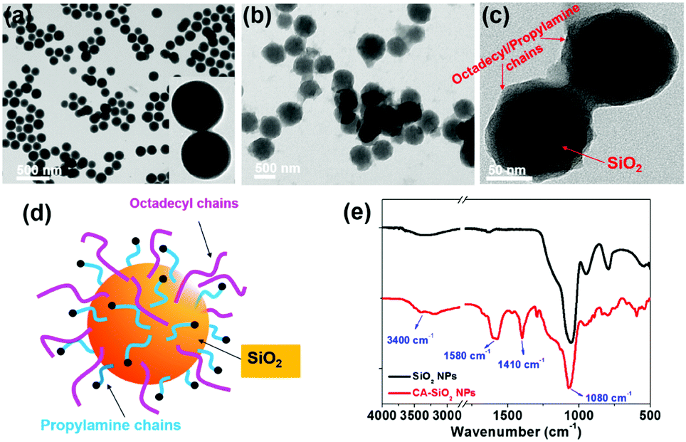 | ||
| Fig. 1 Morphologies and structures of octadecyl-/propylamine-capped silica (CA-SiO2) NPs. TEM images of pristine silica (a), octadecyl-/propylamine-capped silica NPs (b and c). (d) Schematic of the capped silica NPs. (e) FTIR spectra of the capped (bottom) and pristine (top) silica. | ||
Functionalized silica particles were further characterized by Fourier transform infrared (FTIR) spectroscopy and X-ray photoelectron spectroscopy (XPS). FTIR spectroscopy presented strong bands at 1100 cm−1 and 800 cm−1, which could be assigned to the asymmetric stretching vibration and symmetric stretching and deformation vibration of Si–O–Si (Fig. 1e). Several new peaks appear in the spectra of the functionalized silica, such as the symmetric and asymmetric stretching vibrations of –CH2– and –CH3 (2850 cm−1 and 2925 cm−1), the asymmetric deformation vibration of –CH3 (1410 cm−1) and the specific deformation vibration of NH2 (1560 cm−1). XPS studies confirm the chemical element composition of CA-SiO2 NPs (Fig. S1a, ESI†) by the emerging peak at 401.88 eV for the binding energy of N(1s). Thermogravimetric analysis yielded a quantitative organic content of about 16 wt% of CA-SiO2, close to the amount of silane (APTES and TMODS) added (Fig. S1b, ESI†). Thus, a core–shell structural schematic of the CA-SiO2 NPs is depicted in Fig. 1d, featuring the silica core capped with octadecyl and propylamine groups.
Generally, amino or carboxyl end groups coordinate precursors (Pb2+ and Cs+) to form nucleation points, at which the perovskite NCs grow.29,32 Herein, an in situ growing mechanism for the fabrication of nanocomposites by anchoring CsPbX3 spatially onto SiO2 particles is proposed in Fig. 2a. During the initial reaction system, nucleation can take place on the surface of the capped silica NPs. Then, the precursors will further attach onto the capped silica spheres surface over time, yielding CsPbBr3@CA-SiO2 composites with high luminescence.
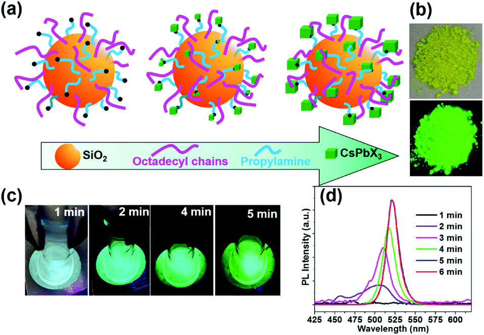 | ||
| Fig. 2 (a) Schematic of the synthesis of CsPbBr3@CA-SiO2. (b) Digital images of the composites under daylight and UV light. (c) Digital images of the reaction as a function of reaction time (0–5 min). (d) Photoluminescence spectra of the CsPbBr3@CA-SiO2 composites as a function of reaction time. | ||
As the reaction progresses, the transparent solution changes to glaucous and purple-blue emission under UV light, subsequently to blue and green (Fig. 2c). To gain insight into the reaction process, in situ PL spectra as a function of reaction time were measured with an interval of 1 min in Fig. 2d. Initially, no emission was detected. After 2 min, a weak and broad blue emission at 460–520 nm was observed, which was derived from the nucleation and preliminary growth of NCs. After 3 min and 5 min, cyan and bright green emission can be observed (Fig. 2d). With the prolongation of reaction time to 5 min, the PL spectra exhibited a continuous redshift, and the PL intensity increased gradually. PL studies indicated that the in situ growth can be quenched within 5 min in an ice bath. The dried powder of CsPbBr3@CA-SiO2 also exhibited strong luminescence under UV light, which can be used as high-performance solid-state emitters (Fig. 2b).
TEM show spherically shaped composites with fairly uniformly distributed NCs adhering to the surface of the silica sphere (Fig. 3a and b). No obvious large particles were observed. High-resolution TEM (HR-TEM) shows the crystallinity of CsPbBr3 NCs with an average size of 6 nm (Fig. 3c and d). The decorative perovskite NCs on SiO2 NPs surrounded with compact organic layers were notoriously sensitive to electron beam damage, so the HR-TEM images were taken quickly in order to minimize the exposure time.15,29 In comparison, SEM images of the blend of silica NPs and pre-obtained perovskite particles (to serve as a control) exhibited obvious phase separation with randomly distributed CA-SiO2 NPs and CsPbBr3 NCs (Fig. S4, ESI†).
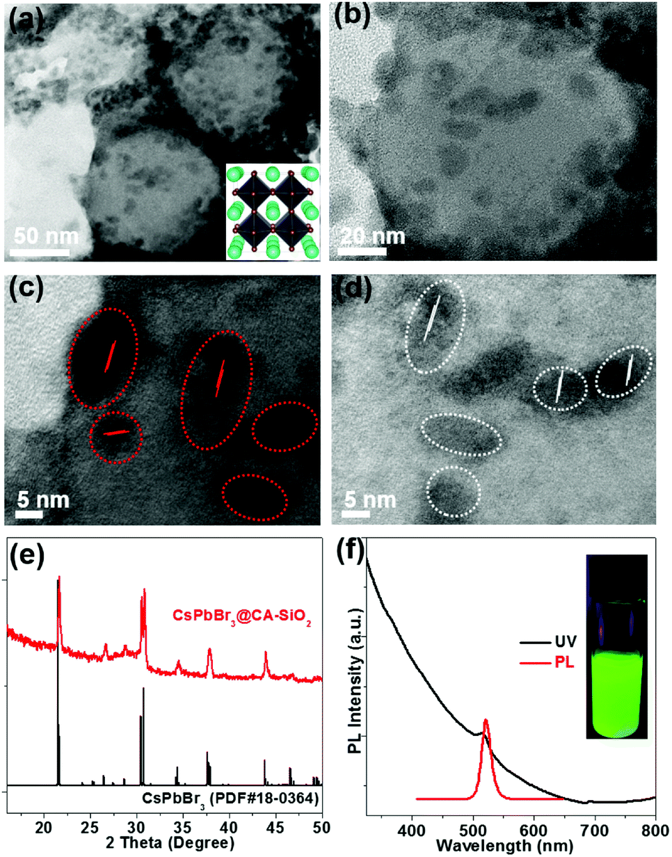 | ||
| Fig. 3 Morphologies, chemical structures and optical properties of the CsPbBr3@CA-SiO2 composite. TEM (a), high-magnification TEM (b) and high-resolution TEM (HR-TEM) images (c and d). The inset in (a) is a schematic of the crystal structure of CsPbBr3. (e) XRD pattern with the standard orthorhombic crystal structure of CsPbBr3. (f) Optical absorption and PL emission spectra. Inset in (f) is a photograph of the colloidal solution of the composites under UV light. | ||
The chemical structure of the CsPbBr3@CA-SiO2 composites was analyzed using powder X-ray diffraction pattern (XRD), XPS and energy dispersive spectrometer (SEM-EDS) analysis. Powder XRD of the CsPbBr3@CA-SiO2 yielded peaks at 2θ = 17.6°, 25.1°, 35.6°, 39.6°, 43.5°, 50.2°, 53.2° and 56.2° in the diffractogram, corresponding well to the orthorhombic CsPbBr3 crystal phase (JCPDF #01-072-7929) (Fig. 3e).1,2,28 XPS analyses (Fig. S5a, ESI†) further indicate that the elemental composition of the CsPbBr3@CA-SiO2 powder contained all the elements expected from CsPbBr3 NCs (Cs, Br and Pb) and capped SiO2 (Si, C, N and O). The elemental ratio of Cs![[thin space (1/6-em)]](https://www.rsc.org/images/entities/char_2009.gif) :Pb:Br measured by XPS was about 1:1.1:3.2, which was consistent with the expected ratio of CsPbBr3.28 SEM-EDS imaging further confirmed the presence of Si, Cs, Pb and Br in the CsPbBr3@CA-SiO2 composite (Fig. S5b, ESI†).
:Pb:Br measured by XPS was about 1:1.1:3.2, which was consistent with the expected ratio of CsPbBr3.28 SEM-EDS imaging further confirmed the presence of Si, Cs, Pb and Br in the CsPbBr3@CA-SiO2 composite (Fig. S5b, ESI†).
The UV-Vis absorption and photoluminescence (PL) spectra of the CsPbBr3@CA-SiO2 composite are shown in Fig. 3f. It was found that the absorption onset and PL emission peak of the CsPbBr3@CA-SiO2 composite were 518 nm and 520 nm, respectively (Fig. 3f), with a PLQY value of around 76%, higher than that of previously reported encapsulated NCs.34–36
By virtue of the facile synthetic process, we could also prepare CsPbBr3@A-SiO2 (CsPbBr3 NCs anchored on propylamine-capped silica NPs) and CsPbBr3@CC-SiO2 (CsPbBr3 NCs anchored on octadecyl-/carboxyl-capped silica NPs) composites. TEM analysis indicated the corresponding morphology in Fig. 4a and b. The anchored NCs distributed uniformly on the SiO2 particles, with average diameters between 6–14 nm. The crystallinity and elemental composition of CsPbBr3@A-SiO2 and CsPbBr3@CC-SiO2 were further confirmed by PXRD and XPS analyses (Fig. S6, ESI†). As expected, the CsPbBr3@A-SiO2 composite presented stronger PL emission than CsPbBr3@CC-SiO2 and similar PL emission to CsPbBr3@CA-SiO2 (Fig. 4c). Compared with CsPbBr3@CA-SiO2, the emission spectra of CsPbBr3@A-SiO2 and CsPbBr3@CC-SiO2 exhibited a slight red shift, with an emission maximum at 523 nm. A small shoulder at 495 nm can be detected for CsPbBr3@CC-SiO2, possibly attributable to the polar environment imposed by carboxylation.29
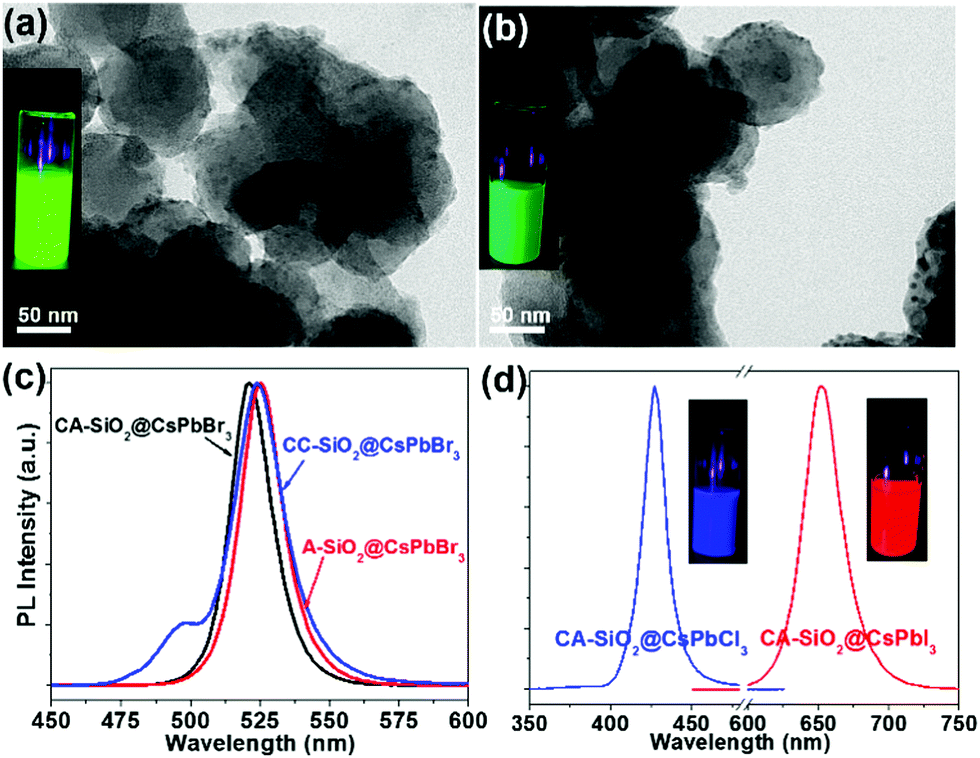 | ||
| Fig. 4 Morphology and optical properties of CsPbBr3@A-SiO2 and CsPbBr3@CC-SiO2 spheres. TEM images of typical CsPbBr3@A-SiO2 (a) and CsPbBr3@CC-SiO2 (b). Insets in (a) and (b) are photographs of the corresponding colloidal solutions under UV light. PL emission spectra of CsPbBr3@CA-SiO2, CsPbBr3@A-SiO2 and CsPbBr3@CC-SiO2 (c), and CsPbCl3@CA-SiO2 and CsPbI3@CA-SiO2 (d). | ||
It is worthwhile to mention that halide perovskites feature the flexible tunability of the bandgap through the modulation of the halide anion.2,3 We prepared CsPbX3@CA-SiO2 composites with various emission colors by using different lead halide precursors (from pure PbCl2 and PbI2 instead of PbBr2) in the nanocrystal synthesis. Fig. 4d shows the optical results of CsPbCl3@CA-SiO2 and CsPbI3@CA-SiO2. Compared with the pure bromide-based sample of green emission (520 nm), CsPbCl3@CA-SiO2 and CsPbI3@CA-SiO2 composites show blue (427 nm) and red (650 nm) emissive fluorescence, yielding PLQYs of 28% and 67%, respectively (Fig. 4d and Table S1, ESI†).
The thus formed CsPbBr3@CA-SiO2 composite was expected to provide excellent dewetting properties and enhanced photostability. The photostability of the CsPbBr3@CA-SiO2 composite was investigated by continuous illumination under UV lamps (365 nm). The CsPbBr3@CA-SiO2 composite presented outstanding photostability, with no measurable PL intensity decrease after 24 hours of constant illumination. Even after 100 h, ∼82% of the initial PL intensity was still maintained with no PL peak shift (Fig. 5c). In contrast, the pure CsPbBr3 film degraded from green to yellow upon illumination, and the PL intensity decreased dramatically over 24 h (Fig. 5c). Clearly, although there were no discrete barrier layers, the NCs on the CsPbBr3@CA-SiO2 composite were spatially isolated, which inhibited fusion, aggregation and other proximity-related degradation pathways.28,35,37
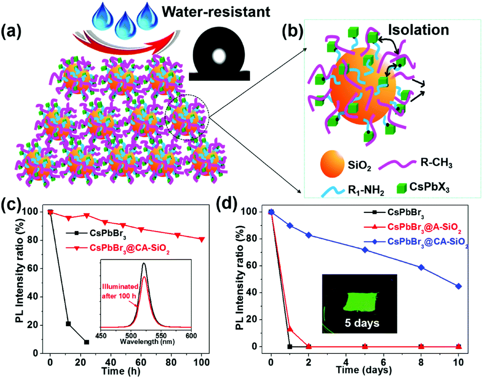 | ||
| Fig. 5 (a) Schematic of the film surface of CsPbBr3@CA-SiO2 composites with dewetting property. Inset in (a) is a photo showing the hydrophobicity of the WCAs. (b) Schematic of CsPbBr3@CA-SiO2. (c) The relative PLQY plots against different UV irradiation times. Inset in (c) is the PL intensity before and after illumination by UV light. (d) The relative PLQY plots of CsPbBr3, CsPbBr3@A-SiO2 and CsPbBr3@CA-SiO2 films upon immersion in water over time. Inset in (d) is a photograph of the CsPbBr3@CA-SiO2 film taken under UV irradiation after immersion in water for 5 days. | ||
To measure the water resistance of the composite, we immersed solid films on glass slides into deionized water (Fig. 5d). The relative PL of the CsPbBr3@A-SiO2 film decayed to 13% after 1 day and was fully quenched after 2 days. The pure perovskite films were completely quenched after 1 hour of water immersion. However, CsPbBr3@CA-SiO2 films presented much higher stability, retaining 72% and 59% PLQY after immersion in water for 5 days and 8 days, respectively (Fig. 5d). Besides, the surface was hydrophobic, as suggested by the static water contact angle of 132° (inset in Fig. 5a). The excellent dewetting property possibly resulted from the surface alkyl chains and micro/nano structural features (Fig. 5a), surpassing previously reported encapsulated NCs.32,38,39 Photographs inserted in Fig. 5d further confirm that the CsPbBr3@CA-SiO2 film remained highly fluorescent after immersion in water for 5 days. Compared with single SiO2 particle-coated CsPbX3 NCs that have exhibited enhanced stability,24,40 the in situ growth method to anchor the CsPbBr3 NCs onto amino-ligand functionalized SiO2 particles was superior in stabilizing the NCs by improving the spatial isolation of NCs and by providing an excellent dewetting barrier to shield environmental agents.
CsPbBr3@CA-SiO2 composite demonstrated excellent optical properties and high stability as the green fluorophore, which can be used as a proof of concept for multicolor anti-counterfeiting security ink. As a demonstration, Fig. 6a exhibited the customized patterns on a piece of filter paper under 365 nm UV light by CsPbCl3@CA-SiO2, CsPbBr3@CA-SiO2 and CsPbI3@CA-SiO2 composite inks with hand-carved seals, respectively. The ink was nearly colorless under room light, but exhibited excellent uniformity and strong PL emission under UV light, emitting bright red, green and blue colors (Fig. 6a). Besides, the high PL emission could be preserved even under immersion in water for 5 h, implying its excellent water stability (Fig. 6b), which was superior to other anti-counterfeiting security inks based on non-emissive Cs4PbX6 NCs.41
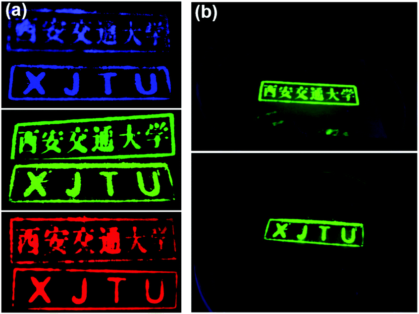 | ||
| Fig. 6 (a) Photograph of customized patterns containing CsPbCl3@CA-SiO2 (blue), CsPbBr3@CA-SiO2 (green) and CsPbI3@CA-SiO2 (red) under UV light. (b) Photograph of the patterns containing CsPbBr3@CA-SiO2 after immersion in water for 5 h. | ||
We also fabricated a down-converting white light emitting device (WLED).25,28,42Fig. 7a illustrates the typical WLED device structure, in which YAG powder and CsPbBr3@CA-SiO2 were used as the red and green sources. Each layer was sequentially deposited onto a blue-emitting GaN chip.28 The electroluminescence (EL) spectrum of the as-prepared WLED device presented a narrow green emission peak at 525 nm attributed to the CsPbBr3@CA-SiO2 and a broad red emission peak at 660 nm originating from the YAG phosphor, excited by the 460 nm GaN LED.
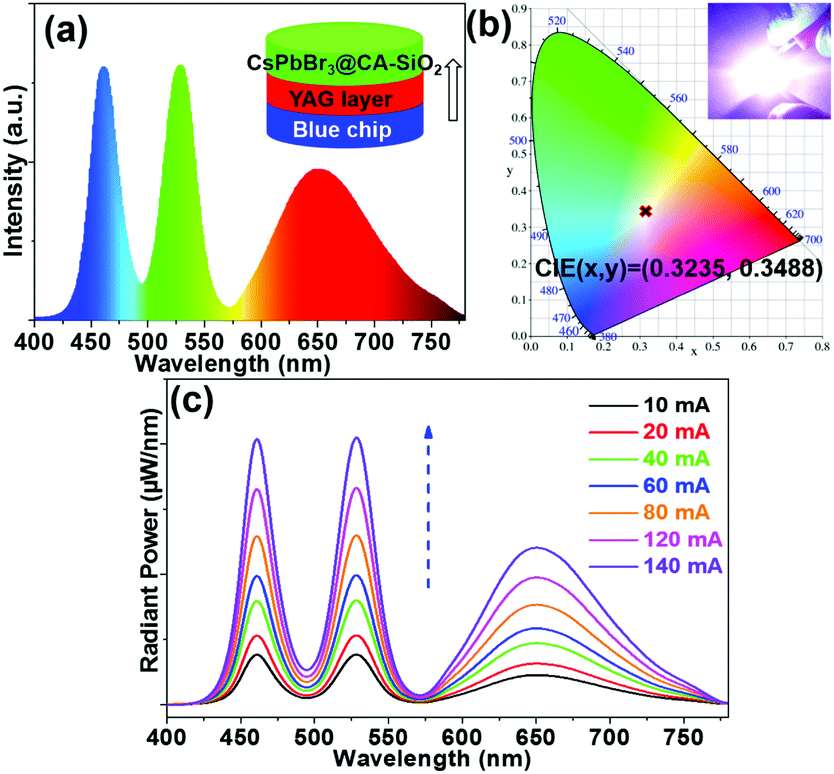 | ||
| Fig. 7 (a) EL emission spectra of the WLED. Inset in (a) is the schematics of the WLED, composed of GaN blue (460 nm) LED chips, CsPbBr3@CA-SiO2 films and YAG powder mixed with silicone resin as the blue, green and red light sources. (b) CIE color coordinates of the fabricated devices with composite films. Inset in (b) is a photograph of a working device with an applied current of 20 mA. (c) EL spectra of fabricated WLEDs under various operation currents. | ||
Saturated and bright white emission can be clearly observed when the device was operated at a current of 20 mA (Fig. 7b), featuring a CIE color coordinate (0.3225, 0.3468), very close to balanced white light emission (0.33, 0.33), indicating its high color purity. The WLED device exhibited an acceptable luminous efficacy (LE) of 26.3 lm W−1. The WLED device was highly stable at currents of up to 140 mA (Fig. 7c) and operated for 20 min at 20 mA (Fig. S7, ESI†), implying that the composite is a valuable light emitter even at high current densities. Therefore, these results indicate the great potential of the CsPbBr3@CA-SiO2 composite as a promising fluorophore for anti-counterfeiting and wide-color gamut lighting and display devices.
Conclusion
In summary, we report the facile synthesis of highly luminescent and stable CsPbX3@CA-SiO2 nanocomposites. The silica NPs capped with octadecyl and propylamine groups (approx. 120 nm) were employed as templates for perovskite NCs growth, yielding monodisperse NCs (∼6 nm) anchored onto SiO2 NPs. The resulting composites exhibited a high photoluminescence quantum yield (76%), tunable anion-dependent emission wavelength, enhanced photostability and remarkable water stability compared to the free NCs and previously reported encapsulated NCs. The CsPbX3@CA-SiO2 composite can be used as an anti-counterfeit ink and as a fluorophore for WLEDs, indicating their promising potential in solid-state optoelectronics. We believe this work will open the door for future research into multifunctional perovskite-based composites for real-world optoelectronic applications.Conflicts of interest
The authors declare no competing financial interest.Acknowledgements
This work was supported by the National Natural Science Foundation of China (NSFC Grants 51802254, 51873173), the China Postdoctoral Science Foundation Funded Project (2017M623149), the Fundamental Research Funds for the Central Universities (xjj2018053) and Shaanxi province Youth Foundation (2018JQ5011). Part of the work was also supported by the U.S. Department of Energy, Office of Science, Office of Basic Energy Sciences, Materials Sciences and Engineering Division, under Contract No. DE-AC02-05-CH11231 within the Inorganic/Organic Nanocomposites Program (KC3104) (MJ and YL). Work at the Molecular Foundry was supported by the Office of Science, Office of Basic Energy Sciences, of the U.S. Department of Energy under Contract No. DE-AC02-05CH11231. The authors wish to express their gratitude to the MOE Key Laboratory for Nonequilibrium Condensed Matter and Quantum Engineering of Xi’an Jiaotong University. The authors also thank Jiao Li at the Instrument Analysis Center of Xi’an Jiaotong University for their assistance with the TEM analysis.References
- L. Protesescu, S. Yakunin, M. I. Bodnarchuk, F. Krieg, R. Caputo, C. H. Hendon, R. X. Yang, A. Walsh and M. V. Kovalenko, Nano Lett., 2015, 15, 3692–3696 CrossRef CAS PubMed.
- G. Nedelcu, L. Protesescu, S. Yakunin, M. I. Bodnarchuk, M. J. Grotevent and M. V. Kovalenko, Nano Lett., 2015, 15, 5635–5640 CrossRef CAS PubMed.
- Q. A. Akkerman, V. D'Innocenzo, S. Accornero, A. Scarpellini, A. Petrozza, M. Prato and L. Manna, J. Am. Chem. Soc., 2015, 137, 10276–10281 CrossRef CAS PubMed.
- A. Swarnkar, R. Chulliyil, V. K. Ravi, M. Irfanullah, A. Chowdhury and A. Nag, Angew. Chem., Int. Ed., 2015, 54, 15424–15428 CrossRef CAS PubMed.
- V. Kovalenko, P. L. Maksym and M. I. Bodnarchuk, Science, 2017, 358, 745–750 CrossRef PubMed.
- S. A. Veldhuis, P. P. Boix, N. Yantara, M. Li, T. C. Sum, N. Mathews and S. G. Mhaisalkar, Adv. Mater., 2016, 28, 6804–6834 CrossRef CAS PubMed.
- S. Yakunin, L. Protesescu, F. Krieg, M. I. Bodnarchuk, G. Nedelcu, M. Humer, G. D. Luca, M. Fiebig, W. Heiss and M. V. Kovalenko, Nat. Commun., 2015, 6, 8056–8063 CrossRef CAS PubMed.
- Y. H. Kim, S. Kim, S. H. Jo and W. T. Lee, Small Methods, 2018, 1800093 CrossRef.
- H. Cho, Y. H. Kim, C. Wolf, H. D. Lee and T. W. Lee, Adv. Mater., 2018, 30, 1704587 CrossRef PubMed.
- T. Leijtens, G. E. Eperon, N. K. Noel, S. N. Habisreutinger, A. Petrozza and H. J. Snaith, Adv. Energy Mater., 2015, 5, 1500963 CrossRef.
- J. De Roo, M. Ibanez, P. Geiregat, G. Nedelcu, W. Walravens, J. Maes, J. C. Martins, I. Van Driessche, M. V. Kovalenko and Z. Hens, ACS Nano, 2016, 10, 2071–2081 CrossRef CAS PubMed.
- D. Parobek, Y. Dong, T. Qiao, D. Rossi and D. H. Son, J. Am. Chem. Soc., 2017, 139, 4358–4361 CrossRef CAS PubMed.
- Y. Kim, E. Yassitepe, O. Voznyy, R. Comin, G. Walters, X. Gong, P. Kanjanaboos, A. F. Nogueira and E. H. Sargent, ACS Appl. Mater. Interfaces, 2015, 7, 25007–25013 CrossRef CAS PubMed.
- S. Huang, Z. Li, B. Wang, N. Zhu, C. Zhang, L. Kong, Q. Zhang, A. Shan and L. Li, ACS Appl. Mater. Interfaces, 2017, 9, 7249–7258 CrossRef CAS PubMed.
- Z. Dang, J. Shamsi, F. Palazon, M. Imran, Q. A. Akkerman, S. Park, G. Bertoni, M. Prato, R. Brescia and L. Manna, ACS Nano, 2017, 11, 2124–2132 CrossRef CAS PubMed.
- J. Pan, L. N. Quan, Y. Zhao, W. Peng, B. Murali, S. P. Sarmah, M. Yuan, L. Sinatra, N. M. Alyami, J. Liu, E. Yassitepe, Z. Yang, O. Voznyy, R. Comin, M. N. Hedhili, O. F. Mohammed, Z. H. Lu, D. H. Kim, E. H. Sargent and O. M. Bakr, Adv. Mater., 2016, 28, 8718–8725 CrossRef CAS PubMed.
- B. Luo, Y. C. Pu, S. A. Lindley, Y. Yang, L. Lu, Y. Li, X. Li and J. Z. Zhang, Angew. Chem., Int. Ed., 2016, 55, 8864–8868 CrossRef CAS PubMed.
- A. Z. Pan, J. L. Wang, M. J. Jurow, M. J. Jia, Y. S. Wu, Y. Liu, Y. F. Zhang, L. He and Y. Liu, Chem. Mater., 2018, 30, 2771–2780 CrossRef CAS.
- H. Huang, B. Chen, Z. Wang, T. F. Hung, A. S. Susha, H. Zhong and A. L. Rogach, Chem. Sci., 2016, 7, 5699–5703 RSC.
- M. Imran, V. Caligiuri, M. Wang, L. Goldoni, M. Prato, R. Krahne, L. De Trizio and L. Manna, J. Am. Chem. Soc., 2018, 140, 2656–2664 CrossRef CAS PubMed.
- S. Zou, Y. Liu, J. Li, C. Liu, R. Feng, F. Jiang, Y. Li, J. Song, H. Zeng, M. Hong and X. Chen, J. Am. Chem. Soc., 2017, 139, 11443–11450 CrossRef CAS PubMed.
- Q. A. Akkerman, D. Meggiolaro, Z. Dang, F. De Angelis and L. Manna, ACS Energy Lett., 2017, 2, 2183–2186 CrossRef CAS PubMed.
- J.-Y. Sun, F. T. Rabouw, X.-F. Yang, X.-Y. Huang, X.-P. Jing, S. Ye and Q.-Y. Zhang, Adv. Funct. Mater., 2017, 27, 1704371 CrossRef.
- Q. Zhong, M. Cao, H. Hu, D. Yang, M. Chen, P. Li, L. Wu and Q. Zhang, ACS Nano, 2018, 12, 8579–8587 CrossRef CAS PubMed.
- C. Sun, Y. Zhang, C. Ruan, C. Yin, X. Wang, Y. Wang and W. W. Yu, Adv. Mater., 2016, 28, 10088–10094 CrossRef CAS PubMed.
- C. Zhang, B. Wang, W. Li, S. Huang, L. Kong, Z. Li and L. Li, Nat. Commun., 2017, 8, 1138 CrossRef PubMed.
- S. N. Raja, Y. Bekenstein, M. A. Koc, S. Fischer, D. Zhang, L. Lin, R. O. Ritchie, P. Yang and A. P. Alivisatos, ACS Appl. Mater. Interfaces, 2016, 8, 35523–35533 CrossRef CAS PubMed.
- A. Pan, J. Wang, M. J. Jurow, M. Jia, Y. Liu, Y. Wu, Y. Zhang, L. He and Y. Liu, Chem. Mater., 2018, 30, 2771–2780 CrossRef CAS.
- A. Pan, M. J. Jurow, F. Qiu, J. Yang, B. Ren, J. J. Urban, L. He and Y. Liu, Nano Lett., 2017, 17, 6759–6765 CrossRef CAS PubMed.
- Q. A. Akkerman, G. Raino, M. V. Kovalenko and L. Manna, Nat. Mater., 2018, 17, 394–405 CrossRef CAS PubMed.
- X. Li, Y. Wang, H. Sun and H. Zeng, Adv. Mater., 2017, 29, 1701185 CrossRef PubMed.
- W. Stöber, A. Fink and E. Bohn, J. Colloid Interface Sci., 1968, 26, 62–69 CrossRef.
- S. Hou, Y. Guo, Y. Tang and Q. Quan, ACS Appl. Mater. Interfaces, 2017, 9, 18417–18422 CrossRef CAS PubMed.
- D. Chen, S. Yuan, X. Chen, J. Li, Q. Mao, X. Li and J. Zhong, J. Mater. Chem. C, 2018, 6, 6832–6839 RSC.
- S. Yuan, D. Chen, X. Li, J. Zhong and X. Xu, ACS Appl. Mater. Interfaces, 2018, 10, 18918–18926 CrossRef CAS PubMed.
- S. Lou, T. Xuan, C. Yu, M. Cao, C. Xia, J. Wang and H. Li, J. Mater. Chem. C, 2017, 5, 7431–7435 RSC.
- A. Loiudice, S. Saris, E. Oveisi, D. T. L. Alexander and R. Buonsanti, Angew. Chem., Int. Ed. Engl., 2017, 56, 10696–10701 CrossRef CAS PubMed.
- T. Xuan, X. Yang, S. Lou, J. Huang, Y. Liu, J. Yu, H. Li, K. L. Wong, C. Wang and J. Wang, Nanoscale, 2017, 9, 15286–15290 RSC.
- J. Hai, H. Li, Y. Zhao, F. Chen, Y. Peng and B. Wang, Chem. Commun., 2017, 53, 5400–5403 RSC.
- H. Hu, L. Wu, Y. Tan, Q. Zhong, M. Chen, Y. Qiu, D. Yang, B. Sun, Q. Zhang and Y. Yin, J. Am. Chem. Soc., 2018, 140, 406–412 CrossRef CAS PubMed.
- X. Yu, L. Wu, H. Hu, M. Chen, Y. Tan, D. Yang, Q. Pan, Q. Zhong, T. Supasai and Q. Zhang, Langmuir, 2018, 34, 10363–10370 CrossRef CAS PubMed.
- T. Guner and M. M. Demir, Phys. Status Solidi A, 2018, 215, 1800120 CrossRef.
Footnote |
| † Electronic supplementary information (ESI) available. See DOI: 10.1039/c8qm00591e |
| This journal is © the Partner Organisations 2019 |