Gold nanoparticle layer: a versatile nanostructured platform for biomedical applications
Jingxian
Wu
,
Yangcui
Qu
,
Qian
Yu
 * and
Hong
Chen

State and Local Joint Engineering Laboratory for Novel Functional Polymeric Materials, College of Chemistry, Chemical Engineering and Materials Science, Soochow University, 199 Ren’ai Road, Suzhou 215123, People's Republic of China. E-mail: yuqian@suda.edu.cn
First published on 28th September 2018
Abstract
Gold nanoparticle layers (GNPLs) refer to a kind of nanostructured surfaces with immobilized gold nanoparticles (GNPs) at high density on a substrate. These materials not only exhibit excellent properties similar to those of free GNPs, such as good biocompatibility, large surface area, high electron transfer capability, unique photothermal properties, and convenient chemical and biological modification, but also have unique two-dimensional surface topography, making them suitable as nanostructured platforms. These properties account for the increasing applications of GNPLs in biology and medical science in recent years. In this review, we first briefly introduce several fabrication methods for GNPLs, including electrodeposition, chemical plating, spin coating, layer-by-layer deposition and patterned GNPLs. We then discuss biological applications of GNPLs, including in surface enhanced Raman scattering (SERS)- and enzyme linked immunosorbent assay (ELISA)-based bioassays, as electrodes modified with GNPLs for electrochemical biosensing, and as platforms for investigation of the interactions between cells and nanostructured surfaces. Surfaces with photothermal effects based on GNPLs for intracellular macromolecule delivery and antibacterial applications are also discussed. Finally, several challenges regarding research on GNPLs are presented, such as the development of fabrication methods that are capable of precisely controlling the hierarchical structure and further investigation of the influence of the roughness/topography on cellular behavior. It is our hope that through this review, researchers may gain a deeper understanding of GNPLs and become involved in their investigation.
1. Introduction
Nanomaterials, with structural features at the nanoscale, often have unique optical, electronic and mechanical properties, which are completely different from those of the corresponding bulk materials.1–3 The study of nanomaterials is a multidisciplinary field, including, but not limited to physics, chemistry, materials science and biology, and is of great interest in applications such as sensing, catalysis, anti-fouling and medical diagnosis.4–9 Among diverse kinds of nanomaterials, gold nanoparticles (GNPs) have been widely investigated. Their size- and shape-dependent optical and electronic properties, large surface-to-volume ratios, excellent biocompatibility, ease of modification with various functional groups (e.g. thiol and amino groups), and unique photothermal properties all contribute to their broad use in areas such as bio-sensing, disease diagnosis, intracellular detection and imaging, drug or gene delivery and photothermal cancer therapy.10–16 However, it should be noted that for most of these applications the GNPs are in the form of liquid suspensions, and as such have been reviewed extensively.17,18Gold nanoparticle layers (GNPLs), also referred to as gold nanoparticle arrays,19 gold nanoparticle thin films,20 or two-dimensional arrays of colloidal gold particles,21 are novel structured surfaces having nano or micro topography. Compared to liquid suspensions of GNPs, GNPLs, with numerous separated GNPs fixed and assembled on a substrate, not only have properties similar to those of suspended GNPs, but, in addition, have unique surface topography. Furthermore, the interactions between GNPs and the substrate and the synergetic effects between adjacent GNPs enhance their optical and electrical properties, all of which contribute to their increasing use in biology and medical science. For example, the high surface area, large loading capacity and high electron transfer efficiency of GNPLs are exploitable in biosensing technologies such as surface enhanced Raman scattering (SERS), enzyme linked immunosorbent assay (ELISA) and electrochemical biosensing; their controllable surface topography provides a suitable platform for the investigation of the influence of surface roughness on cellular behavior such as adhesion, proliferation and differentiation; and their strong photothermal effects causing membrane disruption of adherent cells can be used as the basis for intracellular macromolecule delivery systems and antibacterial coatings. In recent decades, we and other groups have become involved in this interesting topic and several intelligent designs have been developed. However, as far as we are aware, there has been no systematic review of recent developments on GNPLs for bio-applications.
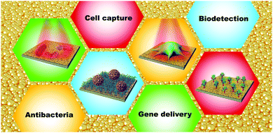
In this review, we first introduce several fabrication methods for GNPLs, including electrodeposition, chemical plating, spin coating, layer-by-layer deposition and patterned GNPLs. We then discuss several representative biomedical and biotechnology applications of GNPLs, including in SERS- and ELISA-based bioassays, in electrochemical biosensing, and as platforms for investigation of the interactions between cells and nano/micro-structured surfaces. Intracellular macromolecule delivery systems and antibacterial coatings based on the photothermal effect of GNPLs are also discussed (Scheme 1). We conclude with a brief discussion of potential developments of GNPLs for the future.
2. Fabrication and patterning of GNPLs
2.1 Fabrication of GNPLs
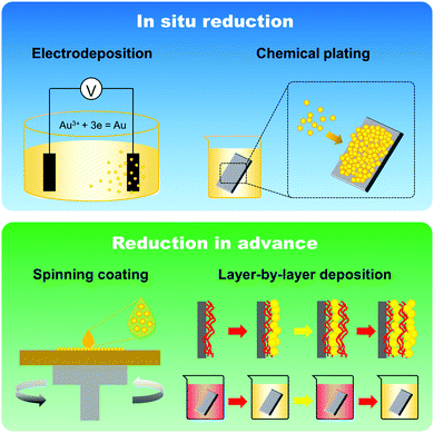
The fabrication of GNPLs, different from that of smooth gold surfaces prepared by metal evaporation or sputtering, is usually based on the reduction of hydrogen tetrachloroaurate hydrate (HAuCl4).22 In general, GNPLs can be fabricated either by in situ reduction of the HAuCl4 solution to deposit GNPs on substrates, or by self-assembly on substrates of GNPs synthesized in advance (Scheme 2).In situ reduction of the HAuCl4 solution usually involves immersing the substrate in a solution of HAuCl4. Reduction is then achieved in two ways: (i) via reduction–oxidation in an electrolytic cell formed by placing electrodes in the HAuCl4 solution as in electrodeposition;23 (ii) using chemical reducing agents such as sodium borohydride, glucose, chitosan, sodium citrate or sodium formate,24–26 as in chemical plating. Electrodeposition is usually employed to coat electrodes with GNPLs where the applied potential or the deposition time can be adjusted to control the size and morphology of the GNPL. However, electrodeposition can only be used with electrically conducting materials. With chemical plating, on the other hand, there are no restrictions on substrate properties such as conductivity, wettability or topography. Any flat substrate, such as polystyrene (PS) 96 well plates, glass slides, polymer films, gold slides or silicon slides can be coated with GNPLs: the process depends simply on gravitational sedimentation and aggregation of GNPs formed by the reduction of gold ions in the HAuCl4 solution (Fig. 1).26 In the chemical plating method, the surface roughness and porosity of the GNPL are adjustable by varying the volume of the plating solution, i.e. effectively varying the mole number of HAuCl4 in the plating solution. A larger volume of the plating solution will produce rougher GNPLs, and layers with roughness ranging from nanoscale to sub-microscale to microscale (100 nm–1 μm) can be fabricated.27
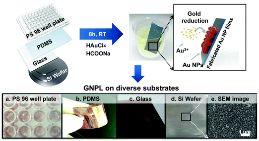 | ||
| Fig. 1 GNPLs fabricated on various substrates using the chemical plating method. Adapted with permission from ref. 26. | ||
In addition to the above mentioned in situ reduction of GNPs, GNPLs can also be fabricated by attaching pre-synthesized GNPs on substrates, either covalently or non-covalently.28 Using this method, the substrate is usually required to be pre-functionalized; the reactions between GNPs and thiol groups or cyano groups on the substrate are most frequently used for this purpose. Substrates functionalized with these groups can be coated with GNPs simply by immersing in a liquid suspension of the particles.29 This method is relatively simple compared to in situ reduction of GNPs; however, the topography and roughness of the GNPL are uncontrolled because of the random aggregation and distribution of GNPs on the substrate. Furthermore, large quantities of the GNP suspension are required, making this method unsuitable for large scale industrial production. Compared to simple immersion, spin coating after modifying the substrate with functional groups is more desirable because control of thickness and aggregate size distribution is possible.30 Other less commonly used methods such as electron irradiation31 and coordination reactions between bishydroxamic acid disulfide ligands and Zr4+ have also been reported.32
Broadly speaking, substrates modified with combinations of GNPs and other nanoparticles or materials could also be referred to as GNPLs; these are usually fabricated using layer by layer (LBL) assembly methods. In an LBL assembly, electrostatic attractions among multilayers are mostly utilized: alternating layers of oppositely charged polyelectrolytes are deposited onto the substrate, providing simple, controllable and versatile methods for surface modification and thin film fabrication.33,34 For the LBL assembly, GNPs need to be charged in advance. Unmodified GNPs are theoretically electrically neutral; however, they can be modified with charged reagents which render them stable in suspension. Different reducing agents employed in the synthesis process can produce GNPs with different charges. For example, sodium citrate and glucose produce negatively charged GNPs while hexadecyl trimethyl ammonium bromide generates positively charged GNPs. Sodium citrate is the most often used reducing agent for the production of negatively charged GNPs, and positively charged polyelectrolytes such as poly(allylamine hydrochloride) can be used with them in the fabrication of LBL-assembled GNPLs.35,36 GNPs can also become charged by forming positively charged dendrimer–gold nanoparticle complexes such as poly(amidoamine) dendrimers so as to form alternative layers with negatively charged poly(vinylsulfonic acid).37,38 Interactions between GNPs and molecules containing thiol groups can also be used to form LBL-assembled GNPLs.39 With disulfide-containing molecules such as 1,9-nonanedithiol as a spacer, GNPs can be self-assembled on the gold surface.40 Furthermore, covalently linked structures are more stable than electrostatically linked structures and the distance between two layers of GNPs is tunable by adjusting the length of the disulfide molecule. Compared to electrodeposition, chemical plating and spin coating, LBL technology can be used to fabricate GNPLs with precisely controlled thickness simply by adjusting the layer number. Moreover, additional functions can be introduced in some cases. For example, when negatively charged GNPs are assembled with alternating positively charged lysozyme, the resulting GNPLs are endowed with biocidal activity due to the antibacterial ability of lysozyme.36
In all of the above-mentioned fabrication methods, it should be noted that the aggregation of GNPs is unavoidable because the GNPs are assembled on the substrate in a disordered manner without any space restrictions. The distance between GNPs deposited on the substrate, therefore, is uncontrolled. Nevertheless, the particles should be more or less evenly distributed on the surface, and aggregation should be avoided in applications such as nanoelectronic circuitry and nanoscale sensor arrays where the GNPs’ distance-dependent optical and electronic properties will influence their functions.41,42 To prepare GNPLs with precisely controlled properties, a recent technique referred to as DNA templated self-assembly may be used.43 In this method, GNPs are conjugated with DNA to construct micrometer-scale objects with nanometer-scale feature resolution guided or directed by the complementary base pairing of base sequences in the DNA. Here, DNA is no longer considered as the carrier of genetic information but is used as the non-biological engineering building block.44,45 Factors contributing to the controlling effects of DNA templating are: (i) the geometry of DNA is well-defined and its intramolecular interactions are diverse while being programmable and highly predictable; (ii) DNA can be functionalized with various chemical groups that react with GNPs.46,47 In addition, DNA templated self-assembly is well-developed and is the method of choice for the construction of DNA lattices with well-defined patterns.44 The distance between GNPs can be precisely controlled by adjusting the periodicity and inter-particle spacing of the DNA scaffold.48 Methods for the conjugation of GNPs to DNA can be divided into three categories: (i) a single GNP is conjugated to several DNA oligomers. For example, Mirkin et al. modified GNPs with two different DNA oligomers, and a complementary DNA duplex was used to link the GNPs. However, nonspecific aggregation of GNPs occurred due to multiple DNA oligomers conjugating to GNPs.49 (ii) A single GNP is conjugated to a single DNA oligomer. In this case, nonspecific aggregation does not occur, but the DNA–GNP complexes are not stable at high salt concentration, especially in the presence of Mg2+, whereas stability under these conditions is a prerequisite for further DNA-templated self-assembly. Therefore, neither method (i) nor method (ii) is optimal.50 (iii) A combination of these two methods. For example, Yan et al. first conjugated DNA to GNPs using method (ii) and then “wrapped” the GNPs with unrelated DNA using method (i) to make the complex stable at high salt concentration (Fig. 2a).41 It should be noted that method (iii) is still under investigation and it cannot be used to fabricate GNPLs with desired patterns despite the fact that the interparticle spacing and hierarchical architectures of the GNPs could be precisely controlled. To make further improvement, DNA–GNPs were hybridized to a pre-assembled DNA scaffold with well-defined patterns and structures. Due to the specific complementary base pairing between pre-assembled DNA and DNA–GNPs, only desired areas would be modified with GNPs, generating thereby a well-defined DNA-templated self-assembled GNPL (Fig. 2b).51
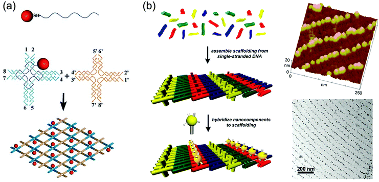 | ||
Fig. 2 Examples of GNPLs fabricated using DNA templated self-assembly. (a) Schematic illustration of fabrication of GNPLs using 1![[thin space (1/6-em)]](https://www.rsc.org/images/entities/char_2009.gif) : :![[thin space (1/6-em)]](https://www.rsc.org/images/entities/char_2009.gif) 1 conjugates of GNPs and thiolated DNA strands; (b) schematic illustration of fabrication of GNPLs with well-defined patterns and their typical AFM and TEM images. Adapted with permission from ref. 41 and 51, copyright 2006, Wiley-VCH Verlag GmbH & Co; copyright 2004, American Chemical Society. 1 conjugates of GNPs and thiolated DNA strands; (b) schematic illustration of fabrication of GNPLs with well-defined patterns and their typical AFM and TEM images. Adapted with permission from ref. 41 and 51, copyright 2006, Wiley-VCH Verlag GmbH & Co; copyright 2004, American Chemical Society. | ||
2.2 Patterning of GNPLs
For specific applications of GNPLs such as cell patterning and protein patterning, it is necessary to pattern the fabricated GNPL correspondingly. Patterning of GNPLs can be achieved either by depositing the GNPs exclusively in the area of interest in the process of fabrication,25 or by patterning the pre-fabricated GNPL using methods such as electro-corrosion.52Chemical plating and transfer printing are the two most commonly used methods to create patterned GNPLs during fabrication. The chemical plating method selectively deposits GNPs on substrates and confines the GNPs within specific areas. For example, specific areas of polydimethylsiloxane (PDMS) can be modified with the reducing agent chitosan, so that only the modified areas are deposited with GNPs.25 Alternatively, in transfer printing, a newly developed extension of micro-contact printing (μ-CP), both hard and soft materials can be modified.53 Transfer printing usually involves the transfer of the material from a stamp to a substrate “guided” by specific covalent interactions.54,55 For example, covalent interactions between GNPs and thiol groups may be used. When a thiol-modified substrate is contacted with a GNPL-coated patterning stamp, the interaction between the GNPs and thiol groups leads to transfer of GNPs from the stamp to the substrate (Fig. 3a).56 However, regardless of chitosan or thiol group modification, it is usually required that the substrate be pre-functionalized, and different modification methods are required for different substrates.
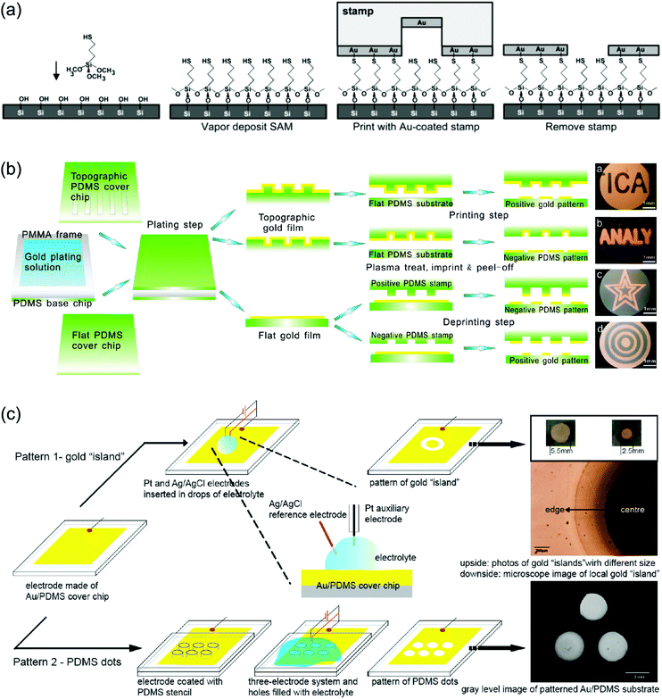 | ||
| Fig. 3 (a) Construction of patterned GNPLs by transfer printing using the covalent interactions between the GNPL and thiol groups; (b) construction of patterned GNPLs by air plasma assisted transfer printing; (c) construction of patterned GNPLs by electro-corrosion. The upper picture depicts the gold “island” formed by simply adding an electrochemical etchant onto the GNPL. The lower picture depicts PDMS dots formed using a PDMS stencil. The position of PDMS dots corresponds to the holes of the stencil. Adapted with permission from ref. 52, 56 and 57, copyright 2002, American Chemical Society; copyright 2010, American Chemical Society; copyright 2009, American Chemical Society. | ||
Alternatively, the GNPL on PDMS (stamp) could be transferred directly to a second piece of PDMS (substrate) using air plasma treatment, without the need for chemical functionalization. After treatment with air plasma, hydroxyl groups generated on the GNPL surface and Si–OH generated on the PDMS (substrate) interact rapidly over the contact area and thus the GNPL is transferred from the stamp PDMS to the substrate PDMS (Fig. 3b). The patterned GNPL-coated PDMS is then modified with cell adhesive peptides to promote cell adhesion on the modified areas and cell patterning is thereby achieved.57
Though extensively investigated, patterning of GNPLs during fabrication is relatively restricted, because it usually involves pre-treatment of the substrate. In addition, air plasma assisted transfer printing, as mentioned above, can only be applied to PDMS as a substrate. In contrast, patterning an existing GNPL by electro-corrosion is more widely applicable. In electro-corrosion, drops of an electrochemical etchant are first deposited on the GNPL. The GNPL, Ag/AgCl, and Pt wire function as the working electrode, the reference electrode and the auxiliary electrode respectively as illustrated in the magnified image of Fig. 3c. After application of a potential, the GNPL covered with electrolyte will be etched as an “island” pattern (the GNPL “island” is protected from electro-corrosion by the hydrogen bubble generated in water electrolysis) to expose the substrate, and therefore, forming a patterned GNPL surface. Alternatively, a pre-designed PDMS stencil can be placed on the GNPL before adding drops of an electrochemical etchant so that the etchant will fill the holes in the stencil and only naked GNPLs will be etched (Fig. 3c).52
3. Bio-applications of GNPLs
3.1 Biosensing
The unique optical and electrical properties of nanostructured surfaces make them strong candidates for biosensing.58,59 Biosensors with low detection limit and high sensitivity can be constructed using GNPLs with high surface plasmon resonance (SPR) responsiveness, high surface area, large loading capacity and high electron transfer efficiency. On the one hand, the high surface plasmon resonance responsiveness greatly enhances the local electromagnetic fields around GNPs60 and plays an important role in surface enhanced Raman scattering (SERS).61 On the other hand, the high surface area of GNPLs not only increases greatly the number of biomolecules that can be accommodated on the surface, but also leads to the formation of electrically conductive centers around the GNPs, which further facilitates the transfer of electrons. These properties make GNPLs a promising candidate for the construction of substrates in ELISA62 and electrodes in electrochemical biosensors.63 Details on recent examples of GNPLs in biosensing are reviewed in the following sections.In SERS, an analyte is first adsorbed on a rough substrate so that the chosen excitation frequency can excite a plasmon. As a substrate for SERS, a rough surface capable of immobilizing analytes and having strong localized surface plasmon resonance (LSPR) will be beneficial. Moreover, the substrate should be equipped with a regular distribution of hot spots where LSPR coupling produces a strong electric field. Because it directly relates to the reproducibility and uniformity of SERS, and the regular distribution of hot spots usually depends on the well-controlled topography and hierarchy structures of the substrate,67,68 therefore, the fabrication of reliable SERS substrates with rough surfaces, strong LSPR, well-controlled topography, high reproducibility and long term stability is central to the good performance of SERS measurements.69 GNPLs are rough surfaces, and present collective particle surface plasmon modes at wavelengths from 650 nm to 750 nm in the UV-Vis region, indicating that they are SERS active.70 Also amplified signals and enhanced electromagnetic fields can be achieved due to the high surface area of GNPLs and the interactions between separate localized surface plasmons in GNPLs, respectively.71 Furthermore, several fabrication methods, such as DNA-templated assembly and oil–water interfacial self-assembly of hydrophilic nanoparticles,72–74 have been optimized to prevent the random aggregation of GNPs, so that GNPLs with well-defined nanostructures can be obtained. As the most stable metal nanoparticles, GNPs are the ideal material to construct SERS substrates. The GNPL based SERS substrate has been utilized to detect amantadine,75 protein (BSA),76Salmonella typhimurium,77 penicillin G,78 and myoglobin79 with a low detection limit and high sensitivity.
The size, size distribution and shape of the separated GNPs are some factors that affect the sensitivity of SERS.80 The SERS signal increases with increasing GNP diameter (35 nm > 15 nm),81 and a narrow size distribution of GNPs leads to a sharp LSP resonance peak and an amplified signal. The shape of the GNPs also affects the SERS signal. For example, GNPLs composed of gold nanorods (NRs) (Fig. 4b) typically generate stronger SERS signals than nanosphere GNPLs (Fig. 4a). In SERS substrates, crevice areas form “hot spots” and generate the SERS signal.82 Contact between NRs is side-by-side, contributing to a larger crevice area than for NSs, whereas contact between the spheres is point-to-point; this may explain why the signal from NR GNPLs is stronger than that from NS layers. Furthermore, with increasing thickness of the GNPL, the SERS signal intensity increases almost linearly, presumably for the same reason (Fig. 4c).
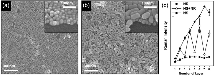 | ||
| Fig. 4 (a and b) Field emission scanning electron microscopy (FESEM) images of GNPs with different shapes: (a) nanospheres and (b) nanorods. (c) SERS signal intensity from GNPL substrates based on spheres and rods as a function of number of layers. Adapted with permission from ref. 83, copyright 2009, Elsevier B.V. | ||
GNPLs are rough surfaces with high surface area and micro-nanostructural features. These properties increase the loading capacity of proteins86 and alter the molecular conformation of the adhered proteins, due to the enlarged contact area and reduced steric hindrance on the 3D micro and nanostructured surfaces.87 Furthermore, based on the interactions between GNPs and amino groups in enzymes, enzymes can be immobilized on GNPL modified PS microtiter plates. This approach is much more convenient than the cumbersome pre-functionalization methods required for smooth PS microtiter plates. We have demonstrated that the quantities of lysozyme (LYZ), human serum albumin (HSA), and fibrinogen (Fg) adsorbed on GNPL-modified PS microtiter plates are 2.76, 2.34 and 3.26-fold higher than those on unmodified plates (Fig. 5a).62 The high electron transfer efficiency of GNPLs also boosts the sensitivity of ELISA. The sensitivity of GNPL modified PS microtiter plates was found to be 100-fold higher than that of unmodified plates in indirect ELISA: thus, quantities of CEA above 2 ng were enough to generate an effective ELISA signal (Fig. 5b).
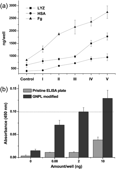 | ||
| Fig. 5 (a) Quantities of lysozyme (LYZ), human serum albumin (HSA) and fibrinogen (Fg) adsorbed on the GNPL-modified PS microtiter plate, I–V are GNPL modified plates with different roughness, the porosities of which are 66.3%, 55.2%, 47.0%, 38.1% and 33.8%, respectively. (b) Histogram of the indirect ELISA results. 100 μL human CEA solution (containing 0.08 ng, 2 ng and 10 ng CEA per well) in Tris buffered saline (TBS) (pH 7.4) was added to the pristine and GNPL-modified PS microtiter plate. Adapted with permission from ref. 62, copyright 2011, American Chemical Society. | ||
It should be noted that indirect ELISA is not suitable for complex samples such as plasma and serum containing multiple proteins because it cannot specifically bind with the target antigen, thus largely limiting its application in clinical diagnosis. Sandwich ELISA, with the detecting antibody immobilized on the substrate, is superior in this respect.85 GNPL modified PS microtiter plates showed good performance in sandwich ELISA as well (Fig. 6a). For IgG in a single protein solution, the detection limit of GNPL modified PS microtiter plates (0.0512 ng mL−1) was shown to be two orders of magnitude lower than that of unmodified plates (1.28 ng mL−1), and the detection limit for CEA in human plasma using the GNPL modified plate was found to be 2 ng mL−1, compared to 4 ng mL−1 for a typical commercial ELISA kit (Fig. 6b).88
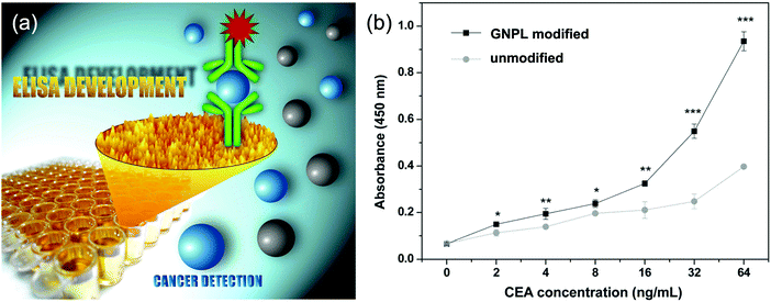 | ||
| Fig. 6 (a) Schematic illustration of the application of GNPLs in sandwich ELISA. (b) Performance of the GNPL-modified PS microtiter plate in sandwich ELISA for CEA in human plasma. Adapted with permission from ref. 88, copyright 2012, The Royal Society of Chemistry. | ||
Electrodes are usually modified with GNPLs using self-assembly of GNPs, electrodeposition or LBL methods.97 Compared to electro-deposited GNPLs and self-assembly of GNPs, multi-layered GNPLs formed using the LBL technique enhance electrode sensitivity to a greater extent because the signal increases (more or less linearly) with increasing number of GNPL layers.98,99 Various kinds of biomolecules can be detected by immobilizing enzymes or antigens on the GNPL-modified electrode surface. Examples included immobilization of apolipoprotein B for the detection of low-density lipoprotein,100 anti-human chorionic gonadotrophin to detect human chorionic gonadotrophin antigen,101 anti-CEA to detect CEA,98,102,103 horseradish peroxidase for hydrogen peroxide,104 glucose oxidase for glucose38,105–109 and acetylcholinesterase for acetylcholine.23 With greater biomolecule immobilization capacity, the sensitivity and limits of detection of sensors using GNPL modified electrodes are higher than those using unmodified electrodes.
3.2 Studies on cellular behaviors with GNPLs
Surface-adherent cells growing in a biological environment are affected not only by biological cues such as growth factors, hormones and small molecules in the culture medium, but also by the surface properties of the substrate such as its roughness and topography.110–112 Such effects are evident from the behavior of cells in the microenvironments of the body. Environments such as the extracellular matrix and the inner surface of blood vessels where cells reside consist of rough surfaces with specific topography at the nano and micro scales.113,114 Therefore, it is of great interest to study the influence of surface topography on cellular behavior on surfaces, and GNPLs provide a convenient platform for such studies.The surface roughness of GNPLs prepared using the chemical plating method can be controlled by adjusting the volume of plating solution used in the preparation; GNPLs with roughness ranging from 100 nm to 1 μm are readily fabricated.27 These layers can be used to explore the role of surface roughness on cell growth, including its effects on cell density and rate of proliferation. More specific phenomena such as the maintenance of stem cell pluripotency can also be explored. Furthermore, GNPLs modified with protein repelling polymers can be used to avoid the influence of adsorbed proteins on cell adhesion so that surface roughness effects are seen more clearly.
Stem cells, in contrast, behaved differently. The density of initially adhered cells was essentially independent of GNPL roughness: no obvious difference was observed in the numbers of adherent stem cells on GNPLs of different roughness (Fig. 7). However, in terms of the stem cell proliferation rate on days 3 and 7 of culture compared to that on day 1, it was found that GNPLs were more favorable than smooth gold. The highest relative proliferation rate on day 3, ≈1.3, was observed on the GL-1 material (Rq = 106 nm) while on smooth gold the rate was only 0.4; the difference was even greater on day 7.27 It may be concluded that although the rough surface of GNPLs decreases the initial adherence of stem cells, it provides a better substrate for their proliferation.
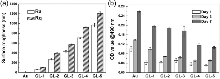 | ||
| Fig. 7 Adhesion and proliferation of stem cells on GNPLs of different roughness. (a) Surface roughness parameters Rq and Ra of the GNPL as measured via atomic force microscopy; (b) adhesion and growth of stem cells determined using an MTT assay. Adapted with permission from ref. 27, copyright 2014, The Royal Society of Chemistry. | ||
In addition to the effects of roughness on cell adhesion and proliferation as discussed, it has been reported that surface topographic features exert significant effects on the pluripotency of stem cells. The stemness of stem cells cultured on smooth gold and GNPLs with Rq < 392 nm was shown to be well maintained whereas on GNPLs with Rq > 573 nm cell stemness decreased even over the first three days of culture. This suggests that the roughness of the GNPLs accelerated spontaneous stem cell differentiation. Furthermore, it was found that stem cells tended to grow in larger colonies and to express E-cadherin and β-catenin (proteins that mediate cell–cell interactions) more extensively on smooth gold than on GNPL; this may explain the better maintenance of stemness on smooth gold (Fig. 8) because the close cell–cell interactions are favorable to the maintenance of cell pluripotency in the long term.27 Further studies on the influence of nano/micro topography on the differentiation of stem cells will be required to deepen our understanding of the behaviors of stem cells and may lead to advances in tissue engineering, gene therapy and other biomedical applications which depend on the use of stem cells.117,118
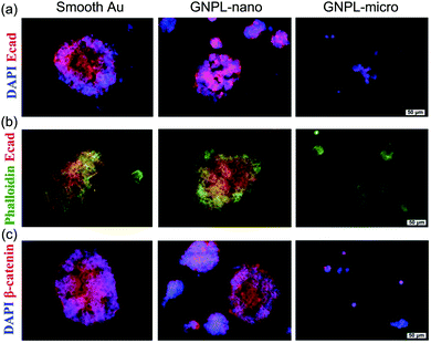 | ||
| Fig. 8 Immunofluorescence images of stem cells cultured on smooth gold and GNPLs of different roughness. GNPL-nano and GNPL-micro are GNPLs with nanoscale (Ra < 392 nm) and microscale (Ra > 573 nm) roughness, respectively. (a) Cells were co-stained for nuclei (DAPI, blue) and E-cadherin (red); (b) cells were co-stained for cytoskeleton (Phalloidin, green) and E-cadherin; (c) cells were co-stained for nuclei (DAPI, blue) and β-catenin (red). Adapted with permission from ref. 27, copyright 2014, The Royal Society of Chemistry. | ||
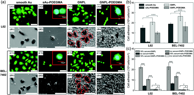 | ||
| Fig. 9 Cell adhesion and spreading on POEGMA modified protein resistant surfaces. (a) Typical confocal and SEM images of cells cultured on various surfaces; (b) cell adhesion on GNPL–POEGMA and Au–POEGMA; (c) cell adhesion on various surfaces in a serum free medium and in medium with 10% serum. Adapted with permission from ref. 120, copyright 2012, American Chemical Society. | ||
In addition to cell adhesion, cell spreading on protein-resistant POEGMA surfaces was also found to be affected by surface topography. Although cell spreading was somewhat constrained on POEGMA modified surfaces, cells on GNPL–POEGMA still showed small lamelipodia and short filopodia while cells on gold–POEGMA did not (Fig. 9a), indicating that “topographical” surfaces are more favorable for the firm attachment of cells than smooth surfaces.
The cells behaved differently when the protein repellent polymer modified GNPL was further decorated with bioactive molecules such as cell adhesive peptides or specific aptamers. For example, whereas the density of cells adherent on the GNPL surface decreased significantly when modified with POEGMA, adhesion increased dramatically on further modification with the cell binding RGD (arginine–glycine–aspartic acid) peptide, due presumably to the specific interactions between cell receptors and RGD. Adhesion on GNPL–POEGMA–RGD was not only much more than on GNPL and GNPL–POEGMA, but also more than on gold–RGD (Fig. 10a).116 The latter effect is perhaps due to the higher effective density of RGD peptides on the rough GNPL compared to the smooth gold surface.
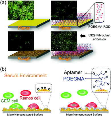 | ||
| Fig. 10 Cell interactions with GNPL surfaces modified with bioactive molecules. (a) L929 cells adherent on RGD modified GNPLs. (b) Capture and enrichment of Ramos cells with aptamer modified GNPLs. Adapted with the permission from ref. 116 and 123, copyright 2012, WILEY-VCH Verlag GmbH & Co.; copyright 2013, American Chemical Society. | ||
Specific interactions between cells and molecules immobilized on a surface can be exploited for the capture and enrichment of specific cell types, especially rare cells in the blood such as circulating tumor cells (CTCs) which are important in the early diagnosis of cancer.121,122 Aptamer-modified surfaces are often employed for the specific capture of cells, and based on this approach, the TDO5 aptamer (APT) with a high specific affinity for Ramos cells was employed to fabricate the GNPL–POEGMA–APT surface.123 Ramos cells and CEM cells were used as cell models to investigate the cell selectivity of GNPL–POEGMA–APT of different roughness (Fig. 10b). It was shown that with increasing roughness, Ramos cell adhesion increased significantly and was greater than CEM cell adhesion. Furthermore, POEGMA modification inhibited the nonspecific adsorption of proteins in the serum containing medium.
3.3 Applications of the photothermal effect of GNPLs
The photothermal effect is produced by photoexcitation, and results in the conversion of light (usually laser) energy to thermal energy.124 GNPs have a strong photothermal effect which can be achieved with unfocused laser light at low energy. GNP-mediated macromolecule delivery and antibacterial applications have been widely investigated.125–127 Under irradiation of appropriate energy, the heat generated by GNPs is sufficient to make cell membranes more permeable or disintegrate bacteria. Compared with dispersed GNPs, the GNPL with aggregated GNPs exhibits an enhanced photothermal effect due to the red-shifted absorption. Therefore, it is anticipated that the GNPL can be used as an efficient intracellular delivery system and an effective antibacterial material, which are elaborated below.Compared to carrier-based methods, membrane disruption-based intracellular delivery systems have fewer limitations on the type of target macromolecules that can be used.128 Membrane disruption generally involves the creation of small holes in the cell membrane, i.e., making the membrane more permeable by physical means such as microinjection, electroporation, laser optoporation, and the use of pore-forming agents. Any target molecule smaller than the holes in the cell membrane can be delivered to the cells. GNPLs, having a sufficient photothermal effect, are promising candidates for membrane disruption delivery systems. In particular, the GNPL with fixed GNPs can eliminate cytotoxicity brought about by a large number of GNPs entering the cells when using suspended GNPs as photoporation agents. When irradiated by near infrared laser light (e.g. wavelength 808 nm), GNPLs convert the laser energy into heat, thereby increasing the membrane permeability of cells in contact with the GNPL such that exogenous macromolecules can enter the cell. Based on this effect, a “universal” intracellular delivery system has been developed (Fig. 11a and b).130 As shown in five images taken from top to bottom of the cell membrane with the Z-stack mode of confocal microscopy (Fig. 11c), tetramethylrhodamine isothiocyanate (TRITC)-labeled dextran was present in the interior of the cells instead of merely attaching to the cell membrane. It was found that both dextran and plasmid DNA (pDNA) can be delivered with efficiency on the order of 100% into HeLa cells without compromising cell viability.
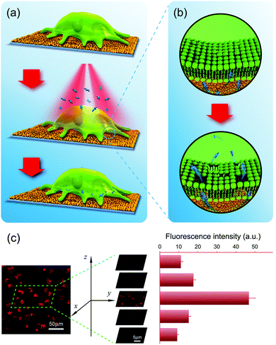 | ||
| Fig. 11 Intracellular delivery system based on the photothermal effect of GNPLs. (a) Schematic illustration of photoporation-based intracellular macromolecule delivery systems; (b) transient pores are created in the cell membrane upon laser irradiation, through which the macromolecules are delivered into the cells; (c) typical confocal microscope images showing the distribution of TRITC-dextran inside cells. Adapted with permission from ref. 130, copyright 2016, WILEY-VCH Verlag GmbH & Co. | ||
However, the transfection efficiencies of GNPL-based systems for recalcitrant cells (e.g. mouse embryonic fibroblasts (mEFs), 53%; human umbilical vein endothelial cells (HUVEC), 9%), though much higher than that of the widely used commercial transfection agent Lipofectamine 2000, are nonetheless insufficient. Most recalcitrant cells are hard to transfect because of their strong self-protective mechanisms and small size. For example, naked DNA delivered to the cytosol is easily degraded by enzymes. To further improve the transfection efficiency of such cells, the GNPL-based membrane disruption delivery was combined with low molecular weight polyethylenimine (LPEI) as a chemical carrier. Instead of naked pDNA, pDNA “wrapped” with LPEI was used to protect it from endonucleases.131 With this approach, transfection efficiencies for HUVEC and mEF of 94.6% and 88.5%, respectively, were achieved. Moreover, the functional pDNA, pZNF580, was successfully delivered to HUVECs for promotion of proliferation and migration. This approach may be useful in the development of tissue engineered vascular grafts.
Based on the photothermal effect of GNPLs, an efficient smart antibacterial hybrid coating with both photothermal bactericidal activity and bacteria-releasing properties was developed as illustrated in Fig. 12.144 This hybrid coating is composed of two functional layers, namely a GNPL and a thin phase-transitioned lysozyme film (PTLF) coated on the GNPL. Lysozyme undergoes a phase transition upon treatment with tris (2-carboxyethyl) phosphine, a disulfide bond breaker, forming a PTLF on the substrate. With densely aggregated oligomers in amyloid structures, the PTLF can bond to virtually any substrate.145,146 In particular, the PTLF will degrade by the treatment of vitamin C (Vc). In the present antibacterial systems, the GNPL serves as a bactericidal agent while the PTLF promotes the release of the dead bacteria by the treatment of Vc because the dead bacteria are removed as the PTLF layer is degraded.147,148 The upper layer of the PTLF has little influence on the light-to-heat conversion or the bactericidal efficacy of the GNPL because it is transparent. It was shown that more than 99% of attached Gram-positive S. aureus or Gram-negative E. coli were killed under near infrared laser radiation for 5 min. In addition, via degradation of the PTLF, virtually all of the dead bacteria were removed by treatment with Vc for 10 min. It should be pointed out that the thickness and extent of the PTLF that can be degraded is dependent on the concentration of Vc and the treatment time, and degradation takes place from the top PTLF layer. Therefore, dead bacteria will be released if the topmost PTLF degrades. It was found that at least three “kill-and-release” cycles could be realized with appropriate control of the degradation extent of the PTLF.
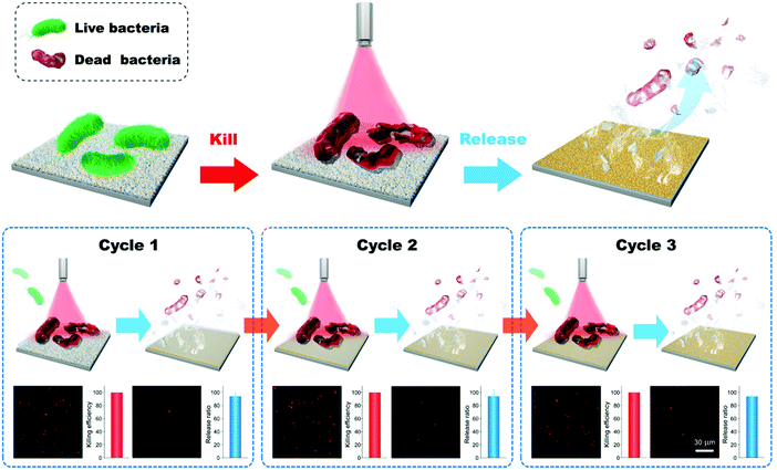 | ||
| Fig. 12 Smart antibacterial surfaces based on the photothermal effect of GNPLs and Vc-triggered degradation of the PTLF. Adapted with permission from ref. 144, copyright 2018, The Royal Society of Chemistry. | ||
4. Conclusions and perspectives
The past few decades have witnessed increasing awareness of the potential for biological applications of GNPLs, ranging from biosensors to the manipulation of cellular behavior. The reactions of gold with thiol, cyano, and amino groups make possible the modification of GNPLs using a variety of biomolecules. In addition, the variable and controllable surface topography of GNPLs can be exploited in the investigation of the influence of topography on cell growth. Despite recent advances, however, the potential of GNPLs has not yet been fully realized.Further research is required to address a number of challenges. A priority is to develop reliable methods to prepare GNPLs with controlled hierarchical structures. The DNA templated self-assembly method is promising but requires considerable additional development. Other fabrication methods such as chemical plating and LBL procedures need to be improved to allow control of the aggregation and distribution of GNPs on the substrate. Moreover, substrates with defined topography, as opposed to the flat, smooth materials currently used as substrates, should be further developed. Introducing the nano/micro structures of GNPLs to an already structured substrate may further increase the surface area in the layer and improve performance in biological applications.
The influence of the GNPL roughness/topography on cell growth also needs further investigation. What is currently known in this area is that different types of cells respond differently to surface roughness, but models that can predict behavior do not exist. It is clear that the mechanisms of cell adhesion and growth on materials in general depend on the interactions of related proteins, cell membrane receptors and the surface. Further research is required for a deeper understanding of cell behavior on surfaces in general and on topographical surfaces in particular.
Finally, it is noted that most of the applications of GNPL, such as the detection of cancer cells in the early diagnosis of tumors, and intracellular delivery systems based on the photothermal effects of GNPLs, are still under development though mainly at the fundamental level. We believe that more effort should be devoted in future to practical matters so that large scale exploitation becomes possible, and society can benefit from this technology. Thus, it is our hope that the intensity of research in this field will increase and that many more researchers will become involved in the near future.
Conflicts of interest
There are no conflicts to declare.Acknowledgements
This work was supported by the National Natural Science Foundation of China (21774086, 21674074, and 21334004), the National Key Research and Development Program of China (2016YFC1100402), the Natural Science Foundation of Jiangsu Province (BK20180093), and the Priority Academic Program Development of Jiangsu Higher Education Institutions (PAPD). The authors thank Prof. John L. Brash for helpful discussions.References
- K. Shehzad, Y. Xu, C. Gao and X. Duan, Chem. Soc. Rev., 2016, 45, 5541–5588 RSC.
- Y. Chen, Z. Fan, Z. Zhang, W. Niu, C. Li, N. Yang, B. Chen and H. Zhang, Chem. Rev., 2018, 118, 6409–6455 CrossRef CAS PubMed.
- D. Li, T. Liu, X. Yu, D. Wu and Z. Su, Polym. Chem., 2017, 8, 4309–4321 RSC.
- D. Quesada-Gonzalez and A. Merkoci, Chem. Soc. Rev., 2018, 47, 4697–4709 RSC.
- J. Mu, J. Lin, P. Huang and X. Chen, Chem. Soc. Rev., 2018, 47, 5554–5573 RSC.
- B. R. Smith and S. S. Gambhir, Chem. Rev., 2017, 117, 901–986 CrossRef CAS PubMed.
- E. K. Lim, T. Kim, S. Paik, S. Haam, Y. M. Huh and K. Lee, Chem. Rev., 2015, 115, 327–394 CrossRef CAS PubMed.
- G. Lazzari, P. Couvreur and S. Mura, Polym. Chem., 2017, 8, 4947–4969 RSC.
- D. A. Giljohann, D. S. Seferos, W. L. Daniel, M. D. Massich, P. C. Patel and C. A. Mirkin, Angew. Chem., Int. Ed. Engl., 2010, 49, 3280–3294 CrossRef CAS PubMed.
- N. N. M. Adnan, S. Ahmad, R. P. Kuchel and C. Boyer, Mater. Chem. Front., 2017, 1, 80–90 RSC.
- C. Matricardi, C. Hanske, J. L. Garcia-Pomar, J. Langer, A. Mihi and L. M. Liz-Marzan, ACS Nano, 2018, 12, 8531–8539 CrossRef CAS PubMed.
- D. Li, J. Wu, X. Liu, Y. Luan and H. Chen, Acta Polym. Sin., 2016, 7, 850–859 CrossRef.
- S. Delkhahi, M. Rahaie and F. Rahimi, J. Fluoresc., 2017, 27, 603–610 CrossRef CAS PubMed.
- S. Han, A. Samanta, X. Xie, L. Huang, J. Peng, S. J. Park, D. B. L. Teh, Y. Choi, Y. T. Chang, A. H. All, Y. Yang, B. Xing and X. Liu, Adv. Mater., 2017, 29, 1700244 CrossRef PubMed.
- J. Zhou, D. Wu, D. Lu and H. Duan, Acta Polym. Sin., 2018, 8, 1033–1047 Search PubMed.
- A. K. Rengan, A. B. Bukhari, A. Pradhan, R. Malhotra, R. Banerjee, R. Srivastava and A. De, Nano Lett., 2015, 15, 842–848 CrossRef CAS PubMed.
- K. Saha, S. S. Agasti, C. Kim, X. Li and V. M. Rotello, Chem. Rev., 2012, 112, 2739–2779 CrossRef CAS PubMed.
- E. Boisselier and D. Astruc, Chem. Soc. Rev., 2009, 38, 1759–1782 RSC.
- B. Auguie and W. L. Barnes, Phys. Rev. Lett., 2008, 101, 143902 CrossRef PubMed.
- T. Ung, L. M. Liz-Marzán and P. Mulvaney, Colloids Surf., A, 2002, 202, 119–126 CrossRef CAS.
- K. C. Grabar, K. J. Allison, B. E. Baker, R. M. Bright, K. R. Brown, R. G. Freeman, A. P. Fox, C. D. Keating, M. D. Musick and M. J. Natan, Langmuir, 1996, 12, 2353–2361 CrossRef CAS.
- D. Cassano, D. R. Martir, G. Signore, V. Piazza and V. Voliani, Chem. Commun., 2015, 51, 9939–9941 RSC.
- O. Shulga and J. R. Kirchhof, Electrochem. Commun., 2007, 9, 935–940 CrossRef CAS.
- X. Guo and N. Hu, J. Phys. Chem. C, 2009, 113, 9831–9837 CrossRef CAS.
- B. Wang, K. Chen, S. Jiang, F. Reincke, W. Tong, D. Wang and C. Gao, Biomacromolecules, 2006, 7, 1203–1209 CrossRef CAS PubMed.
- S. R. Ahmed, J. Kim, V. T. Tran, T. Suzuki, S. Neethirajan, J. Lee and E. Y. Park, Sci. Rep., 2017, 7, 44495 CrossRef CAS PubMed.
- Z. Lyu, H. Wang, Y. Wang, K. Ding, H. Liu, L. Yuan, X. Shi, M. Wang, Y. Wang and H. Chen, Nanoscale, 2014, 6, 6959–6969 RSC.
- S. Biswas, X. Liu, J. W. Jarrett, D. Brown, V. Pustovit, A. Urbas, K. L. Knappenberger Jr., P. F. Nealey and R. A. Vaia, Nano Lett., 2015, 15, 1836–1842 CrossRef CAS PubMed.
- Y. Jiang, P. Wan, M. Smet, Z. Wang and X. Zhang, Adv. Mater., 2008, 20, 1972–1977 CrossRef CAS.
- F.-K. Liu, Y.-C. Chang, F.-H. Ko, T.-C. Chu and B.-T. Dai, Microelectron. Eng., 2003, 67-68, 702–709 CrossRef CAS.
- Y. N. Kim, S. H. Yoo and S. O. Cho, J. Phys. Chem. C, 2009, 113, 618–623 CrossRef CAS.
- M. Wanunu, R. Popovitz-Biro, H. Cohen, A. Vaskevich and I. Rubinstein, J. Am. Chem. Soc., 2005, 127, 9207–9215 CrossRef CAS PubMed.
- J. J. Richardson, M. Bjornmalm and F. Caruso, Science, 2015, 348, aaa2491 CrossRef PubMed.
- F. X. Xiao, M. Pagliaro, Y. J. Xu and B. Liu, Chem. Soc. Rev., 2016, 45, 3088–3121 RSC.
- C. Jiang, S. Markutsya, H. Shulha and V. V. Tsukruk, Adv. Mater., 2005, 17, 1669–1673 CrossRef CAS.
- B. Zhou, Y. Li, H. Deng, Y. Hu and B. Li, Colloids Surf., B, 2014, 116, 432–438 CrossRef CAS PubMed.
- F. N. Crespilho, F. C. Nart, O. N. Oliveira and C. M. A. Brett, Electrochim. Acta, 2007, 52, 4649–4653 CrossRef CAS.
- F. N. Crespilho, M. E. Ghica, M. Florescu, F. C. Nart, O. N. Oliveira Jr. and C. M. A. Brett, Electrochem. Commun., 2006, 8, 1665–1670 CrossRef CAS.
- C. Xue, M. Gao, Y. Xue, L. Zhu, L. Dai, A. Urbas and Q. Li, J. Phys. Chem. C, 2014, 118, 15332–15338 CrossRef CAS.
- H.-L. Zhang, S. D. Evans and J. R. Henderson, Adv. Mater., 2003, 15, 531–534 CrossRef CAS.
- J. Sharma, R. Chhabra, Y. Liu, Y. Ke and H. Yan, Angew. Chem., Int. Ed. Engl., 2006, 45, 730–735 CrossRef CAS PubMed.
- S. Shiraishi, L. Yu, Y. Akiyama, G. Wang, T. Kikitsu, K. Miyamura, T. Takarada and M. Maeda, Adv. Mater. Interfaces, 2018, 5, 1800189 CrossRef.
- V. V. Thacker, L. O. Herrmann, D. O. Sigle, T. Zhang, T. Liedl, J. J. Baumberg and U. F. Keyser, Nat. Commun., 2014, 5, 3448 CrossRef PubMed.
- H. Yan, S. H. Park, G. Finkelstein, J. H. Reif and T. H. LaBean, Science, 2003, 301, 1882–1884 CrossRef CAS PubMed.
- Z. Li, J. Wang, Y. Li, X. Liu and Q. Yuan, Mater. Chem. Front., 2018, 2, 423–436 RSC.
- A. V. Pinheiro, D. Han, W. M. Shih and H. Yan, Nat. Nanotechnol., 2011, 6, 763–772 CrossRef CAS PubMed.
- M. R. Jones, K. D. Osberg, R. J. Macfarlane, M. R. Langille and C. A. Mirkin, Chem. Rev., 2011, 111, 3736–3827 CrossRef CAS PubMed.
- J. Sharma, R. Chhabra, Y. Liu, Y. Ke and H. Yan, Angew. Chem., Int. Ed. Engl., 2006, 118, 744–749 CrossRef.
- C. A. Mirkin, R. L. Letsinger, R. C. Mucic and J. J. Storhoff, Nature, 1996, 382, 607–609 CrossRef CAS PubMed.
- D. Zanchet, C. M. Micheel, W. J. Parak, D. Gerion and A. P. Alivisatos, Nano Lett., 2000, 1, 32–35 CrossRef.
- J. D. Le, Y. Pinto, N. C. Seeman, K. Musier-Forsyth, T. A. Taton and R. A. Kiehl, Nano Lett., 2004, 4, 2343–2347 CrossRef CAS.
- H. J. Bai, M. L. Shao, H. L. Gou, J. J. Xu and H. Y. Chen, Langmuir, 2009, 25, 10402–10407 CrossRef CAS PubMed.
- S. K. Abkenar, A. Tufani, G. O. Ince, H. Kurt, A. Turak and C. W. Ow-Yang, Nanoscale, 2017, 9, 2969–2973 RSC.
- M. K. Choi, I. Park, D. C. Kim, E. Joh, O. K. Park, J. Kim, M. Kim, C. Choi, J. Yang, K. W. Cho, J.-H. Hwang, J.-M. Nam, T. Hyeon, J. H. Kim and D.-H. Kim, Adv. Funct. Mater., 2015, 25, 7109–7118 CrossRef CAS.
- N. Kim, H. Kang, J. H. Lee, S. Kee, S. H. Lee and K. Lee, Adv. Mater., 2015, 27, 2317–2323 CrossRef CAS PubMed.
- Y.-L. Loo, R. L. Willett, K. W. Baldwin and J. A. Rogers, J. Am. Chem. Soc., 2002, 124, 7654–7655 CrossRef CAS PubMed.
- H. Gou, J. Xu, X. Xia and H. Chen, ACS Appl. Mater. Interfaces, 2010, 2, 1324–1330 CrossRef CAS PubMed.
- J. Tian, Z. Zhao, A. Kumar, R. I. Boughton and H. Liu, Chem. Soc. Rev., 2014, 43, 6920–6937 RSC.
- S. Zhang, R. Geryak, J. Geldmeier, S. Kim and V. V. Tsukruk, Chem. Rev., 2017, 117, 12942–13038 CrossRef CAS PubMed.
- L. A. Lyon, M. D. Musick, P. C. Smith, B. D. Reiss, D. J. Peña and M. J. Natan, Sens. Actuators, B, 1999, 54, 118–124 CrossRef.
- L. A. Lyon, D. J. Peña and M. J. Natan, J. Phys. Chem. B, 1999, 103, 5826–5831 CrossRef CAS.
- F. Zhou, L. Yuan, H. Wang, D. Li and H. Chen, Langmuir, 2011, 27, 2155–2158 CrossRef CAS PubMed.
- N. Xia, X. Wang, J. Yu, Y. Wu, S. Cheng, Y. Xing and L. Liu, Sens. Actuators, B, 2017, 239, 834–840 CrossRef CAS.
- T. Yaseen, H. Pu and D.-W. Sun, Trends Food Sci. Technol., 2018, 72, 162–174 CrossRef CAS.
- S. Schlucker, Angew. Chem., Int. Ed. Engl., 2014, 53, 4756–4795 CrossRef PubMed.
- J. Chen, L. Guo, B. Qiu, Z. Lin and T. Wang, Mater. Chem. Front., 2018, 2, 835–860 RSC.
- Q. Yu, H. Liu and H. Chen, J. Mater. Chem. B, 2014, 2, 7849–7860 RSC.
- M. F. Cardinal, E. V. Ende, R. A. Hackler, M. O. McAnally, P. C. Stair, G. C. Schatz and R. P. V. Duyne, Chem. Soc. Rev., 2017, 46, 3886–3903 RSC.
- Y. Huang, L. Dai, L. Song, L. Zhang, Y. Rong, J. Zhang, Z. Nie and T. Chen, ACS Appl. Mater. Interfaces, 2016, 8, 27949–27955 CrossRef CAS PubMed.
- K. C. Grabar, R. G. Freeman, M. B. Hommer and M. J. Natan, Anal. Chem., 1995, 67, 735–743 CrossRef CAS.
- Y. Chu, E. Schonbrun, T. Yang and K. B. Crozier, Appl. Phys. Lett., 2008, 93, 181108 CrossRef.
- S. Si, W. Liang, Y. Sun, J. Huang, W. Ma, Z. Liang, Q. Bao and L. Jiang, Adv. Funct. Mater., 2016, 26, 8137–8145 CrossRef CAS.
- Q. Guo, M. Xu, Y. Yuan, R. Gu and J. Yao, Langmuir, 2016, 32, 4530–4537 CrossRef CAS PubMed.
- G. Yang, L. Hu, T. D. Keiper, P. Xiong and D. T. Hallinan Jr., Langmuir, 2016, 32, 4022–4033 CrossRef CAS PubMed.
- M. Ma, J. Sun, Y. Chen, K. Wen, Z. Wang, J. Shen, S. Zhang, Y. Ke and Z. Wang, Food Chem. Toxicol., 2018, 118, 589–594 CrossRef CAS PubMed.
- A. Foti, C. D’Andrea, V. Villari, N. Micali, M. G. Donato, B. Fazio, O. M. Marago, R. Gillibert, M. Lamy de la Chapelle and P. G. Gucciardi, Materials, 2018, 11, 440 CrossRef PubMed.
- X. Ma, X. Xu, Y. Xia and Z. Wang, Food Control, 2018, 84, 232–237 CrossRef CAS.
- L. A. Wali, K. K. Hasan and A. M. Alwan, Spectrochim. Acta, Part A, 2018, 206, 31–36 CrossRef PubMed.
- M. Shorie, V. Kumar, H. Kaur, K. Singh, V. K. Tomer and P. Sabherwal, Microchim. Acta, 2018, 185, 158 CrossRef PubMed.
- M. Suzuki, Y. Niidome, Y. Kuwahara, N. Terasaki, K. Inoue and S. Yamada, J. Phys. Chem. B, 2004, 108, 11660–11665 CrossRef CAS.
- A. Wei, B. Kim, B. Sadtler and S. L. Tripp, ChemPhysChem, 2001, 12, 743–745 CrossRef.
- N. Félidj, J. Aubard, G. Lévi, J. R. Krenn, G. Schider, A. Leitner and F. R. Aussenegg, Phys. Rev. B: Condens. Matter Mater. Phys., 2002, 66, 245407 CrossRef.
- M. K. Oh, S. Yun, S. K. Kim and S. Park, Anal. Chim. Acta, 2009, 649, 111–116 CrossRef CAS PubMed.
- S. Zhang, A. Garcia-D’Angeli, J. P. Brennan and Q. Huo, Analyst, 2014, 139, 439–445 RSC.
- S. Y. Toh, M. Citartan, S. C. Gopinath and T. H. Tang, Biosens. Bioelectron., 2015, 64, 392–403 CrossRef CAS PubMed.
- J.-H. Lee, J. S. Kim, J.-S. Park, W. Lee, K. E. Lee, S.-S. Han, K. B. Lee and J. Lee, Adv. Funct. Mater., 2010, 20, 2004–2009 CrossRef CAS.
- F. Bellezza, A. Cipiciani and M. A. Quotadamo, Langmuir, 2005, 21, 11099–11104 CrossRef CAS PubMed.
- F. Zhou, M. Wang, L. Yuan, Z. Cheng, Z. Wu and H. Chen, Analyst, 2012, 137, 1779–1784 RSC.
- L. Wang, Q. Xiong, F. Xiao and H. Duan, Biosens. Bioelectron., 2017, 89, 136–151 CrossRef CAS PubMed.
- L. Rotariu, F. Lagarde, N. Jaffrezic-Renault and C. Bala, Trends Anal. Chem., 2016, 79, 80–87 CrossRef CAS.
- D. Grieshaber, R. MacKenzie, J. Vörös and E. Reimhult, Sensors, 2008, 8, 1400–1458 CrossRef CAS PubMed.
- Z. Wang and Z. Dai, Nanoscale, 2015, 7, 6420–6431 RSC.
- Y. Song, Y. Luo, C. Zhu, H. Li, D. Du and Y. Lin, Biosens. Bioelectron., 2016, 76, 195–212 CrossRef CAS PubMed.
- S. Guo and E. Wang, Anal. Chim. Acta, 2007, 598, 181–192 CrossRef CAS PubMed.
- X. Luo, A. Morrin, A. J. Killard and M. R. Smyth, Electroanalysis, 2006, 18, 319–326 CrossRef CAS.
- J. M. Pingarrón, P. Yáñez-Sedeño and A. González-Cortés, Electrochim. Acta, 2008, 53, 5848–5866 CrossRef.
- L. Lu, S. Wang and X. Lin, Anal. Chim. Acta, 2004, 519, 161–166 CrossRef CAS.
- B. Y. Wu, S. H. Hou, F. Yin, J. Li, Z. X. Zhao, J. D. Huang and Q. Chen, Biosens. Bioelectron., 2007, 22, 838–844 CrossRef CAS PubMed.
- B. Y. Wu, S. H. Hou, F. Yin, Z. X. Zhao, Y. Y. Wang, X. S. Wang and Q. Chen, Biosens. Bioelectron., 2007, 22, 2854–2860 CrossRef CAS PubMed.
- G. Jie, B. Liu, H. Pan, J. Zhu and H. Chen, Anal. Chem., 2007, 79, 5574–5581 CrossRef CAS PubMed.
- R. Chai, R. Yuan, Y. Chai, C. Ou, S. Cao and X. Li, Talanta, 2008, 74, 1330–1336 CrossRef CAS PubMed.
- X. Li, R. Yuan, Y. Chai, L. Zhang, Y. Zhuo and Y. Zhang, J. Biotechnol., 2006, 123, 356–366 CrossRef CAS PubMed.
- C.-Y. Tsai, T.-L. Chang, C.-C. Chen, F.-H. Ko and P.-H. Chen, Microelectron. Eng., 2005, 78-79, 546–555 CrossRef CAS.
- X. L. Luo, J. J. Xu, Q. Zhang, G. J. Yang and H. Y. Chen, Biosens. Bioelectron., 2005, 21, 190–196 CrossRef CAS PubMed.
- X. L. Luo, J. J. Xu, Y. Du and H. Y. Chen, Anal. Biochem., 2004, 334, 284–289 CrossRef CAS PubMed.
- Y. Du, X. L. Luo, J. J. Xu and H. Y. Chen, Bioelectrochemistry, 2007, 70, 342–347 CrossRef CAS PubMed.
- H. R. Cho, J. H. Lee, S. H. Cho and H. G. Ji, Bull. Korean Chem. Soc., 2016, 37, 401–403 CrossRef CAS.
- Y. Wang, W. Wei, X. Liu and X. Zeng, Mater. Sci. Eng., C, 2009, 29, 50–54 CrossRef CAS.
- M. Yang, F. Qu, Y. Li, Y. He, G. Shen and R. Yu, Biosens. Bioelectron., 2007, 23, 414–420 CrossRef CAS PubMed.
- G. Abagnale, M. Steger, V. H. Nguyen, N. Hersch, A. Sechi, S. Joussen, B. Denecke, R. Merkel, B. Hoffmann, A. Dreser, U. Schnakenberg, A. Gillner and W. Wagner, Biomaterials, 2015, 61, 316–326 CrossRef CAS PubMed.
- F. Robotti, S. Bottan, F. Fraschetti, A. Mallone, G. Pellegrini, N. Lindenblatt, C. Starck, V. Falk, D. Poulikakos and A. Ferrari, Sci. Rep., 2018, 8, 10887 CrossRef PubMed.
- Q. Yu, L. K. Ista, R. Gu, S. Zauscher and G. P. Lopez, Nanoscale, 2016, 8, 680–700 RSC.
- I. A. Janson and A. J. Putnam, J. Biomed. Mater. Res., Part A, 2015, 103, 1246–1258 CrossRef PubMed.
- B. M. Baker, B. Trappmann, W. Y. Wang, M. S. Sakar, I. L. Kim, V. B. Shenoy, J. A. Burdick and C. S. Chen, Nat. Mater., 2015, 14, 1262–1268 CrossRef CAS PubMed.
- A. C. De Luca, M. Zink, A. Weidt, S. G. Mayr and A. E. Markaki, J. Biomed. Mater. Res., Part A, 2015, 103, 2689–2700 CrossRef CAS PubMed.
- F. Zhou, D. Li, Z. Wu, B. Song, L. Yuan and H. Chen, Macromol. Biosci., 2012, 12, 1391–1400 CrossRef CAS PubMed.
- A. Trounson and N. D. DeWitt, Nat. Rev. Mol. Cell Biol., 2016, 17, 194–200 CrossRef CAS PubMed.
- R. Dai, Z. Wang, R. Samanipour, K. I. Koo and K. Kim, Stem Cells Int., 2016, 6737345 Search PubMed.
- X. Deng, N. M. Smeets, C. Sicard, J. Wang, J. D. Brennan, C. D. Filipe and T. Hoare, J. Am. Chem. Soc., 2014, 136, 12852–12855 CrossRef CAS PubMed.
- X. Shi, Y. Wang, D. Li, L. Yuan, F. Zhou, Y. Wang, B. Song, Z. Wu, H. Chen and J. L. Brash, Langmuir, 2012, 28, 17011–17018 CrossRef CAS PubMed.
- C. Alix-Panabieres and K. Pantel, Cancer Discovery, 2016, 6, 479–491 CrossRef CAS PubMed.
- Z. Wang, Y. Luan, T. Gan, X. Gong, H. Chen and T. Ngai, Colloids Surf., B, 2017, 150, 279–287 CrossRef CAS PubMed.
- Y. Wang, F. Zhou, X. Liu, L. Yuan, D. Li, Y. Wang and H. Chen, ACS Appl. Mater. Interfaces, 2013, 5, 3816–3823 CrossRef CAS PubMed.
- G. M. Neelgund and A. Oki, Mater. Chem. Front., 2018, 2, 64–75 RSC.
- R. Xiong, K. Raemdonck, K. Peynshaert, I. Lentacker, I. D. Cock, J. Demeester, S. C. D. Smedt, A. G. Skirtach and K. Braeckmans, ACS Nano, 2014, 8, 6288–6296 CrossRef CAS PubMed.
- Y. Feng, L. Liu, J. Zhang, H. Aslan and M. Dong, J. Mater. Chem. B, 2017, 5, 8631–8652 RSC.
- L. Mocan, F. A. Tabaran, T. Mocan, T. Pop, O. Mosteanu, L. Agoston-Coldea, C. T. Matea, D. Gonciar, C. Zdrehus and C. Iancu, Int. J. Nanomed., 2017, 12, 2255–2263 CrossRef CAS PubMed.
- M. P. Stewart, A. Sharei, X. Ding, G. Sahay, R. Langer and K. F. Jensen, Nature, 2016, 538, 183–192 CrossRef CAS PubMed.
- M. P. Stewart, R. Langer and K. F. Jensen, Chem. Rev., 2018, 118, 7409–7531 CrossRef CAS PubMed.
- Z. Lyu, F. Zhou, Q. Liu, H. Xue, Q. Yu and H. Chen, Adv. Funct. Mater., 2016, 26, 5787–5795 CrossRef CAS.
- J. Wu, H. Xue, Z. Lyu, Z. Li, Y. Qu, Y. Xu, L. Wang, Q. Yu and H. Chen, ACS Appl. Mater. Interfaces, 2017, 9, 21593–21598 CrossRef CAS PubMed.
- L. Hall-Stoodley, J. W. Costerton and P. Stoodley, Nat. Rev. Microbiol., 2004, 2, 95–108 CrossRef CAS PubMed.
- Q. Yu, Z. Wu and H. Chen, Acta Biomater., 2015, 16, 1–13 CrossRef CAS PubMed.
- S. H. Kim, E. B. Kang, C. J. Jeong, S. M. Sharker, I. In and S. Y. Park, ACS Appl. Mater. Interfaces, 2015, 7, 15600–15606 CrossRef CAS PubMed.
- Y. Shi, M. Liu, F. Deng, G. Zeng, Q. Wan, X. Zhang and Y. Wei, J. Mater. Chem. B, 2017, 5, 194–206 RSC.
- P. C. Ray, S. A. Khan, A. K. Singh, D. Senapati and Z. Fan, Chem. Soc. Rev., 2012, 41, 3193–3209 RSC.
- C. Burda, X. Chen, R. Narayanan and M. A. El-Sayed, Chem. Rev., 2005, 105, 1025–1102 CrossRef CAS PubMed.
- S. Eustisa and M. A. El-Sayed, Chem. Soc. Rev., 2006, 35, 209–217 RSC.
- T. Wei, Z. Tang, Q. Yu and H. Chen, ACS Appl. Mater. Interfaces, 2017, 9, 37511–37523 CrossRef CAS PubMed.
- T. Wei, W. Zhan, Q. Yu and H. Chen, ACS Appl. Mater. Interfaces, 2017, 9, 25767–25774 CrossRef CAS PubMed.
- T. Wei, W. Zhan, L. Cao, C. Hu, Y. Qu, Q. Yu and H. Chen, ACS Appl. Mater. Interfaces, 2016, 8, 30048–30057 CrossRef CAS PubMed.
- T. Wei, Q. Yu, W. Zhan and H. Chen, Adv. Healthcare Mater., 2016, 5, 449–456 CrossRef CAS PubMed.
- Q. Yu, J. Cho, P. Shivapooja, L. K. Ista and G. P. Lopez, ACS Appl. Mater. Interfaces, 2013, 5, 9295–9304 CrossRef CAS PubMed.
- Y. Qu, T. Wei, J. Zhao, S. Jiang, P. Yang, Q. Yu and H. Chen, J. Mater. Chem. B, 2018, 6, 3946–3955 RSC.
- D. Wang, Y. Ha, J. Gu, Q. Li, L. Zhang and P. Yang, Adv. Mater., 2016, 28, 7414–7423 CrossRef CAS PubMed.
- J. Gu, S. Miao, Z. Yan and P. Yang, Colloid Interface Sci. Commun., 2018, 22, 42–48 CrossRef CAS.
- W. Lee, I. Kim, S. W. Lee, H. Lee, G. Lee, S. Kim, S. W. Lee and D. S. Yoon, Macromol. Res., 2016, 24, 868–873 CrossRef CAS.
- J. Zhao, Y. Qu, H. Chen, R. Xu, Q. Yu and P. Yang, J. Mater. Chem. B, 2018, 6, 4645–4655 RSC.
| This journal is © the Partner Organisations 2018 |


