
 Open Access Article
 This Open Access Article is licensed under a Creative Commons Attribution-Non Commercial 3.0 Unported Licence
Redefining the roles of alkali activators for porous carbon†
Yonghui
Zhang‡
ab,
Xin
Xu‡
a,
Qingxuan
Geng‡
c,
Qingwei
Li
*c,
Xiuli
Li
a,
Yixuan
Wang
a,
Zihuan
Tang
a,
Biao
Gao
 a,
Xuming
Zhang
a,
Paul K.
Chu
d and
Kaifu
Huo
*ab
a,
Xuming
Zhang
a,
Paul K.
Chu
d and
Kaifu
Huo
*ab
aThe State Key Laboratory of Refractories and Metallurgy, Institute of Advanced Materials and Nanotechnology, Wuhan University of Science and Technology, Wuhan 430081, China
bWuhan National Laboratory for Optoelectronics (WNLO), School of Optical and Electronic Information, Huazhong University of Science and Technology, Wuhan 430074, China. E-mail: kfhuo@hust.edu.cn
cState Key Laboratory of Biobased Material and Green Papermaking, Advanced Research Institute for Multidisciplinary Science, Qilu University of Technology (Shandong Academy of Sciences), Daxue Road 3501, Jinan 250307, Shandong Province, China. E-mail: liqingwei@qlu.edu.cn
dDepartment of Physics, Department of Materials Science and Engineering, Department of Biomedical Engineering, City University of Hong Kong, Tat Chee Avenue, Kowloon 999077, Hong Kong, China
First published on 13th December 2024
Abstract
Alkali activation is a common method to prepare commercial porous carbon. In a mixed alkali activation system, the role of each individual alkali has generally been assumed to be the same as in a single alkali activation system, and the low corrosiveness of weak alkalis has mainly been emphasized. However, the intrinsic roles of the individual alkalis should be understood in detail and redefined to illuminate the activation pathways from the perspective of internal chemical reactions rather than corrosiveness. Herein, by combining in situ TG-MS analysis, DFT calculation and other characterizations, the activation processes were precisely tracked, and activation pathways were proposed. In the mixed alkali activation system, the strong alkali KOH served as the activation promoter, first decomposing into K2O, which then attacked the C–C bonds to form active reaction sites defined as pore seeds. The weak alkali K2CO3 acted as the activation pathway modifier; CO32− preferentially etched the pore seeds over K2O due to the lower reaction barrier of CO32− interacting with the pore seeds. Consequently, the rough etching reaction of KOH was replaced and suppressed by the gentler action of CO32−, forming more micropores. When the ratio of strong to weak alkali was 1![[thin space (1/6-em)]](https://www.rsc.org/images/entities/char_2009.gif) :1, the obtained CK1K2-122 exhibited the highest microporosity (82.61%) and a high specific surface area (1962.18 m2 g−1). It exhibited a high specific capacitance of 296.7 F g−1 and excellent cycling stability with 98.3% retention after 10000 cycles. The supercapacitor demonstrated a high energy density of 114.4 W h kg−1 at a power density of 17.5 kW kg−1, with a broad potential window of 3.5 V.
:1, the obtained CK1K2-122 exhibited the highest microporosity (82.61%) and a high specific surface area (1962.18 m2 g−1). It exhibited a high specific capacitance of 296.7 F g−1 and excellent cycling stability with 98.3% retention after 10000 cycles. The supercapacitor demonstrated a high energy density of 114.4 W h kg−1 at a power density of 17.5 kW kg−1, with a broad potential window of 3.5 V.
Introduction
Porous carbon has been extensively used in fields such as energy storage, catalysis, and adsorption and separation due to its high specific surface area (SSA), abundant pore structure, outstanding chemical stability and low cost.1–3 The well-defined pore structure of porous carbon is highly desirable for excellent performance, e.g., hierarchical porous carbon with a large number of micropores and appropriate mesopores and macropores is necessary for capacitive energy storage.4–6The structural features of porous carbon are highly dependent on the preparation strategy, and considerable efforts have been made to design and prepare porous carbon with diverse pore structures.7,8 To date, chemical activation with alkalis, such as KOH, NaOH, K2CO3, KHCO3 and their mixtures, remains the primary and most effective way to fabricate porous carbon.9–12 Among them, the strong alkali KOH is a traditional and highly representative chemical activator that was developed early on.13–15 Porous carbon prepared using KOH typically exhibits abundant pores and high specific surface area.16–18 After KOH, the weak alkali K2CO3, which is used as food additive and has lower corrosiveness, was introduced as an another alkaline activator to reduce or avoid the use of KOH due to the strong corrosiveness and equipment damage associated with KOH.19–22 Porous carbons can also be successfully prepared using K2CO3 as a single activator or as a co-activator with the strong alkali KOH.23 It is worth noting that when K2CO3 is used as a co-activator, the obtained porous carbons also have high specific surface areas and abundant pores comparable those achieved using to the activation effects of KOH alone.24–27 For example, porous carbon derived from bamboo using a mixture KOH and K2CO3 as the activator has a high specific surface area of 2417 m2 g−1. In short, porous carbon can be prepared via the alkali activation method, and the relationships between activation conditions and pore structures have been extensively studied.
Additionally, the activation mechanisms for single-activator systems using KOH or K2CO3 have been proposed, and the released gases during the activation process and the possible reaction processes have been investigated.28–34 However, in KOH and K2CO3 mixed alkali activation systems, the roles of KOH and K2CO3 have been considered to be roughly the same as in the single-activator KOH or K2CO3 systems, and K2CO3 has mostly been considered in general terms of weak alkalinity and low corrosiveness. The intrinsic chemical roles of KOH/K2CO3, their combined activation effect and the real activation pathway in mixed alkali systems have not been precisely studied and revealed, and the role of K2CO3 needs to be clarified from the perspective of chemical reactions rather than simply in terms of its corrosiveness. In situ tracking of the activation processes of different alkali activator systems at the chemical reaction level should be undertaken, and the results should be compared to redefine the roles of the alkalis and further clarify the chemical nature of combined strong and weak alkali activation.
Herein, commercial petroleum coke was used as the carbon precursor with pure KOH, K2CO3, and mixtures of KOH and K2CO3 as the activator, and different types of porous carbons were prepared. To reveal the activation pathways and redefine the roles of the alkalis, real-time tracking and detailed comparison of the intermediate products of the activation processes were conducted. The results indicated that in the mixed activator system, KOH acted as a promoter: KOH decomposed into K2O, which then attacked C–C bonds, resulting in the formation of numerous pore seeds. In the mixed system, K2CO3 acted as a pathway modifier: CO32− promoted a gentler reaction with numerous pore seeds to form porous carbon with ultra-high microporosity. By regulating the ratio of strong and weak alkalis, the optimized porous carbon CK1K2-122 exhibited the highest microporosity of 82.61%, a high specific surface area of 1962.18 m2 g−1 and excellent supercapacitive performance. This work provides new insights for the flexible design of activated carbons with tunable porous structures.
Results and discussion
General understanding of preparing porous carbon
As shown in Fig. 1, alkali activation is the primary and most common method to prepare commercial porous carbon. The strong alkali KOH is a traditional and highly representative chemical activator that was developed early on. Porous carbon prepared by KOH typically features high specific surface areas and abundant pores due to the strong activation ability of KOH. After KOH, the weak alkali K2CO3 with low corrosiveness was introduced into alkali activation systems to reduce or avoid the use of highly corrosive KOH. However, porous carbon prepared by activation with K2CO3 alone usually exhibits low specific surface area and poor porosity due to the weak activation ability of this weak alkali. Around the same time, KOH and K2CO3 mixed activation systems were developed, and their activation effects were found to be comparable to that of KOH alone. However, when K2CO3 was introduced, only its low corrosiveness was discussed; the source of the activation results in mixed activation systems was vaguely and generally assumed to be the balanced effect of alkaline strength. The real chemical roles of the individual alkalis and the chemical nature of their combined effect are still unclear, and the view of corrosiveness or alkalinity should be promoted. | ||
| Fig. 1 General schematic illustration of the preparation of activated porous carbons using KOH, K2CO3 and KOH + K2CO3 activation. | ||
Redefining roles of alkali for preparing porous carbon
To clarify the true chemical roles of the individual alkalis in the mixed activation system, the gases released from the different alkali systems were monitored in situ throughout the entire activation process using a mass spectrometer coupled to a thermogravimetry device (TG-MS); this in situ tracking method has also been used in other studies to investigate the pyrolysis mechanism.35,36 The TG and MS curves are shown in Fig. 2 and S1.† The activation processes can be divided into three stages: (i) stage I – pore seed formation; (ii) stage II – etching of pore seeds into pores; and (iii) stage III – continuous development of pores. The definition of pore seeds will be discussed in the subsequent section. As shown in Fig. 2b, the released gases were carefully monitored and compared, and the possible chemical reaction processes are summarized in Table 1. (i) From room temperature to 300 °C, in the KOH-only activation system, H2O (m/z = 18) and O2− (m/z = 16) were detected, and their MS curve shapes were almost the same, indicating that the OH− initially decomposed into H2O and O2−. Meanwhile, the release of CO (m/z = 28) was also detected, which indicated that the etching reaction had already started at this low temperature, with KOH beginning to react with the carbon petroleum coke. In contrast, in the K2CO3-only activation system, no CO was released at this stage. CO2 (m/z = 44) was also detected, and the MS curve shape of CO2 was consistent with that of O2−, indicating that CO32− underwent decomposition reaction to release CO2 and O2−, as shown in Table 1. In the KOH and K2CO3 mixed activation system, CO (m/z = 28) and O2− were also detected, and the temperature at which gas began to be released was the same as that of the KOH-only activation system, which also suggested that the etching reactions had already occurred in this system. At this low-temperature stage, the real pores cannot yet form. In the KOH-only activation system, CO was detected, and in the K2CO3-only activation system, no was CO released; thus, the release of CO (m/z = 28) is a signal that the etching reaction has already started between KOH and petroleum coke. This early etching reaction cannot produce actual pores and porous carbon but can generate active reaction sites for the subsequent formation of a large number of real pores; thus, these active reaction sites were defined as pore seeds. This can explain why most reported porous carbons and our carbons discussed in the following text obtained using activation involving KOH have a large specific surface area and abundant pore structure, whereas the porous carbons activated by K2CO3 alone usually have a smaller specific surface area.9,11,16,19,24,26 Therefore, the strong alkali KOH acted as an activation promoter. It can decompose into K2O, which can attack C–C bonds to release CO (Table 1) and form pore seeds for subsequent development into pores. Compared with activation using K2CO3 alone, in the mixed activation system, no CO2 was released, which indicated that the decomposition of K2CO3 was inhibited. Compared with KOH-only activation, the peaks of the H2O, O2− and CO molecules released in the mixed activation system shifted forward, and shape of the MS curve of CO was almost the same as that of O2− from this low temperature to 750 °C; however, this curve shape was obviously different from that in KOH-only activation. These results indicated that in the mixed activation system, the activation pathway was different than that in the KOH-only activation system, even though the released gas components were the same. Considering that the decomposition of K2CO3 was prevented, and the release trends of CO and O2− were consistent in the mixed activation system, we propose that the CO32− that was prevented from decomposing, can react with the carbon atoms from the pore seeds preferentially instead of K2O to release CO and O2−, as shown in Table 1. The reason that CO32− can react with the pore seeds preferentially over K2O is due to the lower reaction barrier for the combination of CO32− with carbon free radicals; this lower reaction barrier will be analyzed in detail later in the text. Therefore, the weak alkali K2CO3 acted as an activation pathway modifier; the strong etching reaction of KOH was suppressed, and CO32− promoted a gentler reaction with the pore seeds to form porous carbon with ultra-high microporosity. (ii) As the temperature rose from 300 °C to 700 °C, in the KOH activation system, K2O continuously and strongly attacked C–C bonds to produce carbon free radicals and could participate in a strong activation reaction with carbon free radicals, releasing CO (m/z = 28). Additionally, KOH can directly react with carbon free radicals, releasing H2 (m/z = 2). The pore seeds developed explosively to form larger pores rather than ultra-micropores. In the mixed KOH and K2CO3 systems, the strong etching reaction of KOH was continuously suppressed due to the lower barrier for the reaction of CO32− and carbon free radicals, and the pore seeds developed gently to form numerous ultra-micropores. In the pure K2CO3 system, in addition to the continuous decomposition of CO32− to produce CO2, only a small amount of K2O attacks C–C bonds to form a small number of pores. (iii) During the prolonged heating at 700 °C, the mixed KOH and K2CO3 system released a large amount of CO2 due to the decomposition of K2CO3. However, in the KOH-only system, the amount of CO2 released is lower due to the violent decomposition reaction at the early stage. | ||
| Fig. 2 Activation mechanism analysis. (a) TG profiles of KOH, K2CO3 and KOH + K2CO3 activation reactions. (b) MS curves of the gaseous activation products derived from the KOH, K2CO3 and KOH + K2CO3 activation processes tracked by TG-MS. | ||
| Stage | System | ||
|---|---|---|---|
| KOH | K2CO3 | KOH + K2CO3 | |
| Stage I 25–300 °C | 2OH− → H2O + O2− | CO32− → CO2 + O2− | 2OH− → H2O + O2− |
| KOH → K2O + H2O | H2O (bound) → H2O (g) | KOH → K2O + H2O | |

|
K+ intercalation compounds |

|
|
| K2O + C˙ → 2K + CO (strong) | C˙ + CO32− → 2CO + O2− (gentle and abundant) | ||
| Stage II 300–700 °C | K2O + C˙ → 2K + CO (strong) | CO32− → CO2 + O2− | C˙ + CO32− → 2CO + O2− (gentle and abundant) |
| 6KOH + 2C˙ → 2K + 3H2 + 2K2CO3 (strong and abundant) | K2CO3 → K2O + CO2 | 6KOH + 2C˙ → 2K + 3H2 + 2K2CO3 (strong but poor) | |

|
K+ catalysis | ||
| K+ catalysis | |||
| Stage III 700 °C maintenance | K2CO3 → K2O + CO2 | C˙ + CO32− → 2CO + O2− (gentle but very poor) | K2CO3 → K2O + CO2 |
To further reveal the reason why CO32− preferentially reacts with the pore seeds over K2O, thereby altering the activation pathway, we constructed molecular models of the K2O etching reactions both with and without the CO32− structure, and DFT calculations of the entire activation process were also carried out. The reaction of the activators with the petroleum coke will occur first on the surface/pores of the coke, and petroleum coke contains abundant aromatic structures. Therefore, a surface/pore model was constructed using a single aromatic structure in our calculation. Fig. 3a presents the detailed calculation of the reaction pathways without the involvement of CO32− in the activation. First, the oxygen atom of K2O attacks the C atom to form the C–O–K2 complex (KO1). Due to electron transfer and the close interaction of the electronegative O, the K–O bond is broken, and the ring closing reaction occurs to provide KO2 and KO3, respectively. As shown in Fig. 3c, this reaction requires more energy, resulting in a more vigorous etching reaction. Subsequently, the O atoms attack the aromatic group C to form pores, and a CO molecule is released. When CO32− is involved in the activation process, the reaction pathway and energy change tremendously. As shown in Fig. 3b, the ester group O on CO32− first attacks the carbon atom adjacent to K2O and forms a bond with K. Due to the high electronegativity of O, one O atom on CO32− could transfer to the secondary aromatic ring to form a C–O bond, and the remaining –CO2 group forms a C–C bond with the aromatic ring to give the complex KOC1. The carbon atom in the –O–C![[double bond, length as m-dash]](https://www.rsc.org/images/entities/char_e001.gif) O group in the KOC1 further reacts with the O atom, which the carbon atom in this group undergoes a cyclization reaction with the O on the secondary ring, and a carbonyl oxygen (O2−) is released to form the KOC2 complex. This step significantly reduces the energy required for etching. The O atom on the secondary aromatic ring carbon then undergoes a cyclization reaction with the C atom adjacent to K2O, and a CO molecule is released to form the complex KOC3. The O atom further attacks the adjacent carbon atom, another CO molecule is released, and the structure is changed from a six-membered ring to a five-membered ring to form the complex KOC4. Finally, breakage of the K–O bond and escape of another CO molecule occur to form KOC5. As can be seen from the free energy profiles in Fig. 3c, the activation path of K2O is simple, but it requires high energy and the activation reaction is violent. In the activation involving K2CO3, the barrier for the reaction of CO32− and the carbon free radical is much lower than that of K2O and the carbon free radical, which is beneficial for gentle activation reactions, and the activation path was changed due to the introduction of K2CO3. The key factor in this change in the reaction path is that the adjacent carbon atom of K2O in KOC3 is favorable for forming a five-membered ring with O, weakening the C–C bond. As depicted in Fig. S2 and S3,† comparing the strengths of bond 1, bond 2 and bond 3 in KO1 and KOC3, it is found that bond 1 and bond 2 of KOC3 exhibit weak bond energy. Therefore, it is more likely to be attacked by O to form a CO molecule.
O group in the KOC1 further reacts with the O atom, which the carbon atom in this group undergoes a cyclization reaction with the O on the secondary ring, and a carbonyl oxygen (O2−) is released to form the KOC2 complex. This step significantly reduces the energy required for etching. The O atom on the secondary aromatic ring carbon then undergoes a cyclization reaction with the C atom adjacent to K2O, and a CO molecule is released to form the complex KOC3. The O atom further attacks the adjacent carbon atom, another CO molecule is released, and the structure is changed from a six-membered ring to a five-membered ring to form the complex KOC4. Finally, breakage of the K–O bond and escape of another CO molecule occur to form KOC5. As can be seen from the free energy profiles in Fig. 3c, the activation path of K2O is simple, but it requires high energy and the activation reaction is violent. In the activation involving K2CO3, the barrier for the reaction of CO32− and the carbon free radical is much lower than that of K2O and the carbon free radical, which is beneficial for gentle activation reactions, and the activation path was changed due to the introduction of K2CO3. The key factor in this change in the reaction path is that the adjacent carbon atom of K2O in KOC3 is favorable for forming a five-membered ring with O, weakening the C–C bond. As depicted in Fig. S2 and S3,† comparing the strengths of bond 1, bond 2 and bond 3 in KO1 and KOC3, it is found that bond 1 and bond 2 of KOC3 exhibit weak bond energy. Therefore, it is more likely to be attacked by O to form a CO molecule.
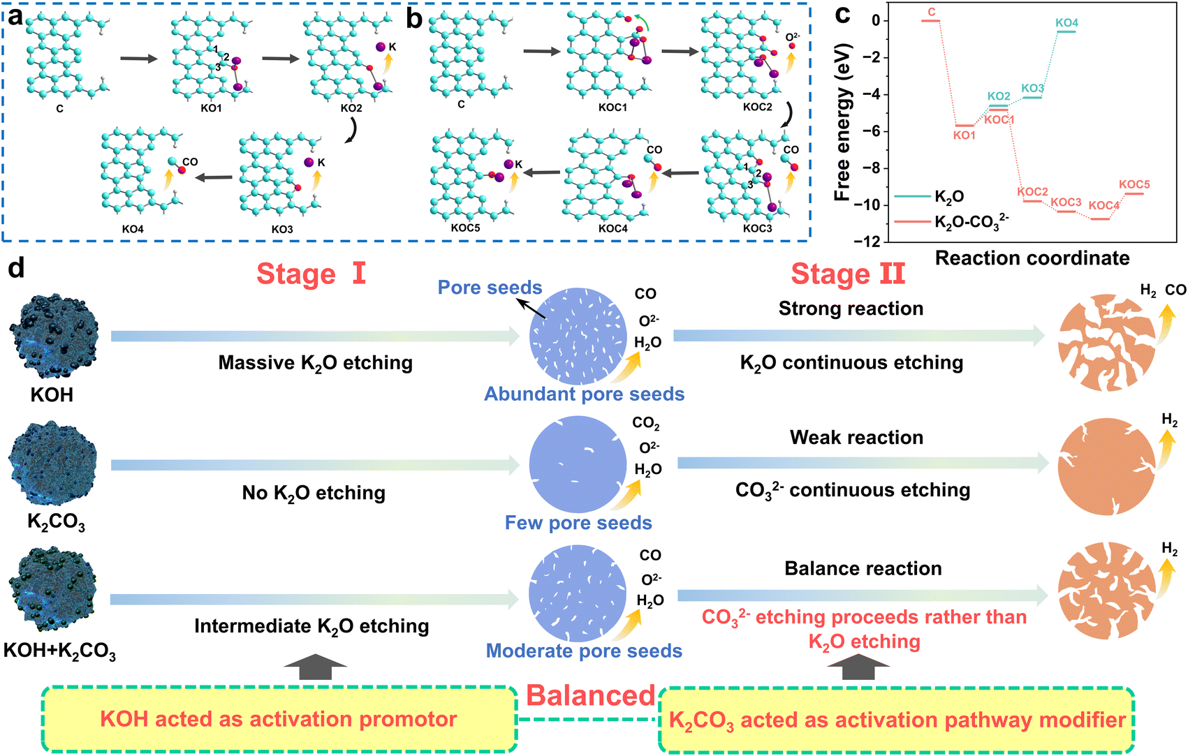 | ||
| Fig. 3 (a) Activation reactions for K2O model. (b) Activation reactions for the K2O–CO32− model. (c) Free energy profiles for the activation reactions of the K2O and K2O–CO32− models. (d) Schematic illustration of the real roles of the alkalis and the redefined activation pathway. | ||
In summary, Fig. 3d schematically illustrates the real roles of the alkalis in the KOH and K2CO3 mixed activation system. The strong alkali KOH acts as the activation promoter; it first decomposes into K2O, which can attack the C–C bond to form a large number of pore seeds. The pore seeds then develop into pores through subsequent etching reactions, but the development pathway differs for the different alkali activation systems. The weak alkali K2CO3 acted as an activation pathway modifier in the mixed alkali activation system. Compared to K2O, CO32− requires a lower reaction barrier to bind with carbon free radicals, and thus CO32− will preferentially react with carbon atoms in the pore seeds. Therefore, in the mixed alkali activation system, the strong etching reaction of KOH can be suppressed, and the reaction pathway changes from strong explosive etching by KOH to gentle etching by CO32−. The roles of KOH and K2CO3 in the mixed alkali activation system were redefined, and the vague concept of weak alkaline balanced activation was clarified from the perspective of the internal chemical reactions instead of simply in terms of corrosiveness and alkaline strength. The proposed activation mechanism will provide a foundation for regulating the pore structure in alkali activation.
Regulating pore structures and characterization of carbon
Based on the aforementioned perspective that the strong alkali KOH served as an activation promoter to produce pore seeds for the formation of abundant pores and the weak alkali K2CO3 acted as an activation pathway modifier to suppress the strong etching reaction of KOH and thus form more smaller micropores, we regulated the pore structure by adjusting the content of alkalis as described in the Experimental section. A porous carbon with ultra-high microporosity, large specific surface area and hierarchical pores was obtained for excellent capacitive energy storage by using a moderate ratio of strong to weak alkali. Fig. 4 presents the characterizations of the porous carbons prepared using several typical alkaline ratios. As shown in Fig. 4a, as the amount of K2CO3 was gradually decreased, the characteristic (002) peak at approximately 26° showed a decreasing trend;37 this peak nearly disappeared when KOH alone was used as the activator, indicating that the graphite microcrystalline structure of carbon had been completely corroded and destroyed by KOH, which led to poor electrical conductivity.38 The Raman spectra are shown in Fig. 4b; the G band peak intensity gradually decreased, and the defects increased with decreasing K2CO3. Thus, it is necessary to regulate the alkali content to control the etching degree and pathway to prepare porous carbon with the needed defects, microcrystalline structure and active sites. | ||
| Fig. 4 (a) XRD patterns and (b) Raman spectra of CK1K2-1x(4 − x) (x = 0, 1, 2, 3, 4). N2 adsorption–desorption isotherms of (c) CK1K2-1x(4 − x) (x = 0, 1, 2, 3, 4). Pore size distribution of (d) CK1K2-1x(4 − x) (x = 0, 1, 2, 3, 4). (e) Summary of the structure parameters of CK1K2-1x(4 − x) (x = 0, 1, 2, 3, 4). | ||
The specific surface area and pore size distribution are very important for capacitive energy storage performance. Generally, the pore size should be slightly larger than the electrolyte ion.39 The specific surface area, pore size distribution, structural parameters and relevant data are shown in Fig. 4c, d and Table S1.† The isotherms of CK1K2-1x(4 − x) (x = 0, 1, 2, 3, 4) were all type I; the adsorption and desorption curves were almost overlapped without obvious hysteresis loops, which verified that the petroleum-coke-derived porous carbon was dominated by micropores. From Table S1,† it can be seen that the specific surface area and pore volume showed a gradual decreasing trend with increasing the amount of potassium K2CO3. The micropore percentages of CK1K2-1x(4 − x) (x = 0, 1, 2, 3, 4) were 37.36%, 40.97%, 82.61%, 75.19% and 68.20%, respectively; CK1K2-122 has the largest microporosity and second-highest specific surface area of 1962.18 m2 g−1 (CK1K2-104: 600.56 m2 g−1; CK1K2-113: 880.33 m2 g−1; CK1K2-131: 1928.45 m2 g−1; CK1K2-140: 3373.79 m2 g−1). Different alkali ratios can lead to different pore size distributions; the pore size distributions are shown in Fig. 4d. In the KOH-only activation system, the pore seeds developed into 0.55 nm and 1.27 nm pores. Due to the strong etching reaction of KOH, the pore seeds tended to develop into larger micropores in the KOH-only activation system; compared with the other alkali ratio systems, the proportion of larger micropores (1.27 nm) in this system was higher. As the amount of K2CO3 was gradually increased, the strong etching reaction of KOH was inhibited, and the 1.27 nm micropores were first reduced first to 1.22 nm, then to 1.17 nm and finally disappeared. The microporosity of 0.55 nm gradually increased, and the microporosity of CK1K2-122 reached the maximum. This is attributed to the fact that K2CO3 acted as an activation pathway modifier that appropriately inhibited the strong etching reaction of KOH. In addition, in the K2CO3-only activation system, the few pore seeds could not develop into abundant pores. The temperature can affect the formation of pores; the specific surface area and pore size distribution of porous carbon obtained at different activation temperatures ranging from 600 °C to 800 °C are also shown in Fig. S4, S5 and Table S2.† It can be observed that as the activation temperature increased, the proportion of micropores increased, while the specific surface area and pore volume first increased and then decreased. It is worth noting that the size distribution of the micropores was always dominated at about 0.55 nm for the different activation temperatures and alkali ratios. The micropore pore size is perfectly matched to the solvated ion size,40 and the most effective ion adsorption is achieved by maximizing the available space (Fig. S6†), so excellent specific capacitance and energy density would be realized. CK1K2-122 has greatest microporosity and second-highest specific surface area, demonstrating that the moderate amount of KOH acted as an activation promoter to produce pore seeds for forming abundant pores, and the appropriate content of K2CO3 acted as an activation pathway modifier to suppress the strong etching reaction of KOH and thus form more smaller micropores. A sufficiently large micropore ratio and an ultra-high specific surface area are beneficial for adsorbing more electrolyte ions, so we believe that regulating the pore formation processes of stage I and stage II is essential to achieve porous carbon exhibiting high performance capacitor storage. In summary, an optimized porous carbon possessing the highest microporosity ratio, moderate pore volume and tap density and combining reasonable defects and conductivity can be prepared by carefully adjusting the alkali activator ratio and pathway (Fig. 4e and S7†).
Scanning electron microscopy (SEM) and transmission electron microscopy (TEM) were employed to characterize and analyze the micromorphology and graphite microcrystalline changes of the different samples. From Fig. S8,† it can be seen that the porous carbon gradually became fragmented with increasing KOH concentration;41 the block size of CK1K2-122 is intermediate. The TEM images are shown in Fig. S9.† Graphite microcrystallites are present in the CK1K2-104 sample, which may result from the catalytic effect of potassium; K2CO3 can be reduced into potassium vapor, and metal K can catalyze graphitization.42 The CK1K2-140 did not have an ordered structure due to the strong etching of KOH. The CK1K2-122 also exhibited some microcrystallites, indicating that K2CO3 inhibited the strong etching activation of KOH. The existence of microcrystallites is favorable for improving the conductivity.43–45 The presence of the elements C, O and N was determined for CK1K2-122 using energy dispersive spectroscopy (Fig. S10†). The uniform distribution of the elements O and N indicated that there were a large number of nitrogenous oxygen-containing functional groups in the porous carbon. The distribution of surface functional groups is conducive to the improvement of capacitance.
Electrochemical performance of porous carbon
The electrochemical performance of the CK1K2-1x(4 − x) (x = 0, 2, 4) was evaluated using a three-electrode system. The CV curves from −1 to 0 V are illustrated in Fig. 5a. Compared with CK1K2-104 and CK1K2-140, CK1K2-122 displayed the greatest integrated area and a quasi-rectangular shape at 20 mV s−1, indicating that it had the largest double-layer specific capacitance. The CV curves exhibited rectangle-like shapes at scan rates from 5 to 100 mV s−1, indicating excellent capacitive behavior and high reversibility (Fig. S11†). In addition, the GCD curve of CK1K2-122 in Fig. S12† exhibits an approximately symmetrical triangle, demonstrating good coulombic efficiency and the absence of a significant voltage drop.46 CK1K2-122 has a specific capacitance of 296.7 F g−1, which is about 1.5 times higher than that of CK1K2-104 (197.8 F g−1) and CK1K2-140 (197.3 F g−1) (Fig. 5b and S13†). The reason for this is that CK1K2-122 has the highest percentage of microporous pores, a high specific surface area, hierarchical pores, a reasonable pore size distribution, and good electrical conductivity. Electrochemical impedance tests were carried out, and the results are shown in Table S3.† The charge transfer resistance (Rct) and equivalent series resistance (Rs) of CK1K2-122 are slightly larger than those of CK1K2-104 (Fig. S14†), because more graphite microcrystals were produced in CK1K2-104 when K2CO3 alone was used as the activator. The slope of CK1K2-122 in the low-frequency region is almost parallel to the y-axis, which represents optimal fast transport characteristics. The cycling stability was tested at 20 A g−1, and the capacitance retention was 98.5% after 10000 cycles (Fig. 5c). This was attributed to the uniquely high microporosity, which mitigated the structural damage caused by volume shrinkage during the charging and discharging process.47 The b value of CK1K2-122 was calculated to be 0.903 (Fig. S15†), revealing the capacitive-dominated characteristics, as a b value close to 1 indicates electrochemical behavior dominated by surface pseudocapacitance control.48 As shown in Fig. S16,† the surface capacity control process accounts for 71%, 78%, 83%, 89% and 92% at 5, 10, 20, 50 and 100 mV s−1, respectively.
 | ||
| Fig. 5 Electrochemical properties: (a) CV curves of CK1K2-1x(4 − x) (x = 0, 2, 4) at 20 mV s−1. (b) Specific capacitance at different current densities. (c) Cycling stability of CK1K2-122 at 20 A g−1 (inset is GCD curves for first and last five cycles). Electrochemical performance of supercapacitor utilizing EMIMBF4 as the electrolyte: (d) schematic diagram of the supercapacitor. (e) Cycling stability at 20 A g−1 (inset is GCD curves for different current densities from 1–20 A g−1). (f) Ragone plots (inset is LED lights illuminated using supercapacitors as the power source). | ||
To further assess the electrochemical performance of the petroleum coke porous carbon CK1K2-122, a symmetrical supercapacitor was assembled using CK1K2-122 as the electrode and KOH as the electrolyte. Subsequent electrochemical tests were performed over a potential window of 0–1 V, as shown in Fig. S17.† The CV tests were conducted at scan rates from 10 to 100 mV s−1 (Fig. S18†) and showed rectangle-like shapes, and the GCD images showed symmetrical isosceles triangles; both these results indicated bilayer properties (Fig. S19†). The CK1K2-122 SCs showed a specific capacitance of 105.5 F g−1. After increasing the current 10 times, the capacity retention was 74%; the CK1K2-122 SCs displayed an excellent rate performance, as shown in Fig. S20.† The EIS diagrams exhibited a pronounced semicircle and a straight line nearly parallel to the y-axis (Fig. S21†). The equivalent series resistance (Rs) is 1.04 Ω, as displayed in Table S4,† which demonstrates the presence of a small charge transfer resistance and near-ideal capacitor behavior. It was determined that the supercapacitor achieved an energy density of 14.7 W h kg−1 at a power density of 500 W kg−1 when KOH is used as the electrolyte (Fig. S22†). The cycling stability of the aqueous supercapacitor was further evaluated at a current density of 20 A g−1, and a capacitance retention of 86.3% was observed after 10000 cycles (Fig. S23†).
To improve the practical applicability of the carbon materials, the organic system EMIMBF4 was used as the electrolyte to increase the voltage window to improve the energy density of supercapacitors. The model is depicted in Fig. 5d, and the GCD performance of the supercapacitor was evaluated using a potential window of 3.5 V. A capacitance retention of 72.9% was achieved after 8000 charge/discharge cycles at 20 A g−1 (Fig. 5e). The Ragone plot of the device clearly shows that the energy density reaches a maximum of 114.4 W h kg−1 at 1749 W kg−1 and 34.5 W h kg−1 at 17.5 kW kg−1 (Fig. 5f). To verify its performance in practical applications, it was used to power an LED light, which remained lit for 13 min until it was extinguished (inset and S24†). The energy density and power density compare favourably with those of other carbon-based materials (see Table S5† for details), such as HPCs (900 W kg−1, 107 W h kg−1),49 N, S–C (50 W kg−1, 9.75 W h kg−1),50 HPNC-NS (875 W kg−1, 102 W h kg−1),51 and 3DPAC (5100 W kg−1, 79.4 W h kg−1),52 among others. This high energy density and cycling stability demonstrate the potential of petroleum coke porous carbon materials in energy storage devices.
Conclusions
Various porous carbons were prepared using commercial petroleum coke as a carbon precursor and KOH, K2CO3, or mixtures of KOH and K2CO3 as an alkaline activator. Small molecules were monitored using in situ TG-MS to propose possible activation processes. The internal chemical reaction and pathway were further understood using DFT calculations and molecular simulations of the activation process. The strong alkali KOH acts as an activation initiator; it first decomposes into K2O to attack C–C bonds to form a large number of pore seeds. This is important for preparing porous carbon with a large number of pores and high specific surface area. The weak alkali K2CO3 acts as a modifier of the activation pathway; CO32− reacts with the carbon atom of the pore seeds more preferentially than K2O owing to the lower reaction energy barrier. This can suppress the strong etching reaction between K2O and the pore seeds to form porous carbon with high microporosity. By optimizing the ratio of strong and weak alkalis, the porous carbon CK1K2-122 was obtained; it exhibited an ultra-high microporosity of 82.61%, a high specific surface area of 1962.18 m2 g−1 and a hierarchical pore structure. It also showed a high specific capacitance of 296.7 F g−1 at 1 A g−1 and retained 98.5% of the initial capacity after 10000 cycles. The symmetric supercapacitor displayed an energy density of 114.4 W h kg−1 at a power density of 1749 W kg−1. After 8000 cycles at a current density of 20 A g−1, the capacity retention was 72.9%. This work offers a new perspective on the rational design of porous carbon materials for energy storage.
Experimental section
Materials and reagents
Potassium carbonate (K2CO3, AR, ≥99.0%), potassium hydroxide (KOH, AR, ≥99.0%), concentrated hydrochloric acid (HCl, 37%), ethyl alcohol (CH3CH2OH, AR, ≥99.7%), and 1-ethyl-3-methylimidazolium tetrafluoroborate (C6H11BF4N2, EMIMBF4) were bought from Aladdin Industrial Inc., Shanghai, China. All the chemicals were analytical reagents and were utilized directly without further purification. Petroleum coke was purchased from Shandong Lianhua New Material Co. The distilled water (DI) was prepared in the laboratory.Synthesis of porous carbon CK1K2-1x(4 − x) (x = 0, 1, 2, 3, 4)
The petroleum coke was pretreated before the experiment. It was broken up using a pulverizer, ball-milled (400 rpm, 2 h) and sieved (70 °C, 12 h) for the next step. The petroleum coke powder was ground and mixed with KOH and K2CO3 in a mass ratio of 1:2:2. The mixed samples were activated in a tube furnace under an N2 atmosphere with a rate of 100 mL min−1 at 700 °C for 5 h. After cooling to room temperature, the sample was washed with 1 M HCl at 80 °C for 5 h to remove excess K2CO3 and KOH. It was then ultrasonically rinsed to neutrality with deionized water, filtered and freeze-dried for 12 h. The resulting material was labeled as CK1K2-122. The C stands for petroleum coke, and K1 and K2 stand for KOH and K2CO3. For comparison, other mass ratios of petroleum coke, KOH and K2CO3 (1:0:4, 1:1:3, 1:3:1 and 1:4:0) were used, and the resulting samples were labeled as CK1K2-104, CK1K2-113, CK1K2-131 and CK1K2-140, respectively. The different temperatures used to prepare CK1K2-122 were 600 °C, 650 °C, 700 °C, 750 °C and 800 °C, and the samples were demoted as CK1K2-600, CK1K2-650, CK1K2-700, CK1K2-750 and CK1K2-800, respectively.
Materials characterization
To study the crystal structure and composition of the materials, their X-ray diffraction (XRD) patterns were obtained using an X-ray diffractometer instrument from 5°–90° at a scanning rate of 5 s per step. The X-ray photoelectron spectrum (XPS) was obtained using an X-ray photoelectron spectrometer (XPS, Escalab 210 system, Germany) to analyze the elemental composition of the samples. Scanning electron microscopy (SEM; Carl Zeiss-Ultra Plus, Germany) and transmission electron microscopy (TEM; FEI Tecnai G2F20, USA) were performed to investigate the morphological characteristics and the nanostructure of the materials. The Brunauer–Emmett–Teller (BET) specific surface areas and pore size distribution of the material were determined using N2 adsorption–desorption (Micromeritics ASAP 2020, USA). Thermogravimetric-mass analysis was performed using a Rigaku Thermo Mass Photo (TG-MS) with a skimmer type mass spectrometer (MS/EI). The measurements were conducted in the range 30–700 °C at 5 °C min−1. In addition, this measurement was carried out at 700 °C for 1 h. The whole experiment was carried out under an argon gas atmosphere.Computational details
All calculations were carried out based on density functional theory (DFT) as implemented in the Vienna ab initio simulation package (VASP) with exchange–correlation functional of the generalized gradient approximation (GGA) of Perdew, Burke, and Ernzerhof (PBE) method. A grid of 1 × 1 × 1 Monkhorst–Pack k-points was used for the structural relaxation. A vacuum layer of 15 Å was adopted in the direction perpendicular to the monolayer surface to avoid interactions between periodic slabs. The energy cutoff was set to 450 eV. The free energy changes were calculated according to the following equation:| ΔG = ΔE + ΔEZPE − TΔS |
Electrochemical measurements
The electrochemical properties of the material, including cyclic voltammetry (CV), galvanostatic charge–discharge (GCD), and electrochemical impedance spectroscopy (EIS) were all tested using an electrochemical workstation (CHI760E, Chenhua, Shanghai, China) with a three-electrode system composed of the active materials as the working electrode, a saturated calomel electrode as the reference electrode, and 1 × 1 cm2 Pt as the counter electrode in 6 M KOH electrolyte. The cycle stability evaluation was performed using a LAND CT2001A device from Wuhan, China. The CK1K2-122 electrode was obtained by mixing the active material, acetylene black and PTFE (6 wt%) in a mass ratio of 8:1:1 until a homogenous slurry was formed. The slurry was made into carbon flakes of about 1.5 mg and dried. The carbon flakes were coated onto nickel foam (1 cm × 1 cm) and pressed at 10–20 MPa to form a thin slice. Then, the performance of the three-electrode system was tested using a CHI760E instrument.
Data availability
All data have been provided in the main text and ESI.† We do not have additional data to provide.Author contributions
Yonghui Zhang, Xin Xu and Qingxuan Geng: conceptualization, methodology, formal analysis, writing – original draft. Qingwei Li: conceptualization, writing – review & editing. Xiuli Li: methodology. Yixuan Wang: validation, visualization. Zihuan Tang: validation, visualization. Biao Gao: conceptualization, supervision. Xuming Zhang: conceptualization, supervision. Paul K. Chu: conceptualization, administration. Kaifu Huo: conceptualization, writing – review & editing, supervision, project administration.Conflicts of interest
The authors declare no competing financial interest.Acknowledgements
This work was financially supported by the National Natural Science Foundation of China (U2004210, NSFC: 52003129), the National Key R&D Program of China (2022YFB2404800), the Basic Research Program of Shenzhen Municipal Science and Technology Innovation Committee (JCYJ20210324141613032), the City University of Hong Kong Strategic Research Grant (SRG 7005505), and the City University of Hong Kong Donation Research Grant (DON-RMG 9229021 and 9220061). Wuhan Baoju Carbon Material Limited Company (BGZ08022-04B). Basic Research Projects for the Pilot Project of Integrating Science and Education and Industry of Qilu University of Technology (Shandong Academy of Sciences) (2023PY029).Notes and references
- M. S. Md Zaini, M. Arshad and S. S. A. Syed-Hassan, J. Bioresour. Bioprod., 2023, 8, 66–77 CrossRef.
- X. Y. Liu, D. X. Lyu, C. Merlet, M. J. A. Leesmith, X. Hua, Z. Xu, C. Grey and A. C. Forse, Science, 2024, 384, 321–325 CrossRef CAS.
- J. Du, Q. H. Han, Y. Y. Chen, M. K. Peng, L. Xie and A. B. Chen, Angew. Chem., Int. Ed., 2024, e202411066 CAS.
- S. M. Chen, Z. P. Jia, M. J. Qiu, Y. C. Li, M. S. Ma and L. J. Liu, J. For. Eng., 2024, 9, 92–100 Search PubMed.
- J. X. Li, J. Kossmann, K. Zeng, K. Zhang, B. J. Wang, C. Weinberger, M. Antonietti, M. Odziomek and N. López-Salas, Angew. Chem., Int. Ed., 2023, 62, e202217808 CrossRef CAS PubMed.
- Z. Shang, X. Y. An, S. X. Nie, N. Li, H. B. Cao, Z. B. Cheng, H. B. Liu, Y. H. Ni and L. Q. Liu, J. Bioresour. Bioprod., 2023, 8, 292–305 CrossRef CAS.
- H. T. Jin, T. Y. Zhang, Z. W. Tian and S. H. Jiang, J. For. Eng., 2024, 9, 103–109 Search PubMed.
- F. Pan, K. Ni, T. Xu, H. C. Chen, Y. S. Wang, K. Gong, C. Liu, X. Li, M. L. Lin, S. Y. Li, X. Wang, W. S. Yan, W. Yin, P. H. Tan, L. T. Sun, D. P. Yu, R. S. Ruoff and Y. W. Zhu, Nature, 2023, 614, 95–101 CrossRef CAS PubMed.
- Z. Y. Pang, G. S. Li, X. L. Xiong, L. Ji, Q. Xu, X. L. Zou and X. G. Lu, J. Energy Chem., 2021, 61, 622–640 CrossRef CAS.
- J. Chmiola, G. Yushin, Y. Gogotsi, C. Portet, P. Simon and P. L. Taberna, Science, 2006, 313, 1756–1760 CrossRef.
- K. Wang and S. Xu, Processes, 2024, 12, 241 CrossRef CAS.
- G. Singh, A. M. Ruban, X. Geng and A. Vinu, Chem. Eng. J., 2023, 451, 139045 CrossRef CAS.
- J. Wang and S. Kaskel, J. Mater. Chem., 2012, 22, 23710–23725 RSC.
- L. H. Yan, A. J. Liu, R. Ma, C. Guo, X. H. Ding, P. Y. Feng, D. Z. Jia, M. J. Xu, L. L. Ai, N. N. Guo and L. X. Wang, Appl. Surf. Sci., 2023, 615, 156267 CrossRef CAS.
- T. Otowa, R. Tanibata and M. Itoh, Gas Sep. Purif., 1993, 7, 241–245 CrossRef CAS.
- P. Qin, C. Huang, B. Gao, C. R. Pi, J. J. Fu, X. M. Zhang, K. F. Huo and P. K. Chu, Appl. Surf. Sci., 2020, 503, 144293 CrossRef CAS.
- C. Liu, X. Z. Wu, L. Chen, Y. Li, X. Y. Wang, S. Y. Chen, Z. W. Fang, J. Zhou and S. P. Zhuo, J. Energy Storage, 2024, 91, 112024 CrossRef.
- R. L. Zornitta, K. M. Barcelos, F. G. E. Nogueira and L. A. M. Ruotolo, Carbon, 2020, 156, 346–358 CrossRef CAS.
- L. L. Duan, C. Y. Wang, W. Zhang, B. Ma, Y. H. Deng, W. Li and D. Y. Zhao, Chem. Rev., 2021, 121, 14349–14429 CrossRef CAS.
- Y. B. Xi, Y. Y. Wang, D. J. Yang, Z. K. Zhang, W. F. Liu, Q. Li and X. Q. Qiu, J. Alloys Compd., 2019, 785, 706–714 CrossRef CAS.
- Z. D. Liu, C. P. Duan, S. M. Dou, Q. Y. Yuan, J. Xu, W. D. Liu and Y. N. Chen, Small, 2022, 18, 2200954 CrossRef CAS.
- D. Lozano-Castello, M. A. Lillo-Rodenas, D. Cazorla-Amoros and A. Linares-Solano, Carbon, 2001, 39, 741–749 CrossRef CAS.
- X. H. Li, F. Sun, Z. B. Qu, Y. P. Feng, Y. Li, C. L. Yang, J. F. Li, W. S. Zhang, T. Wang and G. B. Zhao, Chem. Eng. J., 2024, 481, 148626 CrossRef CAS.
- I. Okman, S. Karagöz, T. Tay and M. Erdem, Appl. Surf. Sci., 2014, 293, 138–142 CrossRef CAS.
- X. Jin, Z. M. Yu and Y. U. Wu, Cellul. Chem. Technol., 2012, 46, 79–85 CAS.
- Y. T. Li, Y. T. Pi, L. M. Lu, S. H. Xu and T. Z. Ren, J. Power Sources, 2015, 299, 519–528 CrossRef CAS.
- K. X. Li, W. Chen, H. P. Yang, Y. Q. Chen, S. W. Xia, M. W. Xia, X. Tu and H. P. Chen, Bioresour. Technol., 2019, 280, 260–268 CrossRef CAS PubMed.
- L. J. Wang, F. Sun, F. Hao, Z. B. Qu, J. H. Gao, M. J. Liu, K. F. Wang, G. B. Zhao and Y. K. Qin, Chem. Eng. J., 2020, 383, 123205 CrossRef CAS.
- F. L. Gan, B. D. Wang, J. D. Guo, J. L. He, S. G. Ma, X. Jiang and Z. H. Jin, Sep. Purif. Technol., 2022, 302, 122089 CrossRef CAS.
- J. S. Xia, N. Zhang, S. K. Chong, D. Li, Y. Chen and C. H. Sun, Green Chem., 2018, 20, 694–700 RSC.
- N. Diez, G. A. Ferrero, M. Sevilla and A. B. Fuertes, J. Mater. Chem. A, 2019, 7, 14280–14290 RSC.
- R. Satayeva, C. A. Howell, A. V. Korobeinyk, J. Jandosov, V. J. Inglezakis, Z. A. Mansurov and S. V. Mikhalovsky, Sci. Total Environ., 2018, 630, 1237–1245 CrossRef PubMed.
- W. Chen, M. Gong, K. X. Li, M. W. Xia, Z. Q. Chen, H. Y. Xiao, Y. Fang, Y. Q. Chen, H. P. Yang and H. P. Chen, Appl. Energy, 2020, 278, 115730 CrossRef CAS.
- C. Li, Y. N. Li, Y. W. Shao, L. J. Zhang, S. Zhang, S. Wang, B. Li, Z. H. Cui, Y. Tang and X. Hu, Green Chem., 2023, 25, 2825–2839 RSC.
- Y. F. Wang, Y. Y. Liang, Y. F. Wu, J. Yang, X. Zhang, D. D. Cai, X. Peng, M. Kurmoo and M. H. Zeng, Angew. Chem., Int. Ed., 2020, 59, 13232–13237 CrossRef CAS.
- X. Zhang, K. Zhao, X. Peng, M. Kurmoo and M. H. Zeng, Nano Res., 2022, 15, 346–351 CrossRef CAS.
- Z. X. Guo, X. S. Han, C. M. Zhang, S. J. He, K. M. Liu, J. P. Hu, W. S. Yang, S. J. Jian, S. H. Jiang and G. G. Duan, Chin. Chem. Lett., 2024, 35, 109007 CrossRef CAS.
- Z. D. Chen, K. Liu, S. Liu, L. Xia, J. J. Fu, X. M. Zhang, C. C. Zhang and B. Gao, Electrochim. Acta, 2017, 237, 102–108 CrossRef CAS.
- X. Xu, S. Wu, X. Sun, S. Tian, C. Y. Liu, P. H. Zhang, S. S. Fu, Y. B. Wang, Q. Su, X. Wang and Q. L. Yang, J. Energy Storage, 2023, 72, 108530 CrossRef.
- K. X. Li, W. Chen, H. P. Yang, Y. Q. Chen, S. W. Xia, M. W. Xia, X. Tu and H. P. Chen, Bioresour. Technol., 2019, 280, 260–268 CrossRef CAS.
- H. L. Sun, D. D. Feng, S. Z. Sun, Y. J. Zhao, L. Y. Zhang, G. Z. Chang, Q. J. Guo, J. Q. Wu and Y. K. Qin, Biomass Bioenergy, 2022, 165, 106569 CrossRef CAS.
- C. L. Lu, S. P. Xu and C. H. Liu, J. Anal. Appl. Pyrolysis, 2010, 87, 282–287 CrossRef CAS.
- H. Y. Liang, Z. N. Sun, M. R. Zhang, W. Hu, J. Shi, J. W. Chen, W. Q. Tian, M. H. Huang, J. Y. Wu and H. L. Wang, Energy Environ. Mater., 2023, 6, e12559 CrossRef CAS.
- H. N. He, H. H. Zhang, J. Y. Luan, J. He, L. Zeng, X. L. Li, X. A. Liu and C. H. Zhang, ACS Appl. Mater. Interfaces, 2022, 14, 5487–5496 CrossRef CAS.
- T. Y. Xu, X. Qiu, X. Zhang and Y. Y. Xia, Chem. Eng. J., 2023, 452, 139514 CrossRef CAS.
- T. Kavinkumar, A. T. Sivagurunathan and D. H. Kim, Appl. Surf. Sci., 2023, 616, 156453 CrossRef CAS.
- X. Xu, S. Wu, Y. Liu, C. Y. Liu, X. Sun, S. Tian, L. Wu, Y. Z. Sun, Z. C. Wang and Q. L. Yang, J. Energy Storage, 2023, 62, 106869 CrossRef.
- Y. S. Lee, Y. A. Kumar, S. Sambasivam, S. A. Hira, K. Zeb, W. Uddin, P. R. S. Reddy, K. D. Kumar, I. M. Obaidat, H. J. Kim and S. Kim, Nano-Struct. Nano-Objects, 2020, 24, 100618 CrossRef CAS.
- G. Y. Zhao, C. Chen, D. F. Yu, L. Sun, C. H. Yang, H. Zhang, Y. Sun, F. Besenbacher and M. Yu, Nano Energy, 2018, 47, 547–555 CrossRef CAS.
- L. Chen, C. Lian, H. Jiang, L. Chen, J. Yan, H. Liu and C. Li, Chem. Eng. Sci., 2020, 217, 115496 CrossRef CAS.
- J. H. Hou, C. B. Cao, F. Idrees and X. L. Ma, ACS Nano, 2015, 9, 2556–2564 CrossRef CAS.
- X. B. Liu, C. G. Lai, Z. C. Xiao, S. Zou, K. X. Liu, Y. H. Yin, T. X. Liang and Z. P. Wu, ACS Appl. Energy Mater., 2019, 2, 3185–3193 CrossRef CAS.
Footnotes |
| † Electronic supplementary information (ESI) available. See DOI: https://doi.org/10.1039/d4sc07145j |
| ‡ These authors contributed equally to this work. |
| This journal is © The Royal Society of Chemistry 2025 |