
Temperature and pressure dependent luminescence mechanism of a zinc blende structured ZnS:Mn nanophosphor under UV excitation†
Ajeesh Kumar
Somakumar
 a,
Yaroslav
Zhydachevskyy
ab,
Damian
Wlodarczyk
a,
Syed Shabhi
Haider
a,
Justyna
Barzowska
c,
Kodavamparambil Rajagopalan
Bindu
d,
Yadhu Krishnan
Edathumkandy
a,
Tatiana
Zayarniuk
a,
Andrzej
Szewczyk
a,
Saranya
Narayanan
a,
Anastasiia
Lysak
ab,
Hanka
Przybylinska
a,
Edathottiyil Issac
Anila
e and
Andrzej
Suchocki
*a
a,
Yaroslav
Zhydachevskyy
ab,
Damian
Wlodarczyk
a,
Syed Shabhi
Haider
a,
Justyna
Barzowska
c,
Kodavamparambil Rajagopalan
Bindu
d,
Yadhu Krishnan
Edathumkandy
a,
Tatiana
Zayarniuk
a,
Andrzej
Szewczyk
a,
Saranya
Narayanan
a,
Anastasiia
Lysak
ab,
Hanka
Przybylinska
a,
Edathottiyil Issac
Anila
e and
Andrzej
Suchocki
*a
aInstitute of Physics, Polish Academy of Sciences, Al. Lotnikow 32/46, 02-668, Warsaw, Poland. E-mail: suchy@ifpan.edu.pl
bBerdyansk State Pedagogical University, Shmidta Str. 4, Berdiansk 71100, Ukraine
cInstitute of Experimental Physics, Faculty of Mathematics, Physics, and Informatics, University of Gdansk, ul. Wita Stwosza 57, 80-952 Gdańsk, Poland
dSreeSankaraVidyapeetom College, Valayanchirangara, Kerala 683556, India
eCHRIST (deemed to be University), Bengaluru, Karnataka 560029, India
First published on 18th April 2024
Abstract
A comprehensive photoluminescence and mechanoluminescence analysis of a ZnS:Mn2+ nano-phosphor with a zinc blende structure is presented. The sample containing quantum dot-sized nanocrystallites was synthesized by the chemical precipitation method and shows excellent orange luminescence at ambient conditions related to the 4T1 → 6A1 transition. The sample shows stable and identical luminescence behavior under both UV and X-ray excitation at ambient conditions and also exhibits excellent self-powered mechanoluminescence properties. The pressure and temperature-induced luminescence mechanism of the phosphor is also established. The shift of the 4T1 → 6A1 luminescence band of Mn2+ with both pressure and temperature and the luminescence mechanism is explained via the d5 Tanabe Sugano diagram. The broad luminescence band of the 4T1 → 6A1 transition shifts from the visible to near-infrared range at a rate of −35.8 meV GPa−1 with the increase of the pressure and it is subsequently quenched completely at a pressure of 16.41 GPa due to a reversible phase transition from zinc blende (F![[4 with combining macron]](https://www.rsc.org/images/entities/char_0034_0304.gif) 3m) to rocksalt (Fm
3m) to rocksalt (Fm![[3 with combining macron]](https://www.rsc.org/images/entities/char_0033_0304.gif) m) phase. The high-pressure and temperature-dependent decay kinetics measurements of the sample luminescence are also reported.
m) phase. The high-pressure and temperature-dependent decay kinetics measurements of the sample luminescence are also reported.
A. Introduction
Zinc sulphide (ZnS) is one of the oldest and most widely used luminescent host materials for lighting and scintillating applications.1 It is also well known for its application as a scintillating screen in the famous Rutherford Alpha scattering experiment.2 ZnS-based pure, doped, and composite detectors and scintillators continue to be widely explored.3,4 Doping ZnS with various activators like Al, Ag, Cu, and Mn is particularly interesting because of features like high-intensity broad emissions in multiple colours, sensitivity towards various types of radiations, and relatively simple growth and synthesis procedures.5–8 As such, bulk and nanoparticle-sized ZnS samples doped with manganese (Mn) are well-examined by researchers due to their various luminescence features in the visible regime. However, ZnS:Mn nano-phosphor samples with quantum dot-sized particles are particularly interesting because their luminescence-based features are enhanced due to the quantum confinement effects.9–11 Generally, Mn-doped ZnS is not considered a good scintillator compared to silver-doped ZnS due to its millisecond decay times and after-glow effects compared to ZnS:Ag; however, it still possesses some significant X-ray and UV radiation detection capabilities.2 Many of the papers regarding high-pressure photoluminescence studies of ZnS:Mn quantum dots with zinc blende structure did not go up to the phase transition to the rock-salt phase.12–14 However, it is particularly important to know the phase changes happening for the ZnS material used in the luminescence and radiation detectors working under extreme conditions, like high pressure and varying temperatures. It is particularly interesting in the various outer space applications of the ZnS:Mn material, which usually take place in extreme conditions.15,16 Compared to many other space-based detectors, the ZnS-based ones can also sense impacts from objects without any external illumination, this advantage is particularly important when deploying radiation monitoring sensors in outer space to sense radiations. Moreover, these detectors can detect micrometeoroid and space debris impacts on their surfaces.17–19 However, many of the powder-based detectors do not show both radiation sensing and impact-induced mechanoluminescence together without external illumination. In the past, researchers explored also the possible application of ZnS:Mn2+ to detect foreign body impacts on outer space vehicles and as a lightweight phosphor-based health monitoring sensor suite for the same spacecraft.20,21Generally, at ambient pressure, the ZnS phosphor materials are mainly available in two different crystalline forms: zinc blende (cubic) and wurtzite (hexagonal), in which the former is the most commonly available. For the present work, we chose ZnS:Mn2+ samples with a zinc blende structure containing extremely fine particle sizes for the low-temperature, high-pressure, mechanoluminescence studies, and also tested its luminescence decay behaviour as a function of temperature and pressure. Also, we did a detailed analysis of previous high-pressure measurements of the ZnS:Mn samples with a zinc blende structure. We show that the luminescence of Mn2+ experiences pressure-induced quenching during the transformation to the rock salt high-pressure phase.
B. Experimental
B1. Materials and synthesis
The manganese-doped ZnS nanophosphor was synthesized by the same chemical precipitation method previously reported in the literature.10 25 millilitres of Zn(CH3COO)2, MnCl2, and Na2S water solutions were initially utilized to prepare for the synthesis of Mn2+ doped ZnS nanoparticles. One molar Na2S solution was added drop by drop to the mixture of 1 M zinc acetate Zn(CH3COO)2 and 0.02 M MnCl2 while being continuously stirred using a magnetic stirrer. The mixture was swirled while maintaining a steady temperature for 20 minutes. After filtering the resulting white colloidal suspension, the filtrate was cleaned with deionized water and allowed to dry for a day at 70 °C. The as synthesized white-coloured powder of ZnS phosphor nominally doped with 2 at% Mn was used for further analysis.The wurtzite ZnS:Mn (1%) sample was made using a standard solid-phase synthesis method. Starting materials ZnS and MnCO3 were mixed and ground in an agate mortar, then calcined at about 1100 C in an Ar atmosphere.22–24
B2. Experimental techniques
The X-ray diffraction (XRD) experiment was performed with a BRUKER D2PHASER using Cu Kα radiation operating at 30 kV and 10 mA. The XRD pattern was collected with a scan step of 0.02° and an acquisition time of 1 s per step. The analysis was performed using DIFFRAC.EVA V4.1 software from BRUKER and the ICDD PDF-4 database (release 2021). The morphology analysis of the prepared sample was done with a Hitachi SU-70 scanning electron microscope (SEM). The ambient temperature Raman spectrum of the ZnS:Mn sample was recorded with a Monovista CRS+ Raman spectrometer from S&I Gmbh equipped with a nitrogen-cooled CCD detector (−125 °C) and a 0.75 m monochromator from Acton Princeton Ltd with a holographic grating of 2400 grooves per mm. A 785 nm TorsanaStarBright L series laser was used to illuminate the sample. Photoluminescence emission, excitation, and decay studies were done on the Horiba Fluorolog-3 modular spectrofluorimeter with a 450 W xenon lamp source. A Janis continuous-flow liquid helium cryostat coupled with a Lake Shore 331 temperature controller was used for the temperature-dependent studies. The room temperature radio-luminescence emission spectrum was recorded using the same spectrofluorimeter and a Hamamatsu model L9181-02 continuous microfocus X-ray source powered with a voltage of 130 kV and 300 μA current. The sample was kept in an aluminium crucible and placed roughly 57 mm away from the X-ray source window for the measurement. The high-pressure luminescence measurements were performed using a miniature diamond anvil cell (DAC) supplied by easyLab with a culet diameter of 0.45 μm. As a pressure-transmitting medium a mixture of methanol and ethanol in a volume ratio of 5![[thin space (1/6-em)]](https://www.rsc.org/images/entities/char_2009.gif) :1 was selected. To collect the luminescent emissions from the sample, a backscattering geometry was utilized. For the data collection, a Horiba Jobin Yvon Triax320 monochromator equipped with a Spectrum One liquid-nitrogen-cooled CCD camera was employed. The sample was excited using a 325 nm laser line generated by a 20 mW He–Cd laser. This excitation wavelength was specifically chosen because it is very close to the broad charge transfer band. The high-pressure decay analysis was performed with the same diamond anvil cell method and a pulsed laser excitation from NT342/3 series tunable optical parametric oscillator (OPO) equipment with an Nd:YAG laser from EKSPLA. The emitted photons were counted using a micro photon device (MPD), with a PDM series photon counting module attached to a Princeton Instruments Acton Spectra Pro SP-2500 monochromator. The impact-induced mechanoluminescence measurement of the prepared phosphor was done at ambient pressure and temperature conditions on custom-built equipment described in the literature.25 The innovative setup consists of a CM.122 airsoft electric gun, speedometers, a target cylinder, and a condenser coupled with a photomultiplier and a digital oscilloscope using optical fibres. The room temperature EPR spectra of the zinc blende and wurtzite samples were recorded using a Bruker EMX plus spectrometer operating at a frequency of 9.5 GHz (X band). The samples were kept inside a quartz tube and placed inside the microwave cavity during the measurement and the magnetic field from the EPR spectrometer was applied in the horizontal plane while the microwave rf field was vertical to the applied field. Field-dependent magnetization measurements at temperatures between 5 K and 300 K, in magnetic fields up to 90 kOe, were carried out using a sample vibrating magnetometer of the physical property measurement system (PPMS-9T) from quantum design.
:1 was selected. To collect the luminescent emissions from the sample, a backscattering geometry was utilized. For the data collection, a Horiba Jobin Yvon Triax320 monochromator equipped with a Spectrum One liquid-nitrogen-cooled CCD camera was employed. The sample was excited using a 325 nm laser line generated by a 20 mW He–Cd laser. This excitation wavelength was specifically chosen because it is very close to the broad charge transfer band. The high-pressure decay analysis was performed with the same diamond anvil cell method and a pulsed laser excitation from NT342/3 series tunable optical parametric oscillator (OPO) equipment with an Nd:YAG laser from EKSPLA. The emitted photons were counted using a micro photon device (MPD), with a PDM series photon counting module attached to a Princeton Instruments Acton Spectra Pro SP-2500 monochromator. The impact-induced mechanoluminescence measurement of the prepared phosphor was done at ambient pressure and temperature conditions on custom-built equipment described in the literature.25 The innovative setup consists of a CM.122 airsoft electric gun, speedometers, a target cylinder, and a condenser coupled with a photomultiplier and a digital oscilloscope using optical fibres. The room temperature EPR spectra of the zinc blende and wurtzite samples were recorded using a Bruker EMX plus spectrometer operating at a frequency of 9.5 GHz (X band). The samples were kept inside a quartz tube and placed inside the microwave cavity during the measurement and the magnetic field from the EPR spectrometer was applied in the horizontal plane while the microwave rf field was vertical to the applied field. Field-dependent magnetization measurements at temperatures between 5 K and 300 K, in magnetic fields up to 90 kOe, were carried out using a sample vibrating magnetometer of the physical property measurement system (PPMS-9T) from quantum design.
C. Results
C1. Structure and morphology
The X-ray powder diffraction data of the ZnS:Mn sample in Fig. 1(a) shows that the prepared sample has broad peaks at 2θ values of 28.9°, 48.2° and 57.2° and those peaks perfectly match with the crystalline planes (111), (220), and (311) reported for the zinc sulphide sample with a cubic zinc blende structure in ICDD PDF card number 00-065-0723 with a space group of F3m. Previous studies26 have shown the XRD pattern of both Mn-doped and undoped cubic ZnS quantum dot samples. All of them have a similar XRD pattern with three major peaks at (111), (220), and (311), except that the peak widths increase with increasing doping concentration, accompanied by an increase of the crystallite sizes from 2.38 to 2.46 nm upon doping. Apart from these three prominent peaks, we were not able to find patterns related to any other phases or impurities in the spectrum. This points towards the formation of the pure zinc blende phase of the prepared ZnS:Mn sample and also the broadness of the XRD peaks confirms the strong quantum confinement effects present in the prepared nanoparticles. In the zinc blende structure, each zinc (Zn2+) ion is tetrahedrally coordinated with four sulphur (S2−) ions and vice versa. After doping with manganese (Mn2+), the Mn2+ ions occupy the Zn2+ ion positions in the lattice. However, the small difference in ionic radii between Mn2+ (0.066 nm) and Zn2+ (0.06 nm) creates a lattice misalignment, which enhances the formation of crystallites with quantum dot size due to high strain energy.27 The size of the nanocrystallites in the sample was estimated with the Debye–Scherrer method: | (1) |
 | ||
| Fig. 1 (a) XRD pattern, (b) Raman spectrum, (c) SEM image and (d) enhanced SEM image of the prepared ZnS:Mn sample. | ||
The Raman spectrum of ZnS:Mn particles in Fig. 1(b) has been recorded at ambient temperature and pressure.
There are two prominent broad peaks observed at 268.7 cm−1 and 344 cm−1 initially, which are related to the first-order transverse-optical (TO) and longitudinal-optical (LO) phonons of ZnS, respectively.29,30 The observed energy shifts at 615 cm−1 and 679 cm−1 are related to the second-order Raman TO and LO phonons, respectively.31,32 However, these second-order peaks are comparatively very weak in this sample. The presence of these Raman peaks at their respective positions also confirms the cubic structure of the prepared ZnS:Mn2+ phosphor. The broadening of the first-order TO and LO bands is probably related to the quantum confinement effect of the ZnS:Mn2+ quantum dot mentioned previously. The surface morphology analysis of the prepared sample was done with a scanning electron microscope (SEM). Fig. 1(c) shows that the powder sample is composed of agglomerated nanocrystallites with various shapes. The enhanced SEM image in Fig. 1(d) depicts the rough surface of one of the nanocrystallite agglomerates. The presence of Mn2+ ions within the crystallites was unambiguously confirmed by EPR (Fig. S1, ESI†) and SQUID (Fig. S2, ESI†) measurements.
C2. Ambient pressure luminescence studies
The luminescence of the Mn-doped ZnS zinc blende sample was initially studied under ambient temperature and pressure conditions. According to Bhargava et al., the bandgap energy of the ZnS nanocrystals increases with decreasing size from 3.66 eV to higher energies due to the quantum confinement effect.33 The sample shows intense photoluminescence at ambient conditions. In Fig. 2(a) the normalized photoluminescence excitation and emission spectra of the sample are shown. The excitation spectrum consists of a relatively intense broad band centred at 335 nm and many other small peaks attributed to d–d transitions between the energy levels of the Mn2+ ion. In Fig. 2(b), an enlarged view of these d–d transition bands is shown. The experimentally observed transitions are listed in Table 1, which shows the positions of the lowest quartet excited states of Mn2+ ions and the charge transfer band (CT) in ZnS, recorded for the 605 nm emission.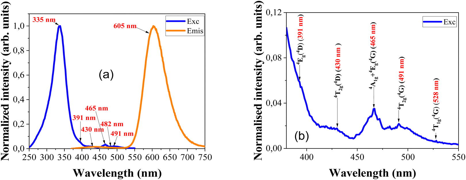 | ||
| Fig. 2 (a) Photoluminescence emission spectra under 335 nm UV excitation and excitation spectra recorded for the 605 nm emission peak, and (b) enlarged view of the d–d transition bands in the excitation spectra. | ||
| Terminating state | Wavelength and energy of the PLE peak |
|---|---|
| 4T1g (4G) | 528 nm (18939 cm−1) |
| 4T2g (4G) | 491 nm (20367 cm−1) |
| 4A1g + 4Eg (4G) | 465 nm (21505 cm−1) |
| 4T2g (4D) | 430 nm (23256 cm−1) |
| 4Eg (4D) | 391 nm (25575 cm−1) |
| C.T. | 335 nm (29851 cm−1) |
The emission spectrum is made up of two different bands: a very weak, broad blue luminescence band centred at 435 nm and an orange luminescence band at 605 nm. The blue band is likely related to defects in the host material, while the orange band is due to the 4T1 → 6A1 transition of the Mn2+ dopants, which replace Zn2+ ions. Previous studies have shown that with increasing Mn doping level the 4T1 → 6A1 emission-related band moves towards lower energies. Additionally, the intensity of this band grows with an increase in Mn doping concentration.27 Furthermore, the position of this main luminescence band slightly varies with changes in nanoparticle size. Fig. 2(a) shows the weak blue luminescent band at 435 nm compared to the highly intense orange emission at 605 nm.
The optical properties of the Mn2+ ions in ZnS can be explained by the d5 state of the Tanabe-Sugano diagram (discussed later). Fig. 3(a) shows the luminescence spectra of Mn2+-doped ZnS, which varies with temperature when excited with a 335 nm xenon lamp. The intensity of the main 4T1 → 6A1 luminescent band at 605 nm decreases with an increase in temperature from 4.5 to 300 K. Furthermore, this band shifts towards higher energies as the temperature increases (refer to Fig. 3(c)). The blue luminescence band also exhibits thermal quenching with an increase in temperature; however, the quenching is faster than that of the orange luminescence band at 605 nm. Earlier studies have compared Mn-doped ZnS samples with those doped with copper (Cu) and europium (Eu) and it was found that the emission from manganese-doped ZnS had a significantly slower quenching rate with increasing temperature than the other dopants.34Fig. 3(b) displays the integrated emission intensity (arb. units) of Mn2+ luminescence in ZnS versus temperature (T). The data were fitted with the following formula based on the Arrhenius equation:
 | (2) |
 | ||
| Fig. 3 (a) Temperature dependent Mn2+ luminescence spectra, (b) integrated emission intensity versus temperature (the red line shows the fit), (c) energy shift of the Mn2+ luminescence band versus temperature, and (d) full-width at half maximum of the emission peak versus temperature (the fit marked in red), (e) comparison of the X-ray excited radio-luminescence spectra and UV excited luminescence spectra of the ZnS:Mn2+ nanophosphor. | ||
The initial luminescence intensity of the Mn2+ luminescence band is represented by “I0”. The activation energy is denoted by “ΔE”, and “kB” is the Boltzmann constant. The intensity of the prominent Mn2+ band decreases with an increase in temperature from 4.5 K to 300 K, as shown in the fit of eqn (2) in Fig. 3(b). This indicates a thermally activated energy transfer process with activation energy of about 0.040 eV (40 meV). This value is greater than the 16 meV activation energy found in monocrystalline ZnS:Mn films35 and 23 meV determined in nano ribbons with a width of 100–800 nm.36 This indicates that the activation energy increases with decreasing crystallite size. A previous temperature-dependent study of ZnS:Mn nanoparticles shows the same value of 40 meV.37
The energy and FWHM versus temperature dependencies in Fig. 3(c) and (d) show that the Mn2+ emission band shifts to shorter wavelengths (higher energies) with increasing temperature. This behaviour is not typical and may testify to unusual thermal properties of ZnS, such as theoretically postulated negative thermal expansion (at least at low temperatures).38 Simultaneously the FWHM of the main luminescence band increases with the increase in temperature. The FWHM versus temperature dependence was fitted with the following equation:
 | (3) |
| EStokes = (2S − 1)ħΩ | (4) |
The Stokes shift calculated according to eqn (4) is equal to EStokes= 2552 cm−1. This Stokes shift added to the emission band centred at 605 nm yields the expected absorption peak of 6A1g → 4T1g (4G) transition at 524 nm, which is very close to the experimentally observed value presented in Table 1.
C3. Radio luminescence
The sample was investigated further with another type of excitation to check the Mn2+ luminescence consistency with other types of radiations, for this purpose the sample was excited with a continuous microfocus X-ray source. Fig. 3(e) shows the X-ray excited radio-luminescence spectrum of ZnS:Mn2+. The depicted luminescence curve is very similar to the spectrum in Fig. 2(a) obtained with UV excitation, consisting of both blue and orange luminescence bands. However, the defect-related emission band in the blue region is negligibly weak under X-ray excitation. Fig. 3(e) also shows the comparison of the main luminescence band related to the 4T1 → 6A1 transition of Mn2+ with both X-ray and UV excitations. This shows that both UV and X-ray excited emissions of Mn2+ are identical at ambient conditions and the FWHM values of both luminescence bands are also comparable: for UV it is 70.81 nm while for X-rays it is about 72.63 nm.C4. Impact-induced mechanoluminescence & EPR analysis
Fig. 4(a) and (b) show the impact-induced mechanoluminescence (I-ML) response of cubic and wurtzite ZnS:Mn samples with respect to time, collected after the samples were hit by a bullet from an air-soft electric gun.25 The bullet used for the impact studies in both cases had the same size and weight, as well as the same initial kinetic energy. The blue lines in Fig. 4(a) and (b) show the I-ML response without any earlier illumination and the red ones show the response after initial UV illumination of the samples for 2 minutes. When the bullet hits the sample, a piezoelectric field is created near the activator ions in the hitting area, which lowers the electron and hole trap depths near the activator ions and causes a release of carriers from filled traps to the conduction and valence bands.41 The recombination of the electron–hole pair releases some non-radiative energy, which excites the Mn2+ ions in the lattice and produces (orange in the case of zinc blende or yellow in the case of wurtzite samples) mechanoluminescence with impact. When it is previously illuminated with UV, more traps are filled and more recombination processes take place leading to luminescence enhancement. The current zinc blende structured ZnS:Mn sample shows a very good impact-induced mechanoluminescence response even without any external illumination and shows an improved luminescence response when the sample was previously illuminated with UV excitation. However, Cu or Ag-doped ZnS powders with scintillating properties do not show much mechanoluminescence when compared with Mn2+ doped ones.42 | ||
| Fig. 4 I-ML intensity versus time plot of ZnS:Mn samples ((a) zinc blende and (b) wurtzite) without any earlier irradiation and with earlier UV irradiation for 2 min (inset images show the respective sample films prepared for the I-ML experiments under UV light) | ||
For a better understanding, we compared the I-ML of our zinc blende sample with a wurtzite type ZnS:Mn (1%) sample (described previously)22–24 under the same experimental conditions. In comparison with the zinc blende, the wurtzite ZnS:Mn sample in Fig. 4(b) shows a much more intense and slightly broader I-ML response with time. This effect was previously related to the higher piezoelectric coefficient of wurtzite ZnS than that of ZnS with a zinc blende structure.
In contrast to the zinc blende, the wurtzite sample did not show any I-ML improvement upon initial illumination with a UV source. Moreover, room temperature EPR spectra of both samples collected at the same experimental conditions (presented in Fig. S1, ESI†) show that the wurtzite sample contains nearly 20 times more Mn2+ ions than the zinc blende sample that we synthesized, which is the reason for the much higher mechanoluminescence efficiency of the former in the spectrum in Fig. 4(b). The mechanoluminescence intensity enhancement for the wurtzite phase over the zinc blende was previously reported for a device fabricated with the ZnS material, where ML intensity enhancement was also observed while heating the sample over a temperature-induced phase transition from zinc blende to wurtzite, which is consistent with our observations.43,44 This means that the ZnS:Mn2+ phosphor samples in both phases are ideal for direct application in self-powered mechanoluminescence devices but in the case of zinc blende structured samples, the mechanoluminescence has the potential to be further enhanced by tuning of the Mn2+ dopant concentration, temperature, and external illumination power, etc. Also, both samples are promising when these nanoparticles are embedded in polymer materials, like PDMS, PVDF, etc., in future.45,46
The observation of higher Mn concentration in the wurtzite sample in EPR data is further confirmed by the comparison of room temperature and low-temperature SQUID measurements of both samples shown in Fig. S2 (ESI†). Both samples exhibit a paramagnetic behaviour related to Mn2+. The estimated ratio of the Mn content in both samples confirmed the result obtained from EPR intensity analysis. Only a small part of the initially introduced Mn enters the zinc blende quantum dots, despite the 0.02 M MnCl2 mixture added to the sample solution during synthesis. This gives a possibility of an increase in the ML efficiency of ZB type ZnS:Mn if a higher concentration of dopant is introduced to ZB ZnS. The apparently stronger crystal field experienced by Mn2+ ions in the ZB sample testifies to smaller cation–ion distances in this structure than in the WZ sample. This may be the reason for difficulties in substituting more Zn2+ ions by the larger Mn2+ ions.
C5. High-pressure luminescence studies
Fig. 5(a) and (b) show the pressure-dependent photoluminescence spectra of ZnS:Mn under ambient temperature conditions. Fig. 5(a) shows the change in emission spectra during compression and Fig. 5(b) shows the emission spectra with a decrease of pressure. Fig. 5(a) presents that initially the spectrum is very similar to the one we observed under ambient conditions; however, at the residual pressure it is slightly shifted to 610 nm from its original position at 605 nm. It also shows that with the increase of the pressure, the Mn2+ luminescence gradually shifts up to the NIR region of around 800 nm at high pressure and the luminescence is completely quenched at 16.41 GPa. This means that a phase transition occurs around this pressure. Most probably, at this pressure the Mn-doped ZnS nanoparticle loses its zinc blende structure (F3m) and transforms into the rock salt (Fmm) phase. Earlier DFT studies also pointed to the zinc blende to rock salt phase transition happening somewhere near 14.7 and 17.6 GPa and it also suggests that the zinc blende structure is more compressible than the rock salt one.47,48 Also, the main luminescence band shifts to nearly 775 nm (1.6 eV) during compression, which is in the NIR bio-window region. Fig. 5(b) proves that the zinc blende to rock salt phase transition is reversible because the sample luminescence returns to its initial position and regains its original luminescence intensity after decompression. Previous synchrotron studies of ZnS nanoparticles with a zinc blende structure exhibited a reversible phase transition compared to the ZnS nanoparticles with a wurtzite phase.49 It is also evident that the particle size also greatly influences the phase transition pressure of the ZnS nanophosphor.50
 | ||
| Fig. 5 Pressure-dependent luminescence of Mn2+ under increase (a) and release (b) of pressure. (c) Energy versus pressure and (d) integrated emission intensity versus pressure. (e) Phase transition from zinc blende structure to rock salt under high pressure (yellow balls indicate zinc (Zn) and blue balls indicate sulphur (S) atoms, respectively). | ||
Fig. 5(c) shows the linear decrease of energy with the gradual increase of pressure. The pressure coefficient was calculated by the linear fit of the data and it is about −35.8 meV GPa−1. It is comparable to the values reported by the previous high-pressure studies of ZnS nanoparticles of similar structure and dimensions shown in Table 2. However, compared to the bulk crystal, the ZnS:Mn2+ nanoparticle has a slightly higher pressure coefficient due to the higher surface-to-volume ratio.13,14Fig. 5(d) depicts the dependence of integrated emission intensity on pressure. It shows the gradual decrease of the emission intensity with the increase of pressure. Furthermore, at 16.41 GPa, the luminescence intensity is completely quenched. Both graphs in Fig. 5(c) and (d) clearly show that the orange luminescence gradually shifts from the visible (2.04 eV) to the near-infrared region (1.62 eV) and completely disappears with further increase of pressure due to phase transformation.
| Host | Dopant | Sample size | Structure | Study | Max. pressure reached (GPa) | Phase transition (GPa) | Pressure coefficient (meV GPa−1) | Year | Ref. |
|---|---|---|---|---|---|---|---|---|---|
| a ADXRD - Angle dispersive X-ray diffraction. | |||||||||
| ZnS | Mn2+ | 1 nm | * | PL | ∼7 | No | −31.6 | 2003 | 14 |
| 3 nm | −33.1, | ||||||||
| 3.5 nm | −30.9, | ||||||||
| 4.5 nm | −31.9, | ||||||||
| 10 nm | −29 | ||||||||
| Bulk | |||||||||
| 3 nm | * | PL | ∼7 | No | −39, | 2004 | 13 | ||
| 3.5 nm | −35.7, | ||||||||
| 4.5 nm | −33.3, | ||||||||
| 10 nm | −30.1, | ||||||||
| Bulk | −29.4 | ||||||||
| * | * | PL | ∼5 | No | * | 1966 | 12 | ||
| 4.5 nm | Zinc blende | PL | ∼7 | No | −33.3 | 2000 | 51 | ||
| * | Zinc blende | PL | ∼12 | No | −31 | 1977 | 52 | ||
| Bulk | * | Absorption & PL | ∼10 | No | −26.5 | 1988 | 53 | ||
| Undoped | Bulk 3.5 to 4.5 μm | Zinc blende | Absorption | ∼20 | 15 | 1990 | 54 | ||
| Zinc blende | X-ray | ∼35 | 13.4 | * | 2017 | 55 | |||
| 2.8 nm | Zinc blende | X-ray | ∼20 | 18 | * | 2000 | 49 | ||
| Nanosheets (20–50 nm) | Zinc blende | ADXRDa | ∼33 | 13.1 | * | 2015 | 56 | ||
| Bulk | Zinc blende | Shock | ∼ 135 | 15.7 | 1998 | 57 | |||
| * | Zinc blende | DFT | ∼25 | 14.7 | * | 2019 | 47 | ||
| * | Zinc blende | DFT | * | 17.6 | 2015 | 48 | |||
| Mn2+ | 2.38 nm | Zinc blende | PL | ∼17 | 16.41 | −35.8 | Present | ||
C6. Luminescence decay studies
For a better understanding of the influence of temperature and pressure on the Mn2+ luminescence band, the decay analysis of the sample was performed as a function of both temperature and pressure. The temperature-dependent decay measurements performed at temperatures ranging from 4 K to 300 K are shown in Fig. 6(a); the sample was excited with 335 nm xenon lamp excitation and emission was collected at 610 nm of the main luminescent band related to the 4T1 → 6A1 transition. Fig. 6(a) shows that the decay time at higher temperatures is a little bit faster than the decay at lower temperatures. The obtained decay curves are fitted with a double exponential equation. The fitted results in Fig. 6(c) show that both decay time components τ1 and τ2 have a milliseconds lifetime and it decreases with an increase in temperature. Both the τ1 and τ2 components decrease in a similar manner. | ||
| Fig. 6 (a) Temperature and (b) pressure-dependent photoluminescence decay kinetics of the Mn2+ peak in ZnS, and decay time versus (c) temperature, and (d) pressure. | ||
Initially, the τ2 component of the decay time at 4.5 K was around 3.68 ms and it decreased nearly to 3.2 ms at 300 K. The τ1 was around 1.33 ms at 4.5 K and it decreased nearly to 0.93 ms at 300 K. The milliseconds decay time of the τ2 component confirms the perfect incorporation of a higher percentage of Mn2+ ions inside the ZnS nanoparticles, rather than over the surface. The other τ1 component indicates the occupation of a few percentages of ions closer to the surface. To know more about the high-pressure phase transition and luminescence quenching behaviour of the ZnS:Mn sample, pressure-dependent decay kinetics were also measured. Fig. 6(b) shows the pressure-dependent decay kinetics of Mn2+ luminescence. Unlike the temperature-dependent spectra, an additional decay component was also observed during the high-pressure DAC measurement; probably it is due to the use of a pulsed laser excitation source. In an earlier comparison study in the ZnS:Mn2+ sample, a similar additional component was observed with pulsed laser excitation as with the xenon lamp at ambient conditions.27 However, the luminescence decay time values for τ1 and τ2 at 300 K in Fig. 6(c) are close to the τ2 and τ3 values of the sample measured at 0 GPa (without DAC) in Fig. 6(d). Fig. 6(d) also shows that all three lifetime decay components τ1, τ2, and τ3 decrease during compression. The τ3 component decreased from 2.98 ms to nearly 1.97 ms, the τ2 component decreased from 0.99 ms to 0.44 ms and the τ1 component decreased from 0.28 ms to 0.067 ms at a pressure of 15.24 GPa. The τ3 component shows a larger shift in decay time with compression rather than the two other components. The Mn2+ luminescence was completely quenched at the next pressure step due to the induced zinc blende to rock salt phase transition described earlier, and because of that the signal was reduced to background noise. However, earlier pressure-dependent decay analysis of the ZnS:Mn sample up to 12 GPa did not show much shift in the main decay component despite an unusual increase in luminescence intensity under high pressure, and also they did not go up to the phase transition point.52
D. Discussion
The observation of pressure and temperature-dependent multi-exponential luminescence decay times in milliseconds indicates the occupation of Mn2+ ions in different places in the ZnS nanocrystal. The longer decay component of nearly 3 ms in both experiments indicates the occupation of Mn2+ ions in the non-perturbed cation sites and the decay component of nearly 1 ms probably belongs to the Mn2+ ions occupied in the lattice sites closer to the surface of the nanocrystals. However, the additional low-intensity decay component that shifted from milliseconds to microseconds during the high-pressure study using the pulsed laser is either from the Mn2+ ions occupied on the lattice sites of the surface of the nanocrystal or from the tale of the blue emission that overlapped with the orange band related to the 4T1 → 6A1 of Mn2+.58 Moreover, a similar three exponential decay behaviour was also observed in ZnS phosphor doped with 5% Mn2+ synthesized via a reverse micelle route,59 and the minor size difference in ZnS:Mn2+ nanoparticles also significantly influences the decay time values.60The Mn2+ ion luminescence in ZnS in Fig. 2(a) is also interpreted with the crystal field theory and Tanabe Sugano (T-S) diagrams; it explains the electronic absorption energy levels and crystal field strength of the Mn2+ present in the material. The strength of the crystal field is also influenced by the size of the nanoparticle. Due to the half-filled 3d5 electronic configuration of the Mn2+ ion, the d5 configuration of the T-S diagram is used for the calculations and it is designed with Racah parameters B, C, and crystal field strength Dq. The most probable values for this can be obtained by the fit of the crystal-field theory and 10 Dq = Δ = 4526 cm−1, B = 580 cm−1, C = 3140 cm−1, Δ/B = 7.8, and C/B = 5.41. Moreover, the theoretically obtained crystal field levels 4T1(4G) at 528 nm, 4T2(4G) at 482 nm, 4A1, and 4E (4G) at 465 nm are comparable with the experimentally obtained values in Table 1. The Racah parameters B and C were calculated from the following equations:
| 4A1g + 4Eg (4G) → 10B + 5C | (5) |
| 4Eg (4D) → 17B + 5C | (6) |
The experimentally obtained values for 4Eg (4D) and 4A1g + 4Eg (4G) are 391 nm (25575 cm−1) and 465 nm (21505 cm−1), respectively, from the excitation spectra. As pressure increases, the main Mn2+ luminescence band related to the 4T1 → 6A1 transition changes towards a higher crystal field in the T-S diagram. In other words, the energy of this quartet 4T1g level progressively diminishes as the strength of the crystal field increases. Fig. 5(c) shows a linear decrease in the energy of the main luminescence band with the increase of pressure but the Mn2+ luminescence band is completely quenched before the crossing point between the quartet 4T1g level and the doublet 2T2 level in the T-S diagram due to the zinc blende to rock salt phase transition near 16.41 GPa. However, the strongly spin forbidden transitions to the 2T2 level are not visible in the excitation spectra. Previous pressure-induced quenching of Mn2+ luminescence belonging to the same d5 system was observed because of the crossing between the radiative 4T1g level and the non-radiative 2T2 level.61 Another pressure-induced study of the Fe3+-doped oxide sample belonging to the same d5 class of systems shows a luminescence quenching near 14 GPa due to phase transition.62 Despite the quenching of the 4T1 → 6A1 luminescence band (due to the aforementioned phase transition and a decrease in the distance between the 4T1g level and the non-radiative 2T2 level with the increase of pressure), it is evident that the overall decay times of the Mn2+ions in ZnS are weakly affected by the increase in strength of the crystal field.
Conclusions
Pressure and temperature-dependent luminescence analysis of a zinc blende structured ZnS nanophosphor nominally doped with 2% of Mn2+ was successfully performed. The phosphor contains nanocrystallites with near quantum dot size (of 2.38 nm on average) that were synthesized by the chemical precipitation method, showing intense UV and X-ray induced luminescence at ambient conditions. Also, it has highly desirable self-powered mechanoluminescence properties at ambient temperature conditions without any external irradiation source and it gradually increases with external irradiation. Additionally, the high-pressure luminescence analysis using a diamond anvil cell confirms that the bright orange Mn2+ luminescence shifted from the visible to the near-infrared spectral region and was completely quenched due to a reversible phase transition from zinc blende to rock salt structure near 16.41 GPa. The sample retained its initial bright orange luminescence after the complete release of pressure, compared to the irreversible phase transition of the ZnS:Mn2+ phosphor with a wurtzite structure.49,63 The milliseconds decay times also confirm the perfect incorporation of Mn2+ ions inside the host lattice and show that the multi-exponential Mn2+ decay time is influenced by both pressure and temperature.Author contributions
AKS – investigation, writing – original draft, review & editing, data curation, YaZh, DW, SSH, KRB, YKE, TZ, ASz, SN, AL, HP, EIA – investigation, JB – investigation, conceptualization, AS – conceptualization, project administration, resources, validation, writing – review & editing.Conflicts of interest
There are no conflicts to declare.Acknowledgements
This work was partially supported by the National Science Centre, Poland, grant SHENG 2 number: 2021/40/Q/ST5/00336 and NCN project number 2019/33/B/ST8/02142.The ZnS:Mn (1%) wurtzite sample was kindly provided by Prof. Dengfeng Peng.
References
- S. Carturan, G. Maggioni, M. Cinausero, T. Marchi, F. Gramegna, F. Pino, D. Fabris and A. Quaranta, J. Nucl. Physics, Mater. Sci. Radiat. Appl., 2016, 4, 107–116 Search PubMed.
- T. Yanagida and Y. Fujimoto, Jpn. J. Appl. Phys., 2014, 53, 032601 Search PubMed.
- G. M. I. Korotcenkov, Handbook of II-VI Semiconductor-Based Sensors and Radiation Detectors, 2023, pp. 75–108 Search PubMed.
- S. Ebrahimi, B. Yarmand and N. Naderi, Sens. Actuators, A, 2020, 303, 111832 Search PubMed.
- L. Ma, K. Jiang, X. T. Liu and W. Chen, J. Appl. Phys., 2014, 115, 103104 Search PubMed.
- E. V. Zelenina, V. V. Bakhmetyev, M. M. Sychov and M. A. Shvindin, Mater. Sci. Forum, 2021, 1040, 35–40 Search PubMed.
- X. Li, X. Zhu, H. Tang, J. Zhang, M. Zhou, Q. Peng, B. Meng, S. Wang, A. N. Yakovlev, L. Zhao, J. Yu and X. Xu, Inorg. Chem., 2023, 62, 7914–7920 Search PubMed.
- M. Saleh, K. G. Lynn, L. G. Jacobsohn and J. S. McCloy, J. Appl. Phys., 2019, 125, 075702 Search PubMed.
- M. Stefan, S. V. Nistor, D. Ghica, C. D. Mateescu, M. Nikl and R. Kucerkova, Phys. Rev. B: Condens. Matter Mater. Phys., 2011, 83, 045301 Search PubMed.
- K. R. Bindu and E. I. Anila, J. Fluoresc., 2015, 25, 795–801 Search PubMed.
- K. R. Bindu, S. Ajeesh Kumar, M. Anilkumar and E. I. Anila, Solid State.Commun., 2021, 323, 114106 Search PubMed.
- T. Koda, S. Shionoya, M. Ichikawa and S. Minomura, J. Phys. Chem. Solids, 1966, 27, 1577–1586 Search PubMed.
- G. H. Li, F. H. Su, B. S. Ma, K. Ding, S. J. Xu and W. Chen, Phys. Status Solidi B, 2004, 241, 3248–3256 Search PubMed.
- F. H. Su, Z. L. Fang, B. S. Ma, K. Ding, G. H. Li and W. Chen, J. Phys. Chem. B, 2003, 107, 6991–6996 Search PubMed.
- N. P. Bergeron, S. M. Goedeke, W. A. Hollerman, C. I. Muntele, S. W. Allison and D. Ila, AIP Conf. Proc., 2005, 746, 762–767 Search PubMed.
- W. A. Hollerman, S. M. Goedeke, N. P. Bergeron, C. I. Muntele, S. W. Allison and D. Ila, Nucl. Instrum. Methods Phys. Res., Sect. B, 2005, 241, 578–582 Search PubMed.
- B. P. Chandra, S. Parganiha, V. K. Chandra, P. Jha, V. D. Sonwane and R. N. Baghel, J. Lumin., 2016, 180, 151–157 Search PubMed.
- L. R. Gauthier, Jr., M. E. Jansen and J. R. Meyer, Fiber Opt. Sensors Appl. VI, 2009, 7316(731618), 1–11 Search PubMed.
- W. A. Hollerman, S. M. Goedeke, S. W. Allison, P. A. Gray and L. A. Lewis, IEEE Nucl. Sci. Symp. Conf. Rec., 2005, 3, 1284–1287 Search PubMed.
- R. S. Fontenot, W. A. Hollerman, M. S. Steuart and B. M. Broussard, Proc. 12th Int. Conf. Eng. Sci. Constr. Oper. Challenging Environ. - Earth Sp. 2010, 2560–2567.
- S. Goedeke, N. Bergeron, W. Hollerman, S. Allison, F. Womack, C. Muntele and D. Ila, In 41st AIAA/ASME/SAE/ASEE Joint Propulsion Conference & Exhibit, 2005. p. 3781.
- T. Zheng, M. Runowski, I. R. Martín, K. Soler-Carracedo, L. Peng, M. Skwierczyńska, M. Sójka, J. Barzowska, S. Mahlik, H. Hemmerich, F. Rivera-López, P. Kulpiński, V. Lavín, D. Alonso and D. Peng, Adv. Mater., 2023, 35(40), 2304140 Search PubMed.
- R. Ma, C. Wang, W. Yan, M. Sun, J. Zhao, Y. Zheng, X. Li, L. Huang, B. Chen, F. Wang, B. Huang and D. Peng, Nano Res., 2022, 15, 4457–4465 Search PubMed.
- R. Ma, X. Wei, C. Wang, S. Mao, B. Chen, Y. Shao, Y. Fu, K. Yan and D. Peng, J. Lumin., 2021, 232, 117838 Search PubMed.
- S. S. Haider, J. Barzowska, P. Sybilski and A. Suchocki, Measurement, 2022, 203, 112012 Search PubMed.
- S. Joicy, R. Saravanan, D. Prabhu, N. Ponpandian and P. Thangadurai, RSC Adv., 2014, 4, 44592–44599 Search PubMed.
- N. T. Tuan, D. Q. Trung, N. V. Quang, N. D. Hung, N. T. Khoi, P. T. Huy, P. F. Smet, K. W. Meert and D. Poelman, J. Lumin., 2018, 199, 39–44 Search PubMed.
- A. Bala, R. Sehrawat, A. K. Sharma and P. Soni, J. Mater. Sci.: Mater. Electron., 2021, 32, 16382–16391 Search PubMed.
- R. D. Yang, S. Tripathy, F. E. H. Tay, L. M. Gan and S. J. Chua, J. Vac. Sci. Technol., B: Microelectron. Nanometer Struct.--Process., Meas., Phenom., 2003, 21, 984–988 Search PubMed.
- O. Brafman and S. S. Mitra, Phys. Rev., 1968, 171, 931–934 Search PubMed.
- Y. C. Cheng, C. Q. Jin, F. Gao, X. L. Wu, W. Zhong, S. H. Li and P. K. Chu, J. Appl. Phys., 2009, 106, 123505 Search PubMed.
- W. G. Nilsen, Phys. Rev., 1969, 182, 838–850 Search PubMed.
- R. N. Bhargava, D. Gallagher, X. Hong and A. Nurmikko, Phys. Rev. Lett., 1994, 72, 416–419 Search PubMed.
- F. H. Su, Z. L. Fang, B. S. Ma, K. Ding, G. H. Li and S. J. Xu, J. Appl. Phys., 2004, 95, 3344–3349 Search PubMed.
- W. Park, T. C. Jones, W. Tong, S. Schön, M. Chaichimansour, B. K. Wagner and C. J. Summers, J. Appl. Phys., 1998, 84, 6852–6858 Search PubMed.
- J. Lu, X. Zeng, H. Liu, W. Zhang and Y. Zhang, J. Phys. Chem. C, 2012, 116, 23013–23018 Search PubMed.
- J. F. Suyver, J. J. Kelly and A. Meijerink, J. Lumin., 2003, 104, 187–196 Search PubMed.
- S. Q. Wang, Appl. Phys. Lett., 2006, 88, 061902 Search PubMed.
- W. Chen, R. Sammynaiken, Y. Huang, J. O. Malm, R. Wallenberg, J. O. Bovin, V. Zwiller and N. A. Kotov, J. Appl. Phys., 2001, 89, 1120–1129 Search PubMed.
- H. Ajiki, Phys. Status Solidi, 2001, 224, 633–637 Search PubMed.
- P. Sharma, R. Daipuriya, A. Bhagatji, S. Tyagi and S. S. Pal, Opt. Mater., 2021, 122, 111798 Search PubMed.
- B. P. Chandra, J. Lumin., 2011, 131, 1203–1210 Search PubMed.
- X. Wang, H. Zhang, R. Yu, L. Dong, D. Peng, A. Zhang, Y. Zhang, H. Liu, C. Pan and Z. L. Wang, Adv. Mater., 2015, 27, 2324–2331 Search PubMed.
- X. Zhang, X. Li, B. Ren, X. Li, Y. Lu, C. Wang and D. Peng, Sci. Bull., 2023, 68, 2487–2490 Search PubMed.
- A. Qasem, P. Xiong, Z. Ma, M. Peng and Z. Yang, Laser Photonics Rev., 2021, 15, 1–20 Search PubMed.
- H. Liu, Y. Zheng, S. Liu, J. Zhao, Z. Song, D. Peng and Q. Liu, Adv. Funct. Mater., 2024, 2314422, 1–9 Search PubMed.
- G. Ulian and G. Valdrè, Acta Crystallogr., Sect. B: Struct. Sci., Cryst. Eng. Mater., 2019, 75, 1042–1059 Search PubMed.
- K. Kabita, J. Maibam, B. I. Sharma, R. K. Brojen Singh and R. K. Thapa, Adv. Sci. Lett., 2015, 21, 2906–2910 Search PubMed.
- S. B. Qadri, E. F. Skelton, A. D. Dinsmore, J. Z. Hu, W. J. Kim, C. Nelson and B. R. Ratna, J. Appl. Phys., 2001, 89, 115–119 Search PubMed.
- J. Z. Jiang, L. Gerward, D. Frost, R. Secco, J. Peyronneau and J. S. Olsen, J. Appl. Phys., 1999, 86, 6608–6610 Search PubMed.
- W. Chen, G. Li, J. Malm, Y. Huang and R. Wallenberg, J. Lumin., 2000, 91, 139–145 Search PubMed.
- G. L. House and H. G. Drickamer, J. Chem. Phys., 1977, 67, 3230–3237 Search PubMed.
- K. Mayrhofer, K. Hochberger and W. Gebhardt, J. Phys. C-Solid State Phys., 1988, 21, 4393–4401 Search PubMed.
- S. Ves, U. Schwarz, N. E. Christensen, K. Syassen and M. Cardona, Phys. Rev. B: Condens. Matter Mater. Phys., 1990, 42, 9113–9118 Search PubMed.
- S. Ono and T. Kikegawa, Phase Transitions, 2018, 91, 9–14 Search PubMed.
- Z. Li, J. Wang, B. Liu and J. Liu, J. Phys. Chem. C, 2016, 120, 781–785 Search PubMed.
- M. Uchino, T. Mashimo, M. Kodama, T. Kobayashi, T. Takasawa, T. Sekine, Y. Noguchi, H. Hikosaka, K. Fukuoka, Y. Syono, T. Kondo and T. Yagi, J. Phys. Chem. Solids, 1999, 60, 827–837 Search PubMed.
- A. Bol and A. Meijerink, Phys. Rev. B: Condens. Matter Mater. Phys., 1998, 58, R15997–R16000 Search PubMed.
- R. M. Krsmanović Whiffen, D. J. Jovanović, Z. Antić, B. Bártová, D. Milivojević, M. D. Dramićanin and M. G. Brik, J. Lumin., 2014, 146, 133–140 Search PubMed.
- L. Chen, F. J. Brieler, M. Fröba, P. J. Klar and W. Heimbrodt, Phys. Rev. B: Condens. Matter Mater. Phys., 2007, 75, 7–10 Search PubMed.
- L. I. Bulyk, L. Vasylechko, V. Mykhaylyk, C. Tang, Y. Zhydachevskyy, Y. A. Hizhnyi, S. G. Nedilko, N. I. Klyui and A. Suchocki, Dalton Trans., 2020, 49, 14268–14279 Search PubMed.
- A. K. Somakumar, L. I. Bulyk, V. Tsiumra, J. Barzowska, P. Xiong, A. Lysak, Y. Zhydachevskyy and A. Suchocki, Inorg. Chem., 2023, 62, 12434–12444 Search PubMed.
- H. Wang, X. Chen, J. Li, M. Li, K. Liu, D. Yang, S. Peng, T. Zhao, B. Zhao, Y. Li, Y. Wang, C. Lin and W. Yang, ACS Appl. Mater. Interfaces, 2023, 15, 28204–28214 Search PubMed.
Footnote |
| † Electronic supplementary information (ESI) available: The supplementary material contains the results of EPR and SQUID measurements of both ZB and WZ samples, showing that the Mn2+ concentration is about 19 times larger in WZ than in the ZB sample. See DOI: https://doi.org/10.1039/d4tc00960f |
| This journal is © The Royal Society of Chemistry 2024 |