
 Open Access Article
 This Open Access Article is licensed under a Creative Commons Attribution-Non Commercial 3.0 Unported Licence
Structural insights to metal ion linked multilayers on metal oxide surfaces via energy transfer and polarized ATR measurements†
Ashley
Arcidiacono
a,
Cory
Ruchlin
 b,
Grace M.
McLeod
a,
Dhruba
Pattadar
c,
Sarah
Lindbom
a,
Alex J.
Robb
a,
Suliman
Ayad
a,
Nikolas R.
Dos Santos
a,
Igor V.
Alabugin
a,
S. Scott
Saavedra
c and
Kenneth
Hanson
*a
b,
Grace M.
McLeod
a,
Dhruba
Pattadar
c,
Sarah
Lindbom
a,
Alex J.
Robb
a,
Suliman
Ayad
a,
Nikolas R.
Dos Santos
a,
Igor V.
Alabugin
a,
S. Scott
Saavedra
c and
Kenneth
Hanson
*a
aDepartment of Chemistry and Biochemistry, Florida State University, Tallahassee, Florida 32306, USA. E-mail: hanson@chem.fsu.edu
bDepartment of Chemistry, McGill University, 801 Sherbrooke Street West, Montreal, Quebec H3A 0B8, Canada
cDepartment of Chemistry and Biochemistry, University of Arizona, Tucson, Arizona 85721, USA
First published on 25th September 2024
Abstract
Metal ion linked multilayers offer a means of controlling interfacial energy and electron transfer for a range of applications including solar energy conversion, catalysis, sensing, and more. Despite the importance of structure to these interlayer transfer processes, little is known about the distance and orientation between the molecules/surface of these multilayer films. Here we gain structural insights into these assemblies using a combination of UV-Vis polarized visible attenuated total reflectance (p-ATR) and Förster Resonance Energy Transfer (FRET) measurements. The bilayer of interest is composed of a metal oxide surface, phosphonated anthracene molecule, Zn(II) linking ion, and a platinum porphyrin with one (P1), two (P2), or three (P3) phenylene spacers between the chromophoric core and the metal ion binding carboxylate group. As observed by both time-resolved emission and transient absorption, the FRET rate and efficiency decreases with an increasing number of phenylene spacers (P1 > P2 > P3). However, from p-ATR measurements we observe a change in orientation of porphyrins in the bilayer, which inhibits a uniform determination of the orientation factor (κ2) across the series. Instead, we narrow the scope of viable structures by determining the best agreement between experimental and calculated FRET efficiencies. Additionally, we provide evidence that suggests, for the first time, that the bilayer structure is similar on both planar and mesoporous substrates.
Introduction
The assembly of multiple molecular components at a metal oxide surface is of interest for their application in solar energy conversion, photocatalysis, sensing and more.1–3 Of the strategies for combining molecules at an interface (e.g., electrostatics, co-deposition, covalent dyads, etc.),4 metal ion linked multilayers are appealing because (1) they are generated via a simple step-wise soaking procedure, (2) they avoid the synthetic complexities of covalently-bound dyads, (3) the components are modular, and (4) they circumvent the surface area limitation of co-deposited films.3 The strategic selection of components (e.g., chromophores, catalysts, electron donors and/or acceptors, etc.) and their proximity to the surface can be used to facilitate directional energy and electron transfer as desired for their application in photon upconversion,5–7 solar energy conversion,8 photocatalysis,9–11 molecular rectifying interfaces,12–15 and electrochromism.16The rate and efficiency of these interfacial energy and electron transfer events are not only dependent on the energetics of the components but also the structure of the assembly (i.e., the distance and orientation between the molecules/surface). In terms of structural insights into metal ion linked multilayers, the molecular and metal ion ratios have been quantified using UV-Vis spectroscopy, XPS, and mass spectrometry.3,17,18 Metal ion coordination and multilayer thickness have been determined from IR spectroscopy, atomic force microscopy, ellipsometry, X-ray photoelectron spectroscopy, and UV-Vis spectroscopy.3,19–22
Recently, our team was the first to use polarized UV-Vis attenuated total reflectance (p-ATR) spectroscopy to determine the transition dipole moment orientation of each molecular layer23 in metal ion linked bilayer24 and trilayer films.25 While p-ATR, and other grazing angle techniques (e.g., XRR, IRRAS, etc.),26–28 lend some insight into the structure at molecule-metal oxide interfaces, they suffer from two fundamental limitations relevant to the materials discussed here. First, these measurements are performed on planar surfaces which may or may not accurately represent the structure on mesoporous substrates.29 Second, they can only provide information about the molecular orientation relative to the substrate.30,31 The later issue is particularly problematic for multimolecular systems because, in the absence of an additional frame of reference (i.e., the azimuthal angle), they cannot provide the orientation of the molecules relative to each other.25
In this manuscript we describe our effort to address these shortcomings by using p-ATR in conjunction with Förster Resonance Energy Transfer (FRET) measurements to determine the structure of a metal ion-linked bilayer assembly. The bilayer of interest is shown in Fig. 1 and is composed of a mesoporous zirconium oxide substrate (ZrO2), phosphonated anthracene molecule (A), Zn(II) linking ion, and a carboxylated, unsymmetric porphyrin (PX, where X = the number of phenylene spacers, 1, 2, or 3).
 | ||
| Fig. 1 General depiction of a metal ion linked bilayer composed of a ZrO2 substrate, A (red), Zn(II) linking ion (green), and PX (blue) where X is the number of phenylene spacers. The directionality and rate constant for TET and FRET are depicted in purple and orange, respectively. | ||
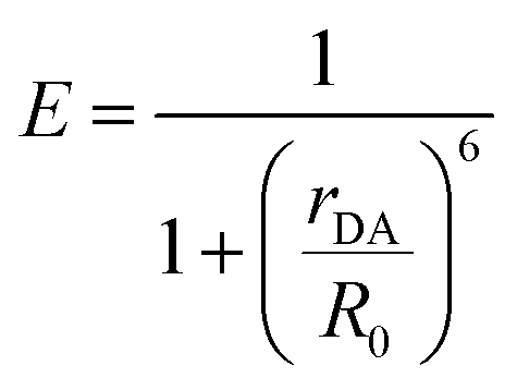
This bilayer (ZrO2-A-Zn-PX) was chosen because it is a derivative of our previously studied molecular photon upconversion films,5,24,32,33 and it has appropriate energetics for 3PX* to A triplet energy transfer (TET) and 1A* to PX FRET.32 The latter energy transfer process, FRET, is particularly important here as it has well-known distance and orientation dependences as described in eqn (1) and (2).34–36
 | (1) |
| R0 = 9780(κ2ΦDn−4J)1/6 | (2) |
κ2 = (cos![[thin space (1/6-em)]](https://www.rsc.org/images/entities/char_2009.gif) α − 3cosβcosγ)2 α − 3cosβcosγ)2 | (3) |
For a fixed pair of chromophores where J, n, and ΦD are constant, then the relationship between measured values of E with respect to systematic variation in rDA (i.e., n = 1–3 in Fig. 1) could be used to determine κ2 and, by extension, the relative orientation of the molecules in the bilayer film.37,38 That, in conjunction with p-ATR measurements (i.e., the orientation relative to the surface), could provide a unique average geometry of the bilayer film.
Below, we recount our efforts using time-resolved emission and transient absorption to quantify the energy transfer rates and yields in the bilayer film depicted in Fig. 1. p-ATR is then used to determine the orientation of the chromophores relative to the surface. Due to orientation changes among P1, P2, and P3 and the added complexity of the degenerate coplanar transition dipoles of PX, we were unable to determine a unique structure. Instead, we used calculated and experimental FRET efficiencies to narrow the scope of possible structures.
Experimental
Materials
Zinc acetate, boron trifluoride diethyl etherate, chloroform, benzonitrile, potassium hydroxide, methanol, dichloromethane, hexanes, and acetonitrile were purchased from Sigma-Aldrich and used without any further purification. 3,5-Di-tert-butylbenzaldehyde was purchased from Sigma-Aldrich and recrystallized from ethanol three times prior to use. 2,3-Dichloro-5,6-dicyano-p-benzoquinone (DDQ) and methyl 4-formyl benzoate were purchased from Alfa Aesar and used without further purification. Pyrrole was purchased from Sigma-Aldrich and distilled over calcium hydride (Sigma-Aldrich) prior to use. Benzonitrile was purchased from Sigma-Aldrich and distilled prior to use. Melatonix film and Vac'n Fill syringes were purchased from Solaronix. Glass substrates were acquired from Hartford Glass Co. Micro glass cover slides (18 × 18 mm) were obtained from VWR. ZrO2 solgel pastes were prepared following previously reported procedures.39A40 and P3 (ref. 41) were synthesized following previously reported procedure. Synthetic details for P1 and P2 can be found in ESI.†Film loading
Mesoporous ZrO2 on glass substrates was functionalized with monolayers of Avia soaking in a loading solution of 200 μM A in DMSO for 48 h. For the coordination of Zn(II), films were then submerged in a solution of Zn(CH3COO)2 in MeOH (500 μM) for 2 h, followed by 150 μM P1/P2 or 9.0 mg in 60 mL of P3 in 1:1 chloroform:methanol until an A:PX ratio of ∼10:1 was reached (15 minutes for P1/P2 and 3 h for P3), resulting in ZrO2-A-Zn-PX. Surface coverage isotherms can be found in ESI.† Films on planar ITO were loaded via a liquid flow cell using the conditions listed in Table S5.† The adsorption isotherms (obtained with transverse magnetic polarized light) can be found in ESI.†
Absorption spectroscopy
Absorption spectra were acquired using an Agilent 8453 UV-visible photo diode array spectrophotometer. Thin film absorption spectra were collected via placing functionalized metal oxide films perpendicular to the detection path.Steady-state and time-resolved emission
An Edinburgh FLS980 fluorescence spectrometer was used to obtain emission spectra. A 450 W Xe lamp coupled with a single grating (1800 l mm−1, 250 nm blaze) Czerny–Turner monochromator was used as output to excite the samples. Sample emission was passed through a 435 nm long pass filter then a single grating (1800 l mm−1, 500 nm blaze) Czerny–Turner monochromator and then detected by a Peltier-cooled Hamamatsu R928 photomultiplier tube. Time-resolved emission was collected at room temperature using the same Edinburgh FLS980 fluorescence spectrometer. Emission decay kinetics were obtained using multichannel scaling (MCS; >1 μs) or time-correlated single photon counting (TCSPC; <1 μs) with data collection until 10000 counts. MCS measurements utilized excitation output from a 60 W microsecond flashlamp (pulse width <2.5 μs) at a 100 Hz repetition rate passed through a single grating (1800 l mm−1, 250 nm blaze) Czerny–Turner monochromator. Excitation for TCSPC was generated by an Edinburgh EPL-360 ps pulsed light emitting diode (360 ± 10 nm, pulse width 890 ps) with emission then passed through a single grating (1800 l mm−1, 500 nm blaze) Czerny–Turner monochromator and detected by a Peltier-cooled Hamamatsu R928 photomultiplier tube. For kinetics on films, a biexponential fitting using an IRF deconvolution24 was used and a weighted average lifetime is reported.
Transient absorption
Transient absorption measurements were obtained using a HELIOS Fire transient absorption spectrometer (Ultrafast Systems). The spectrometer was coupled to the output of a Vitara-S Coherent Ti:sapphire laser amplifier using a 1 kHz Coherent Revolution-50 pump laser (5 mJ pulse, 150 fs fwhm at 800 nm). This output was split into a pump and probe beam. The probe was passed through a delay stage while the pump traveled through an optical parametric amplifier (OPerA Solo from Coherent) for wavelength selection. A white light supercontinuum, used for the probe, was produced by a sapphire crystal. The pump and probe beam were then overlapped on the sealed, deaerated sample that was mounted in a rastering stage. Difference spectra and single wavelength kinetics were collected averaging 3 times and holding for 3 seconds, with an exponential point acquisition beginning with 0.01 ps steps and totalling to 250 points. Chirp correction was processed using the Surface Xplorer software package from Ultrafast Systems.Polarized visible attenuated total reflectance (p-ATR)
ATR spectroscopy measurements were conducted using a spectrometer described previously.42 ITO-coated glass slides (Thin Film Devices) served as planar waveguides. A Xe lamp (polarized and collimated) was coupled into and out of the waveguide using two BK7 (n = 1.51) prisms. The outcoupled light was directed into a monochromator (Newport MS260i) using a fiber-optic cable and was detected by a CCD camera (Andor iDus420A). The mean tilt angles of the absorbance dipoles of A in monolayer films and A and porphyrins in bilayer films were determined using previously described methods.31Atomic layer deposition (ALD)
Glass microscope cover slides (VWR) were first sonicated in an HCl/ethanol (15/85% mix) solution for 20 minutes and then ethanol for 20 min. The glass was then dried under a stream of air. Atomic layer deposition (ALD) was performed using a Fiji G2 plasma enhanced atomic layer deposition system (Veeco). Tetrakis(dimethylamido)zirconium (TDMAZ) was purchased (STREM Chemical) as a precursor for deposition. Recipe for O2 plasma deposition was obtained from the manufacturer and performed without modification. Briefly, the instrument heaters controlling the reactor, chuck, and delivery lines were set to 250 °C and the precursor was heated to 75 °C. The samples were then placed into the instrument platter, sealed inside the chuck, and the chuck and reactor were then pumped down from ambient pressure to vacuum (1 × 10⁻⁶ torr). Once under vacuum, the sample platter was then transferred to the reactor to begin the ALD process. Once in the reactor, the recipe pulsed the precursor at 30 sccm for 0.25 seconds, held for 5 seconds, applied 300 watts of plasma for 6 seconds, held for 5 seconds, and then repeated this process until the predetermined number of cycles was performed (40 cycles, ∼1 Å per cycle) to generate a ∼4 nm planar ZrO2 film.Results and discussion
Synthesis and surface loading
The molecules of interest for this study are shown in Fig. 1. Phosphonated anthracene derivative A was chosen as the FRET donor because it has a relatively high emission quantum yield (ΦZrO2-A = 0.53),40 and its transition dipole moment is known to be aligned with the long axis of the molecule (i.e., across the 9,10 carbon atoms of anthracene).43 Furthermore, its properties at the interface have been extensively investigated in our lab.32,40,44As noted above, and in the molecular photon upconversion literature,7,45 Pt(II) porphyrin molecules make a well-known TET and FRET pair with anthracene derivatives. In contrast to our previously studied Pt(II) 5,10,15,20-(tetra-4-carboxyphenyl)porphyrin containing bilayers,32,46 the unsymmetric P1–3 derivatives were designed to have only one carboxyl group (i.e., a single Zn(II) coordination site) and the distance from A was systematically increased via the addition of phenylene spacing groups. P1–3 were prepared using modification of previously published procedures with details provided in the ESI†.41,47,48
P1–3 exhibit nearly identical Soret (400 nm) and Q-band (512 nm) features (Fig. S1†) indicating that the number of phenylene groups had minimal impact on ground state absorption of the porphyrin core. Similarly, the extinction coefficient and peak ratios of P1–3 were comparable to that of symmetric Pt(II) porphyrins,32 suggesting that differences in meso-phenyl substitution did not introduce asymmetry to the porphyrins' degenerate transitions.49
The bilayer film was assembled on mesoporous ZrO2. ZrO2 was chosen due to its relatively high conduction band potential, inhibiting excited state electron transfer from A or PX.50 Consequently, the photophysical properties of the assembly can be studied without concern of excited state quenching via interfacial electron transfer.32
Metal ion-linked multilayers were assembled using a stepwise soaking procedure. ZrO2 films were first soaked in a 300 μM DMSO solution of A for 24 hours and then a 500 μM methanol solution of Zn(OAc)2 for 2 hours. ZrO2-A-Zn films were then soaked in a 150 μM solution of P1 or P2 in chloroform:methanol (1:1, v/v) for 2 hours resulting in the ZrO2-A-Zn-PX bilayers. The loading isotherms for P1 and P2 on ZrO2-A-Zn are provided in the ESI (Fig. S4 and 5).†P3 exhibited notably lower solubility than that of P1 and P2. Consequently, ZrO2-A-Zn-P3 bilayer films were prepared by soaking ZrO2-A-Zn in a saturated solution (9 mg in 60 mL) of P3 in chloroform:methanol (1:1, v/v). A maximum surface loading of P3 was achieved in 3 hours which, based on the UV-Vis spectra, resulted in an ∼10:1 ratio for A:P3. For all subsequent measurements, the ZrO2-A-Zn-P1 and ZrO2-A-Zn-P2 films were prepared at the same 10:1 A:PX ratio to minimize any possible impact of chromophore ratios on excited state dynamics.
The absorption spectra of ZrO2-A-Zn-P1 and its components are shown in Fig. 2 with spectra for all bilayer films provided in Fig. S6.† Consistent with previous reports, the bilayer film exhibits the additive features of its components indicating minimal direct coupling between the A and PX chromophores. Also highlighted are the 360 nm and 512 nm excitation wavelengths for selective excitation of A and PX, respectively.
 | ||
| Fig. 2 Absorption spectra of ZrO2-A, ZrO2-A-Zn-P1, and P1 in chloroform:methanol (1:1, v/v). Purple and green arrows indicate 360 and 512 nm excitation wavelengths, respectively. | ||
Excited state energy transfer
1 A* to PX energy transfer was first probed using time-resolved emission spectroscopy (TRES) and the results are shown in Fig. 3. Under 360 nm excitation, emission features from ZrO2-A are consistent with fluorescent decay from the 1A* state,32 whose kinetics at 460 nm could be fit with a biexponential function. The amplitude (Ax) and lifetime (τx) for each component as well as the weighted average lifetime (τw(A)) are summarized in Table S1.† Multiexponential fitting of even a single surface bound emitter is common and is often attributed to inhomogeneous local environments in the film.32,51 Nonetheless, the weighted average lifetime of 5 ns is reasonably consistent with that observed in solution.40 | ||
| Fig. 3 Time-resolved emission at 460 nm for ZrO2-A and ZrO2-A-Zn-PX in MeCN (λex = 360 nm). | ||
In the ZrO2-A-Zn-PX films, following preferential excitation of A at 360 nm, A emission is quenched with the decay rate increasing in the order of P3 < P2 ≈ P1 (Fig. 3). This observation is consistent with excited state quenching of Avia1A* to PX Förster Resonance Energy Transfer (FRET), whose efficiency decreases as the number of phenylene spacers increases (X in Fig. 1). The excited state decay for P1- and P2-containing films were near our instrument response function (IRF ≈ 1 ns) but decay kinetics from the ZrO2-A-Zn-P3 films were fit using IRF deconvolution, giving a weighted average lifetime of 3.1 ± 0.3 ns.
Assuming that energy transfer to P3 is the only additional quenching mechanism introduced in the bilayer, then the rate constant for energy transfer (kFRET) can be estimated using eqn (4):
 | (4) |
To circumvent these limitations, we performed ultrafast transient absorption (TA) spectroscopy, and the results are shown in Fig. 4 with the kinetic fits summarized in Table S2.† For the ZrO2-A film excited at 360 nm, there is a prominent excited state absorption (ESA) feature at 575 nm that decays in ∼2 ns, in line with 1A* emission described above. Upon excitation with 512 nm, ZrO2-P1 exhibits a ground state bleach for the Q-band at ∼515 nm and broad excited state absorption from 400–800 nm. These features persist well beyond the instrument time resolution of 7 ns and are in agreement with rapid intersystem crossing followed by excited state decay from the triplet state of P1 (3P1*).41,52,53
 | ||
| Fig. 4 Transient absorption spectra for (a) ZrO2-A (λex = 360 nm) and (b) ZrO2-P1 (λex = 512 nm). (c) Single wavelength kinetics for ZrO2-A-Zn-PX at 460 nm (λex = 360 nm) and ZrO2-P1 at 460 nm (λex = 512 nm). Transient absorption spectra for ZrO2-A-Zn-PX where (d) X = 1, (e) X = 2, and (f) X = 3 (λex = 360 nm). Red and blue overlays in (d) are spectra at 500 fs for ZrO2-A and 10 ps ZrO2-P1, respectively. All samples were measured in nitrogen deaerated MeCN. | ||
Under 360 nm excitation of A, all three bilayer films are initially dominated by the ESA of 1A* followed by the appearance of 3PX* features. The late time contribution of 3PX* is notably lower in the ZrO2-A-Zn-P3 film, where energy transfer is expected to be slower and less efficient. The kinetics for the growth of PX excited states were monitored at 460 nm (i.e., the isosbestic point for ZrO2-A) and the results are shown in Fig. 4c. For all three films, there is a growth of 3PX* ESA that largely plateaus by 400 ps and persists beyond 7 ns. This is in contrast to the instrument limited ESA observed at 460 nm for ZrO2-P1 following direct excitation of P1 at 512 nm (blue in Fig. 4c). We attribute the slow growth of 3PX* features in the ZrO2-A-Zn-PX films to a mechanism consisting of excitation of A, 1A* to PX FRET, rapid intersystem crossing from 1PX* to 3PX*, followed by slow excited state decay from 3PX*. It is important to note that our previous surface dilution studies indicate that the rapid energy transfer in the ZrO2-A-Zn-P3 film is dominated by inter-assembly energy transfer (i.e., between metal ion linked molecules) and not inter-layer energy transfer (i.e., between non-linked molecules in separate layers).41 Consequently, the energy transfer dynamics measured here are likely dictated by the relative structure of the molecules within the metal ion linked assemblies.
The weighted average lifetime and rate constant for the appearance of 3PX* (i.e., kFRET) in ZrO2-A-Zn-PX were obtained from a biexponential fit and the data are summarized in Table S2.† The kFRET increases in the order P3 (0.6 × 10¹⁰ s−1) < P2 (2.4 × 10¹⁰ s−1) ≈ P1 (2.4 × 10¹⁰ s−1). The trend again reveals an expected decrease in kFRET with increasing distance (rDA in eqn (1)) between the donor (A) and acceptor (PX). While the trend is generally reproducible across several sets of samples, it is important to acknowledge that the lifetime for P1 and P2 are similar within measurement standard deviation. Furthermore, the difference in kFRET between ZrO2-A-Zn-P1 and ZrO2-A-Zn-P2 is smaller than one might expect for an rDA6 distance dependence. This observation suggests that distance is not the only FRET relevant parameter changing between the two samples, and that the relative orientation of the chromophores in the assembly may also change due to the presence of an additional phenylene spacer.
As an aside, we also investigated the 3PX* to A triplet energy transfer (TET) using time-resolved emission from 3PX* and the results are summarized in Fig. S7 and Table S3.† Consistent with the results above, the TET energy transfer rate for ZrO2-A-Zn-PX increases in the order of P3 (4.5 × 10³ s−1) < P2 (7.0 × 10³ s−1) < P1 (9.8 × 10³ s−1). This also agrees with the expectation of slowed TET with increasing rDA.54 Worth noting is that the necessity of orbital overlap for electron transfer suggests TET could also exhibit an orientation dependence55–57 but experimental support for such phenomenon is limited.
Planar vs. mesoporous substrates
Spectroscopic measurements, like those in the previous section, as well as light harvesting/generating applications of molecule-metal oxide interfaces typically rely on mesoporous, fused nanoparticle substrates. This choice is due to their high surface areas, enabling increased absorption cross-section and amplified signals.29 In contrast, a majority of techniques used to determine the structure of molecule-metal oxide interfaces, including those discussed below, are performed on planar substrates.20,58,59 The underlying, but untested assumption is that the structure at the molecule-metal oxide interface is the same on planar (p-) and mesoporous (m-) substrates. Here we use A to P3 FRET in the A-Zn-P3 bilayer as an indirect probe of the interfacial structure on planar and mesoporous ZrO2. Due to the inherent technical challenges of performing TA on planar substrates (i.e., low absorption and ΔA), we relied on time-resolved emission of the ZrO2-A-Zn-P3 bilayer, where kFRET was sufficiently slowed and resolvable by our TCSPC emission measurement.Following 360 nm excitation, 1A* emission decay kinetics for A and A-Zn-P3 films on p-ZrO2 and m-ZrO2 were measured, and the results are shown in Fig. 5 with kinetic fitting parameters summarized in Table S4.† Both substrates exhibit similar kinetics for both the monolayer and bilayer films. From the fits to the data, the average lifetimes, and eqn (4), similar kFRET of 1.3 ± 0.1 × 10⁸ s−1 and 1.0 ± 0.4 × 10⁸ s−1 were determined for bilayers on p-ZrO2 and m-ZrO2, respectively. Given that each film has the same solvent (n) and chromophore pair (i.e., constant J and ΦD), this observation suggests that rDA and κ2 are similar for the A and P3 pair, regardless of the nature of the underlying substrate. This data strongly suggests that the structure of the bilayer film is similar on both planar and mesoporous substrates and that structural measurements on a planar surface (vide infra) can serve as a reasonable surrogate for mesoporous films.
 | ||
| Fig. 5 Time-resolved emission decays at 460 nm for planar (p-) and mesoporous (m-) ZrO2-A and ZrO2-A-Zn-P3 in MeCN (λex = 360 nm). | ||
Polarized attenuated total reflectance
Insights into the structure of the ZrO2-A-Zn-PX bilayers were obtained using polarized UV-Vis attenuated total reflectance spectroscopy (p-ATR).31,60–62 p-ATR is performed by binding the molecule to a metal oxide coated glass waveguide that enables multiple internal reflections at the metal oxide–molecule–solvent interface. Then, the difference in attenuated absorption between transverse electric and transverse magnetic UV-Vis light can be used to determine the mean tilt angles of the transition dipole moment (θtilt) of chromophores relative to the surface normal. ITO, as opposed to ZrO2 (vide supra), was used as the metal oxide substrate because highly planar films on waveguiding glass slides (i.e., RMS surface roughness of 0.5 ± 0.1 nm) are commercially available.23,25 Importantly, our recent study shows that at high surface coverage, the orientation of molecules is similar regardless of the nature of the metal oxide (e.g., ITO, TiO2, ZrO2) indicating that ITO can serve as a reasonable surrogate for ZrO2.23p-ATR was used to monitor the multilayer assembly process and measure the surface coverage and θtilt of the chromophore films. Results are summarized in Table 1 with additional data and experimental data/details provided in the ESI.† Consistent with previous reports,23–25 the A films achieve a hexagonal closest packed surface loading of ∼3 × 10⁻¹⁰ mol cm−2 and a tilt angle of ∼30°, which slightly increases with Zn (∼35°), and PX (∼37°) coordination. P1–3 loaded on the ITO-A-Zn with a surface coverage of ∼3 × 10⁻¹¹ mol cm−2, resulting in an ∼10:1, A:PX loading ratio as observed on m-ZrO2. Interestingly, the tilt angle of the porphyrin (i.e., the plane of the porphyrin core) relative to surface normal increases in the order of P3 (22°) < P2 (36°) < P1 (50°) in the ITO-A-Zn-PX films.
| Film on ITO | θ tilt (°) | Surface coverage (mol cm−2) |
|---|---|---|
| a For all cases, n = 3 trials and the error is the standard deviation of the three trials. b Results from the A-Zn-P1 bilayer. A surface coverage and θtilt data from the A-Zn-P2 and A-Zn-P3 bilayers are provided in the ESI. | ||
| A | 30 ± 1b | 3.1 ± 0.2 × 10⁻¹⁰b |
| A in (A-Zn) | 35 ± 3b | |
| A in (A-Zn-P1) | 37 ± 3b | |
| P1 in (A-Zn-P1) | 50 ± 1 | 2.8 ± 0.9 × 10⁻¹¹ |
| P2 in (A-Zn-P2) | 36 ± 2 | 5 ± 2 × 10⁻¹¹ |
| P3 in (A-Zn-P3) | 22 ± 4 | 3 ± 2 × 10⁻¹¹ |
Based on the p-ATR data, a depiction of the molecular orientations relative to the ITO surface normal for ITO-A-Zn-PX films are shown in Fig. 6. To generate these drawings, the tilt angle for A is depicted using the transition dipole across the 9,10-carbon atoms of the anthracene43,63 and for PX, the plane of the porphyrin core is used and assumed to be aligned with the axis of the phenylene carboxylate linker.49,64
 | ||
| Fig. 6 Schematic representation of the mean polar tilt angles for A and PX in A-Zn-P1 (left), A-Zn-P2 (middle), and A-Zn-P3 (right) on ITO. Cones represent possible porphyrin orientations assuming the plane of the porphyrin is aligned with the axis of the phenylene carboxylate linker. | ||
While some structural insights were obtained from this measurement, two critical points must be made. First, even in the absence of an exact structure, the porphyrin plane angle changes among the three bilayers. Consequently, κ2 is not equivalent, so the number of phenylene spacers (i.e., rDA) and FRET efficiency cannot be used to determine the relative orientation between the chromophores uniformly across the series. Second, for a chromophore with a linear transition dipole moment, a cone is sufficient to capture all possible angles of the second layer chromophore relative to the surface normal and first chromophore. However, as we will discuss in the next section, the circularly polarized transition plane of the porphyrin greatly expands the range of possible structures.
FRET efficiency and structure
As noted above, p-ATR only provides information about the orientation of the porphyrin plane relative to the surface normal. Therefore, even the cone angle depicted in Fig. 6 is insufficient to capture all possible orientations of the porphyrin plane. To explore possible structures, we performed geometric calculations with key structural parameters shown in Fig. 7 (see ESI† for details). The model consists of vector representations for A and PX in red and purple, respectively (Fig. 7a), arranged in all possible relative orientations (Fig. 7b), onto which vector representations of the transition dipoles were then superimposed (Fig. S15†). This analysis was performed in three steps: (1) establishing a full set of possible geometries where the transition dipole vectors of A and PX agree with the angles determined by p-ATR, (2) calculating the FRET efficiency for each of the geometries using eqn (1)–(3), and (3) comparing calculated and experimental efficiencies to determine the most probable orientation. | ||
| Fig. 7 (a) Vector representations of the transition dipole moments of A (red) and PX (purple) with the chromophore centroid depicted as a circle. (b) Geometric orientation of vectors showing permutation by altitudinal (θP) and azimuthal (φ) rotation. In this model space, θP is defined as the angle to the positive z-axis and φ is defined as the angle between the projection of rP onto the x,y-plane and the positive x-axis. | ||
To begin, we assume that A is oriented at a fixed angle (θA) relative to the surface normal, as determined by p-ATR, and that the Zn-ion acts as a stationary vertex around which PX can freely rotate. In our model, the Zn linker ion is set as the origin of coordinates, surface normal is set as the z-axis, and the vector representation of A (rA) is set in the x,z-plane. The free motion of the vector model for PX (rP) consists of azimuthal (φ) and altitudinal (θP) rotations, giving a theoretical sphere which rP can trace (Fig. 7b). Additionally, free rotation of the porphyrin plane about the meso-axis (θrot) allows PX to adopt geometries outside of the cone depicted in Fig. 6. Given the constraint that the maximum gradient of the porphyrin plane must be at the angle θtilt from surface normal, the set of possible orientations for PX is restricted to a spherical frustum shown in Fig. S15.†
Using eqn (1) and (2) with κ2 and rDA from the model structures, as well as J = 2 × 10⁻¹⁴, ΦD = 0.53, and n = 1.36 from experimental values40,65 we calculated theoretical FRET efficiencies (Etheo) for all of the geometries and the results are shown in Fig. 8a, S16a and b.† In line with prior literature,66 for these calculations we used the average κ2 from two perpendicular, degenerate transition dipole moments of the porphyrin plane (i.e., one aligned with the long axis and one perpendicular through the orthogonal meso-carbons).
 | ||
| Fig. 8 (a) Calculated A to P3 FRET efficiencies for ZrO2-A-Zn-P3 where θA is 39° and P3 is oriented at all geometries with a porphyrin core plane angle of 22° relative to surface normal. (b) Heatmap depicting absolute difference between theoretical and experimental FRET efficiencies. (c) Example geometry of a bilayer orientation within the feasible band (θP = 53°, φ = 21°, θrot = 62°). | ||
The surfaces of Etheo for the A-Zn-PX models generally look similar (Fig. S16a–c†) but with differences in amplitude of Etheo. Particularly notable is that in the case of P1, the short rDA leads to high Etheo (>0.99) across a majority of the surface (Fig. S16a†). In contrast, a larger variation in Etheo is observed for the bilayer containing P2 (Fig. S16b†) and P3 (Fig. 8a).
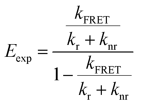
To determine the geometries that are most consistent with the experimentally determined FRET efficiencies (Eexp), we constructed heatmaps showing the absolute difference between Etheo and Eexp (Fig. S16g–i†). For these heatmaps, Eexp was calculated using eqn (5)
 | (5) |
The heatmaps for |Etheo − Eexp| were then projected onto the spherical sections and the results are shown in Fig. 8b and S16g–i.† The lower portions of the spheres were omitted (x < 5 Å) because it is assumed that due to steric constraints, PX is unable to adopt geometries that would place the 3,5-di-tert-butylbenzene groups deep within the ZrO2-A-Zn sublayers.
For the A-Zn-P1 bilayer, there is a broad range of possible geometries that show agreement between calculated and experimental values (|Etheo − Eexp| < 0.01). In contrast, for bilayers containing P2 (Fig. S16h†) and P3 (Fig. 8b), there is an apparent radial band across the sphere indicating that those structures exhibit stronger agreement between Etheo and Eexp. Among the possible geometries we selected example structures that show the best theoretical–experimental agreement, and those structures are depicted in Fig. 8c for ZrO2-A-Zn-P3 with the remaining structures in Fig. S16.†
Conclusions
Here we prepare metal ion-linked bilayer films containing a series of platinum porphyrin derivatives with one (P1), two (P2), or three (P3) phenylene spacers between the chromophoric core and the metal ion binding carboxylate group. The porphyrins were bound to a phosphonated anthracene (A) functionalized mesoporous ZrO2 surface with a Zn(II) linking ion to generate the ZrO2-A-Zn-PX bilayer films. Both time-resolved emission and transient absorption measurements indicate that the rate and efficiency of A* to PX FRET generally decrease in the order of P1 ≥ P2 >P3. With the FRET efficiency in hand, our goal was to use known parameters in the FRET equation (i.e., overlap integral, refractive index, and fluorescence quantum yield of the donor), combined with a systematic change in rDA with phenylene spacer length, to calculate the orientation factor (κ2) across the series. This method assumes that κ2 is the same for all three bilayers. However, UV-Vis polarized visible attenuated total reflectance (p-ATR) indicate that the tilt angle of the porphyrin relative to surface normal increases in the order of P3 (22°) < P2 (36°) < P1 (50°). Consequently, the interchromophore distance and orientation are changing with each bilayer and thus the method described above cannot be used to determine κ2 across the series.Furthermore, p-ATR only provides information regarding the orientation of the porphyrin plane relative to the surface normal which greatly expands the possible orientations of the long axis of the molecule relative to A. To narrow the scope of possible structures, we performed geometric calculations of all possible structures that agree with the angles determined by p-ATR and determined the theoretical FRET efficiency of each geometry. Then by comparing calculated and experimental efficiencies we proposed the most likely structures of the bilayer films.
Additionally, we compared the energy transfer rate of A-Zn-P3 bilayers on mesoporous and planar ZrO2 substrates. The nearly identical energy transfer rate indicates that the structure of the bilayer is similar, regardless of the nature of the underlying substrate. This observation is critical in that, after decades of assuming the structures are the same, this report provides strong evidence that the structure is consistent on planar and mesoporous substrates, and each can serve as a reasonable surrogate for the other.
In summary, while we were unable to determine an absolute structure, this work provides new structural insights into multilayer films on planar and mesoporous surfaces. Additionally, we demonstrate the promise of p-ATR and FRET as complementary techniques to determine the structure of multichromophore assemblies. Going forward, the use of an acceptor chromophore with a linear transition dipole moment (i.e., not a porphyrin) will dramatically narrow the possible range of structures and will enable the determination of a single, likely structure of the bilayer assembly. Furthermore, with these tools in hand, we look forward to investigating the role of variables like metal ion binding motif, surface coverage, linking metal ion, etc. in dictating the structure of these multilayer assemblies. With increased insights, one can envision controlling such structures to design assemblies that facilitate or hinder energy and electron transfer processes, for example, as desired for a given application.
Data availability
The data supporting this article have been included as part of the ESI.†Conflicts of interest
There are no conflicts to declare.Acknowledgements
Energy transfer measurements were supported by the National Science Foundation under Grant No. DMR-2327754. Characterization of the bilayer formation was supported by the Army Research Office under Grant No. W911NF-19-1-0357. A. I. is grateful to the National Science Foundation (CHE-2102579) for the support of fundamental research. A. A. acknowledges the Arnold O. Beckman Postdoctoral Fellowship Program. C. R. acknowledges support from Fonds de recherche du Québec – Nature et technologies scholarships. Some of the ATR data were acquired in the W. M. Keck Center for Nano-Scale Imaging in the Department of Chemistry and Biochemistry at the University of Arizona. This instrument was supported as part of the Center for Interface Science: Solar-Electric Materials (CIS: SEM), an Energy Frontier Research Center funded by the U.S. Department of Energy, Office of Science, Office of Basic Energy Sciences under Award No. DE-SC0001084.References
- S. P. Pujari, L. Scheres, A. T. M. Marcelis and H. Zuilhof, Angew. Chem., Int. Ed., 2014, 53, 6322–6356 CrossRef CAS.
- E. Galoppini, Coord. Chem. Rev., 2004, 248, 1283–1297 CrossRef CAS.
- A. Arcidiacono, B. Hanks and K. Hanson, ACS Appl. Opt. Mater., 2023, 1, 1156–1168 CrossRef CAS.
- J. C. Wang, S. P. Hill, T. Dilbeck, O. O. Ogunsolu, T. Banerjee and K. Hanson, Chem. Soc. Rev., 2018, 47, 104–148 RSC.
- Y. Zhou, C. Ruchlin, A. J. Robb and K. Hanson, ACS Energy Lett., 2019, 4, 1458–1463 CrossRef CAS.
- S. P. Hill, T. Dilbeck, E. Baduell and K. Hanson, ACS Energy Lett., 2016, 1, 3–8 CrossRef CAS.
- D. Beery, T. W. Schmidt and K. Hanson, ACS Appl. Mater. Interfaces, 2021, 13, 32601–32605 CrossRef CAS.
- O. O. Ogunsolu, I. A. Murphy, J. C. Wang, A. Das and K. Hanson, ACS Appl. Mater. Interfaces, 2016, 8, 28633–28640 CrossRef CAS.
- X. Ding, Y. Gao, L. Zhang, Z. Yu, J. Liu and L. Sun, ACS Catal., 2014, 4, 2347–2350 CrossRef CAS.
- N. Yoshimura, M. Yoshida, M. Kato and A. Kobayashi, Inorg. Chem., 2022, 61, 11095–11102 CrossRef CAS.
- M. A. Gross, C. E. Creissen, K. L. Orchard and E. Reisner, Chem. Sci., 2016, 7, 5537–5546 RSC.
- O. O. Ogunsolu, J. C. Wang and K. Hanson, ACS Appl. Mater. Interfaces, 2015, 7, 27730–27734 CrossRef CAS.
- J. C. Wang, I. A. Murphy and K. Hanson, J. Phys. Chem. C, 2015, 119, 3502–3508 CrossRef CAS.
- B. H. Farnum, K.-R. Wee and T. J. Meyer, Nat. Chem., 2016, 8, 845–852 CrossRef CAS.
- R. N. Sampaio, L. Troian-Gautier and G. J. Meyer, Angew. Chem., 2018, 130, 15616–15620 CrossRef.
- Z.-J. Li, C.-J. Yao and Y.-W. Zhong, Sci. China: Chem., 2019, 62, 1675–1685 CrossRef CAS.
- A. Arcidiacono, A. J. Robb, R. A. Masitas, S. R. Salpage, G. M. McLeod, J. Chen, O. O. Ogunsolu, M. G. Roper and K. Hanson, J. Photochem. Photobiol., 2022, 9, 100088 CrossRef CAS.
- K. Hanson, D. A. Torelli, A. K. Vannucci, M. K. Brennaman, H. Luo, L. Alibabaei, W. Song, D. L. Ashford, M. R. Norris, C. R. K. Glasson, J. J. Concepcion and T. J. Meyer, Angew. Chem., Int. Ed., 2012, 51, 12782–12785 CrossRef CAS.
- A. J. Robb, D. Miles, S. R. Salpage, N. Watson, Q. He, Q. Wu and K. Hanson, ACS Appl. Mater. Interfaces, 2020, 12, 38003–38011 CrossRef CAS.
- B. Tosco, B. P.-A. V. Melo, D. Hermida Merino, J. F. Q. Rey and S. Brochsztain, Langmuir, 2021, 37, 2494–2502 CrossRef CAS.
- H. C. Yang, K. Aoki, H. G. Hong, D. D. Sackett, M. F. Arendt, S. L. Yau, C. M. Bell and T. E. Mallouk, J. Am. Chem. Soc., 1993, 115, 11855–11862 CrossRef CAS.
- H. Byrd, J. L. Snover and M. E. Thompson, Langmuir, 1995, 11, 4449–4453 CrossRef CAS.
- D. Pattadar, L. Zheng, A. J. Robb, D. Beery, W. Yang, K. Hanson and S. S. Saavedra, J. Phys. Chem. C, 2023, 127, 2705–2715 CrossRef CAS PubMed.
- A. Arcidiacono, Y. Zhou, W. Zhang, J. O. Ellison, S. Ayad, E. S. Knorr, A. N. Peters, L. Zheng, W. Yang, S. S. Saavedra and K. Hanson, J. Phys. Chem. C, 2020, 124, 23597–23610 CrossRef CAS PubMed.
- D. Pattadar, A. Arcidiacono, D. Beery, K. Hanson and S. S. Saavedra, Langmuir, 2023, 39, 10670–10679 CrossRef CAS.
- M. J. Griffith, M. James, G. Triani, P. Wagner, G. G. Wallace and D. L. Officer, Langmuir, 2011, 27, 12944–12950 CrossRef CAS.
- M. Gliboff, L. Sang, K. M. Knesting, M. C. Schalnat, A. Mudalige, E. L. Ratcliff, H. Li, A. K. Sigdel, A. J. Giordano, J. J. Berry, D. Nordlund, G. T. Seidler, J.-L. Brédas, S. R. Marder, J. E. Pemberton and D. S. Ginger, Langmuir, 2013, 29, 2166–2174 CrossRef CAS PubMed.
- L. Sang, A. Mudalige, A. K. Sigdel, A. J. Giordano, S. R. Marder, J. J. Berry and J. E. Pemberton, Langmuir, 2015, 31, 5603–5613 CrossRef CAS PubMed.
- A. J. Robb, E. S. Knorr, N. Watson and K. Hanson, J. Photochem. Photobiol., A, 2020, 390, 112291 CrossRef CAS.
- W. J. Doherty, C. L. Donley, N. R. Armstrong and S. S. Saavedra, Appl. Spectrosc., 2002, 56, 920–927 CrossRef CAS.
- S. B. Mendes, J. T. Bradshaw and S. S. Saavedra, Appl. Opt., 2004, 43, 70–78 CrossRef CAS PubMed.
- T. Dilbeck, J. C. Wang, Y. Zhou, A. Olsson, M. Sykora and K. Hanson, J. Phys. Chem. C, 2017, 121, 19690–19698 CrossRef CAS.
- Y. Zhou, S. Ayad, C. Ruchlin, V. Posey, S. P. Hill, Q. Wu and K. Hanson, Phys. Chem. Chem. Phys., 2018, 20, 20513–20524 RSC.
- L. Stryer and R. P. Haugland, Proc. Natl. Acad. Sci. U. S. A., 1967, 58, 719–726 CrossRef CAS.
- Th. Förster, Ann. Phys., 1948, 437, 55–75 CrossRef.
- J. R. Lakowicz, Principles of Fluorescence Spectroscopy, Springer Science & Business Media, 2013 Search PubMed.
- V. Gray, B. Küçüköz, F. Edhborg, M. Abrahamsson, K. Moth-Poulsen and B. Albinsson, Phys. Chem. Chem. Phys., 2018, 20, 7549–7558 RSC.
- V. Gray, K. Börjesson, D. Dzebo, M. Abrahamsson, B. Albinsson and K. Moth-Poulsen, J. Phys. Chem. C, 2016, 120, 19018–19026 CrossRef CAS.
- S.-H. A. Lee, N. M. Abrams, P. G. Hoertz, G. D. Barber, L. I. Halaoui and T. E. Mallouk, J. Phys. Chem. B, 2008, 112, 14415–14421 CrossRef CAS PubMed.
- S. P. Hill, T. Banerjee, T. Dilbeck and K. Hanson, J. Phys. Chem. Lett., 2015, 6, 4510–4517 CrossRef CAS PubMed.
- G. M. McLeod, J. Nolder, A. Arcidiacono, S. Lindbom, N. Dos Santos, E. Lambert, S. Ayad, D. Beery, I. Alabugin and K. Hanson, J. Phys. Chem. C, 2024 DOI:10.1021/acs.jpcc.4c04033.
- Y. Zheng, A. J. Giordano, R. C. Shallcross, S. R. Fleming, S. Barlow, N. R. Armstrong, S. R. Marder and S. S. Saavedra, J. Phys. Chem. C, 2016, 120, 20040–20048 CrossRef CAS.
- B. Norden, G. Lindblom and I. Jonas, J. Phys. Chem., 1977, 81, 2086–2093 CrossRef CAS.
- S. P. Hill and K. Hanson, J. Am. Chem. Soc., 2017, 139, 10988–10991 CrossRef CAS PubMed.
- P. Bharmoria, H. Bildirir and K. Moth-Poulsen, Chem. Soc. Rev., 2020, 49, 6529–6554 RSC.
- Y. Zhou, S. P. Hill and K. Hanson, J. Photonics Energy, 2017, 8, 022004 Search PubMed.
- J. S. Lindsey, Acc. Chem. Res., 2010, 43, 300–311 CrossRef CAS PubMed.
- P. Mishra, J. P. Hill, S. Vijayaraghavan, W. V. Rossom, S. Yoshizawa, M. Grisolia, J. Echeverria, T. Ono, K. Ariga, T. Nakayama, C. Joachim and T. Uchihashi, Nano Lett., 2015, 15, 4793–4798 CrossRef CAS PubMed.
- M. Gouterman, J. Mol. Spectrosc., 1961, 6, 138–163 CrossRef CAS.
- R. Katoh, A. Furube, T. Yoshihara, K. Hara, G. Fujihashi, S. Takano, S. Murata, H. Arakawa and M. Tachiya, J. Phys. Chem. B, 2004, 108, 4818–4822 CrossRef CAS.
- J. R. Durrant, S. A. Haque and E. Palomares, Coord. Chem. Rev., 2004, 248, 1247–1257 CrossRef CAS.
- Y. Venkatesh, M. Venkatesan, B. Ramakrishna and P. R. Bangal, J. Phys. Chem. B, 2016, 120, 9410–9421 CrossRef CAS PubMed.
- S. M. Aly, S. Goswami, Q. A. Alsulami, K. S. Schanze and O. F. Mohammed, J. Phys. Chem. Lett., 2014, 5, 3386–3390 CrossRef CAS PubMed.
- D. L. Dexter, J. Chem. Phys., 1953, 21, 836–850 CrossRef CAS.
- H. S. Judeikis and S. Siegel, J. Chem. Phys., 1970, 53, 3500–3506 CrossRef CAS.
- J. K. Roy and M. A. El-Sayed, J. Chem. Phys., 1964, 40, 3442–3443 CrossRef CAS.
- K. B. Eisenthal, J. Chem. Phys., 1969, 50, 3120–3122 CrossRef CAS.
- V. Kaliginedi, H. Ozawa, A. Kuzume, S. Maharajan, I. V. Pobelov, N. Hee Kwon, M. Mohos, P. Broekmann, K. M. Fromm, M. Haga and T. Wandlowski, Nanoscale, 2015, 7, 17685–17692 RSC.
- H. E. Katz, W. L. Wilson and G. Scheller, J. Am. Chem. Soc., 1994, 116, 6636–6640 CrossRef CAS.
- L. E. Oquendo, R. Ehamparam, N. R. Armstrong, S. S. Saavedra and D. V. McGrath, J. Phys. Chem. C, 2019, 123, 6970–6980 CrossRef CAS.
- R. Ehamparam, L. E. Oquendo, M. W. Liao, A. K. Brynnel, K.-L. Ou, N. R. Armstrong, D. V. McGrath and S. S. Saavedra, ACS Appl. Mater. Interfaces, 2017, 9, 29213–29223 CrossRef CAS PubMed.
- P. L. Edmiston, J. E. Lee, S.-S. Cheng and S. S. Saavedra, J. Am. Chem. Soc., 1997, 119, 560–570 CrossRef CAS.
- H. Inoue, T. Hoshi, T. Masamoto, J. Shiraishi and Y. Tanizaki, Ber. Bunsenges. Phys. Chem., 1971, 75, 441–446 CrossRef CAS.
- J. A. Shelnutt and V. Ortiz, J. Phys. Chem., 1985, 89, 4733–4739 CrossRef CAS.
- S. S. Saavedra and W. M. Reichert, Anal. Chem., 1990, 62, 2251–2256 CrossRef CAS PubMed.
- J. Mårtensson, Chem. Phys. Lett., 1994, 229, 449–456 CrossRef.
Footnote |
| † Electronic supplementary information (ESI) available. See DOI: https://doi.org/10.1039/d4ta05156d |
| This journal is © The Royal Society of Chemistry 2024 |