 Open Access Article
The role of PAT in the development of telescoped continuous flow processes
Aoife M.
Kearney
 a,
Stuart G.
Collins
 *b and
Anita R.
Maguire
 *c
*c
aSchool of Chemistry, Analytical and Biological Chemistry Research Facility, University College Cork, Ireland
bSchool of Chemistry, Analytical and Biological Chemistry Research Facility, SSPC, The SFI Research Centre for Pharmaceuticals, University College Cork, Ireland. E-mail: stuart.collins@ucc.ie
cSchool of Chemistry and School of Pharmacy, Analytical and Biological Chemistry Research Facility, SSPC, The SFI Research Centre for Pharmaceuticals, University College Cork, Ireland. E-mail: a.maguire@ucc.ie
First published on 14th March 2024
Abstract
This review highlights the advantages of incorporating Process Analytical Technologies into continuous flow processes, especially in the context of telescoped multistep flow sequences. Use of FlowIR, in-line UV-vis, online HPLC, online MS and Flow NMR are discussed within this review, with multiple PAT techniques used in conjunction with one another in some instances. PAT is key in ensuring as much information as possible can be gathered during a chemical transformation, with real-time analysis allowing for rapid reaction optimization.
1.1
![[P with combining low line]](https://www.rsc.org/images/entities/h3_b_char_0050_0332.gif) rocess
rocess ![[A with combining low line]](https://www.rsc.org/images/entities/h3_b_char_0041_0332.gif) nalytical
nalytical ![[T with combining low line]](https://www.rsc.org/images/entities/h3_b_char_0054_0332.gif) echnology (PAT)
echnology (PAT)
This review will discuss the use of PAT within telescoped processes exclusively and the role PAT played in developing and facilitating these processes. Moreover, this review will discuss the role emerging techniques such as benchtop NMR spectroscopy and FlowNMR spectroscopy are playing in the reaction monitoring, particularly in the context of continuous flow processes.
1.1.1 What is PAT?
Process Analytical Technology1–4 (to be referred to as PAT from now on) is an overarching term that describes various analytical technologies and equipment designed to allow researchers to analyse and control manufacturing practices in real-time by measurement of key process parameters or critical process parameters (CPPs). PAT has become increasingly important in recent years due to the ever-growing area of continuous flow chemistry or continuous manufacturing; a system where reagents are being continuously being fed into a system while product is being collected at the outflow.5 While batch reactions will continue to be widely employed, continuous flow processes are becoming increasingly prevalent due to the flexibility that they offer, along with the smaller footprint flow reactors occupy in a typical plant or lab space.6 In most instances, especially in industrial settings, a hybrid approach is adopted which combines the benefits and advantages of both batch and continuous flow in the manufacture of products, where appropriate.Recognising the role that continuous manufacturing is playing in manufacturing of APIs, the US Food and Drug Administration (USFDA) and European Medicine Association have encouraged pharmaceutical companies to develop new manufacturing methods which incorporate a quality-by-design approach (QbD), which is reinforced using PAT.5 QbD was first developed by Juran, who championed that quality should be designed into the route to a product as early as its initial discovery, as many quality issues can be related back to the design of the particular product itself.7,8 Since its inception, many pharmaceutical companies, and indeed academic researchers, have developed new and improved synthetic routes using this QbD approach.9–17 PAT is a method for continuous monitoring of chemical processes—compared to traditional single-batch verification used to analyse a complete batch of API—with the overall aim of minimising batch-to-batch variability and/or batch failures.5,6
There are various techniques that fall under the banner of PAT: spectroscopy (IR, Raman, UV-vis, NMR), spectrometry (MS, LC-MS), and chromatography (HPLC, UHPLC, LC-MS). These methods will be discussed in further detail in the subsequent sections; however, it is critical to understand the types of sampling required for each analytical technique, especially in the context of continuous flow chemistry i.e. in-line, off-line, online sample and at-line. Many techniques can be ‘destructive’ meaning the sample cannot return to the reaction stream (MS, LC-MS or HPLC), or ‘non-destructive’ where probes inserted into the reagent line can deliver real-time analysis (IR, Raman) or a reaction sample can be diverted and subsequently re-introduced to the reaction stream post-analysis (NMR).5
1.1.2 Various sampling techniques
It is important to understand the difference between ‘destructive’ and ‘non-destructive’ sampling techniques when looking to incorporate PAT technology into a continuous flow process. Furthermore, it is crucial to recognise the difference in the sampling methods of each piece of analytical equipment. Various sampling methods are listed below:1–6,18• ![[I with combining low line]](https://www.rsc.org/images/entities/char_0049_0332.gif)
![[n with combining low line]](https://www.rsc.org/images/entities/char_006e_0332.gif) -line: this sampling technique involves analytical methods capable of recording rapid or relatively fast measurements such as an in-line IR spectroscopy probe. It involves a flow-through cell or a submerged detection probe within the cell that is placed in-line with the flow of material through the system. The benefits of this technology is that material does not need to be diverted from the reaction stream nor does this technique compromise the reaction materials, it is non-destructive by nature.
-line: this sampling technique involves analytical methods capable of recording rapid or relatively fast measurements such as an in-line IR spectroscopy probe. It involves a flow-through cell or a submerged detection probe within the cell that is placed in-line with the flow of material through the system. The benefits of this technology is that material does not need to be diverted from the reaction stream nor does this technique compromise the reaction materials, it is non-destructive by nature.
• ![[O with combining low line]](https://www.rsc.org/images/entities/char_004f_0332.gif)
![[n with combining low line]](https://www.rsc.org/images/entities/char_006e_0332.gif) -line: in a similar manner to in-line PAT, this technique involves the use of detection probes that are in continuous contact with the reagent stream. It differs from in-line sampling in that a portion of the reagent stream is diverted from the main flow path to conduct the measurement; the detection device is not in-line with the flow of material through the system. It is also a non-destructive technique, with the analysed material returned to the reaction stream post-measurement. Considerations need to be made for the flow rate and pressure of the reaction stream as the sample being diverted may not be compatible with the sampling technique being employed. For example, some FlowIR devices involve a sample being pumped to and from the window of the device that records the measurement, and, if the flow rate of the material is too high, leaking at the window may occur.
-line: in a similar manner to in-line PAT, this technique involves the use of detection probes that are in continuous contact with the reagent stream. It differs from in-line sampling in that a portion of the reagent stream is diverted from the main flow path to conduct the measurement; the detection device is not in-line with the flow of material through the system. It is also a non-destructive technique, with the analysed material returned to the reaction stream post-measurement. Considerations need to be made for the flow rate and pressure of the reaction stream as the sample being diverted may not be compatible with the sampling technique being employed. For example, some FlowIR devices involve a sample being pumped to and from the window of the device that records the measurement, and, if the flow rate of the material is too high, leaking at the window may occur.
• ![[A with combining low line]](https://www.rsc.org/images/entities/char_0041_0332.gif)
![[t with combining low line]](https://www.rsc.org/images/entities/char_0074_0332.gif) -line: this is the first analytical technique to be described in this review where a sample is removed from the reagent stream and analysed at a separate analyser unit. This technique typically uses destructive sampling methods where sample preparation is involved e.g., HPLC. The most common analytical techniques that fall into this category would be Mass Spectrometry (MS), Liquid Chromatography (LC), Gas Chromatography (GC) etc. The frequency of samples is usually much lower when using this technique as a physical sample is removed from the system, thereby reducing the overall reactor volume.
-line: this is the first analytical technique to be described in this review where a sample is removed from the reagent stream and analysed at a separate analyser unit. This technique typically uses destructive sampling methods where sample preparation is involved e.g., HPLC. The most common analytical techniques that fall into this category would be Mass Spectrometry (MS), Liquid Chromatography (LC), Gas Chromatography (GC) etc. The frequency of samples is usually much lower when using this technique as a physical sample is removed from the system, thereby reducing the overall reactor volume.
• ![[O with combining low line]](https://www.rsc.org/images/entities/char_004f_0332.gif)
![[f with combining low line]](https://www.rsc.org/images/entities/char_0066_0332.gif)
![[f with combining low line]](https://www.rsc.org/images/entities/char_0066_0332.gif) -line: while a useful method, off-line sampling methods involve the removal of a sample from the process and transport of the sample, often to a laboratory at a different location, for full analysis. While the information gained from this approach can be very insightful and should not be discounted entirely, the process is longer and not automated, meaning reaction/process insight is not being received in real-time. This would be a disadvantage if a chemist needed to make any adjustments to the process as the delay in analysing the sample would prevent real-time intervention, if required.
-line: while a useful method, off-line sampling methods involve the removal of a sample from the process and transport of the sample, often to a laboratory at a different location, for full analysis. While the information gained from this approach can be very insightful and should not be discounted entirely, the process is longer and not automated, meaning reaction/process insight is not being received in real-time. This would be a disadvantage if a chemist needed to make any adjustments to the process as the delay in analysing the sample would prevent real-time intervention, if required.
1.1.3 The use of PAT in continuous manufacturing both in industry and academia
As discussed previously, PAT has been increasingly employed by both industry and academia in recent times to monitor chemical reactions in real-time with clear benefits provided by these techniques. This review will discuss the role of PAT in enabling telescoping of continuous flow processes; an operation where a number of reactions are performed consecutively in the same linear stream.19 There have been many extensive reviews over the last number of years detailing the incorporation of PAT into manufacturing processes for the synthesis of active pharmaceutical ingredients (APIs),20–25 to facilitate in-line purification and work-up techniques,26 in advancing quality and sustainability,27 and in the development of self-optimising processes in continuous flow.28,29 Some reviews have focussed on certain aspects of the technologies such as in situ sensors for flow reactors30 and also challenges and advantages associated with the use of PAT in both industry and academic settings.31,32 This review aims to further build on these reports.1.2 The use of PAT in enabling telescoped continuous flow processes
This section will focus mainly on the use of IR and Raman spectroscopy as PATs in telescoped continuous flow processes. However, the illustrative examples included, in many instances, also involve the use of UV-Vis, HPLC/UHPLC, MS and NMR techniques incorporated into flow systems to deliver a streamlined telescoped reaction sequence.1.2.1 Use of IR and Raman spectroscopy in enabling reaction telescoping in continuous flow
There are many FlowIR devices available, with one being shown below in Fig. 1.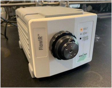 | ||
| Fig. 1 Image of a FlowIR device that can be incorporated into a telescoped continuous flow sequence. | ||
The use of IR spectroscopy in continuous flow has been around for many years with reports dating back to 2001,33 with the incorporation of a FTIR analyser to monitor the formation of cationic intermediates in a ‘cation flow’ system prior to reaction with a range of carbon nucleophiles (Scheme 1). The FTIR spectrometer was equipped with a low temperature flow cell outside the electrochemical reactor to analyse the reaction stream in real-time. In the example shown in Scheme 1, it was found that an increase in the wavenumber of the intermediate 1 when compared to the starting material 2 indicated the formation of a positively charged cation.
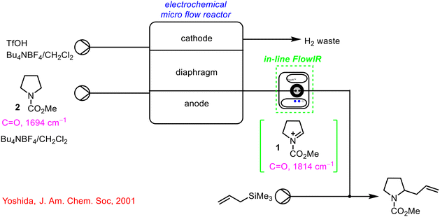 | ||
| Scheme 1 Early report of the use of FlowIR device in a telescoped continuous process by Yoshida.33 | ||
In 2009, Jähnisch and co-workers incorporated a miniaturised ATR sensor into a telescoped flow sequence involving the ozonolysis of a double bond followed by a reduction step.34 The steps were first optimised individually, with the use of online FTIR analysis allowing safe telescoping and optimal control of the entire process. This work also involved off-line HPLC analysis (destructive sampling), with samples taken from the reaction stream post-FTIR analysis, but not returned post-analysis.
Gaunt and co-workers described a newly developed FlowIR flow cell in 2010 and integrated it into a number of different reaction sequences to probe its benefits in optimising and controlling chemical transformations.35 In one instance, the FlowIR flow cell was used to analyse a Curtius rearrangement (Scheme 2). This reaction involved the generation of a highly reactive acyl azide intermediate 3 which rearranges to an isocyanate 4in situ; this isocyanate 4 readily reacts with the available nucleophile to form the desired carbamate product 5. By positioning the FlowIR flow cell between both reactor coils, monitoring of the generation of the acyl azide intermediate 3 in reactor 1 at 40 °C was possible, followed by re-positioning of the flow cell after reactor 2 to confirm the successful generation of the carbamate product 5. The integration of this technology into the system allowed accurate determination of the temperature at which the hazardous intermediate 3 was formed and was stable, so that an optimised reaction sequence could be designed.
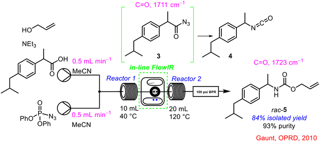 | ||
| Scheme 2 In-line FTIR analysis of carbamate 5 synthesis reported by Gaunt and co-workers.35 | ||
An example of the incorporation of in-line FlowIR analysis to aid in telescoping the continuous flow synthesis of an API was reported by the Ley group in 2010 (Scheme 3).36 The synthesis of the highly selective δ-opioid receptor agonist 6 first developed by AstraZeneca was optimised for a continuous flow platform with real-time FlowIR analysis used to control one of the input flow streams. During the initial telescoping, there were issues surrounding the introduction of the fourth reagent stream which carried Burgess reagent 7 for the dehydration step. A FlowIR 45 m flow cell was integrated into the system at this point to monitor the production of the intermediate 8 required for this transformation. As soon as the desired intermediate 8 was detected, the fourth reagent stream was initiated, ensuring efficient mixing of the reagents. It was also possible to calculate the concentration of the intermediate in the reagent stream, which in turn could be used to calculate the exact volume and concentration of Burgess reagent 7 required to carry out the dehydration step. The full telescoping of this sequence was enabled by the use of PAT.
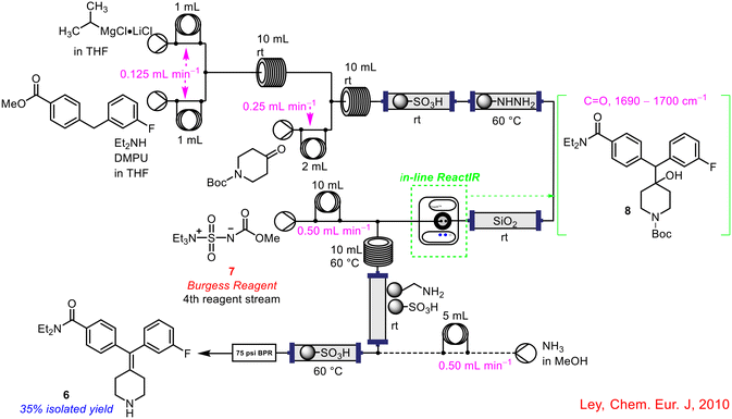 | ||
| Scheme 3 Use of in-line FlowIR flow cell in the synthesis of a δ-opioid receptor agonist 6 by Ley and co-workers.36 | ||
In a subsequent publication in 2011, the Ley group incorporated two separate FlowIR flow cells into a telescoped continuous flow process to precisely control the addition of reagent streams during the operation, with added automation to alter the amount of reagent being delivered in real-time, depending on the concentration of the various intermediates generated (Scheme 4).37 The telescoped process involved the initial formation of an ynone 9 from an acid chloride 10 and a terminal alkene 11, followed by a cyclisation using a hydrazine derivative 12 in ethanol. The original reported method used the colour of the ynone 9 stream as a gauge to commence the third pump containing the hydrazine 12.38 As this was a somewhat inefficient method, leading to large excesses of hydrazine 12 being employed (5–10 eq. vs. 1.1 eq. in batch), the addition of two in-line FlowIR flow cells greatly improved not only the productivity but the safety profile of the overall process by reducing the levels of toxic hydrazine 12 in the system. The formation of the ynone 9 was captured by the first FlowIR flow cell, which in turn triggered the initiation of the hydrazine 12 reagent stream. The feedback control ensured just 1.5 eq. of hydrazine 12 was employed as it proved efficient to effect the transformation. The second FlowIR flow cell was then used to detect the formation of the final cyclised product 13 in the exit stream post in-line purification using a number of scavengers. The final product 13 was isolated in a 69% yield following the 2-step telescoped reaction sequence in flow. To demonstrate the applicability of the methodology, the group also conducted a 2-step telescoped reduction crotylation reaction in flow with success.
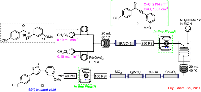 | ||
| Scheme 4 FlowIR to enhance production and safety of telescoped process by Ley and co-workers.37 | ||
In a similar manner, Ley and co-workers have also showcased the benefits of integrating FlowIR flow cells in telescoped continuous processes such as the preparation of functionalised Grignard reagents via LiCl-mediated halogen/Mg exchange followed by coupling with various carbonyl compounds (Fig. 2, a), with in-line IR spectroscopy used to monitor Grignard formation.39 In another example, a FlowIR probe was positioned post-acid chloride formation and prior to amide coupling step in flow to monitor the formation of the initial phosgene reagent which allowed accurate injection of the subsequent reagent stream to enable the final transformation in the synthesis of meclinertant (Fig. 2, b).40 Other natural products synthesised include the telescoped continuous flow synthesis of spirodienal A and spirodienal A methyl ester, each incorporating in-line FTIR analysis (Fig. 2, c).41 Ley and co-workers have also successfully employed an in-line FlowIR cell to monitor the formation of ketene intermediates in the telescoped synthesis of β-lactam derivatives in flow (Fig. 2, d).42 In all instances, the use of PAT was integral to the telescoping of the continuous flow processes described, as it allowed real-time monitoring of intermediate reagent streams to accurately calculate when to initiate subsequent reagent additions and the concentration of those reagents that was required (Fig. 2).
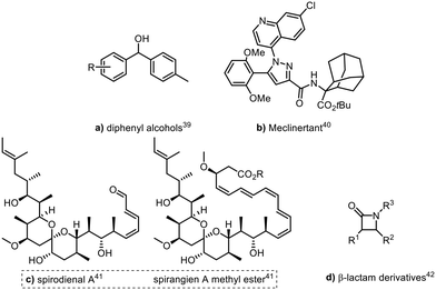 | ||
| Fig. 2 Products generated using FlowIR reaction monitoring by Ley.39–42 | ||
Another effective use of in-line FTIR analysis was described by Rutjes and co-workers to control the Vilsmeier-Haack formylation of electron-rich arenes (Scheme 5).43 A flow chemistry approach to the process was adopted to avoid handling hazardous chemicals or the reactive intermediate (Vilsmeier-Haack reagent 14) generated.44 The process involved the initial generation of the Vilsmeier-Haack reagent 14 followed by formylation of pyrrole 15. It was found that complete conversion of the POCl316 starting material was required, otherwise, the reactor would become blocked upon telescoping as the unreacted POCl316 would readily react with pyrrole 15 to form polymers. Incorporation of an in-line FlowIR flow cell allowed researchers to determine the time for full conversion of POCl316 corresponding to formation of the Vilsmeier-Haack reagent 14 to be 90 s, meaning initiation of the pyrrole 15 reagent stream could commence at this point.
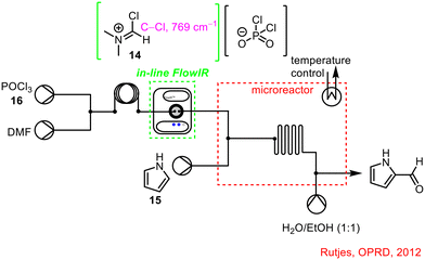 | ||
| Scheme 5 In-line FlowIR flow cell used to monitor conversion of POCl316 in the telescoped process to synthesise 2-formylpyrrole 17 (ref. 43). | ||
Ley, in collaboration with Pfizer, demonstrated once again the benefits of integrating FlowIR into the telescoped 2-step synthesis of pyrazine-2-carboxamide 18, a component of the API Rifater® 19 used to treat tuberculosis.45 The FlowIR cell was placed after the initial hydrolysis step to monitor the formation of the primary amide intermediate 19 (Scheme 6), with automatic material collection once full conversion was observed. This material was held in a reservoir until the required volume was collected, prior to commencement of the pyrazine ring reduction step. Without in-line PAT technology, off-line work-up and analysis would be required to determine the efficiency of the hydrolysis step before any subsequent steps could be conducted, making FlowIR an invaluable tool in this instance.
 | ||
| Scheme 6 Telescoped synthesis of pyrazine-2-carboxamide 18 from 19 using FlowIR.45 | ||
In 2015, work by GSK highlighted a number of key risks associated with the synthesis of oligonucleotides in continuous flow, including errors from mechanical or other unknown sources during the synthesis.10 Mechanical errors include leaks, malfunctioning valves or pumps and chemical degradation of seals within the system, while other errors include connecting the wrong reagent line to an inlet port or incorrect stock solution preparation. The implemented process was different from a typical telescoped reaction sequence as it was conducted in cycles with all reactions occurring in a single packed column. The mid-IR flow cell was integrated at the outflow of the column prior to recycling and was successfully employed to track and monitor the progress of the reaction through the cycles. Each cycle adds a new nucleotide to the chain and any errors within the process could be easily seen by a variation in the IR spectral trends recorded in real-time throughout the process. An in-line Raman spectroscopy probe was placed after the FlowIR cell for further process monitoring.
FlowIR was integrated into a seven-step, semi-continuous telescoped reaction sequence to synthesise 2-aminoadamantane-2-carboxylic acid 20, beginning with an initial Grignard step, by the Ley group in 2014 (Scheme 7).46 The formation of the Grignard reagent 21 was monitored by in-line FlowIR and subjected to an in-line quench and computer-controlled liquid–liquid separation once an acceptable conversion had been achieved. The material underwent a solvent-swap before being forward processed to the subsequent stages of the processes. The use of the in-line FlowIR cell negated the need to handle the Grignard reagent 21, as real-time monitoring of the reaction allowed the chemist to observe when full conversion had been reached and the in-line quench could commence.
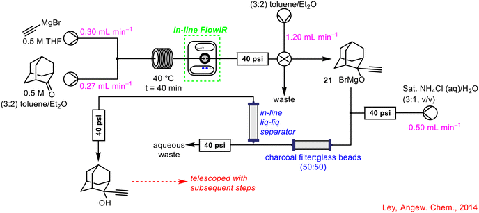 | ||
| Scheme 7 Initial Grignard step monitored by in-line FlowIR as part of a seven-step telescoped flow sequence.46 | ||
Wirth's research team described an approach to milnacipran analogues from diazo compounds in continuous flow, using in-line FlowIR as PAT to monitor the initial diazo transfer step (Scheme 8).47
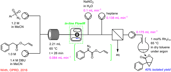 | ||
| Scheme 8 Use of in-line FlowIR to monitor diazo transfer reaction in telescoped synthesis of lactones.47 | ||
In-line FlowIR was incorporated into the four-step telescoped conversion of anilines to pyrazoles with great success (Scheme 9).48 The telescoped sequence involved a diazotization followed by a reduction, hydrolysis and co-condensation stage with the final two stages occurring in a single reactor coil. The FlowIR was incorporated following the reduction step, and prior to the introduction of the dione 22 and HCl for the final hydrolysis/co-condensation steps, serving two functions: to monitor the formation of the desired intermediate 23 and to control the flow rate of the pump introducing the dione 22 and HCl for the final stage so as to align the stoichiometries and deliver a uniform concentration profile. Once again, the use of in-line PAT not only enabled telescoping, but also minimised operator exposure to hazardous intermediates such as unreacted diazonium compounds.
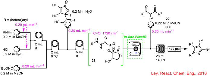 | ||
| Scheme 9 In-line FlowIR used to develop the four-step telescoped continuous synthesis of pyrazoles.48 | ||
Monbaliu and co-workers published a two-step telescoped free nucleophilic carbene generation with the NHC-catalysed benchmark transesterification of vinyl acetate 24 with benzyl alcohol 25, aided by in-line IR reaction monitoring post reaction, telescoped further with an in-line quench system (Scheme 10).49 The use of the in-line FlowIR was critical in monitoring the disappearance of the characteristic bands of vinyl acetate 24 and benzyl alcohol 25 and the formation of the signals associated with the benzyl acetate product 26, and acetaldehyde 27 as a by-product. In this instance, the FlowIR cell was not integrated between two synthetic steps but enabled the telescoping of the reagent stream from the reactor outflow with a downstream in-line quench/extraction/separation process, once again highlighting the versatility of PAT in adapting to the requirements of various chemical processes in flow.
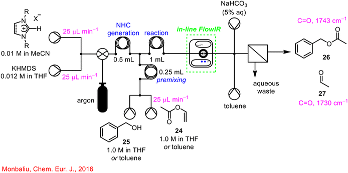 | ||
| Scheme 10 Telescoped NHC-generation with transesterification reaction.49 | ||
In 2017, the use of PAT, and specifically in-line FlowIR technology was used by Bader and co-workers in the telescoped asymmetric propargylation using allene gas 28 (Scheme 11).50 This process involved consecutive allene dissolution, lithiation, Li–Zn transmetallation and asymmetric propargylation steps in flow with the in-line FlowIR cell used to monitor the formation of the chiral allenylzinc complex 29. Interestingly, through use of the PAT technology, the previously reported instability of allenyllithium species 30 was confirmed,51,52 with a recorded half-life of 5 min at 22 °C, while the IR data collected also demonstrated that over-lithiation is indeed a reversible process. The integration of real-time process monitoring enabled safe telescoping of consecutive chemical reactions as the formation of unstable intermediates could be monitored directly, with intervention possible if required during the process.
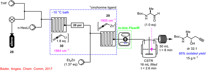 | ||
| Scheme 11 Use of in-line FlowIR in the telescoped synthesis of homopropargyl β-amino alcohols.50 | ||
The use of PAT in the form of FlowIR and FlowNMR (see section 1.2.5 for FlowNMR) was implemented successfully in the sustainable use of trifluoromethane 31 for efficient synthesis of fluorinated compounds in continuous flow (Scheme 12).53 The generation of the trifluoromethyl carbanion intermediate 32 from the first step was telescoped with the downstream generation of functionalised fluorinated compounds using chlorosilanes, among other reagents. FlowIR was utilised to monitor the concentration of trifluoromethane 31 in solution which was critical for selectivity in the products formed from the reaction. A lower dosing of trifluoromethane relative to benzophenone and base resulted in a reduced yield of product and increased side-product formation.
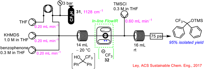 | ||
| Scheme 12 Reaction monitoring using FlowIR of the use of trifluoromethane 31 to generated functionalised fluorinated compounds in a telescoped flow process.53 | ||
Ley and co-workers developed the use of oxadiazolines as useful precursors for the formation of unstable diazo compounds using UV photolysis in continuous flow and used these derivatives in protoboronic and oxidative C(sp2)–C(sp3) cross-coupling reactions (Scheme 13).54 In one example, 4-chloroboronic acid 33 was coupled with cyclobutane oxadiazoline 34 to generate a tertiary boronic acid 35. An in-line FlowIR cell was used to monitor the formation of product 35 (by tracking the disappearance of the characteristic diazo stretch of the diazo formed from cyclobutane oxadiazoline 34), which was trapped out using pinacol to give the Bpin product 36 in 74% yield, which was subsequently telescoped with an iridium-catalysed photoredox reaction in flow, using 1-isoquinoline 37 as a coupling partner, to generate a cyclobutylated isoquinoline derivative 38.
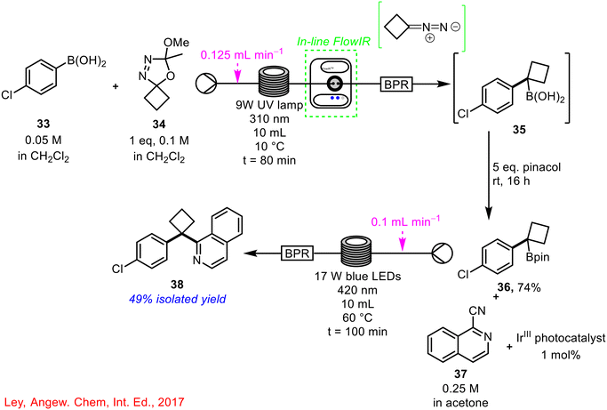 | ||
| Scheme 13 Synthesis of cyclobutylated isoquinoline compound 38 in a two-step telescoped reaction sequence using in-line FlowIR to monitor the formation of boronic acid 35 (ref. 54). | ||
In 2018, Kiil and co-workers demonstrated the successful re-design of a batch process for continuous flow towards the synthesis of Melitracen HCl 39 (Scheme 14).9 In-line PAT in the form of FlowIR was implemented to monitor conversion in real-time of the initial Grignard reaction step. This was done by tracking the distinctive carbonyl peak of 10,10-DMA 40, with its disappearance indicating complete consumption. This step was then telescoped with hydrolysis and dehydration steps, followed by phase separation and crystallisation.
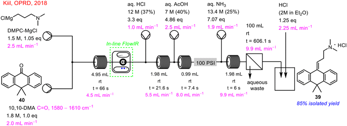 | ||
| Scheme 14 In-line FlowIR in the telescoped flow synthesis of Melitracen HCl 39 (ref. 9). | ||
In-line FlowIR cells can also be used in conjunction with other PAT sources as reported by Kappe and co-workers in 2019 where FlowIR, FlowNMR, and online UPLC were employed in a multistep organometallic transformation (Scheme 15).11 The use of FlowNMR and online UPLC will be discussed in more detail in subsequent sections but for now, the use of in-line FlowIR for the real-time monitoring of the deprotonation step of this process will be discussed. The first step of the transformation involves irreversible deprotonation using LDA to form the enolate intermediate 41. This step was easily monitored by in-line FlowIR by the disappearance of the characteristic carbonyl stretch of the propionate starting material 42 and the emergence of the band corresponding to the enolate intermediate 41. Following, steady-state enolate 41 formation, initiation of the electrophile 43 stream resulted in the disappearance of the enolate species 41. Following reaction with 43, there were no other visible carbonyl peaks present in the solution, confirming that lithium enolate 41 had indeed formed as opposed to the lithium alkoxide.
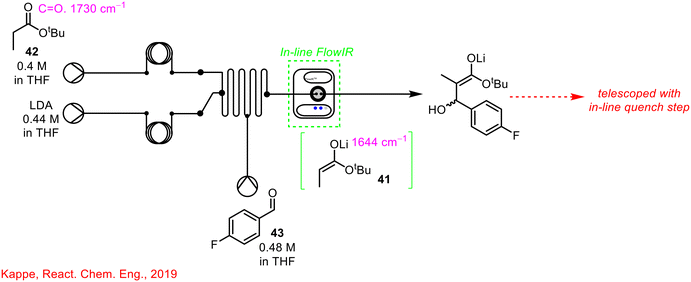 | ||
| Scheme 15 Simplified schematic of in-line FlowIR cell used by Kappe and co-workers for organolithium transformation.11 | ||
Kappe and his team built on this work and in 2021 reported the multistep synthesis of 5-ASA mesalazine in continuous flow using various PAT techniques; in-line FlowNMR, in-line UV/Vis, on-line UHPLC and relevant to this section, in-line FlowIR (see Scheme 16 below).17 The in-line FlowIR cell was used to monitor the hydrogenation reaction involving the reduction of the nitro group of 5-NSA to the corresponding amine of the desired product. The work into the continuous flow synthesis of mesalazine using PAT equipment was developed further in two subsequent publications in 2021 (ref. 16) and 2023.55
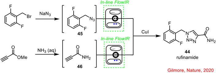 | ||
| Scheme 16 Continuous flow synthesis of rufinamide using in-line IR reported by Gilmore and co-workers.56 | ||
Gilmore and co-workers developed an automated synthesis platform using a radial synthesis concept, with individual accessible reactors around a central switching station.56 In this set-up, multistep sequences are performed as a sequential series of continuous processes, to optimise and improve the way small molecules are developed and synthesised. In one example, the radial synthesiser was used to synthesise the anticonvulsant drug rufinamide 44, with in-line FlowIR used to monitor the formation of azide 45 and amide 46, prior to the final 1,3-dipolar cycloaddition to form the final product 44 (Scheme 16).
Within the Maguire–Collins research group, in-line FlowIR capabilities have been implanted in the telescoped continuous flow synthesis of α-sulfenyl lactam products.57 The telescoped 3-step process involved the in situ generation of triflyl azide 47, followed by diazo transfer to activated lactams using DBU as base, and subsequent rhodium-catalysed S–H insertion reaction to generate the α-sulfenyl lactam products. In-line FlowIR was integrated at two points, to monitor the diazo transfer reaction (point A, Scheme 17) and the S–H insertion reaction (point B, Scheme 17). α-Diazocarbonyl compounds offer a distinct advantage in terms of monitoring due to their characteristic strong bands at 2000–2100 cm−1 (using a gold IR cell, this region is a blind window in a diamond IR cell), in a clear region of the spectrum, uncomplicated by other absorptions. The final S–H insertion reaction was monitored by tracking the disappearance of the α-diazocarbonyl stretch. An added safety feature of the use of this PAT is that it can be used to ensure that all of the hazardous triflyl azide 47 formed in the initial step has been consumed and has not been brought forward during the process. Triflyl azide 47 is present as a distinct band at 2100 cm−1 and was never observed beyond the diazo transfer step in the telescoped process. In the event of its detection, appropriate action could be taken in real-time to shut-down the generation of this hazardous intermediate.
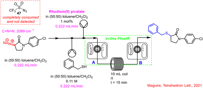 | ||
| Scheme 17 Incorporation of an in-line FlowIR cell post-diazo transfer reaction and post-S–H insertion reaction by Maguire and co-workers.57 | ||
Miyai et al. implemented PAT for the real-time monitoring of an intermediate and API concentrations using in-line FlowIR and Raman spectroscopy in the synthesis of ciprofloxacin 48; FlowIR was employed in the initial 3-step telescoped sequence with Raman spectroscopy integrated into the outflow of the subsequent 2-step telescoped process (Scheme 18).13 The in-line FlowIR cell was used to monitor the formation of cyclopropyl-enamine 49, from the amine substitution reaction of a keto-ester 50 with cyclopropylamine 51. The authors highlighted that, as this was a room-temperature reaction, it was ideal for in-line reaction monitoring by IR spectroscopy as the technique is quite temperature-dependent, as noted by Gaunt and co-workers in a previous report.35 By building a concentration model—using three calibration samples: crude solutions from step 2, isolated samples of cyclopropyl-enamine 49 in acetonitrile and isolated samples of cyclopropyl-enamine 49 diluted in crude solutions from step 2—the concentration of cyclopropyl-enamine 49 in solution during the reaction could be predicted.
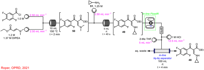 | ||
| Scheme 18 Use of FlowIR to monitor concentration of cyclopropyl-enamine 49 reported by Miyai et al.13 | ||
More recently, in 2022, Jensen and co-workers demonstrated the powerful use of FlowIR in the continuous flow synthesis of sonidegib 52, involving 3 reaction steps: nitro reduction, activation, and amide coupling (Scheme 19).58 Two separate in-line FlowIR cells were used to track the progress of the reduction and activation steps, which were occurring simultaneously. This was critical to the process as it was the products from both reactions that subsequently underwent the amide coupling reaction to deliver the final product sonidegib 52. Without real-time reaction monitoring for reaction completion in these individual processes, the subsequent telescoping would have been inefficient.
 | ||
| Scheme 19 Schematic of flow synthesis of sonidegib 52 (ref. 58). | ||
It is clear from the examples outlined above that incorporating PAT in the form of in-line FlowIR spectroscopy can be key to the successful telescoping of multistep processes, both in research laboratories and in industrial settings. As further advancements have been made both in the use of continuous flow chemistry and in the developments of multiple PAT instruments, in-line FlowIR has been shown to be used effectively alongside complementary techniques such as in-line UV-vis, online HPLC/UPLC and FlowNMR, which will each be discussed in subsequent sections.
1.2.2 Use of UV-vis spectroscopy in enabling reaction telescoping in continuous flow
Herein, attention turns to the use of UV-vis spectroscopy (Fig. 3) and its role in enabling reaction telescoping in continuous flow.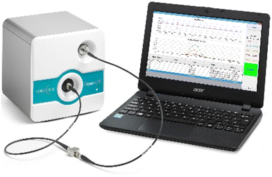 | ||
| Fig. 3 Image of in-line UV-vis spectrometer by Uniqsis® used in continuous flow (reproduced with permission). | ||
One of the earliest reports of the use of in-line UV-vis spectroscopy as a PAT tool in flow was described by Tranmer in 2006 in the synthesis of a neolignane grossamide 53 (Scheme 20).59 The in-line UV-vis spectrophotometer was integrated into the continuous system following the initial step involving the reaction of an activated ester with an amine coupling partner to generate an amide adduct 54. The group added a solvent marker between each sample being delivered to the system, which acted as triggering signals for automated fraction collection using the in-line UV-vis spectrophotometer.
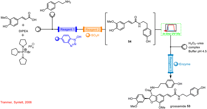 | ||
| Scheme 20 Use of in-line UV-vis reported by Tranmer in the synthesis of grossamide 53 (ref. 59). | ||
As outlined in the previous section, Kappe and co-workers incorporated in-line FlowIR spectroscopy into the telescoped flow synthesis of the sodium carboxylate salt of the API 5-ASA mesalazine 55,17 with follow-up publications further developing and discussing the synthesis (Scheme 21).16,55 FlowIR was not the sole technique used to monitor this process in real-time; an in-line UV-vis spectrometer was used for monitoring the third step of the process to form the di-sodium salt of 5-NSA 56. This PAT technique tracked the concentration of the precursor from the previous step (5N-2CIBA 57) and the product 56, giving an indication of conversion for the reaction. As the product from this step was telescoped with the final hydrogenation step to give the final mesalazine sodium carboxylate salt product 55, real-time monitoring of the formation of 56 was key to ensuring full conversion prior to hydrogenation.
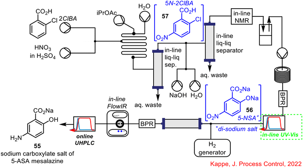 | ||
| Scheme 21 Telescoped synthesis of sodium carboxylate salt of mesalazine reported by Kappe.16,17,55 | ||
In 2010, Ley and co-workers described the flow-based synthesis of Imatinib 58, the API of Gleevec used for the treatment of chronic leukaemia, where an in-line UV sensor was integrated into the telescoped reaction sequence (Scheme 22).60 The synthesis involved the initial construction of the amide core via reaction between an acid chloride 59 and aniline 60, this was followed by an SN2 displacement of the chloride in the amide with N-methylpiperazine 61, and a Buchwald–Hartwig coupling of the generated intermediate with a pyrimidim-2-amine 62 to form the final product 58.
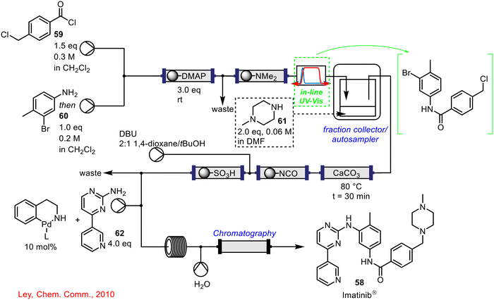 | ||
| Scheme 22 Telescoped continuous flow synthesis of imatinib 58 incorporating in-line UV-vis spectroscopy to monitor product dispersion following step 1 (amide formation).60 | ||
The telescoping of the initial amide formation and nucleophilic substitution step proved difficult, and it was decided to place an in-line UV-vis spectrophotometer between the steps. The real-time UV-vis data indicated significant product dispersion in the outflow from the amide formation with the concentration of material changing with time. To avoid having to use an excess of N-methylpiperazine 61, an autosampler was connected with the UV-vis spectrometer and was set to collect material at a certain absorbance threshold, ensuring the highest concentrated fraction was collected and forward processed to the nucleophilic substitution step. PAT in the form of a UV-vis spectrophotometer, facilitated the telescoping of this system, providing the real-time data which ensured that two stoichiometrically equivalent streams met one another for efficient reaction to take place.
In 2014, Barton and co-workers demonstrated the use of in-line PAT in an end-to-end continuous pharmaceutical pilot plant process.12 The process began with an advanced intermediate and finished with tablet formulation steps. The in-line PAT was utilized as a process control to keep critical attributes close to the desired set points for an extended time during the process. In particular, in-line UV-vis spectroscopy was integrated into the complex system via feed-back control loops to adjust the ratios of feed pumps to deliver the desired concentration of reagents in solution, and feed-forward control loops to alter the flow ratios of feed pumps to adjust dosage to account for disturbances in flow rate and concentration of intermediates. The use of in-line PAT in this instance proved integral to the complete automation of the pilot plant process.
Gioiello and co-workers have described a continuous flow process for the synthesis of 16-dehydropregnenolone 63 (16-DPA) from the cheap, and readily available diosgenin 64 (Scheme 23).61 16-DPA is a key substrate in the production of several natural steroids and drugs and the synthesis is comprised of an initial acetylation/acetolysis step followed by oxidative cleavage and a final hydrolysis/elimination step. In-line UV-vis spectroscopy was used in two ways; initially, it was used in the development of the individual reaction steps in flow to monitor the crude reaction mixtures. In terms of parameter screening, the UV-vis system was used as a tool to track reaction completion i.e. when no further UV signals for starting materials/intermediates could be detected, the reaction was complete, and accordingly, a new set of conditions could be trialled. Following optimisation of the individual reaction steps, the final telescoped reaction sequence employed an in-line UV-vis spectrophotometer to monitor the formation of the desired product 64, prior to forward-processing to the downstream processes, which included in-line work-up and purification. Without the aid of PAT, the reaction outflow could not be monitored for reaction completion in real-time. This work was built on in 2020 with a further publication on the synthesis of neurosteroid 3-β-methoxypregnenolone, once again demonstrating the use of in-line UV-vis spectroscopy in the synthesis of this API.62
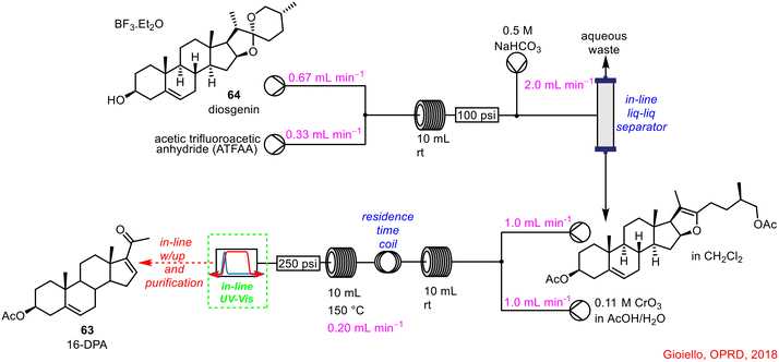 | ||
| Scheme 23 Telescoped flow synthesis of 16-DPA using in-line UV-vis spectroscopy to monitor reaction completion.61 | ||
In 2019, Kappe and co-workers developed a convenient method for monitoring reagent concentration using in-line UV-vis spectrometry in the generation, purification and quantification of nitrosyl chloride 65 telescoped with the well-known photochemical synthesis of cyclohexanone oxime 66 from cyclohexane 67, via radical photonitrosation of cyclohexane 67,63 all in continuous flow (Scheme 24).64 The in-line UV-vis spectrophotometer was placed just after the in-line liquid–liquid separator following the nitrosyl chloride 65 generation, to monitor reagent concentration, prior to telescoping with the downstream photochemical reaction. Nitrosyl chloride 65 is rarely used in laboratory settings due to its hazardous nature.65,66 The use of flow chemistry and in-line PAT techniques in the form of UV-vis spectroscopy, not only allows this chemical to be generated safely in situ, but also to be employed in subsequent useful transformations via reaction telescoping without handling or isolation of the hazardous intermediate.
 | ||
| Scheme 24 Telescoped NOCl 65 generation with photochemical synthesis of cyclohexanone oxime 66 using in-line UV-vis spectrometry to monitor NOCl 65 concentration.64 | ||
Recently, an example of the use of in-line UV-vis spectrometry as PAT from Kappe and co-workers was published, in collaboration with Roche (Scheme 25).67,68 A new route towards the cannabinoid receptor type 2 agonist, RG7774 68, was developed using a combination of batch and continuous flow processing, containing a total of seven reaction steps. Of relevance to this review was the use of in-line UV-vis spectrometry as a PAT tool for the monitoring of the outflow, containing 69, from an intermediate amine scavenging treatment, which was telescoped with the final nucleophilic aromatic substitution step in flow.
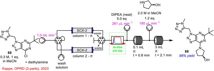 | ||
| Scheme 25 Telescoped amine scavenging with nucleophilic aromatic substitution in flow using in-line UV-vis spectrometry developed by Kappe and co-workers.67,68 | ||
During the initial experiments for the direct nucleophilic aromatic substitution to form the triazole product 68, there was a side-product present (up to 10% area by HPLC analysis), identified as the product formed from the reaction of the chloro-triazole starting material with diethylamine (brought forward from previous steps). As this was undesirable, a scavenger step was implemented prior to the final step to remove any traces of diethylamine from the reagent stream. This was carried out using an acid-functionalised silica treatment; two cartridges were employed so that while one column was treating the reagent stream, the second column could be regenerated via treatment with HCl (2 M) leading to no instrument downtime. The in-line UV-vis ensured that diethylamine was effectively scavenged, with the stream diverted to a fresh column, when required. This made sure that no diethylamine was introduced to the final reaction stage and the nucleophilic aromatic substitution step could proceed as normal. The optimised process gave the desired triazole product 68 in 98% yield, with less than 0.5% of the undesired diethylamine derived side-product present; a significant process improvement on the previous method which generated up to 10% of this material. The work of Kappe and Roche is a perfect example of how in-line PAT techniques can be critical to ensuring the effective telescoping of chemical processes in flow, leading to overall process improvements.
1.2.3 Use of online HPLC/UHPLC in enabling reaction telescoping in continuous flow
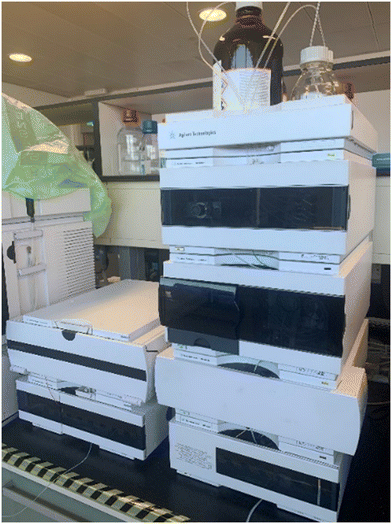
While discussion up to now in terms of spectroscopy focussed predominantly on in-line monitoring, PAT using HPLC/UHPLC (HPLC shown below in Fig. 4) requires online reaction sampling, with a portion of the reagent stream diverted from the main flow path to conduct the measurement; the majority of the reaction material is returned to the main reagent stream post-analysis.In an early example, Eli Lilly reported the development of a commercial Barbier process—combination of an organic halide, organic electrophile and a metal to generate coupled products—for a pharmaceutical intermediate in continuous flow (Scheme 26).14 Within the flow process itself, PAT was employed to assist the process development, intended to support the aforementioned Quality by Design approach (see section 1.1.1) for a regulatory submission. Online HPLC as a process monitoring tool was incorporated at two points within the process, following the Barbier–Grignard reaction and post-carbonate wash. The conversion in the CSTR could be easily tracked by HPLC through the decrease in starting material 70 and increase in the portion of product 71 present.
 | ||
| Scheme 26 Barbier process developed by Eli Lilly in continuous flow.14 | ||
While the Kappe research group has utilized various PAT techniques in their continuous flow work such as FlowIR and UV-vis spectroscopy discussed above, in many instances, online HPLC/UHPLC has been used alongside these techniques for process monitoring. In the case of the previously described organolithium transformation, online UHPLC was placed after the in-line FlowIR cell for real-time reaction analysis (see Scheme 15 for reaction details).17 Online UHPLC was also used to provide a detailed overview of the final reaction composition in the synthesis of mesalazine 55 (refer to Scheme 20 for process details).16,17,55
Bourne and co-workers developed an automated continuous flow system for self-optimisation of chemical reactions.69 A part of this work included the design of a multipoint sampling unit using an online HPLC for accurate reaction monitoring of a Heck cyclisation-deprotection reaction sequence. It was thought that a single self-optimising system was of more benefit than optimising individual reaction steps and subsequently telescoping them, and perhaps encountering further hurdles. HPLC was chosen as the analytical tool in this instance due to its widespread use in the pharmaceutical industry as well as its ability to easily quantify complex reaction mixtures. The incorporation of the online HPLC into the telescoped reaction sequence is shown below in Scheme 27.
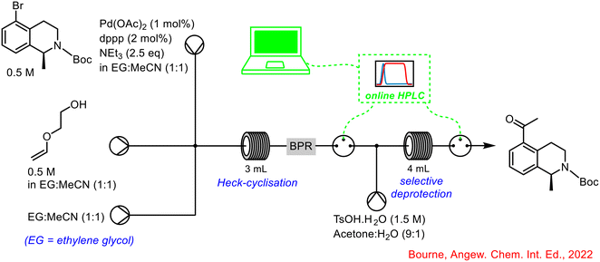 | ||
| Scheme 27 Integration of online HPLC into self-optimising telescoped reaction by Bourne.69 | ||
By-integrating the online HPLC at two points in the system, both reaction steps could be monitored individually, and interventions made, if necessary, based on the real-time feedback from the computer software program processing the HPLC data. The authors concluded that multipoint sampling was critical in identifying the true mechanistic pathway of the reaction (Scheme 26), especially with the detection of the vinyl ether intermediate 72, as it was completely consumed under all subsequent hydrolysis conditions. If this was not detected it would have been assumed that the ketal 73 was the major product under optimised conditions which then led to the final product 74 following hydrolysis. Optimisation of the individual steps would have led to the optimised formation of the ketal 73, when in fact, the optimised telescoped reaction showed that the final product was formed from a mixture of both the vinyl ether 72 and ketal 73, demonstrating the importance and utility of self-optimising reaction sequences, and use of PAT in delivering successful telescoped processes (Scheme 28).
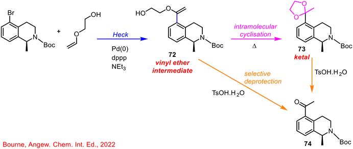 | ||
| Scheme 28 Mechanistic pathway of heck-cyclisation and final hydrolysis reaction sequence.69 | ||
1.2.4 Use of online mass spectrometry in enabling reaction telescoping in continuous flow
While MS is very powerful in structure determination, in practice, its use as an online monitoring technology lags behind that of the spectroscopies (IR, Raman, UV-vis), with one disadvantage being that traditional systems are quite large, rendering their integration into a flow system inconvenient.One example reported in 2012 where online MS was successfully employed was by Ley and co-workers, who incorporated an on-line miniature MS into the generation of benzyne 75via diazotisation of anthranilic acid 76, telescoped with an in situ cycloaddition with furan 77.70 This process differs from previously described telescoped operations in that all reagents were added initially, and two reactions occurred one after the other within the flow system, as outlined below in Scheme 29. A significant advantage of using the online PAT was that when the process was conducted with a reactor coil temperature below 50 °C, it was clear that the hazardous benzenediazonium-2-carboxylate 78, which is explosive by nature, was detected, and, accordingly, a reducing agent was added to the collection flask to mitigate this risk. Prior to online monitoring, it was assumed that all of the hazardous intermediate 78 which had been generated, had been consumed. The authors also noted some of the disadvantages of using online MS, namely that precipitates or suspensions cannot be passed through the MS device.
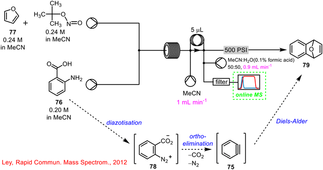 | ||
| Scheme 29 Use of online MS in telescoped synthesis of 1,4-endoxide-1,4-dihydronaphthalene 79 (ref. 70). | ||
A second example of the utility of online MS to telescoped continuous flow processes is by Cooks and co-workers from 2017, where the use of online and offline MS was described in the telescoped synthesis and subsequent purification/crystallisation of diphenylhydramine 80 (DPH), an antihistamine found in Benadryl® (Scheme 30).71 The online MS was placed after the initial DPH synthesis and prior to the crystallisation stage. It was found that at lower operating temperatures, no significant product was detected, however, increasing the reactor temperature to 150 °C and again to 200 °C resulted in a substantial increase in product formation. MS was used to determine the optimal reaction conditions for DPH formation which was then seamlessly telescoped with a downstream crystallisation process to deliver analytically pure material with no intermediate work-up or isolation steps.
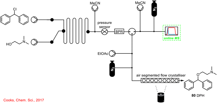 | ||
| Scheme 30 Simplified schematic of online MS used to monitor DPH 80 formation telescoped with in-line crystallisation/purification.71 | ||
Although there are not many examples of online MS used in telescoped continuous flow processes to-date, it is an ever-evolving area and with the development of miniature MS devices and more sophisticated sample preparation techniques, increased instances of the use of this beneficial PAT tool is anticipated in the future.
1.2.5 The use of in-line FlowNMR in enabling reaction telescoping in continuous flow
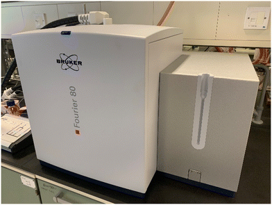
Over the last decade, FlowNMR has been used as a uniquely powerful tool for elucidating reaction mechanisms and for gaining insight into how certain chemical transformations occur. In most instances, FlowNMR has been used to study a single reaction or transformation using a FlowNMR probe and a high-field NMR spectrometer (i.e. 600 MHz for 1H NMR);72,73 what is less common is the integration of FlowNMR technology (Fig. 5, showing a Bruker Benchtop NMR machine) as a PAT tool in telescoped continuous flow processes. This section aims to highlight recent examples where FlowNMR has been successfully employed in such processes.The utility of NMR spectroscopy in monitoring a number of transient intermediates within a reaction is well established, and because it can be quantitative, it holds many advantages over the more commonly used FlowIR or Raman spectroscopic techniques. Among the many advantages of low-field benchtop NMR spectrometers is that they are lightweight and mobile, meaning they can be easily integrated into the system/process of interest. Although with low-field NMR instruments comes less sensitivity and a poorer signal-to-noise ratio, in many instances, this can be overcome by altering the data acquisition setting and/or concentration of the solution.74
Ley and co-workers developed a continuous flow process for cyclopropanation reactions using in-line benchtop NMR spectroscopy for reaction monitoring.15 In the example shown below in Scheme 31, ethyl nitroacetate 81 was reacted with styrene 82 in the presence of phenyliodine(III) diacetate 83 and catalytic amounts of Rh2(esp)284 in a cyclopropanation reaction to form 1-nitro-1-cyclo-propylcarboxylate 85. The progress of the reaction was monitored by in-line FlowNMR spectroscopy (44 MHz) prior to the crude reaction mixture being pumped through a downstream purification process using a packed column containing QP-TU 86 (thiourea), as a metal scavenger. The in-line PAT tool allowed optimisation of the process from an initial yield of 37% to 77% isolated yield of 85.
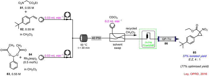 | ||
| Scheme 31 In-line FlowNMR used in continuous flow cyclopropanation reaction.15 | ||
Previously, in section 1.2.1, the work by Ley's group into the productive use of waste materials, such as trifluoromethane, in continuous flow was discussed which made use of an in-line FlowIR device (refer to Scheme 12 for full details).53 In addition to FlowIR, they also employed in-line FlowNMR spectroscopy to track the process. The in-line 43 MHz benchtop NMR was placed just after the second reactor coil to monitor the second reaction in real-time and add a further layer to the PAT tools already in place within the system (Scheme 32). This is a prime example of the use of multiple PAT technologies in conjunction with one another to gain as much insight as possible into the transformation and exploit the complementary advantages offered by each technique. For example, while IR spectroscopy is very beneficial in tracking key functional groups in some reagents/products, NMR spectroscopy is particularly beneficial in tracking key signals that may not be as distinct using IR, and vice versa.
 | ||
| Scheme 32 Use of in-line FlowNMR in conjunction with in-line FlowIR reported by Ley and co-workers.53 | ||
In 2018, a Syngenta–Cambridge collaboration described the multistep continuous flow process towards the synthesis of key building block 87 (Scheme 33), subsequently used in the formation of thiazoles.75 Within this complex telescoped reaction sequence, in-line FlowNMR was used to monitor the outflow from the reaction to form the intermediate building block 87. Interestingly, in-line FlowIR was also used in this process to monitor the final reaction step, a clear example of one or more PAT techniques being used in tandem to study different reaction steps of the same sequence in real-time. The use of continuous flow technology, as well as in-line PAT tools, was of significant importance to this work in particular, as it avoided the handling or isolation of large amounts of hazardous intermediates, ensuring no major build-up of these reagents at any one time within the system.
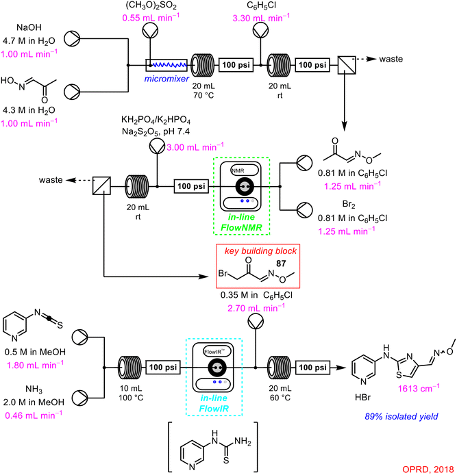 | ||
| Scheme 33 Synthesis of thiazoles in a multistep continuous flow process using in-line FlowNMR (and FlowIR) as PAT tools.75 | ||
The work of Kappe and co-workers in the development of a continuous flow synthesis of the sodium carboxylate salt of mesalazine 55 (5-ASA) has been well documented in this review.16,17,55 The complex process made use of the previously discussed in-line FlowIR, in-line UV-vis and online UHPLC to monitor the progress of the process in real-time. The final PAT tool that was incorporated was an in-line NMR spectrometer used for in situ monitoring of the initial nitration step, and the subsequent acid/base extraction (Scheme 34).
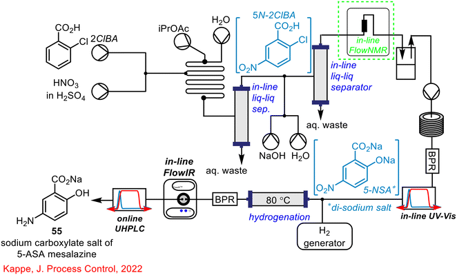 | ||
| Scheme 34 Telescoped synthesis of the sodium carboxylate salt of mesalazine 55 reported by Kappe utilising in-line FlowNMR, in-line UV-vis, in-line FlowIR and online UHPLC as process monitoring tools.16,17,55 | ||
In 2022, the Kappe research team published a self-optimising two-step telescoped synthesis of the API edaravone, involving imine 88 formation and a cyclisation step (Scheme 35).76 In-line FlowNMR spectroscopy (43 MHz) was used for in situ monitoring of the initial imine 88 formation via condensation of phenylhydrazine 89 and ketoester 90 and, as in some previous examples, a second PAT tool, in the form of in-line FlowIR, was used to monitor the outflow from the subsequent cyclisation step. A significant number (x = 85) of optimisation experiments were conducted to study seven reaction variables: equivalents of hydrazine, step one concentration, step one residence time, temperature in step one and two, equivalents of triethylamine and additional solvent in step two. Over the course of these optimisation reactions, 5.42 kg L−1 h−1 space–time yield of product edaravone 91 was achieved, with all experiments taking just 28 h, making substantial time-savings compared to a standard batch approach for optimising processes, which would require multiple individual experiments planned over days or weeks. Real-time data also indicated >95% solution yield of the imine intermediate 88. The authors highlighted one limitation; the large consumption of starting materials, with 14.3 g h−1 of the ketoester 90 employed during the study, which was required due to the time that a process takes to reach steady state.
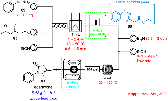 | ||
| Scheme 35 Telescoped two-step synthesis of API edavarone using in-line FlowNMR to monitor initial imine formation step.76 | ||
1.3 Conclusions
This review highlights the successful use of in-line and online PAT tools – such as FlowIR, UV-vis, HPLC/UHPLC, MS and FlowNMR – in telescoped continuous flow process and, in particular, how these tools enabled the telescoping of reaction sequences.Not only has this review covered the use of single PAT instruments in telescoped continuous flow processes, it also details examples where multiple PAT tools have been used in conjunction with one another to monitor multiple steps in a reaction sequence, to gain real-time information and mechanistic insight into what is taking place within the system, with some examples detailing self-optimising strategies employed using computer software systems. Delivering on the potential of these technologies for process control can be envisaged through embedding machine-learning and self-optimisation as recently discussed by Noël's group.77
As more complex chemistries are being adapted for continuous flow set-ups, in-line and online PAT instruments will be pivotal to the understanding of the process and in the development and optimisation of the process towards continuous flow.
Conflicts of interest
There are no conflicts to declare.Acknowledgements
The authors would like to acknowledge the Irish Research Council (IRC) (A. M. K. – GOIPG/2018/112), the HEA (COVID-19 Related Research Costed Extension to A. M. K.), the SSPC, the SFI Research Centre for Pharmaceuticals, supported by Science Foundation Ireland (SFI) and co-funded under the European Regional Development Fund (SFI SSPC2 12/RC/2275, SFI SSPC3 Pharm5 12/RC/2275_2 and SFI 15/RI/3221), for funding.References
- J. Workman, D. J. Veltkamp, S. Doherty, B. B. Anderson, K. E. Creasy, M. Koch, J. F. Tatera, A. L. Robinson, L. Bond and L. W. Burgess, Anal. Chem., 1999, 71(12), 121–180 CrossRef.
- J. Workman, M. Koch and D. J. Veltkamp, Anal. Chem., 2003, 75(12), 2859–2876 CrossRef CAS.
- J. Workman Jr., B. Lavine, R. Chrisman and M. Koch, Anal. Chem., 2011, 83(12), 4557–4578 CrossRef PubMed.
- J. B. Callis, D. L. Illman and B. R. Kowalski, Anal. Chem., 1987, 59(9), 624A–637A CrossRef CAS.
- M. A. Morin, W. Zhang, D. Mallik and M. G. Organ, Angew. Chem., 2021, 133(38), 20774–20794 CrossRef.
- G. A. Price, D. Mallik and M. G. Organ, J. Flow Chem., 2017, 7(3–4), 82–86 CrossRef CAS.
- J. M. Juran, Juran on quality by design: the new steps for planning quality into goods and services, Simon and Schuster, 1992 Search PubMed.
- L. X. Yu, G. Amidon, M. A. Khan, S. W. Hoag, J. Polli, G. Raju and J. Woodcock, AAPS J., 2014, 16, 771–783 CrossRef CAS PubMed.
- M. J. Pedersen, T. Skovby, M. J. Mealy, K. Dam-Johansen and S. Kiil, Org. Process Res. Dev., 2018, 22(2), 228–235 CrossRef CAS.
- J. W. Rydzak, D. E. White, C. Y. Airiau, J. T. Sterbenz, B. D. York, D. J. Clancy and Q. Dai, Org. Process Res. Dev., 2015, 19(1), 203–214 CrossRef CAS.
- P. Sagmeister, J. D. Williams, C. A. Hone and C. O. Kappe, React. Chem. Eng., 2019, 4(9), 1571–1578 RSC.
- R. Lakerveld, B. Benyahia, P. L. Heider, H. Zhang, A. Wolfe, C. J. Testa, S. Ogden, D. R. Hersey, S. Mascia, J. M. B. Evans, R. D. Braatz and P. I. Barton, Org. Process Res. Dev., 2015, 19(9), 1088–1100 CrossRef CAS.
- Y. Miyai, A. Formosa, C. Armstrong, B. Marquardt, L. Rogers and T. Roper, Org. Process Res. Dev., 2021, 25(12), 2707–2717 CrossRef CAS.
- T. M. Braden, M. D. Johnson, M. E. Kopach, J. McClary Groh, R. D. Spencer, J. Lewis, M. R. Heller, J. P. Schafer and J. J. Adler, Org. Process Res. Dev., 2017, 21(3), 317–326 CrossRef CAS.
- B. Ahmed-Omer, E. Sliwinski, J. P. Cerroti and S. V. Ley, Org. Process Res. Dev., 2016, 20(9), 1603–1614 CrossRef CAS.
- S. Sacher, I. Castillo, J. Rehrl, P. Sagmeister, R. Lebl, J. Kruisz, S. Celikovic, M. Sipek, J. D. Williams, D. Kirschneck and C. O. Kappe, Chem. Eng. Res. Des., 2022, 177, 493–501 CrossRef CAS.
- P. Sagmeister, R. Lebl, I. Castillo, J. Rehrl, J. Kruisz, M. Sipek, M. Horn, S. Sacher, D. Cantillo, J. D. Williams and C. O. Kappe, Angew. Chem., Int. Ed., 2021, 60(15), 8139–8148 CrossRef CAS PubMed.
- M. Rodriguez-Zubiri and F.-X. Felpin, Org. Process Res. Dev., 2022, 26(6), 1766–1793 CrossRef CAS.
- D. Webb and T. F. Jamison, Chem. Sci., 2010, 1(6), 675–680 RSC.
- C. R. Sagandira, S. Nqeketo, K. Mhlana, T. Sonti, S. Gaqa and P. Watts, React. Chem. Eng., 2022, 7(2), 214–244 RSC.
- H. Pataki, G. Marosi and L. L. Simon, Org. Process Res. Dev., 2015, 19(1), 3–62 CrossRef.
- F. F. Gouveia, J. P. Rahbek, A. R. Mortensen, M. T. Pedersen, P. M. Felizardo, R. Bro and M. J. Mealy, Anal. Bioanal. Chem., 2017, 409, 821–832 CrossRef CAS PubMed.
- P. Bana, R. Örkényi, K. Lövei, Á. Lakó, G. I. Túrós, J. Éles, F. Faigl and I. Greiner, Bioorg. Med. Chem., 2017, 25(23), 6180–6189 CrossRef CAS PubMed.
- J. Jiao, W. Nie, T. Yu, F. Yang, Q. Zhang, F. Aihemaiti, T. Yang, X. Liu, J. Wang and P. Li, Chem. – Eur. J., 2021, 27(15), 4817–4838 CrossRef CAS PubMed.
- Y. Zhang and W.-K. Su, Pharm. Front., 2023, 5(4), 209–218 CrossRef.
- Z. Fülöp, P. Szemesi, P. Bana, J. Éles and I. Greiner, React. Chem. Eng., 2020, 5(9), 1527–1555 RSC.
- D. Hebrault, A. J. Rein and B. Wittkamp, ACS Sustainable Chem. Eng., 2022, 10(16), 5072–5077 CrossRef CAS.
- V. Sans and L. Cronin, Chem. Soc. Rev., 2016, 45(8), 2032–2043 RSC.
- D. Fabry, E. Sugiono and M. Rueping, React. Chem. Eng., 2016, 1(2), 129–133 RSC.
- J. Li, H. Šimek, D. Ilioae, N. Jung, S. Bräse, H. Zappe, R. Dittmeyer and B. P. Ladewig, React. Chem. Eng., 2021, 6, 1497–1507 RSC.
- M. Baumann, Org. Biomol. Chem., 2018, 16(33), 5946–5954 RSC.
- A. Chanda, A. M. Daly, D. A. Foley, M. A. LaPack, S. Mukherjee, J. D. Orr, G. L. Reid III, D. R. Thompson and H. W. Ward, Org. Process Res. Dev., 2015, 19(1), 63–83 CrossRef CAS.
- S. Suga, M. Okajima, K. Fujiwara and J.-I. Yoshida, J. Am. Chem. Soc., 2001, 123(32), 7941–7942 CrossRef CAS PubMed.
- S. Hübner, U. Bentrup, U. Budde, K. Lovis, T. Dietrich, A. Freitag, L. Küpper and K. Jähnisch, Org. Process Res. Dev., 2009, 13(5), 952–960 CrossRef.
- C. F. Carter, H. Lange, S. V. Ley, I. R. Baxendale, B. Wittkamp, J. G. Goode and N. L. Gaunt, Org. Process Res. Dev., 2010, 14(2), 393–404 CrossRef CAS.
- Z. Qian, I. R. Baxendale and S. V. Ley, Chem. – Eur. J., 2010, 16(41), 12342–12348 CrossRef CAS PubMed.
- H. Lange, C. Carter, M. Hopkin, A. Burke, J. Goode, I. Baxendale and S. Ley, Chem. Sci., 2011, 765–769 RSC.
- I. R. Baxendale, S. C. Schou, J. Sedelmeier and S. V. Ley, Chem. – Eur. J., 2010, 16(1), 89–94 CrossRef CAS PubMed.
- T. Brodmann, P. Koos, A. Metzger, P. Knochel and S. V. Ley, Org. Process Res. Dev., 2012, 16(5), 1102–1113 CrossRef CAS.
- C. Battilocchio, B. J. Deadman, N. Nikbin, M. O. Kitching, I. R. Baxendale and S. V. Ley, Chem. – Eur. J., 2013, 19(24), 7917–7930 CrossRef CAS PubMed.
- S. Newton, C. F. Carter, C. M. Pearson, L. de C. Alves, H. Lange, P. Thansandote and S. V. Ley, Angew. Chem., 2014, 126(19), 5015–5020 CrossRef.
- A. Hafner and S. V. Ley, Synlett, 2015, 26(11), 1470–1474 CrossRef CAS.
- S. A. van den Broek, J. R. Leliveld, R. Becker, M. M. Delville, P. J. Nieuwland, K. Koch and F. P. Rutjes, Org. Process Res. Dev., 2012, 16(5), 934–938 CrossRef CAS.
- M. Bollyn, Org. Process Res. Dev., 2005, 9(6), 982–996 CrossRef CAS.
- R. J. Ingham, C. Battilocchio, J. M. Hawkins and S. V. Ley, Beilstein J. Org. Chem., 2014, 10(1), 641–652 CrossRef PubMed.
- R. J. Ingham, C. Battilocchio, D. E. Fitzpatrick, E. Sliwinski, J. M. Hawkins and S. V. Ley, Angew. Chem., 2015, 127(1), 146–150 CrossRef.
- S. T. Müller, A. Murat, P. Hellier and T. Wirth, Org. Process Res. Dev., 2016, 20(2), 495–502 CrossRef.
- J.-S. Poh, D. L. Browne and S. V. Ley, React. Chem. Eng., 2016, 1(1), 101–105 RSC.
- L. Di Marco, M. Hans, L. Delaude and J. C. M. Monbaliu, Chem. – Eur. J., 2016, 22(13), 4508–4514 CrossRef CAS PubMed.
- H. Li, J. W. Sheeran, A. M. Clausen, Y. Q. Fang, M. M. Bio and S. Bader, Angew. Chem., Int. Ed., 2017, 56(32), 9425–9429 CrossRef CAS PubMed.
- L. Brandsma and H. Verkruijsse, Synthesis of Acetylenes, Allenes, and Cumulenes, Elsevier Scientific Publishing Company, 1981 Search PubMed.
- J. M. Vatèle, Encyclopedia of Reagents for Organic Synthesis, 2001 Search PubMed.
- B. Musio, E. Gala and S. V. Ley, ACS Sustainable Chem. Eng., 2018, 6(1), 1489–1495 CrossRef CAS.
- A. Greb, J. S. Poh, S. Greed, C. Battilocchio, P. Pasau, D. C. Blakemore and S. V. Ley, Angew. Chem., Int. Ed., 2017, 56(52), 16602–16605 CrossRef CAS PubMed.
- I. Castillo, J. Rehrl, P. Sagmeister, R. Lebl, J. Kruisz, S. Celikovic, M. Sipek, D. Kirschneck, M. Horn, S. Sacher and D. Cantillo, J. Process Control, 2023, 122, 59–68 CrossRef CAS.
- S. Chatterjee, M. Guidi, P. H. Seeberger and K. Gilmore, Nature, 2020, 579(7799), 379–384 CrossRef CAS PubMed.
- A. M. Kearney, D. Lynch, S. G. Collins and A. R. Maguire, Tetrahedron Lett., 2021, 83, 153438 CrossRef CAS.
- A. M. Nambiar, C. P. Breen, T. Hart, T. Kulesza, T. F. Jamison and K. F. Jensen, ACS Cent. Sci., 2022, 8(6), 825–836 CrossRef CAS PubMed.
- I. R. Baxendale, C. M. Griffiths-Jones, S. V. Ley and G. K. Tranmer, Synlett, 2006, 2006(3), 0427–0430 CrossRef.
- M. D. Hopkin, I. R. Baxendale and S. V. Ley, Chem. Commun., 2010, 46(14), 2450–2452 RSC.
- V. Mancino, B. Cerra, A. Piccinno and A. Gioiello, Org. Process Res. Dev., 2018, 22(5), 600–607 CrossRef CAS.
- V. Mancino, F. Croci, A. M. Lozza, B. Cerra and A. Gioiello, React. Chem. Eng., 2020, 5(2), 300–307 RSC.
- M. Naylor and A. Anderson, J. Org. Chem., 1953, 18(1), 115–120 CrossRef CAS.
- R. Lebl, D. Cantillo and C. O. Kappe, React. Chem. Eng., 2019, 4(4), 738–746 RSC.
- L. Schio, C. Li, S. Monti, P. Salén, V. Yatsyna, R. Feifel, M. Alagia, R. Richter, S. Falcinelli and S. Stranges, Phys. Chem. Chem. Phys., 2015, 17(14), 9040–9048 RSC.
- J. Orphal, J. Quant. Spectrosc. Radiat. Transfer, 2019, 230, 115–119 CrossRef CAS.
- P. Sagmeister, M. Prieschl, D. Kaldre, C. Gadiyar, C. Moessner, J. Sedelmeier, J. D. Williams and C. O. Kappe, Org. Process Res. Dev., 2023, 27(4), 592–600 CrossRef CAS.
- M. Prieschl, P. Sagmeister, C. Moessner, J. Sedelmeier, J. D. Williams and C. O. Kappe, Org. Process Res. Dev., 2023, 27(4), 601–609 CrossRef CAS.
- A. D. Clayton, E. O. Pyzer-Knapp, M. Purdie, M. F. Jones, A. Barthelme, J. Pavey, N. Kapur, T. W. Chamberlain, A. J. Blacker and R. A. Bourne, Angew. Chem., 2023, 62(3), e202214511 CrossRef CAS PubMed.
- D. L. Browne, S. Wright, B. J. Deadman, S. Dunnage, I. R. Baxendale, R. M. Turner and S. V. Ley, Rapid Commun. Mass Spectrom., 2012, 26(17), 1999–2010 CrossRef CAS PubMed.
- B. P. Loren, M. Wleklinski, A. Koswara, K. Yammine, Y. Hu, Z. K. Nagy, D. H. Thompson and R. G. Cooks, Chem. Sci., 2017, 8(6), 4363–4370 RSC.
- J. Bart, A. J. Kolkman, A. J. Oosthoek-de Vries, K. Koch, P. J. Nieuwland, H. Janssen, J. van Bentum, K. A. Ampt, F. P. Rutjes and S. S. Wijmenga, J. Am. Chem. Soc., 2009, 131(14), 5014–5015 CrossRef CAS PubMed.
- D. A. Foley, E. Bez, A. Codina, K. L. Colson, M. Fey, R. Krull, D. Piroli, M. T. Zell and B. L. Marquez, Anal. Chem., 2014, 86(24), 12008–12013 CrossRef CAS PubMed.
- W. G. Lee, M. T. Zell, T. Ouchi and M. J. Milton, Magn. Reson. Chem., 2020, 58(12), 1193–1202 CrossRef CAS PubMed.
- E. Godineau, C. Battilocchio, M. Lehmann, S. V. Ley, R. Labes, L. Birnoschi, S. Subramanian, C. Prasanna, A. Gorde and M. Kalbagh, et al. , Org. Process Res. Dev., 2018, 22(8), 955–962 CrossRef CAS.
- P. Sagmeister, F. F. Ort, C. E. Jusner, D. Hebrault, T. Tampone, F. G. Buono, J. D. Williams and C. O. Kappe, Adv. Sci., 2022, 9(10), 2105547 CrossRef PubMed.
- A. Slattery, Z. Wen, P. Tenblad, J. Sanjosé-Orduna, D. Pintossi, T. den Hartog and T. Noël, Science, 2024, 383(6681), eadj1817 CrossRef CAS PubMed.
| This journal is © The Royal Society of Chemistry 2024 |

