
 Open Access Article
 This Open Access Article is licensed under a
 Creative Commons Attribution 3.0 Unported Licence
Porous carbon composites as clean energy materials with extraordinary methane storage capacity†
Ibtisam
Alali
ab,
Amina U.
Shehu
 a and
Robert
Mokaya
*a
a and
Robert
Mokaya
*a
aSchool of Chemistry, University of Nottingham, University Park, Nottingham NG7 2RD, UK. E-mail: r.mokaya@nottingham.ac.uk
bChemistry Department, College of Science, Jouf University, P.O. BOX 2014, Sakaka, Saudi Arabia
First published on 20th June 2024
Abstract
The main hurdle that is holding back the use of natural gas as a fuel for vehicles and in other forms of transportation is the lack of materials that can store sufficient amounts under accessible operating conditions to make it both viable and competitive. In this regard, the main challenge is finding materials that have the right balance of porosity and packing density, and that can store and deliver methane to the set volumetric targets. Here we report a new approach to achieving such materials by presenting the concept of carbon composites that simultaneously have high porosity (up to ca. 2800 m2 g−1 and 1.5 cm3 g−1) and high packing density (up to ca. 1.0 g cm−3). Using plastic waste as starting material, we have prepared carbon composites that are modelled on activated carbons but with an added inorganic component, and that achieve (at 25 °C) methane storage of 285 cm3 (STP) cm−3 at 35 bar, 374 cm3 (STP) cm−3 at 65 bar and 447 cm3 (STP) cm−3 at 100 bar. The carbon composites can also deliver methane of up to 256 cm3 (STP) cm−3 for a pressure swing of 35 to 1 bar, 280 cm3 (STP) cm−3 for a 65 to 5 bar pressure swing, and 358 cm3 (STP) cm−3 for a 100 to 5 bar pressure swing. This methane storage performance is greater, by some margin, than any previously reported and meets set volumetric uptake targets even at a low pressure of 35 to 65 bar. Our findings offer a new concept and insights in the much wider area of the development of porous materials for the storage of energy-related gas (CH4, H2, CO2, etc), and could offer a step change in the achievable level of volumetric storage of methane as a fuel especially for vehicular transport use.
Broader contextThis manuscript presents a new synthesis approach that yields materials that address the main bottleneck that is holding back the use of natural gas as a fuel for vehicles and in other forms of transportation, i.e. the lack of porous solids that can safely store sufficient amounts of natural gas under accessible operating conditions. The materials challenge is to find solids with the right balance of porosity and packing density, which can store and deliver methane to set volumetric targets. We present the concept of carbon composites, comprising carbon and alumina, that simultaneously have high porosity (up to ca. 2800 m2 g−1 and 1.5 cm3 g−1) and high packing density (up to ∼1 g cm−3). The carbon composites are prepared via simple activation methods for activated carbons but with a serendipitous twist in the preparation procedure, which allows the presence of alumina as a minor component. The inorganic component in the carbon composites contributes to enhanced packing density. At 25 °C, the carbon composites achieve methane storage (cm3 (STP) cm−3) of 285, 374 and 447 at 35, 65 and 100 bar, respectively. The carbon composites can also deliver large amounts of methane (cm3 (STP) cm−3) of up to 256 (35 to 1 bar swing), 280 (65 to 5 bar) and 358 for a 100 to 5 bar swing. These values represent a step change in the achievable level of methane storage, and our findings offer a new concept and insights in the much wider area of the development of materials for energy-related gas (CH4, H2, CO2, etc) storage. |
1. Introduction
The on-going use of fossil fuels means that minimizing CO2 levels in the atmosphere is regarded as one of the most significant environmental and scientific challenges.1–3 A variety of approaches can be used to reduce CO2 emissions, such as improvements in the efficiency of existing energy sources, CO2 capture and storage, or development of renewable and clean energy sources.1–4 Ideally, using renewable and cleaner fuels with lower carbon emissions is the best strategy.5 In this regard, biogas and natural gas, which mainly consist of methane (CH4), represent cleaner fuel alternatives that may be used during the transition period to non-fossil fuels or energy sources.6–9 One of the main challenge that has prevented the widespread use of natural gas as a transition fuel for vehicular transport is its low volumetric energy density under atmospheric conditions. The energy density can be improved by storing natural gas as compressed natural gas (CNG) or liquefied natural gas (LNG). However, both CNG and LNG are not competitively viable under ambient temperature and pressure, where the high cost of processes involved (cryogenics and compression) and the high safety risk complicate their use. On the other hand, storing natural gas in adsorbed form, i.e., adsorbed natural gas (ANG,) is a promising technology that can operate at low pressure and ambient temperature in a manner that can reduce costs and offer improved ease of use. The US Department of Energy (DOE) has recently set a volumetric methane storage target of 350 cm3 (STP) cm−3 and gravimetric storage capacity of 0.5 g (CH4) g−1 at room temperature and a pressure of 35 to 100 bar to enable widespread use of methane for vehicular transport. It is worth noting that the 350 cm3 (STP) cm−3 target was set at that level based on the crystallographic density of metal organic frameworks (MOFs) that are considered to be a leading class of methane storage materials. The reasoning behind this target is that MOFs have a crystallographic density that is at least 25% higher than their actual packing density. Hence, this target (350 cm3 (STP) cm−3) allows for a 25% reduction in volumetric capacity (to ca. 263 cm3 (STP) cm−3) to account for packing of MOFs inside a storage tank. Accordingly, porous adsorbents must meet the 263 cm3 (STP) cm−3 storage target to become practical storage materials for ANG technology.For viable use of methane as an energy source, especially for vehicular transport, one of the most challenging barriers is achievement of sufficient volumetric storage capacity. In this regard, the main obstacle to achieving high methane storage in solid adsorbents is finding a suitable balance between porosity (surface area, pore volume and pore size), which determines the gravimetric uptake, and the packing density that is critical for volumetric uptake. The porosity-packing density conundrum must, therefore, be resolved before MOF or carbon-based porous materials can realistically store viable amounts of methane on a volumetric basis. Sufficiently high gravimetric methane uptake can already be achieved especially for MOFs and carbons that have very high surface area.10–21 However, for MOFs, the highest surface area and porosity is accompanied by lower packing density, a combination that fails to deliver sufficient volumetric uptake.10,11,14,15,21 Attempts to address this conundrum include compaction22 or preparation of monolithic MOFs that have higher packing density.23,24 However, due to their low mechanical stability, compaction is not an entirely viable solution for MOFs as densification (i.e., increase in packing density) is usually accompanied by diminution of porosity and consequently lowering of gravimetric uptake.22,25 The synthesis of monolithic MOFs is a more recent approach that has proved more successful but suffers from low gravimetric methane uptake because monolithic MOFs tend to have low to moderate porosity.23,24 Porous carbons, on the other hand, are more amenable to densification/compaction with retention of porosity and gravimetric gas uptake.26–31 Alternative approaches have explored the use of binders to improve the packing density of porous carbons,32 or the synthesis of monolithic forms of activated carbons.33
Despite a great deal of on-going and previous research, there appears to be a limit to the packing density (and consequently volumetric gas uptake) that can be achieved by MOFs and purely carbonaceous carbons. A new synthesis approach to porous materials is therefore required if the desired target levels of methane volumetric storage are to be achieved. Here we explore a new approach that is based on the preparation of porous carbon composites consisting mainly of carbon along with some inorganic matter as a minor component. To illustrate our approach, we have used plastic waste to generate the carbon composites, which adds to the environmentally friendly credentials of the synthesis route. Plastic waste, especially polyethylene terephthalate (PET), is one of the largest and most problematic source of solid waste, meaning that the disposal of PET products is now a critical environmental issue.34–36 Whilst PET products may be recycled via mechanical approaches, chemical recycling is preferred as it adheres to ‘sustainable development’ principles,36–38 and opens up new ways of generating high-value-added carbons.39 Crucially, the carbon composites are prepared using well-established procedures for the synthesis of activated carbons but with a twist wherein an inorganic component is present during the activation step. The carbon composites still achieve porosity that is suitable for moderate to high gravimetric methane storage but more importantly, the presence of an inorganic component enhances their packing density with the consequence that they have very attractive levels of volumetric uptake. The inorganic component, which in the present case is mainly alumina, can also act to strengthen the carbon composites once they are compacted meaning that mechanically stable and robust pellets or discs with high packing density are generated with virtually no loss in porosity or gravimetric methane uptake compared to powder forms.
2. Experimental section
2.1 Material synthesis
The PET waste used as a carbon precursor was obtained from post-consumer water bottles. The bottles were cleaned to be free of impurities and dried, then cut into small pieces. The PET was first converted to hydrochar via hydrothermal carbonization (HTC) as follows: 4.6 g of PET waste was dispersed in 20 ml of deionised water and placed in a stainless-steel autoclave, which was then heated to 250 °C, maintained at 250 °C for 2 h and cooled to room temperature. The resulting carbonaceous product, the PET hydrochar (PETHC), was filtered, washed abundantly with deionised water, and dried at 100 °C for 24 h. The hydrochar was chemically activated as follows; the required KOH amount was added to the PETHC, at a KOH/PETHC mass ratio of 4, and thoroughly mixed. The resulting mixture was placed in an alumina ceramic boat and inserted inside a tubular furnace and heated at a ramp rate of 3 °C min−1 to temperatures ranging from 600 to 800 °C under a flow of nitrogen. The furnace was held at the final temperature (600, 700 or 800 °C) for 1 h, and then cooled to room temperature under a flow of nitrogen gas. The resultant activated carbon was stirred in 10% HCl at room temperature. The final activated carbons were filtered, washed abundantly with deionised water until neutral pH (pH = 7) for the filtrate was achieved, and dried in an oven at 100 °C. The resulting carbons were designated as PET4T, where 4 is the KOH/PETHC ratio and T is activation temperature in °C (600, 700 or 800). KOH/PETHC ratio of 4 was used as it yielded materials with porosity suitable for further exploration as methane stores.We also used sawdust (SD) as starting material in a synthesis procedure where a known amounts of alumina was added to the activation mix. This sought to demonstrate that any suitable starting material as source of carbon and any source of alumina (i.e., added alumina or leaching of alumina boats) can be used to prepare the activated carbon composites. The SD was sieved to obtain a homogeneous particle size (#280 nm). 4.6 g of the SD was dispersed in 20 ml of deionised water and placed in a stainless-steel autoclave, which was then heated to 250 °C, maintained at 250 °C for 2 h and cooled to room temperature. The resulting sawdust-derived hydrochar (SDH) was filtered, washed abundantly with deionised water and then dried in the oven at 100 °C. The SDH was activated as follows; 4 g of KOH was placed in an agate mortar and ground into a fine powder. 1 g of SDH was added to the powdered KOH, followed by addition of a known amount of alumina. The KOH, SDH and alumina were thoroughly mixed resulting in a black solid, which was transferred into a ceramic boat, placed into a horizontal furnace and heated up to 800 °C (at ramp rate of 3 °C min−1) and held for 1 h. After cooling to room temperature under a flow of nitrogen, the activation products were washed with 20% HCl and with deionized water until neutral pH of the filtrate was achieved. The activated carbon products were then dried in the oven and designated as SDHACCx (SDH derived activated carbon composite) where x represents the ratio of SDH to alumina in the activation mix. An activated carbon sample with no alumina added was also prepared as described above and designated as SDHAC.
2.2 Material characterisation
Elemental, CHN, analysis was performed on an Exeter Analytical CE-440 Elemental Analyser. Thermogravimetric analysis (TGA) was performed using a TA Instruments Discovery analyser or TA Instruments SDT Q600 analyser under flowing (100 mL min−1) air conditions. A PANalytical X’Pert PRO diffractometer was used to perform powder XRD analysis using Cu-Kα light source (40 kV, 40 mA) with step size of 0.02° and 50 s time step. Raman spectra were recorded using a Horiba-Jobin-Yvon LabRAM Raman microscope with a 532 nm laser operating at ca. 4 mW (10%) and a 600 lines per mm grating. Spectra were collected by averaging 8 acquisitions of 60 s duration. The Raman shift was calibrated using the Rayleigh peak and the 520.7 cm−1 Si line from a Si (100) reference sample. Nitrogen sorption analysis (at −196 °C) with a Micromeritics 3FLEX sorptometer was used for porosity analysis and to determination of textural properties. Prior to analysis the samples were degassed under vacuum at 200 °C for 16 h. Surface area was calculated using the Brunauer–Emmett–Teller (BET) method applied to adsorption data in the relative pressure (P/P0) range of 0.02–0.22. The relative pressure range was selected so as to ensure a positive y-axis intercept from multipoint BET fitting (such that C > 0) and that Vads(1 − p/p0) would increase with P/P0. The pore volume was estimated from the total nitrogen uptake at close to saturation pressure (P/P0 ≈ 0.99). The micropore surface area and micropore volume were determined via t-plot analysis. The pore size distribution (PSD) was determined using non-local density functional theory (NL-DFT) applied to nitrogen adsorption data. Scanning electron microscopy (SEM) images were recorded using an FEI Quanta200 microscope, operating at 5 kV accelerating voltage.2.3 Methane uptake measurements
Methane uptake was determined using a Hiden Isochema XEMIS Analyser. Before the uptake measurements, the carbon samples were degassed at 240 °C under vacuum for several hours. Methane uptake isotherms were obtained at 25 °C over the pressure range of 0 –100 bar. The balance of the XEMIS has an error of ±0.2 μg, a temperature error of ±0.1 °C, while the sample temperature has an error of ±0.01 to 0.1 °C.3. Results and discussion
3.1 Yield, elemental composition and nature of carbon materials
The yield and elemental composition of the PET-derived hydrochar (PETHC) and PET4T activation products are presented in Table 1. The elemental composition of the PET bottle waste used as starting material (precursor) is consistent with that of PET polymer (i.e., (C10H8O4)n). The yield of PETHC hydrochar from the PET bottle waste was 73%, which is much higher compared to other types of precursors that typically have hydrothermal carbonization yields of between 30 and 50%.40–42 As expected, the elemental C content increased following hydrothermal carbonization from 62.1% for the PET bottle waste to 67.4% for the PETHC hydrochar. Thermogravimetric analysis (TGA) confirmed that the PETHC hydrochar did not contain any inorganic matter as it was fully burnt off when heated in air as shown in Fig. 1(a). This clarifies that any inorganic components in the final PET4T activated carbon products must be introduced during the next step during which the PETHC hydrochar is activated with KOH. The yield of activated products following activation of the PETHC hydrochar with KOH is between 37 and 42% depending on the activation temperature. Considering that the hydrochar yield from PET bottle waste was 73%, this means that the overall yield of activated matter with respect to the starting PET bottle waste precursor is between 27 and 31%. Such a yield of activated carbon products is higher than for most other precursors where the yield for KOH activation ranges between 5 and 20%.40,41 The elevated yield is an early indication of the presence of denser non-carbon ingredients in the PET4T activation products. The retention of inorganic components was confirmed by the TGA curves shown in Fig. 1(a). The curves of the PET4T activated products indicate an initial mass loss below 100 °C, which is ascribed to elimination of moisture and volatiles. Sample PET4600 has a relatively higher initial mass loss, which may be related to a more hydrophilic nature arising from the presence of greater amounts of inorganic content. The main mass loss for the PET4T activation products, corresponding to carbon burn off, occurs between 550 and 650 °C, while on the other hand, the PETHC hydrochar burns off completely between 250 and 400 °C. For the PET4T activated samples, the burn off occurs in the expected temperature range for non-graphitic carbon. The residual inorganic matter for PET4T samples varies with activation temperature; 9.5% for PET4600, 8.0% for PET4700 and 7.5% for PET4800. The presence of inorganic components mean that the final activated products (hereinafter referred to as activated carbon composites) are composite materials, i.e., a mixture of carbon and some inorganic matter.| Sample | Yielda [wt%] | C [%] | H [%] | Mb [%] | Oc [%] | O/Cd ratio |
|---|---|---|---|---|---|---|
| a Yield of PETHC hydrochar is with respect to PET, while yield of PET4T is with respect to PETHC. b Estimated metal content. c Obtained as difference (i.e., 100-C–H–M). d Atomic ratio. | ||||||
| PET (bottle waste) | 62.1 | 4.1 | 33.8 | 0.41 | ||
| PETHC hydrochar | 73 | 67.4 | 3.9 | 28.7 | 0.32 | |
| PET4600 | 42 | 67.0 | 0.1 | 7.9 | 25.0 | 0.29 |
| PET4700 | 39 | 71.0 | 0.2 | 6.6 | 22.2 | 0.23 |
| PET4800 | 37 | 77.2 | 0.3 | 6.2 | 16.3 | 0.16 |
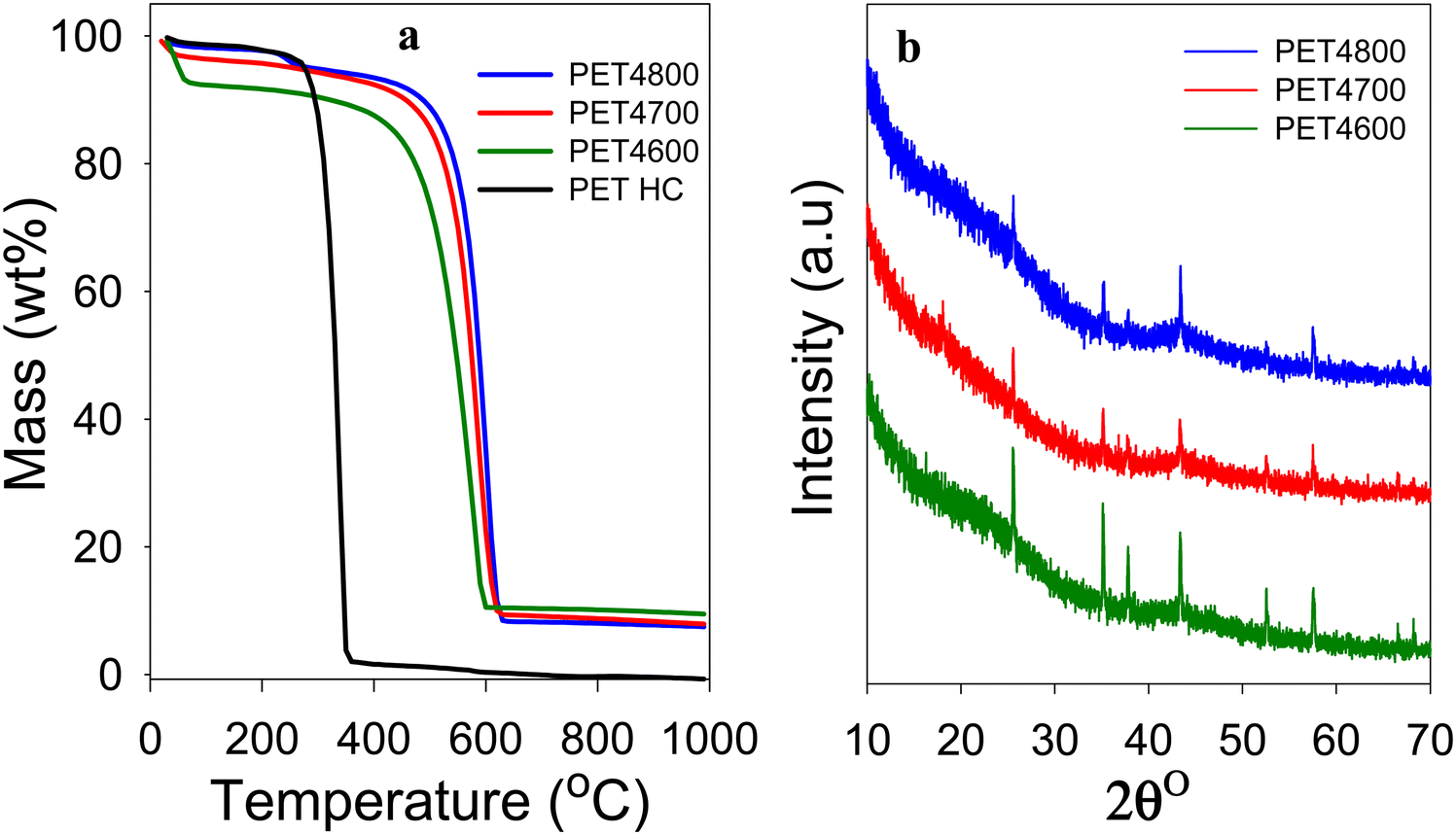 | ||
| Fig. 1 Nature of PET-derived hydrochar and activated carbon composites. (a) TGA curves of PETHC hydrochar and PET4T activated carbon composites prepared at KOH/PETHC ratio of 4, and 600–800 °C. (b) Powder XRD pattern of PET4T activated carbon composites prepared at KOH/PETHC ratio of 4, and 600–800 °C. | ||
The XRD patterns of the activated carbon composites are shown in Fig. 1(b). All the PET4T samples exhibit broad and low-intensity features at 2θ = 22° and 44°, indicating that the carbon component is amorphous (non-graphitic) in nature. The broad peaks at 2θ = 22° and 44° are nominally assigned to (002) interlayer spacing between adjacent graphite layers and (100) in-plane ordering of graphite, respectively. The XRD patterns also show sharp peaks that have a non-carbon origin and which arise from the presence of crystalline inorganic components. As stated above, given that the PETHC hydrochar was purely carbonaceous as confirmed by TGA (Fig. 1(a)), the inorganic components in the final PET4T composite materials must arise during the activation step with KOH. It is therefore necessary to consider, firstly the possible compounds that may be formed during the activation step from the reactants (i.e., PETHC hydrochar and KOH), and secondly those that may arise from other sources beyond the reactants.43–45 The reaction between KOH and the C in the hydrochar proceeds according to; 6KOH + 2C → 2K + 3H2 + 2K2CO3. At temperatures above 700 °C, K2CO3 decomposes according to; K2CO3 → K2O + CO2.43,44 Thus, the main inorganic residues from KOH are K2CO3 and K2O. For conventional activation, these K residues are washed away to generate fully carbonaceous activated carbons. The expectation that K residues are washed away is in line with the observation that the sharp XRD peaks in Fig. 1(b) are not consistent with the presence of K2O and K2CO3 only (Fig. S1, ESI†). The peaks at 2θ = 25.5°, 35.1° and 43.1° may arise from K2CO3 while that at 37.8° could be from K2O with the former being more pronounced for sample PET4600 (Fig. S1a, ESI†). This is to be expected because K2CO3 only starts to decompose to K2O at 700 °C. However, the overall trend in the intensities of the peaks at 25.5°, 35.1° and 43.1° (Fig. S1, ESI†) is not consistent with what is expected for K2CO3. Furthermore, no sharp peaks are observed in the 2θ region between 26° to 34° where peaks are expected for K2CO3 and K2O (Fig. S1a, ESI†). Thus, although the presence of K2CO3 and K2O cannot be entirely ruled out, these compounds are unlikely to constitute the main part of the inorganic component present in the activated carbon composites. On the other hand, all the sharp peaks and their intensity suggest the presence of Al2O3 (Fig. S1b, ESI†). The alumina can only be introduced during the activation step, and is then subsequently retained in the carbon composites through the washing steps as it is not soluble in HCl. The source of the alumina can only be, unexpectedly and serendipitously, from the alumina boat despite the known stability of such ceramics. To remove any ambiguity regarding the source of alumina, we ground an alumina boat to powder (designated as AB alumina) and compared its XRD pattern to those of the PET4T samples (Fig. S2, ESI†). The XRD pattern of AB alumina, and in particular the sharp peaks, are fully in line with those of the PET4T activated carbon composites. This confirms the alumina boat, via leaching, as the source of alumina.
The presence of inorganic components, chiefly alumina, is reflected in the elemental composition of the PET4T activated carbon composites (Table 1), which contain between 6 and 8 wt% of metal (M) content.46 The C content of the acyivated carbón composites increases at higher activation temperature as is usually also observed for purely carbonaceous activated carbons.40–42 It is noteworthy that the presence of the inorganic components means that the elemental O content (16–25 wt%) is higher than that typically observed for equivalent (in terms of level of activation) activated carbons, which is usually between 5- and 15 wt%. This translates to a noticeably high O/C ratio (0.16–0.29) for the present activated carbon composites as opposed to values below 0.15, which are typically observed for fully carbonaceous activated carbons.40–42
The morphology of the carbon composites is dominated by irregularly shaped particles with large conchoidal cavities and sharp edges (Fig. S3 and S4, ESI†). Such morphology is consistent with what is now accepted as being the typical particle shape for KOH-activated carbons regardless of their sources.40–43 Despite the heterogeneous nature of the carbon composites (with respect to their carbon/inorganic mix), the SEM images give the appearance of essentially one phase materials in a manner similar to fully carbonaceous activated carbons.40–43 This means that the carbon and alumina are uniformly integrated or interspersed, which is important in terms of material consistency and properties. Elemental mapping (Fig. S5–S7, ESI†) confirmed that alumina is present and that it is uniformly distributed throughout the carbon composite samples. There is also evidence of residual K, but at an apparently much lower concentration. Importantly, the elemental mapping is consistent with the TGA and XRD data in confirming the presence of inorganic components, mainly in the form of alumina. Furthermore, the XRD patterns (Fig. S1 and S2, ESI†), and in particular the intensity of the sharp peaks, suggest that the size of alumina particles in the activated carbon composites is no larger than those present in the ground alumina boat (AB alumina). This was confirmed by a combination of SEM images and elemental mapping (Fig. S8 and S9, ESI†), which showed that there are no large alumina particles. The alumina particles, in general, appear to be either of similar size or smaller than those of the carbon components (Fig. S8 and S9, ESI†).
To further ascertain the nature of the carbon in the carbon composites, we performed Raman analysis. The Raman spectra are shown in Fig. 2. The spectra show bands at 1310–1330 cm−1 and 1590–1610 cm−1, which may, respectively, be ascribed to the D-peak (disordered carbon) and the G-peak (graphitic domains).40–42 The spectra are similar to those typically observed for activated carbons.40–42 The ratio of peak intensity (i.e., area) of the D-peak to G-peak (ID/IG), based on the two-band fitting model is in line with previous reports for activated carbons. This confirms that the carbon component in the PET4T activated carbon composites is largely amorphous in a manner similar to conventional activated carbons. The Raman spectra, therefore, confirms that the presence of inorganic matter (alumina) does not alter the nature of the carbon component or its level of graphitisation.
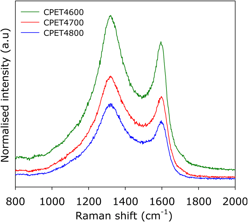 | ||
| Fig. 2 Nature of PET-derived activated carbon composites. Raman spectra of compacted CPE4T activated carbon composites. | ||
3.2 Porosity and textural properties
For use in methane storage, the as-prepared powder forms of the activated carbon composites would need to be compacted or extruded into pellets or discs. The porosity, textural properties and packing density that are most relevant to performance of the composites in methane storage are therefore those of the compacted forms. For this reason, we compacted the activated carbon composites and in discussing their porosity and packing density, we will concentrate on the compacted forms of the composites but will make relevant comparisons with as-prepared powder equivalents. The carbon composites were compacted in a 1.3 cm (diameter) die, at 370 MPa for 10 min. under ambient temperature conditions. The compacted activated carbon composites are designated as CPET4T, where C denotes compaction and T is the activation temperature (600, 700 or 800 °C). On compaction, the powder forms of the composites were converted to well-formed and mechanically robust pellets/discs (Fig. S10, ESI†). The nitrogen sorption isotherms and pore size distribution (PSD) curves of the PET-derived activate carbon composites before and after compaction are shown in Fig. 3. The isotherms indicate that the composites have a mix of microporosity and mesoporosity. Crucially, there is no change in the shape of the isotherms following compaction. The level of porosity (amount of nitrogen adsorbed) is also retained after compaction (Fig. 3(a)). The micro/mesoporous nature of the carbon composites is evidenced in the pore size distribution curves with pores of size between 5 and 35 Å with pore maxima at 7, 12 and 22 Å (Fig. 3(b)). The proportion, and size, of larger mesopores increases at higher activation temperature.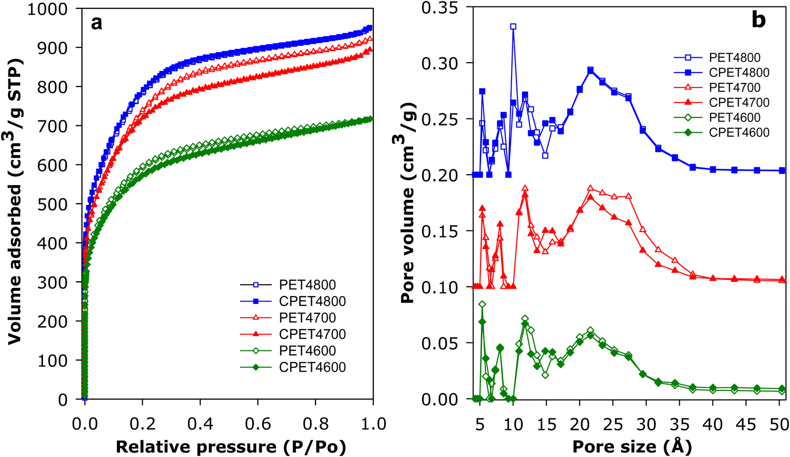 | ||
| Fig. 3 Porosity of PET-derived activated carbon composites. (a) Nitrogen sorption isotherms and (b), pore size distribution (PSD) curves of PET-derived activated carbon composites before and after compaction at 370 MPa for 10 min. The PSD curves of PET4700 and CPET4700 are offset (y-axis) by 0.1, while those of PET4800 and CPET4800 are offset by 0.2. | ||
The textural properties of the PET-derived carbon composites are summarized in Table 2. In the context of activated carbons, the PET-derived composites have moderate to high surface area depending on the activation temperature. As activation temperature rises, the surface area of powder/compacted composites increases from 2154/2045 m2 g−1 for PET4600/CPET4600 to 2650/2590 m2 g−1 for PET4700/CPET4700 and to a high of 2828/2793 m2 g−1 for PET4800/CPET4800. The carbon composites retain at least 95% of surface area after compaction while the pore volume follows a similar trend and varies with activation temperature in the range 1.11–1.47 cm3 g−1, with virtually no change after compaction. It is worth noting that surface area of 2800 m2 g−1 is at the higher end in the context of previously reported results for PET-derived purely carbonaceous activated carbons.47–49 The micro-mesoporous nature of the composites is further evidenced by the proportion of surface area and pore volume arising from micropores, i.e., 80% of surface area, and 66–73% of pore volume. There is no change in the proportion of microporosity after compaction. It is interesting to note that, despite containing some alumina, the surface area of the activated carbon composites is comparable to that of equivalent (in terms of activation conditions) purely carbonaceous activated carbons (Tables S1 and S2, ESI†).12,13,41,42,50–55 This means that the presence of alumina does not adversely affect the surface area achieved for the PETxT activated carbon composites. This is an important observation because the gravimetric methane uptake of porous materials is dependent on their surface area.10–15,21,22 We note that the use of lower amounts of KOH during activation, i.e., KOH/PETHC hydrochar ratio of 2, yielded materials with lower porosity (Table S3, ESI†), which were considered unsuitable for exploration for methane storage.
| Sample | Surface area (m2 g−1) | Micropore surface areaa (m2 g−1) | Pore volume (cm3 g−1) | Micropore volumeb (cm3 g−1) | Surface area densityc (m2 cm−3) | Packing densityd (g cm−3) | Volumetric surface aree (m2 cm−3) |
|---|---|---|---|---|---|---|---|
| a The values in the parenthesis refer to: % micropore surface area. b The values in the parenthesis refer to: % micropore volume. c Surface area density is obtained as the ratio of total surface area to total pore volume. d Packing density of the compacted (at 370 MPa for 10 min) composites (in the form of well-formed discs) was obtained from their mass and volume (volume = πr2h, where r is radius of the disc, i.e., 0.65 cm, and h is the height of the disc). e Volumetric surface area determined as surface area × packing density. | |||||||
| PET4600 | 2154 | 1758 (82) | 1.11 | 0.78 (70) | 1941 | ||
| CPET4600 | 2045 | 1618 (79) | 1.11 | 0.73 (66) | 1842 | 1.13 | 2311 |
| PET4700 | 2650 | 2129 (80) | 1.43 | 0.96 (67) | 1853 | ||
| CPET700 | 2590 | 2079 (80) | 1.38 | 0.93 (67) | 1877 | 1.01 | 2616 |
| PET4800 | 2828 | 2352 (83) | 1.47 | 1.07 (73) | 1924 | ||
| CPET4800 | 2793 | 2292 (82) | 1.47 | 1.06 (72) | 1900 | 0.98 | 2737 |
The packing density of activated carbons may be estimated using the general equation; dcarbon = (1/ρs + VT)−1, where dcarbon is packing density, ρs is skeletal density (2.1 g cm−3) and VT is total pore volume. Thus, if the as-prepared powder forms of the present samples were purely carbonaceous, their estimated packing density (g cm−3) would be 0.63 (PET460), 0.52 (PET4700) and 0.51 (PET4800). However, the fact that the present activated carbon composites contain some alumina (Al2O3), which has a theoretical density of 3.95 g cm−3, means that the composites have a higher packing density than if they were fully carbonaceous. In this regard, we estimated the impact of the alumina on the packing density of the composites by calculating the extent to which the presence of known amounts of alumina would increase the density of a purely carbonaceous activated carbon (Table S4, ESI†). In this way, based on the amount of alumina (from TGA analysis) present in the carbon composites, the estimated packing density of powder forms of the composites is in the range 0.78 to 0.95 g cm−3, i.e., 0.95 g cm−3 for PET4600, 0.79 g cm−3 for PET4700 and 0.78 g cm−3 for PET4800 (Table S4, ESI†). The experimentally determined packing density (based on the mass and volume of the compacted CPET4T composites in the form of discs) of the activated carbon composites is given in Table 2. The packing density of the compacted carbon composites is, as expected, higher than the estimated values stated above for powder forms of the composites (i.e., prior to compaction) due to loss of interparticle voids and some densification. The difference in the packing density estimated for powder forms of the carbon composites (i.e., 0.78 to 0.95 g cm−3) and the experimentally measured values of 0.98 to 1.13 g cm−3 (Table 2) was due to densification arising from compaction. This means that there is a rise in packing density of 19% (CPET4600), 28% (CPET4700) and 26% (CPET4800) once the composites are compacted at 370 MPa (3773 kg cm−2).
The increase in packing density observed on compaction of the present activated carbon composites is consistent with previous reports on the compaction or densification of purely carbonaceous activated carbons. Increases in packing density above 20% have been observed when activated carbons are compacted at pressure of 399 MPa or 887 MPa,56 or even at lower compaction pressure of 55 MPa.57 Furthermore, the packing density of high surface area activated carbons (LMA726 and LMA738) has been reported to rise by more than 40% after compaction at 74 MPa.16 The enhanced packing density of the present compacted carbon composites is due to a combination of the presence of alumina and densification, rather than simply the former. Given the enhanced packing density, the activated carbon composites have the unusual and hitherto unachievable combination of simultaneously having relatively high porosity and high packing density. Indeed, achieving such a balance between porosity and packing density is likely to be out of the reach for purely carbonaceous porous carbons. The presence of small amounts of inorganic matter (alumina) clearly has a significant effect on the packing density of the present activated carbon composites.
The surface area density (i.e., the ratio of total surface area to total pore volume) of the activated carbon composites is given in Table 2. The surface area density (SAD), before and after compaction, is in the relatively narrow range of 1840–1940 m2 cm−3. It is noteworthy that the magnitude of the SAD is consistent with the relatively low O/C ratio (Table 1) of the PET hydrochar.12,13,58 A more interesting parameter with respect to performance of porous materials in gas storage is the volumetric surface area, which has been suggested as a reliable indicator of the volumetric methane storage capacity of any porous solid.12,13,23,24 The volumetric surface area of the carbon composites is in the range of 2310 to 2740 m2 cm−3, and increases with activation temperature. Such volumetric surface area is the highest ever reported for any porous material including activated carbons, MOFs and zeolites. Indeed, there are hardly any reports of porous materials with volumetric surface area above 2000 m2 cm−3 especially for values obtained using experimentally determined packing density rather than crystallographic density. The use of crystallographic density for MOFs can generate overestimated volumetric surface areas.21 The genesis of the exceptional volumetric surface area of the present carbon composites is the enhanced packing density arising from the presence of alumina. The presence of alumina in the activated carbon composites, therefore, enables the preparation of porous materials with a combination of properties (i.e., optimization of both porosity and packing density) that is not achievable via any known synthesis routes or for any class of existing materials.
In order to demonstrate the general applicability of the present approach for the synthesis of carbon composites, we also prepared samples using a different starting material (sawdust) along with addition of a known amount of alumina during the activation step. This was done to demonstrate that any suitable carbon source (precursor) or alumina source (i.e., added alumina or leaching of the alumina boats) can be used to prepare activated carbon composites. The activated carbon product from sawdust hydrochar (SDH) was designated as SDHAC when no alumina was added. With added alumina, the products were designated as SDHACCx, where x is the SDH hydrochar/alumina ratio in the activation mixture. The XRD pattern of SDHAC is typical of amorphous carbon, and no sharp peaks were observed (Fig. S11, ESI†), which confirms that there was no leaching of alumina from the ceramic boat. On the other hand, the SDHACCx samples, which were prepared with added alumina, have patterns typical of amorphous carbon, but crucially also exhibit sharp peaks that are due to the presence of alumina (Fig. S11, ESI†). The pattern of the sharp peaks is similar to that of PET4T samples (Fig. S1 and S2, ESI†). This indicates that the SDHACCx samples are activated carbon composites that are a mixture of activated carbon and alumina in a manner similar to that observed for PET4T carbon composites. TGA curves (Fig. S12, ESI†) show that whilst the SDHAC carbon is completely burnt off with no residual mass (i.e., it is fully carbonaceous), the SDHACCx samples, on the other hand, leave some residual mass that can be attributed to alumina. Furthermore, the residual mass increases with the amount of alumina added (Fig. S12, ESI†). Moreover, the yield and elemental composition provide further evidence of the presence of alumina in the SDHACCx samples. The yield of SDHACCx samples is higher than that of SDHAC (Table S5, ESI†), which we attribute to the presence of retained alumina. Furthermore, the O content of the SDHACCx samples (11 –17.4 wt%) is higher than that of SDHAC (7.8 wt%). The greater O content of the former is due to O associated with the presence of alumina (Table S5, ESI†).
The SDHACCx activated carbon composites have lower porosity compared to the SDHAC carbon (Fig. S13 and Table S6, ESI†). The surface area and pore volume of the SDHAACx composites reduces compared so SDHAC, and the reduction appears to be related to the amount of alumina in the composites; higher alumina content (sample SDHACC8) leads to greater reduction of porosity. However, the porosity still remains relatively high and is comparable to that of the PET4T and CPET4T composites. It is also clear that the presence of alumina shifts the porosity towards micropores; the PSD curves (Fig. S13b, ESI†) show a decrease in the proportion of mesopores while the micropores remains unaffected. This results in an overall increase in the proportion of micropore surface area (from 31% for SDHAC to up to 75% for the SDHACCx carbon composites) and micropore volume (from 24% for SDHAC to up to 69% for the SDHACCx carbon composites). Such levels of microporosity are similar to those of the PET4T and CPET4T carbon composites. What is clear is that the SDHACCx and PET4T activated carbon composites, despite containing some alumina, retain open and accessible porosity that can facilitate methane storage. The alumina, which is retained during the washing step due to insolubility in HCl, is well mixed with the carbon component. This means that the final carbon composite materials are a uniform mix of carbon and alumina as shown by elemental mapping (Fig. S5–S9, ESI†). The sharp peaks in the XRD patterns of both PETxT and SDHACCx composites (Fig. 1 and Fig. S1, S2 and S11, ESI†) also confirm that there are distinct particles of alumina uniformly interspersed within the carbon matrix.
3.3 Methane storage
The methane uptake of the activated carbon composites was measured at 25 °C and pressure of up to 100 bar. The measurements determined the excess uptake from which the total methane storage capacity was obtained by taking onto account the density of methane under the uptake conditions (i.e., 25 °C and uptake pressure) and the total pore volume of the adsorbing carbon composite. The equation θT = θExc + (dCH4 × VT), was used, where; θT is total methane uptake, θExc is the excess methane uptake, dCH4 is the density (g cm−3) of methane gas at 25 °C and the uptake pressure (https://www.nist.gov/), and VT is total pore volume (cm3 g−1) of the carbon composite. The excess and total gravimetric methane uptake isotherms of the carbon composites are shown in Fig. 4, and Table 3 gives the storage capacity at a range of pressures (35, 65, 80 and 100 bar). The excess methane uptake isotherms are fully reversible (Fig. S14, ESI†) and they are also repeatable (Fig. S15, ESI†), which vouches for the veracity of our measurements. Measurement of methane uptake using empty sample holders indicated nil uptake (Fig. S16, ESI†). The excess uptake appears to approach saturation at 90 bar with limited increase at pressures above 80 bar. The excess uptake is in line with the surface area of the composites, which is consistent with previous observations on the link between gravimetric methane uptake and the surface area for porous materials.10–15,21,22 Methane storage at 35 bar has been suggested as being compatible with vehicular use in an internal combustion engine.21 The excess uptake at 35 bar is 8.5–10.8 mmol g−1, and is comparable to that of the best carbon or MOF materials reported to date.12,13,16–18,59–61 The excess uptake increases to between 10.3 and 12.7 mmol g−1 at 65 bar, and reaches a high of 13.4 mmol g−1 for sample CPET4800 at 100 bar.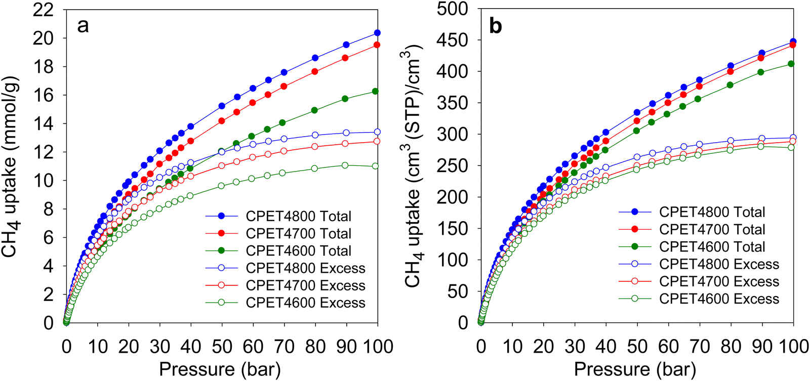 | ||
| Fig. 4 Methane uptake of PET-derived activated carbon composites. (a) Gravimetric methane uptake as a function of uptake pressure. (b) Volumetric methane uptake as a function of uptake pressure. | ||
| Sample | Gravimetric methane uptake (mmol g−1) | |||||||
|---|---|---|---|---|---|---|---|---|
| Excess uptake | Total uptake | |||||||
| 35 bar | 65 bar | 80 bar | 100 bar | 35 bar | 65 bar | 80 bar | 100 bar | |
| CPET4600 | 8.5 | 10.3 | 10.8 | 11.0 | 10.2 | 13.6 | 14.9 | 16.2 |
| CPET4700 | 9.8 | 11.8 | 12.4 | 12.7 | 11.9 | 16.0 | 17.6 | 19.5 |
| CPET4800 | 10.8 | 12.7 | 13.2 | 13.4 | 13.0 | 17.0 | 18.6 | 20.4 |
The excess uptake gives an indication of the extent to which methane molecules interact with the adsorbing surface. It is therefore necessary to ascertain whether the presence of alumina alters the surface functionality and consequently the nature of methane adsorption of the activated carbon composites compared to fully carbonaceous activated carbons. The interaction between an adsorbing surface and methane molecules (i.e., the inherent adsorbing ability) can be probed by considering the amount of excess methane stored per unit surface area (Fig. S17, ESI†), which equates to gravimetric uptake density. The trends and amounts observed for the PET-derived activated carbon composites are comparable to those of a suite of previously reported fully carbonaceous carbons (Fig. S17, ESI†). This is also the case for the sawdust-derived SDHACCx activated carbon composites (Fig. S18, ESI†). The alumina free SDHAC activated carbon and SDHACC8 activated carbon composite have gravimetric methane uptake that is in line with their surface area (Fig. S18, ESI†). The activated carbon composites, regardless of the starting material (i.e., PET or sawdust) have comparable gravimetric methane uptake density, which is also similar to that of fully carbonaceous activated carbons (Fig. S17 and S18, ESI†). This confirms that for methane adsorption, the surface of the activated carbon composites is inherently similar in nature to that of purely carbonaceous activated carbons.
To further confirm this finding, we also determined the isosteric heat of adsorption (Qst) to ascertain whether it is within the range expected for methane storage in porous carbons. To determine Qst, the experimentally determined isotherms (excess uptake) were fit, using the Whittaker method, to a Toth model.62–64 In order to use the Whittaker method in this way, a specific python module was created in pyGAPS.62–64 The Qst of the carbon composites (Fig. S19, ESI†) was found to be in the range of 19–13 kJ mol−1 for methane loading of up to 6 mmol g−1. The Qst of the carbon composites is therefore in line with that of activated carbons and other porous carbons, which generally is in the range of 10 to 25 kJ mol−1.65 This confirms that from a thermodynamics viewpoint, the nature of the interaction between methane molecules and the surface of the carbon composites is similar to that of methane adsorbing on purely carbonaceous carbons. Apart from Qst, the kinetics of sorption and diffusivity can also affect the uptake of methane. It has been shown that activated carbon AX21, which has porosity similar to the present carbon composites, has an average methane mass transfer coefficient (MTC) of 12.8 min−1 at 27 °C and effective diffusivity (Deff) of 1.79 × 10⁻¹³ m2 s−1.66 Such MTC and Deff values are similar to those that have been observed for a wide range of porous materials including activated carbons, MOFs and zeolites.66 The methane diffusion coefficients at ambient temperature are of the order of magnitude that is favourable for both methane storage (at high pressure) and methane release at lower pressures.66,67 It is noteworthy that the pores of the carbon composites (>5 Å and up to 35 Å) is much larger than methane (3.8 Å).
For gravimetric uptake, the total amount stored is the key performance indicator. The total gravimetric methane uptake is given in Table 3, and is in the range of 10.2 to 13.0 mmol g−1 at 35 bar, 13.6 to17.0 mmol g−1 at 65 bar, and reaches a high of 16.2–20.4 mmol g−1 at 100 bar. These values translate to g g−1 uptake of 0.16–0.21 at 35 bar, 0.22–0.27 at 65 bar, 0.24–0.30 at 80 bar, and 0.26–0.33 at 100 bar (Table S7, ESI†). The gravimetric uptake of the present carbon composites compares well with that of previously reported benchmark carbon and MOF materials.10–17,21
Regarding methane storage applications, the volumetric uptake is a better indicator of performance than the gravimetric uptake. Apart from the gravimetric methane uptake, the packing density of an adsorbent is the other key factor in determining the suitability of a porous material for use as an adsorbent in a gas storage tank with defined volume. The high packing density of the present carbon composites means that more of them can be contained within a storage tank with minimal interparticle space thus maximizing the use of tank volume. The key volumetric methane storage target in porous materials has been set by the US Department of Energy (DOE) at 263 cm3 (STP) cm−3 at 25 °C and moderate pressure (35–100 bar). The volumetric methane storage isotherms of the carbon composites are shown in Fig. 4(b), and the uptake at various pressures is given in Table 4. The total volumetric uptake isotherms do not approach saturation even at 100 bar, which means that the carbon composites can reach even higher levels of storage at pressures greater than 100 bar. At 35 bar, the lowest pressure claimed to be relevant to vehicular use, the carbon composites have high total volumetric storage capacity (cm3 (STP) cm−3) of 257, 270 and 285, respectively for CPET4600, CPET4700 and CPET4800. To date, no carbon has been reported with such high volumetric uptake at 35 bar; the best uptake to date are 222 cm3 (STP) cm−3 for an activated carbon (ACDS4700) derived from air-carbonised date seed, and 235 cm3 (STP) cm−3 for an activated carbon (CHCC2800) derived from cloves.12,13,59 Likewise, there are no reports to date of MOFs with such high volumetric uptake at 35 bar even when values are computed using crystallographic density.11,14,15,21–24 It is remarkable to note that the volumetric uptake of CPET4800 at 35 bar (285 cm3 (STP) cm−3) is higher than the best values reported for powder forms of MOFs at 100 bar.21 This is despite the fact that the volumetric uptake of such benchmark MOFs is calculated using crystallographic density, which is known to yield overestimated values.21,22 The only MOF with volumetric storage performance that comes close to that of the present carbon composites is the monolithic monoHKUST-1, which at 35 bar and 25 °C has uptake of 224 cm3 (STP) cm−3. The monoHKUST-1 sample has been reported to have a high packing density of 1.06 g cm−3 and is currently considered to be the record holder in terms of volumetric methane storage in MOFs.23,24 The performance of the present activated carbon composites is the first time that any porous material has achieved methane volumetric uptake that surpasses the DOE target of 263 cm3 (STP) cm−3 at a relatively low pressure of 35 bar.
| Sample | Volumetric methane uptake (cm3 (STP) cm−3) | |||||||
|---|---|---|---|---|---|---|---|---|
| Excess uptake | Total uptake | |||||||
| 35 bar | 65 bar | 80 bar | 100 bar | 35 bar | 65 bar | 80 bar | 100 bar | |
| CPET4600 | 215 | 261 | 274 | 278 | 257 | 344 378 | 378 | 412 |
| CPET4700 | 221 | 268 | 280 | 288 | 270 | 362 399 | 399 | 442 |
| CPET4800 | 236 | 280 | 289 | 294 | 285 | 374 408 | 408 | 447 |
At 65 bar, the total volumetric methane uptake rises to 344 cm3 (STP) cm−3 (CPET4600), 362 cm3 (STP) cm−3 (CPET4700), and 374 cm3 (STP) cm−3 for CPET4800. It is remarkable that at 65 bar, the present carbon composites have volumetric storage capacity (up to 374 cm3 (STP) cm−3) that MOFs can only attain at much higher pressure of 250 bar.68 As shown in Table 4, the volumetric uptake increases further at 100 bar to 412 cm3 (STP) cm−3 for CPET4600, 442 cm3 (STP) cm−3 for CPET4700, and 447 cm3 (STP) cm−3 for CPET4800. Compared to the performance of current benchmark porous materials, the volumetric uptake of the present carbon composites offers a step change in the amount of methane that can be stored.11–15,21–24 For a proper context of the performance of the carbon composites, Fig. 5(a) shows a comparison with a range of current leading benchmark MOFs, including NU-1501-Al, HKUST-1, MOF-5, Ni-MOF-74 and PCN-14.11,21,22,69–72 The carbon composites are also compared (Table S8, ESI†) to a range of top performing porous materials (including Al-soc-MOF-1, MOF-210, NU-1500-Al, NU-1501-Fe and NU-1501-Al), in respect of their uptake (total volumetric and gravimetric, as g g−1) at 65, 80 and 100 bar. It is clear from Fig. 5(a) that the uptake of the carbon composites exceeds that of current benchmark carbons and MOFs. The volumetric uptake of the carbon composites is higher than that of one of the best MOFs (HKUST-1) by 40%, 50% and 60%, respectively at 65, 80 and 100 bar. To remove any ambiguity arising from the use of crystallographic density, we also compared the carbon composites with monolithic forms of MOFs, namely monoHKUST-1 and monoUiO-66_D.23,24 The carbon composites are superior as shown in Fig. 5(b) (and Table S8, ESI†). Apart from permanently porous materials, Rozyyev and co-workers have reported on a flexible porous polymer, COP-150, which can store up to 301 cm3 (STP) cm−3 at 100 bar but at the lower temperature of 0 °C.73 At 25 °C, the volumetric (and gravimetric) uptake of COP-150 is much lower, which combined with a relatively low packing density (0.34 g cm−3) mean that it best operates at lower temperature. Nevertheless, the present carbon composites have higher volumetric methane uptake at 25 °C than the uptake of COP-150 at 0 °C.
 | ||
| Fig. 5 Volumetric methane uptake of PET-derived activated carbon composites compared with that of (a) benchmark MOF materials, and (b) monolithic MOFs. The data for the powder MOFs in (a) is from ref. 11 and 21, while that for monoHKUST-1 and monoUiO-66_D it is from ref. 23 and 24, respectively. | ||
The most important parameter in evaluating the performance of porous materials as stores for methane is the amount (expressed in volumetric terms) that can be delivered as ‘working capacity’ or ‘deliverable capacity’. The working capacity is the difference in storage between two pressures; a higher uptake pressure, which for methane should typically be at least 35 bar, and a lower delivery pressure. Here, we determined the working capacity as the difference between storage at the uptake pressure (35 bar or above) and 5 bar as the delivery pressure. Fig. 6(a) shows the trend in working capacity as a function of the uptake pressure in the range 5–100 bar. The working capacity (cm3 (STP) cm−3) for a 35 to 5 bar pressure swing is 177 for CPET4600, 186 for CPET4700 and 191 for CPET4800. This is higher than the best carbons and MOFs reported to date, which reach 130 (ACDS4700)12 142 (CHCC4700)59 or 140 (monoHKUST-1).23 A pressure swing of 35 to 1 bar has recently been suggested as also being suitable for methane delivery, in which case the working capacity increases to 233 (CPET4600), 246 (CPET4700) and 256 (CPET4800). For a 65 to 5 bar pressure swing, the working capacity rises to 264 (CPET4600), 278 (CPET4700) and 280 (CPET4800). These working capacity values are very impressive especially in the context of the US DOE recently setting a target of 315 cm3 (STP) cm−3 for pressure swings of 35 to 1 bar or 65 to 5.8 bar. The target of 315 cm3 (STP) cm−3 is set for single crystal materials with the expectation of a 25% reduction due to packing loss. In essence the real target is therefore 236 cm3 (STP) cm−3 for pressure swings of 35 to 1 bar or 65 to 5 bar. The present compacted carbon composites, which are not subject to packing loss, therefore, achieve and exceed the DOE target for methane delivery for both the 35 to 1 bar and 65 to 5.8 bar swings. For an 80 to 5 bar pressure swing, the working capacity rises to 298 (CPET4600), 315 (CPET4700) and 314 (CPET4800). The highest deliverable methane for 100 to 5 bar pressure swing is 332 for sample CPET4600, 358 for CPET4700 and 353 for CPET4800. These values are far higher than for the best MOFs as shown in Fig. 6(b) (and Table S9, ESI†).11–15,68–72 The carbon composites also outperform monolithic MOFs for which volumetric uptake (for 100 to 1 bar pressure swing) has been determined using experimentally obtained packing density, i.e. (198 cm3 (STP) cm−3) and (253 cm3 (STP) cm−3) for monoHKUST-1 and monoUiO-66_D, respectively. The flexible polymer, COP-150, has been reported to achieve working capacity of 294 cm3 (STP) cm−3 but at the lower temperature of 0 °C.73 For ANG technology, it is preferable that storage and release operations are carried out at ambient temperature, or that usable materials show good performance at 25 °C, which may improve at lower temperature.
 | ||
| Fig. 6 Deliverable methane (working capacity) of PET-derived activated carbon composites. (a) Working capacity as a function of uptake pressure. (b) Working capacity of carbon composites compared with that of benchmark MOF materials. The data for the powder MOFs (NU-1501-Al, HKUST-1 and Ni-MOF-74) is from ref. 11 and data for monoHKUST-1 and monoUiO-66_D is from ref. 23 and 24, respectively. | ||
An important consideration is the scalability of the synthesis of the activated carbon composites. The synthesis route involves two steps that are well established and are already extensively used in the preparation of carbons; namely hydrothermal carbonisation and KOH activation. The PET waste bottles (or any other starting material, including biomass) are converted to hydrochar via hydrothermal carbonisation, which is an environmentally benign process. Activation of hydrochars is an established process, which is not dependent on the source of the hydrochar. As we have shown, addition of alumina (or other suitable inorganic additives) does not affect the activation process. Overall, this means that scalability of synthesis of the activated carbon composites is readily achievable. Moreover, since it is based on established processes, the synthesis does not present any new economic or environmental challenges beyond those already know for the preparation of activated carbons. The expectation is that the energy demand and extent of CO2 emissions associated with preparation of the activated carbon composites will be similar to that of activated carbons. The use of biomass as starting material would be advantageous in terms of the CO2 balance. The use of recyclable waste such as PET bottles as starting materials would benefit from the fact that there already exist processes for collecting, cleaning and sorting such waste into a form suitable for conversion to hydrochar via hydrothermal carbonisation.
4. Conclusions
We have presented a new concept and approach to porous carbon-based materials that simultaneously exhibit both high porosity and high packing density. The approach follows well established processes for the synthesis of activated carbons via KOH activation but with a twist in the procedures that allows inclusion of some inorganic matter as a minor component in the final carbon composites. The activated carbon composites exhibit high surface area (up to 2800 m2 g−1), pore volume (up to 1.5 cm3 g−1), and have high packing density (ca. 1.0 g cm−3). The inorganic component, which in the present case is mainly alumina, contributes to the rise in packing density. The high porosity translates to attractive gravimetric methane storage in a manner similar to that of equivalent (in terms of porosity) activated carbons or MOFs. However, due to their enhanced packing density, the activated carbon composites have extraordinary levels of volumetric methane uptake that exceed all previously been reported values for any class of porous materials. At 25 °C, the methane uptake of the activated carbon composites reaches 285 cm3 (STP) cm−3 at 35 bar, 374 cm3 (STP) cm−3 at 65 bar and 447 cm3 (STP) cm−3 at 100 bar. These methane storage values meet set volumetric uptake targets (e.g., DOE target of 263 cm3 (STP) cm−3) even at the relatively low pressure of 35 bar. The activated carbon composites are the first porous materials to meet the DOE target at 35 bar. The exceptional volumetric storage capacity is accompanied by record levels of deliverable methane (working capacity) of up to 256 cm3 (STP) cm−3 for a pressure swing of 35 to 1 bar, 280 cm3 (STP) cm−3 for a 65 to 5 bar pressure swing, and 358 cm3 (STP) cm−3 for a 100 to 5 bar pressure swing. These methane storage and delivery values represent a step change in the level of attainable volumetric storage of methane, and by extension natural gas (NG), as a fuel especially for vehicular use. The properties (balance of porosity and packing density) and methane uptake performance of the activated carbon composites address the main barrier to the use of NG as a fuel for vehicles and other forms of transportation, i.e., the lack of materials that can store sufficient amounts of NG under accessible operating conditions. Indeed, the porosity-packing density balance of the activated carbon composites seems, at the present time, to be unreachable for purely carbonaceous porous carbons or MOFs. Although in this report we have used waste plastic (polyethylene terephthalate, PET) and sawdust as starting materials (precursors) and KOH as activating agent, a wide range of other precursors and activators can be used. Furthermore, our concept and findings offer new insights that are of wider relevance and application to the development of porous materials for energy related gas (CH4, H2, CO2, etc) storage.Author contributions
R. M. conceived the idea and methodology, and wrote the final version of the manuscript. I. A. performed the materials synthesis and characterization under the supervision of R. M., and wrote the first draft of the manuscript. A. U. S. performed some materials synthesis and characterization under the supervision of R. M.Data availability statement
The data presented in this study are available and may be obtained by contacting the corresponding author.Conflicts of interest
There are no conflicts of interest to declare.Acknowledgements
We are grateful to the Nanoscale and Microscale Research Centre (nmRC) at the University of Nottingham for assistance with Raman and microscopy analysis. We thank Leo Scott Blankenship for assistance with determination of Qst values. We thank Jouf University, Kingdom of Saudi Arabia, for funding a PhD studentship for Ibtisam Alali, and the Petroleum Technology Development Fund (PTDF), Nigeria, for funding a PhD studentship for Amina Shehu. RM thanks the Royal Society for a Research Grant, and for a Royal Society Wolfson Research Merit Award.References
- M. Bui, C. S. Adjiman, A. Bardow, E. J. Anthony, A. Boston, S. Brown, P. S. Fennell, S. Fuss, A. Galindo, L. A. Hackett, J. P. Hallett, H. J. Herzog, G. Jackson, J. Kemper, S. Krevor, G. C. Maitland, M. Matuszewski, I. S. Metcalfe, C. Petit, G. Puxty, J. Reimer, D. M. Reiner, E. S. Rubin, S. A. Scott, N. Shah, B. Smit, J. P. M. Trusler, P. Webley, J. Wilcox and N. Mac Dowell, Carbon capture and storage (CCS): the way forward, Energy Environ. Sci., 2018, 11, 1062–1176 RSC.
- S. J. Davis, K. Caldeira and H. D. Matthews, Future CO2 emissions and climate change from existing energy infrastructure, Science, 2010, 329, 1330–1333 CrossRef CAS PubMed.
- K. S. Lackner, S. Brennan, J. M. Matter, A.-H. A. Park, A. Wright and B. van der Zwaan, The urgency of the development of CO2 capture from ambient air, Proc. Natl. Acad. Sci. U. S. A., 2010, 109, 13156–13162 CrossRef PubMed.
- D. Y. C. Leung, G. Caramanna and M. M. Maroto-valer, An overview of current status of carbon dioxide capture and storage technologies, Renewable Sustainable Energy Rev., 2014, 39, 426–443 CrossRef CAS.
- P. Poizot and F. Dolhem, Clean energy new deal for a sustainable world: from non-CO2 generating energy sources to greener electrochemical storage devices, Energy Environ. Sci., 2011, 4, 2003–2019 RSC.
- L. C. Yang, X. M. Ge, C. X. Wan, F. Yu and Y. B. Li, Progress and perspectives in converting biogas to transportation fuels, Renewable Sustainable Energy Rev., 2014, 40, 1133–1152 CrossRef CAS.
- K. V. Kumar, K. Preuss, M. M. Titirici and F. Rodriguez-Reinoso, F. Nanoporous materials for the onboard storage of natural gas, Chem. Rev., 2017, 117, 1796–1825 CrossRef CAS PubMed.
- I. Angelidaki, L. Treu, P. Tsapekos, G. Luo, S. Campanaro, H. Wenzel and P. Kougias, Biogas upgrading and utilization: Current status and perspectives, Biotechnol. Adv., 2018, 36, 452466 CrossRef PubMed.
- I. U. Khan, M. H. D. Othman, H. Hashim, T. Matsuura, A. F. Ismail, M. Rezaei-DashtArzhandi and I. W. Azelee, Biogas as a renewable energy fuel – A review of biogas upgrading, utilisation and storage, Energy Convers. Manage., 2017, 150, 277–294 CrossRef.
- T. A. Makal, J. R. Li, W. Lu and H. C. Zhou, Methane storage in advanced porous materials, Chem. Soc. Rev., 2012, 41, 7761–7779 RSC.
- J. A. Mason, M. Veenstra and J. R. Long, Evaluating metal–organic frameworks for natural gas storage, Chem. Sci., 2014, 5, 32–51 RSC.
- A. Altwala and R. Mokaya, Predictable and targeted activation of biomass to carbons with high surface area density and enhanced methane storage capacity, Energy Environ. Sci., 2020, 13, 2967–2978 RSC.
- A. Altwala and R. Mokaya, Modulating the porosity of activated carbons via pre-mixed precursors for simultaneously enhanced gravimetric and volumetric methane uptake, J. Mater. Chem. A, 2022, 10, 13744–13757 RSC.
- B. Li, H.-M. Wen, W. Zhou, J. Q. Xu and B. Chen, Porous metal-organic frameworks: Promising materials for methane storage, Chem, 2016, 1, 557–580 CAS.
- Y. He, W. Zhou, G. Qian and B. Chen, Methane storage in metal–organic frameworks, Chem. Soc. Rev., 2014, 43, 5657–5678 RSC.
- M. E. Casco, M. Martínez-Escandell, E. Gadea-Ramos, K. Kaneko, J. Silvestre-Albero and F. Rodríguez-Reinoso, High-Pressure methane storage in porous materials: Are carbon materials in the pole position?, Chem. Mater., 2015, 27, 959–964 CrossRef CAS.
- S. Choi, M. A. Alkhabbaz, Y. Wang, R. M. Othman and M. Choi, Unique thermal contraction of zeolite-templated carbons enabling micropore size tailoring and its effects on methane storage, Carbon, 2019, 141, 143–153 CrossRef CAS.
- M. E. Casco, M. Martinez-Escandell, K. Kaneko, J. Silvestre-Albero and F. Rodriguez-Reinoso, Very high methane uptake on activated carbons prepared from mesophase pitch: A compromise between microporosity and bulk density, Carbon, 2015, 93, 11–21 CrossRef CAS.
- A. Memetova, I. Tyagi, R. R. Karri, V. Kumar, K. Tyagi, S. N. Memetov, A. Zelenin, T. Pasko, A. Gerasimova, D. Tarov, M. H. Dehghani and K. Singh, Porous carbon-based material as a sustainable alternative for the storage of natural gas (methane) and biogas (biomethane): A review, Chem. Eng. J., 2022, 446, 137373 CrossRef CAS.
- L. S. Blankenship and R. Mokaya, Modulating the porosity of carbons for improved adsorption of hydrogen, carbon dioxide, and methane: a review, Mater. Adv., 2022, 3, 1905–1930 RSC.
- Z. Chen, P. Li, R. Anderson, X. Wang, X. Zhang, L. Robison, L. R. Redfern, S. Moribe, T. Islamoglu, D. A. Gomez-Gualdron, T. Yildirim, J. F. Stoddart and O. K. Farha, Balancing volumetric and gravimetric uptake in highly porous materials for clean energy, Science, 2020, 368, 297–303 CrossRef CAS PubMed.
- Y. Peng, V. Krungleviciute, I. Eryazici, J. T. Hupp, O. K. Farha and T. Yildirim, Methane storage in Metal–Organic Frameworks: Current records, surprise findings, and challenges, J. Am. Chem. Soc., 2013, 135, 11887–11894 CrossRef CAS PubMed.
- T. Tian, Z. Zeng, D. Vulpe, M. E. Casco, G. Divitini, P. A. Midgley, J. Silvestre-Albero, J. C. Tan, P. Z. Moghadam and D. Fairen-Jimenez, A sol–gel monolithic metal-organic framework with enhanced methane uptake, Nat. Mater., 2018, 17, 174–179 CrossRef CAS PubMed.
- B. M. Connolly, M. Aragones-Anglada, J. Gandara-Loe, N. A. Danaf, D. C. Lamb, J. P. Mehta, D. Vulpe, S. Wuttke, J. Silvestre-Albero, P. Z. Moghadam, A. E. H. Wheatley and D. Fairen-Jimenez, Tuning porosity in macroscopic monolithic metal-organic frameworks for exceptional natural gas storage, Nat. Commun., 2019, 10, 2345 CrossRef CAS PubMed.
- K. W. Chapman, G. J. Halder and P. J. Chupas, Pressure-induced amorphization and porosity modification in a Metal−Organic Framework, J. Am. Chem. Soc., 2009, 131, 17546–17547 CrossRef CAS PubMed.
- J. P. Marco-Lozar, J. Juan-Juan, F. Suarez-Garcıa, D. Cazorla-Amoros and A. Linares-Solano, MOF-5 and activated carbons as adsorbents for gas storage, Int. J. Hydrogen Energy, 2012, 37, 2370–2381 CrossRef CAS.
- P. X. Hou, H. Orikasa, H. Itoi, H. Nishihara and T. Kyotani, Densification of ordered microporous carbons and controlling their micropore size by hot-pressing, Carbon, 2007, 45, 2011–2016 CrossRef CAS.
- E. Masika and R. Mokaya, Exceptional gravimetric and volumetric hydrogen storage for densified zeolite templated carbons with high mechanical stability, Energy Environ. Sci., 2014, 7, 427–434 RSC.
- C. Guan, L. S. Loo, K. Wang and C. Yang, Methane storage in carbon pellets prepared via a binderless method, Energy Convers. Manage., 2011, 52, 1258–1262 CrossRef CAS.
- A. Celzard, A. Albiniak, M. Jasienko-Halat, J. F. Mareche and G. Furdin, Methane storage capacities and pore textures of active carbons undergoing mechanical densification, Carbon, 2005, 43, 1990–1999 CrossRef CAS.
- A. Memetova, I. Tyagi, R. R. Karri, S. N. Memetov, A. Zelenin, R. Stolyarov, A. Babkin, V. Yagubov, I. Burmistrov, A. Tkachev, V. Bogoslovskiy, G. Shigabaeva and E. Galunin, High-Density Nanoporous carbon materials as storage material for Methane: A value-added solution, Chem. Eng. J., 2022, 433, 134608 CrossRef CAS.
- J. P. Singer, A. Mayergoyz, C. Portet, E. Schneider, Y. Gogotsi and J. E. Fischer, Enhanced volumetric hydrogen storage capacity of porous carbon powders by forming peels or pellets, Microporous Mesoporous Mater., 2008, 116, 469–472 CrossRef CAS.
- J. P. Marco-Lozar, M. Kunowsky, F. Suárez-García, J. D. Carruthers and A. Linares-Solano, Activated carbon monoliths for gas storage at room temperature, Energy Environ. Sci., 2012, 5, 9833–9842 RSC.
- H. Sardon and A. P. Dove, Plastics recycling with a difference, Science, 2018, 360, 380–381 CrossRef CAS PubMed.
- J. N. Hahladakis, C. A. Velis, R. Weber, E. Iacovidou and P. Purnell, An overview of chemical additives present in plastics: Migration, release, fate and environmental impact during their use, disposal and recycling, J. Hazardous Mater., 2018, 344, 179–199 CrossRef CAS PubMed.
- A. Stubbins, L. L. Law, S. E. Munoz, T. S. Bianchi and L. X. Zhu, Plastics in the Earth system, Science, 2021, 373, 51–55 CrossRef CAS PubMed.
- K. Ragaert, L. Delva and K. Van Geem, Mechanical and chemical recycling of solid plastic waste, Waste Manage., 2017, 69, 24–58 CrossRef CAS PubMed.
- I. Vollmer, M. J. F. Jenks, M. C. P. Roelands, R. J. White, T. van Harmelen, P. de Wild, G. P. van der Laan, F. Meirer, J. T. F. Keurentjes and B. M. Weckhuysen, Beyond mechanical recycling: Giving new life to plastic waste, Angew. Chem., Int. Ed., 2020, 59, 215402 CrossRef PubMed.
- S. L. Chen, Z. Liu, S. H. Jiang and H. Q. Hou, Carbonization: A feasible route for reutilization of plastic wastes, Sci. Total Environ., 2020, 710, 136250 CrossRef CAS PubMed.
- M. Sevilla and A. B. Fuertes, The production of carbon materials by hydrothermal carbonization of cellulose, Carbon, 2009, 47, 2281–2289 CrossRef CAS.
- E. A. Hirst, A. Taylor and R. Mokaya, A simple flash carbonization route for conversion of biomass to porous carbons with high CO2 storage capacity, J. Mater. Chem. A, 2018, 6, 12393–12403 RSC.
- W. Sangchoom and R. Mokaya, Valorization of lignin waste: Carbons from hydrothermal carbonization of renewable lignin as superior sorbents for CO2 and hydrogen storage, ACS Sustainable Chem. Eng., 2015, 3, 1658–1667 CrossRef CAS.
- J. Wang and K. Stefan, KOH activation of carbon-based materials for energy storage, J. Mater. Chem., 2012, 22, 23710–23725 RSC.
- W. Chen, M. Gong, K. Li, M. Xia, Z. Chen, H. Xiao, Y. Fang, Y. Chen, H. Yang and H. Chen, Insight into KOH activation mechanism during biomass pyrolysis: Chemical reactions between O-containing groups and KOH, Appl. Energy, 2020, 278, 115730 CrossRef CAS.
- E. Masika and R. Mokaya, Hydrogen storage in high surface area carbons with identical surface areas but different pore sizes: Direct demonstration of the effects of pore size, J. Phys. Chem. C, 2012, 116, 25734–25740 CrossRef CAS.
- X. Liu, Y. Sun, J. Liu, C. Sun, H. Liu, Q. Xue, E. Smith and C. Snape, Potassium and zeolitic structure modified ultra-microporous adsorbent materials from a renewable feedstock with favorable surface chemistry for CO2 capture., ACS Appl. Mater. Interfaces, 2017, 9, 26826–26839 CrossRef CAS PubMed.
- R. Mendoza-Carrasco, E. M. Cuerda-Correa, M. F. Alexandre-Franco, C. Fernández-González and V. Gómez-Serrano, Preparation of high-quality activated carbon from polyethyleneterephthalate (PET) bottle waste. Its use in the removal of pollutants in aqueous solution, J. Environ. Manage., 2016, 181, 522–535 CrossRef CAS PubMed.
- X. Yuan, J. G. Lee, H. Yun, S. Deng, Y. J. Kim, J. E. Lee, S. K. Kwak and K. B. Lee, Solving two environmental issues simultaneously: Waste polyethylene terephthalate plastic bottle-derived microporous carbons for capturing CO2, Chem. Eng. J., 2020, 397, 125350 CrossRef CAS.
- B. Kaur, J. Singh, R. K. Gupta and H. Bhunia, Porous carbons derived from polyethylene terephthalate (PET) waste for CO2 capture studies., J. Environ. Manage., 2019, 242, 68–80 CrossRef CAS PubMed.
- E. Haffner-Staton, N. Balahmar and R. Mokaya, High yield and high packing density porous carbon for unprecedented CO2 capture from the first attempt at activation of air-carbonized biomass, J. Mater. Chem. A, 2016, 4, 13324–13335 RSC.
- N. Balahmar, A. S. Al-Jumialy and R. Mokaya, Biomass to porous carbon in one step: directly activated biomass for high performance CO2 storage, J. Mater. Chem. A, 2017, 5, 12330–12339 RSC.
- M. Sevilla, A. B. Fuertes and R. Mokaya, High density hydrogen storage in superactivated carbons from hydrothermally carbonized renewable organic materials, Energy Environ. Sci., 2011, 3, 1400–1410 RSC.
- H. M. Coromina, D. Walsh and R. Mokaya, Biomass-derived activated carbon with simultaneously enhanced CO2 uptake for both pre and post combustion capture applications, J. Mater. Chem. A, 2016, 4, 280–289 RSC.
- L. S. Blankenship, N. Balahmar and R. Mokaya, Oxygen-rich microporous carbons with exceptional hydrogen storage capacity, Nat. Commun., 2017, 8, 1545 CrossRef PubMed.
- L. S. Blankenship and R. Mokaya, Cigarette butt-derived carbons have ultra-high surface area and unprecedented hydrogen storage capacity, Energy Environ. Sci., 2017, 10, 2552–2562 RSC.
- D. Lia, Y. Wang, X. Zhang, J. Zhou, Y. Yang, Z. Zhang, L. Wei, Y. Tiana and X. Zhao, Effects of compacting activated carbons on their volumetric CO2 adsorption performance, Fuel, 2020, 262, 116540 CrossRef.
- T. Zhang, W. P. Walawender and L. T. Fan, Grain-based activated carbons for natural gas storage, Bioresour. Technol., 2010, 101, 1983–1991 CrossRef CAS PubMed.
- N. Balahmar and R. Mokaya, Pre-mixed precursors for modulating the porosity of carbons for enhanced hydrogen storage: towards predicting the activation behaviour of carbonaceous matter, J. Mater. Chem. A, 2019, 7, 17466–17479 RSC.
- I. Alali and R. Mokaya, Generalised predictability in the synthesis of biocarbons as clean energy materials: targeted high performance CO2 and CH4 storage, Energy Environ. Sci., 2022, 15, 4710–4724 RSC.
- S. Bracco, D. Piga, I. Bassanetti, J. Perego, A. Comotti and P. Sozzani, Porous 3D polymers for high pressure methane storage and carbon dioxide capture, J. Mater. Chem. A, 2017, 5, 10328–10337 RSC.
- I. Alali and R. Mokaya, Direct synthesis of organic salt-derived porous carbons for enhanced CO2 and methane storage, J. Mater. Chem. A, 2023, 11, 6952–6965 RSC.
- P. Iacomi and P. L. Llewellyn, pyGAPS: a Python-based framework for adsorption isotherm processing and material characterisation, Adsorption, 2019, 25, 1533–1542 CrossRef CAS.
- P. B. Whittaker, X. Wang, K. Regenauer-Lieb and H. T. Chua, Predicting isosteric heats for gas adsorption, Phys. Chem. Chem. Phys., 2013, 15, 473–482 RSC.
- N. Albeladi, L. Scott Blankenship and R. Mokaya, Ultra-high surface area ionic-liquid-derived carbons that meet both gravimetric and volumetric methane storage targets, Energy Environ. Sci., 2024, 17, 3060–3076 RSC.
- J. Abdulsalam, J. Mulopo, S. O. Bada and B. Oboirien, Equilibria and isosteric heat of adsorption of methane on activated carbons derived from South African coal discards, ACS Omega, 2020, 5, 32530–32539 CrossRef CAS PubMed.
- N. Bimbo, J. P. Smith, H. Aggarwal, A. J. Physick, A. Pugsley, L. J. Barbour, V. P. Ting and T. J. Mays, Kinetics and enthalpies of methane adsorption in microporous materials AX-21, MIL-101 (Cr) and TE7, Chem. Eng. Res. Des., 2021, 169, 153–164 CrossRef CAS.
- D. Cao, X. Zhang, J. Chen and J. Yun, local diffusion coefficient of supercritical methane in activated carbon by molecular simulation, Carbon, 2003, 41, 2653–2689 CrossRef.
- F. Gandara, H. Furukawa, S. Lee and O. M. Yaghi, High methane storage capacity in Aluminum Metal−Organic Frameworks, J. Am. Chem. Soc., 2014, 136, 5271–5274 CrossRef CAS PubMed.
- S. Ma, D. Sun, J. M. Simmons, C. D. Collier, D. Yuan and H.-C. Zhou, Metal-organic framework from an anthracene derivative containing nanoscopic cages exhibiting high methane uptake, J. Am. Chem. Soc., 2008, 130, 1012–1016 CrossRef CAS PubMed.
- D. Alezi, Y. Belmabkhout, M. Suyetin, P. M. Bhatt, J. Weseliński, V. Solovyeva, K. Adil, I. Spanopoulos, P. N. Trikalitis, A.-H. Emwas and M. Eddaoudi, MOF crystal chemistry paving the way to gas storage needs: Aluminum-based soc-MOF for CH4, O2, and CO2 storage, J. Am. Chem. Soc., 2015, 137, 13308–13318 CrossRef CAS PubMed.
- H. Furukawa, N. Ko, Y. B. Go, N. Aratani, S. B. Choi, E. Choi, A. O. Yazaydin, R. Q. Snurr, M. O'Keeffe, J. Kim and O. M. Yaghi, Ultrahigh porosity in metal-organic frameworks, Science, 2010, 329, 424–428 CrossRef CAS PubMed.
- M. Zhang, W. Zhou, T. Pham, K. A. Forrest, W. Liu, Y. He, H. Wu, T. Yildirim, B. Chen, B. Space, Y. Pan, M. J. Zaworotko and J. Bai, Fine Tuning of MOF-505 analogues to reduce low-pressure methane uptake and enhance methane working capacity, Angew. Chem., Int. Ed., 2017, 56, 11426–11430 CrossRef CAS PubMed.
- V. Rozyyev, D. Thirion, R. Ullah, J. Lee, M. Jung, H. Oh, M. Atilhan and C. T. Yavuz, High-capacity methane storage in flexible alkane-linked porous aromatic network polymers, Nat. Energy, 2019, 4, 604–611 CrossRef CAS.
Footnote |
| † Electronic supplementary information (ESI) available. See DOI: https://doi.org/10.1039/d4ee00749b |
| This journal is © The Royal Society of Chemistry 2024 |