Fabrication of spherical Fe-based magnetic powders via the in situ de-wetting of the liquid–solid interface
Chenglong Leia,
Haifu Huangab,
Zhenzhi Chenga,
Shaolong Tang*a and
Youwei Dua
aJiangsu key laboratory for nanotechnology, Collaborative Innovation Center of Advanced Microstructures, Nanjing National Laboratory of Microstructures and Department of Physics, Nanjing University, Nanjing 210093, China. E-mail: tangsl@nju.edu.cn
bCollege of Physics Science and Engineering, Guangxi University, Nanning 530004, China
First published on 22nd December 2015
Abstract
Spherical Fe-based magnetic powders were obtained by taking advantage of the surface tension of a molten metal and the de-wetting of metal droplets on a solid graphite sea. The surface carbides inhibit the interfacial reaction and suppress the wetting of the alloy in the graphite substrate. Cross-sectional micrographs of the spherical particles indicate that the particles are fully dense without pores and bulk inclusions. The amorphous degree of the spherical powder was improved by directly quenching in water compared to the raw materials, and the directly quenched sample exhibits excellent soft magnetic properties. Our strategy is expected to provide a new route for the fabrication of spherical insulation coated Fe-based magnetic powders for use in high frequency devices as magnetic core powders.
1. Introduction
Fe-based amorphous alloys have attracted considerable attention due to their excellent soft magnetic properties, which can be used as magnetic powder cores.1–3 Due to the poor glass forming ability of Fe-based alloys and α-Fe clusters that precipitate in the amorphous matrix, Fe-based soft magnetic amorphous alloys have been limited to the size of a thin ribbon in practical applications and a high Fe content reduces their glass forming ability.1,4 Recently, great effort has been devoted to the fabrication of Fe-based soft magnetic amorphous cores via a powder metallurgical process.4–6 On the one hand, the size and distribution of an amorphous powder can be precisely controlled to carry out densification. Furthermore, high quality and dense bulk metallic glasses can be manufactured in complex-shaped magnetic cores via powder metallurgy without shape and dimension limits. On the other hand, for electromagnetic devices under high frequencies, electrical insulation is a crucial factor for the use of soft magnetic powder materials. To effectively reduce eddy current loss, the internal structure of a magnetic powder is divided into small units for electrical insulation.7,8 However, the undesirability of electrical insulation for the edges and corners of the powder will reduce the value of saturation magnetization or increase magnetic core loss. Thus, spherical amorphous powders will be a great choice for electrical insulation in powder metallurgy.Currently, the fabrication of spherical amorphous powders for powder metallurgy, such as the spinning water atomization process (SWAP), pulsated orifice ejection method (POEM) and spark erosion, has been explored by researchers.9–11 Moreover, the synthesis of a spherical metal powder mainly depends on general surface tension principles for the metal droplet in a gas (i.e., the liquid–gas interface) or liquid medium (i.e., the liquid–liquid interface). Synthesizing a spherical metal powder based on the surface tension of the metal droplet in a solid medium (i.e., the liquid/solid interface) is still challenging because the wetting or de-wetting of the liquid metal on a solid medium surface (e.g., atom diffusion and cluster nucleation) must be accounted for along with liquid/solid interface interactions.12 In fact, the interfacial process for a liquid metal on different metalloid solid material surfaces (graphite, carbide, ceramics, and group IV di-borides) has been widely discussed in interface engineering due to basic wetting or de-wetting phenomena.13–15
Herein, we take advantage of molten metal surface tension and metal droplet de-wetting from a metalloid solid powder based on our previous study,16 to develop a simple but effective liquid–solid interfacial method to fabricate spherical Fe-based magnetic powders. Furthermore, we discuss the spheroidization mechanism of the spherical Fe-based magnetic powder.
2. Experimental
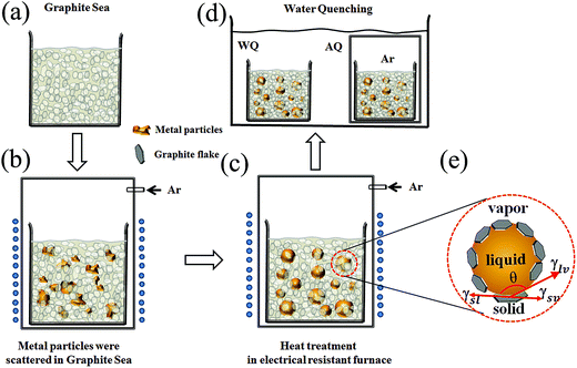
Amorphous spherical Fe78Si9B13 (numbers indicate at%) powders were fabricated by following three steps, as shown in the schematic in Fig. 1: (1) the Fe78Si9B13 raw powder (10–40 μm) prepared by jet milling amorphous ribbons was scattered in graphite powder (50–400 nm) (shown in Fig. 1(a) and (b)) via mechanical mixing for approximately 30 min, with an Fe78Si9B13 raw powder to graphite powder mass ratio of 1![[thin space (1/6-em)]](https://www.rsc.org/images/entities/char_2009.gif) :
:![[thin space (1/6-em)]](https://www.rsc.org/images/entities/char_2009.gif) 1. (2) Furthermore, the resistance furnace was preheated to the target temperature, and the mixtures were rapidly heated for approximately 60 seconds to 1493 K above the liquid phase temperature and maintained for 5 min in the resistance furnace under an argon atmosphere (Fig. 1(c)). (3) The spherical powders were quickly water quenched to room temperature and collected by ultrasonication in an aqueous solution. The water quenching approach of the spherical powder was that the one powder was sealed in a quartz tube with 0.05 MPa pure argon and then quenched in water (noted FeSiB-AQ), and the other was directly exposed to water (noted FeSiB-WQ), which is shown in Fig. 1(d). Our study primarily used graphite powder as the solid powder material due to its chemical stability at high temperature, low density, easy separation from the metal powder, and low cost. Moreover, it exhibits de-wetting for most metals such as Cu, Ag, Au and Ag–Sn.17–19 The surface morphology of the obtained spherical powder was characterized using a scanning electron microscope (SEM, Hitachi S3400, Japan), which was equipped with an energy dispersive spectrometer (EDS) for compositional analysis. The carbon content was measured using a carbon/sulfur analyzer (CS-844, LECO). The as-prepared spherical samples were mounted in cold epoxy and mechanically polished in order to obtain cross-section SEM micrographs. XRD patterns were recorded on an X-ray diffractometer (Bruker D8, Bruker, Germany) with Cu-Kα radiation (λ = 1.5406 Å) in a scattering angular range 2θ of 15–80°. The saturation magnetization from M–H loops at room temperature was measured using a vibrating sample magnetometer (VSM) with a maximum applied field of 9 kOe.
1. (2) Furthermore, the resistance furnace was preheated to the target temperature, and the mixtures were rapidly heated for approximately 60 seconds to 1493 K above the liquid phase temperature and maintained for 5 min in the resistance furnace under an argon atmosphere (Fig. 1(c)). (3) The spherical powders were quickly water quenched to room temperature and collected by ultrasonication in an aqueous solution. The water quenching approach of the spherical powder was that the one powder was sealed in a quartz tube with 0.05 MPa pure argon and then quenched in water (noted FeSiB-AQ), and the other was directly exposed to water (noted FeSiB-WQ), which is shown in Fig. 1(d). Our study primarily used graphite powder as the solid powder material due to its chemical stability at high temperature, low density, easy separation from the metal powder, and low cost. Moreover, it exhibits de-wetting for most metals such as Cu, Ag, Au and Ag–Sn.17–19 The surface morphology of the obtained spherical powder was characterized using a scanning electron microscope (SEM, Hitachi S3400, Japan), which was equipped with an energy dispersive spectrometer (EDS) for compositional analysis. The carbon content was measured using a carbon/sulfur analyzer (CS-844, LECO). The as-prepared spherical samples were mounted in cold epoxy and mechanically polished in order to obtain cross-section SEM micrographs. XRD patterns were recorded on an X-ray diffractometer (Bruker D8, Bruker, Germany) with Cu-Kα radiation (λ = 1.5406 Å) in a scattering angular range 2θ of 15–80°. The saturation magnetization from M–H loops at room temperature was measured using a vibrating sample magnetometer (VSM) with a maximum applied field of 9 kOe.
 | ||
| Fig. 1 Schematic of (a) a solid graphite powder medium as graphite sea condition, (b) raw alloy powder was scattered in the graphite sea, (c) heat treatment of the mixture in a resistance furnace under argon atmosphere, (d) water quenching, and (e) the triple solid–liquid–vapor junction of the metal droplet on a graphite flake.16 | ||
3. Results and discussion
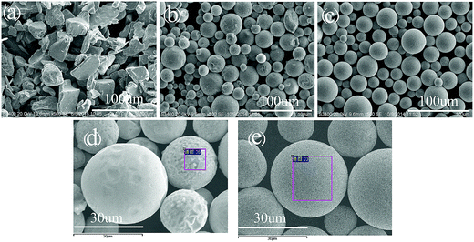
Fig. 2 shows the SEM micrographs of the raw and the fabricated Fe78Si9B13 powders. Compared to the raw powder, which has irregular shapes (such as sharp edges and corners), the as-fabricated powders exhibited a good spherical shape (shown in Fig. 2(b) and (c)). The size of the spherical particles, as well as the raw powders, is 10–40 μm.Fig. 3 shows the nominal composition of the raw and the fabricated Fe78Si9B13 powders via EDS. It can be observed that an amount of carbon was detected on the surface of the spherical particles, whereas boron could not be detected due to its low scattering factor.
 | ||
| Fig. 3 Energy dispersive spectra (EDS) of (a) the raw powder, (b) FeSiB-WQ sample and (c) FeSiB-AQ sample marked by the region in the box in Fig. 2d and e, respectively. | ||
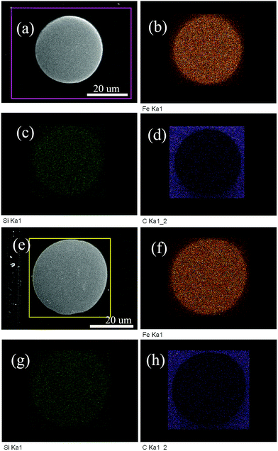
Fig. 4 shows the cross-sectional micrographics of the FeSiB-WQ and the FeSiB-AQ sample. It can be seen that the spherical particles are fully dense without pores. Regardless of the surface profile of the spherical particles, there are hardly any bulk inclusions. In addition, the liquid Fe78Si9B13 alloy de-wets from the graphite surface, which implies the feasibility of this strategy using graphite as a solid dispersant to segregate the raw material particles.
 | ||
| Fig. 4 Cross-sectional SEM micrographs and element mapping of (a)–(d) the FeSiB-WQ sample and (e)–(h) the FeSiB-AQ sample. | ||
In fact, the wetting or de-wetting of the liquid alloy on a solid medium surface depends on complicated factors such as the metal–metalloid interaction strength, surface energy, mixing energy and mixing entropy. In a nonreactive system, the high liquid metal surface energy draws into itself on contact with the smaller surface energy of graphite to decrease the system's free energy. As shown in Fig. 1(e), the equilibrium contact angle can be primarily described by Young's equation:
 | (1) |
However, in a reactive system, the carbide reactant at the interface or from carburization in the liquid metal makes the droplet less spherical. The equilibrium contact angle is furthermore described as follows:20
 | (2) |
The reaction will spread the wetting line as governed by the system's free energy decrease. The greater the free energy of the reaction, the greater the wetting will occur. For example, although the surface tension of pure Fe is 1850 mJ m−2 at the melt point, the contact angle on graphite is only about 50° with the precipitation of carbide.20 Similar results were displayed by transition metals from Ti to Ni, which exhibited the highest degree of graphite wettability due to the strong reaction with graphite in the liquid state to form carbides or case carburization.12,21
However, if the interfacial reaction is inhibited, it is possible to synthesize smooth spherical Fe-based alloy particles, especially because the low level bulk surface segregation impurities build up to block the reaction of the interface between the alloy and graphite.19 Furthermore, the surface impurities would segregate the molten alloy surface and suppress wetting of the alloy to the graphite substrate. The reason for the spheroidization of FeSiB may be that the surface carbides inhibit the interfacial reaction and suppress the wetting of the FeSiB alloy to the graphite substrate. Similar reports indicate that the liquid Ni55B45 eutectic alloy exhibits the de-wetting of graphite with a contact angle of 130°, which is only 45° for pure molten Ni wetting of a graphite substrate.19 From EDS (shown in Fig. 3), it was found that the carbon concentration is about 9.2 wt% and 5.2 wt% for the FeSiB-WQ and FeSiB-AQ sample, respectively, which suggest that the surface impurities were carbides. Furthermore, accurate carbon analysis of the FeSiB-WQ powder using a CS-844 carbon/sulfur analyzer confirmed that the content is less than 1.73 wt%. It can also be noted that different spherical morphologies via the different cooling approaches are clearly observed. The spherical particles of the FeSiB-AQ sample exhibit a smooth surface, whereas the FeSiB-WQ sample contract and crinkle upon direct exposure to water. Obviously, as shown in the high magnification SEM images (shown in Fig. 2(d) and (e)), the impurities are segregated and concentrated in homogeneously on the surface of the FeSiB-WQ sample due to the solidification of the molten alloy and the water shock. In situ separation between the alloy particle and graphite may occur and the carbides mainly enrich on the surface depending on the different surface carbon contents. In addition, as an incidental benefit, the surface carbides are treated as the electrical insulation coatings.
Fig. 5 shows the X-ray diffraction patterns of the raw and the spherical Fe78Si9B13 powders. The characteristic peak of α-Fe was clearly seen in the amorphous hump of raw powder that was prepared by jet milling amorphous ribbons. The XRD pattern of the FeSiB-WQ sample is typical of the amorphous hump in Fig. 5(b). The crystal and amorphous mixed phase indicates that the amorphous forming ability of the Fe-based alloy was limited just by water quenching. However, one could suppose that the amorphous degree of the spherical FeSiB-WQ powder had been improved with decrease in the α-Fe phase. Since the main crystalline product of the Fe-based amorphous alloy was α-Fe, the primary cluster of amorphous state could be regarded as the deviation of α-Fe clusters.1 Thus, dissolution of B and Si in the Fe lattice occurred when the raw amorphous Fe78Si9B13 particles re-melted under high temperature. Furthermore, after directly quenching in water, the Fe–B phase induced from the α-Fe clusters could be found in the evolution of XRD pattern in Fig. 5(b). The XRD of the FeSiB-AQ sample in Fig. 5(c) shows a more complex crystallization phase with B(Fe, Si)3 phase (JCPDS no. 19-0625) due to the poor cooling rate even though the remelting process was depleted of partial α-Fe. One important reason for this is that the heat capacity and conductivity of the Ar gas sealed in the quartz-tube is poorer than that of water.
 | ||
| Fig. 5 XRD patterns of (a) the raw powder, (b) FeSiB-WQ spherical powder, and (c) FeSiB-AQ spherical powder. | ||
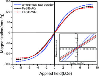
Fig. 6 shows the magnetic hysteresis loop of the spherical Fe78B9Si13 alloy powders at room temperature. The magnetic parameters are listed in Table 1. The raw sample exhibited the largest magnetization and coercivity, which were determined by the magnetization of the amorphous phase and the α-Fe component. However, the magnetization of the spherical FeSiB-WQ powder was the smallest. Due to the fact that the magnetic property is sensitive to the phase composition and the crystalline microstructure,22 the presence of non-magnetic oxides or carbides on the surface of the spherical Fe–Si–B powder could also have a bad effect on its magnetic properties by decreasing its saturation magnetization. When Si or B was alloyed with Fe, the change in the nearest neighbor configuration would also result in the reduction of the magnetic moment per atom, and therefore it reduces the magnetization and coercivity. Comparatively, the coercivity of FeSiB-AQ was relatively higher than that of the FeSiB-WQ sample. This may be attributed to the B(Fe, Si)3 phase (confirmed by XRD in Fig. 5(c)), which was a harden magnetic phase with high magnetic anisotropy.
 | ||
| Fig. 6 M–H hysteresis loop curve of the raw and spherical powder under different cooling approaches, inset: enlarged view of the coordinate. | ||
| Samples | Ms (emu g−1) | Hc (Oe) |
|---|---|---|
| Raw powder | 163 | 22.7 |
| FeSiB-AQ | 159.2 | 31.5 |
| FeSiB-WQ | 145 | 2.8 |
4. Conclusions
Spherical Fe-based magnetic powders were successfully fabricated via the liquid–solid interface method. The surface morphology of the particles confirms that an Fe-based alloy can be spheroidized on a graphite sea. Low level surface impurities reside on the surface of the spherical Fe-based alloy particles to suppress the wetting of the alloy on graphite. The cross-sectional micrographics of the spherical particles indicate that the particles are fully dense without pores and bulk inclusions. In addition, the differences in spherical morphological indicate that the FeSiB-AQ sample exhibits a smooth surface, whereas the FeSiB-WQ sample has a contracted and crinkled surface. The amorphous degree of the spherical FeSiB-WQ powder directly exposed to water was improved compared to that of the raw materials. The magnetic characteristics of the spherical powder quenched directly in water exhibit excellent soft magnetic properties. Our strategy is expected to provide a new route for the fabrication of spherical Fe-based magnetic powders, which can serve in the functional application of powder metallurgy.Acknowledgements
This study was supported by the National Key Project of Fundamental Research of China (Grant No. 2012CB932304).References
- J. Zhang, Z. Zheng and C. H. Shek, J. Appl. Phys., 2014, 115, 233912 CrossRef.
- I. Otsuka, T. Kadomura, K. Ishiyama and M. Yagi, IEEE Trans. Magn., 2009, 45, 4294–4297 CrossRef CAS.
- Y. B. Kim and K. Y. Kim, IEEE Trans. Magn., 2006, 42, 2802–2804 CrossRef CAS.
- X. Li, A. Makino, H. Kato, A. Inoue and T. Kubota, Mater. Sci. Eng., B, 2011, 176, 1247–1250 CrossRef CAS.
- Y. Liu, S. Niu, F. Li, Y. Zhu and Y. He, Powder Technol., 2011, 213, 36–40 CrossRef CAS.
- M. Yagi, I. Endo, I. Otsuka, H. Yamamoto, R. Okuno, H. Koshimoto and A. Shintani, J. Magn. Magn. Mater., 2000, 215, 284–287 CrossRef.
- S. Nakahara, E. A. Périgo, Y. Pittini-Yamada, Y. de Hazan and T. Graule, Acta Mater., 2010, 58, 5695–5703 CrossRef CAS.
- S. Dong, B. Song, X. Zhang, C. Deng, N. Fenineche, B. Hansz, H. Liao and C. Coddet, J. Alloys Compd., 2014, 584, 254–260 CrossRef CAS.
- I. Otsuka, K. Wada, Y. Maeta, T. Kadomura and M. Yagi, IEEE Trans. Magn., 2008, 44, 3891–3894 CrossRef CAS.
- A. Miura, W. Dong, M. Fukue, N. Yodoshi, K. Takagi and A. Kawasaki, J. Alloys Compd., 2011, 509, 5581–5586 CrossRef CAS.
- A. E. Berkowitz, H. Harper, D. J. Smith, H. Hu, Q. Jiang, V. C. Solomon and H. B. Radousky, Appl. Phys. Lett., 2004, 85, 940 CrossRef CAS.
- P. Wynblatt, Acta Mater., 2000, 48, 4439–4447 CrossRef CAS.
- A. Habenicht, M. Olapinski, F. Burmeister, P. Leiderer and J. Boneberg, Science, 2005, 309, 2043–2045 CrossRef CAS PubMed.
- M. Fuentes-Cabrera, B. H. Rhodes, J. D. Fowlkes, A. López-Benzanilla, H. Terrones, M. L. Simpson and P. D. Rack, Phys. Rev. E, 2011, 83, 041603 CrossRef PubMed.
- A. L. Giermann and C. V. Thompson, Appl. Phys. Lett., 2005, 86, 121903 CrossRef.
- C. Lei, H. Huang, Z. Cheng, S. Tang and Y. Du, Appl. Surf. Sci., 2015, 357, 167–171 CrossRef CAS.
- Z. Weltsch, A. Lovas, J. Takács, Á. Cziráki, A. Toth and G. Kaptay, Appl. Surf. Sci., 2013, 268, 52–60 CrossRef CAS.
- D. A. Mortimer and M. Nicholas, J. Mater. Sci., 1970, 5, 149–155 CrossRef CAS.
- M. J. Bozack, A. E. Bell and L. W. Swanson, J. Phys. Chem., 1988, 92, 3925–3934 CrossRef CAS.
- C. Wu and V. Sahajwalla, Metall. Mater. Trans. B, 1998, 29, 471–477 CrossRef.
- L. Yang, P. Shen, Q. Lin, F. Qiu and Q. Jiang, Mater. Chem. Phys., 2010, 124, 499–503 CrossRef CAS.
- S. Alleg, M. Ibrir, N. E. Fenineche, S. Azzaza, R. Bensalem and J. J. Suñol, J. Alloys Compd., 2010, 494, 109–115 CrossRef CAS.
| This journal is © The Royal Society of Chemistry 2016 |

