 Open Access Article
Creative Commons Attribution 3.0 Unported Licence
Enhancing the oxygen evolution reaction activity of CuCo based hydroxides with V2CTx MXene†
Bastian
Schmiedecke
a,
Bing
Wu
b,
Thorsten
Schultz
cd,
Aline Alencar
Emerenciano
a,
Namrata
Sharma
e,
Danielle A.
Douglas-Henry
f,
Apostolos
Koutsioukis
f,
Mehmet Turan
Görüryılmaz
 a,
Valeria
Nicolosi
 f,
Tristan
Petit
 e,
Norbert
Koch
cd,
Zdenek
Sofer
b and
Michelle P.
Browne
 *a
*a
aHelmholtz Young Investigator Group Electrocatalysis: Synthesis to Devices, Helmholtz-Zentrum Berlin für Materialien und Energie GmbH, Albert-Einstein-Str. 15, 12489 Berlin, Germany. E-mail: Michelle.browne@helmholtz-berlin.de
bDepartment of Inorganic Chemistry, University of Chemistry and Technology, Prague, Technická 5, 166 28 Prague 6, Czech Republic
cHelmholtz-Zentrum Berlin für Materialien und Energie GmbH, Berlin, 14109, Germany
dInstitut für Physik & IRIS Adlershof, Humboldt-Universität zu Berlin, Berlin, 12489, Germany
eYoung Investigator Group Nanoscale Solid–Liquid Interfaces, Helmholtz-Zentrum Berlin für Materialien und Energie GmbH, Albert-Einstein-Str. 15, 12489 Berlin, Germany
fSchool of Chemistry, CRANN and AMBER Research Centres, Trinity College Dublin, College Green, Dublin D02 PN40, Ireland
First published on 2nd August 2024
Abstract
The oxygen evolution reaction (OER) is a key reaction in the production of green hydrogen by water electrolysis. In alkaline media, the current state of the art catalysts used for the OER are based on non-noble metal oxides. However, despite their huge potential as OER catalysts, these materials exhibit various disadvantages including lack of stability and conductivity that hinder the wide-spread utilization of these materials in alkaline electrolyzer devices. This study highlights the innovative chemical functionalization of a mixed copper cobalt hydroxide with the V2CTx MXene to enhance the OER efficiency, addressing the need for effective electrocatalytic interfaces for sustainable hydrogen production. The herein synthesized CuCo@V2CTx electrocatalysts demonstrate remarkable activity, outperforming the pure CuCo catalysts for the OER and moreover show increased efficiency after 12 hours of continuous operation. This strategic integration improved the water oxidation performance of the pure oxide material by improving the composite's hydrophilicity, charge transfer properties and ability to hinder Cu leaching. The materials were characterized using an array of materials characterization techniques to help decipher both structure of the composite materials after synthesis and to elucidate the reasoning for the OER enhancement for the composites. This work demonstrates the significant potential of TMO-based nanomaterials combined with V2CTx for advanced innovative electrocatalytic interfaces in energy conversion applications.
1. Introduction
Electrochemical water splitting, when combined with solar or wind technologies, is one potential route to make an alternative green fuel (i.e. green H2) to replace fossil derived fuels (e.g. oil, coal and gas) to power our buildings, vehicles or for feedstocks for important synthetic processes, such as the generation of ammonia through the Haber-Bosch process.1 During water splitting, H2 is produced at the cathode and is denoted as the hydrogen evolution reaction (HER). However, it is the anodic reaction, the oxygen evolution reaction (OER), which is the most energy intensive reaction during the water splitting process, as four electrons need to be transferred to generate one molecule of O2 while the cathodic reaction needs only two electrons to produce H2.2 Therefore, to make the overall process of water splitting more efficient, the OER needs to become less energy demanding.1Currently, for the OER, the most studied catalysts in alkaline media, or for anion exchange membrane electrolyzers (AEMELs), are based on non-noble metals such as Ni and Co materials. However, these materials suffer from low conductivity and a loss in stability over time, which are essential prerequisites of an OER catalyst. There have been various studies to mix conductive aids with non-noble metal materials, however, the aids used are predominantly based on pure carbon materials such as graphene or carbon nanotubes.3 It has been shown that these carbon based materials somewhat corrode in alkaline environments (although not as corrosive as in acidic media) and can also contain metal impurities.4,5 Furthermore, the utilization of pure carbon supports has shown to decrease the faradaic efficiency of metal oxide materials for the OER and decrease the stability of the metal oxide compared to the same oxide on other supports.6,7 Recently, there have been reports emerging on utilising MXene materials as a conductive aid/support for OER catalysts.8
MXenes are a relatively new family of 2D materials, which are made up of transition metal carbides and nitrides, produced from MAX phases by various etching processes.9 A MAX phase has the general formula of Mn+1AXn where the M is an early transition metal, the A is an element from group 13 or 14 of the periodic table, and the X represents a carbon or nitrogen. During the etching process, carried out in a fluoride ion based solution, the A-element is removed from the MAX structure, causing the carbide layers to become terminated by OH−, O−, Cl− or F− groups, which are subsequently called ‘edge sites’.10 The resulting structure is known as ‘MXene’ with the most common/first synthesised MXene being Ti3C2Tx.9,10 MXenes are known to be highly conductive, hydrophilic and mechanically durable due to their structures, which are essential properties for OER catalysts.9 However, to date MXenes are not known to contain active sites for the OER, as no MXenes with metals for promoting the OER have been successfully synthesised (e.g. Ni, Co).11,12
Furthermore, these edge sites on the MXenes are extremely important. The edge sites can be engineered/tailored to alter the materials inherent properties and therefore the conductivity, hydrophilicity, and the thermodynamic stability of the material is controllable. However, these edge sites can easily oxidise even in air, which results in the breakdown of the material into its respective oxide, e.g. Ti3C2Tx will oxidise into TiO2, which in turn leaves a material with reduced conductivity and hydrophilicity. Additionally and more importantly, it has been previously shown that Ti3C2Tx oxidises rapidly under OER conditions to TiO2 hence, this material alone is not an appropriate OER catalyst.13 However, there are many strategies being developed to block or ‘cap’ these edge sites to hinder or slow down the oxidation process.
One way to engineer the edge sites for the OER is to use active OER materials, first row inexpensive MOx, such as Ni, Fe, Co and Mn, and anchor them onto the MXene edge sites in order to hinder the oxidation process. There have been multiple reports on the manipulation of Ti3C2Tx with metal hydroxides/oxides which show an increase in the OER for the metal oxide/Ti3C2Tx composite.13–17 For example, Benchakar and co-workers have reported that a cobalt layered double hydroxide (Co-LDH)/Ti3C2Tx material synthesised by a solvothermal synthesis results in the promotion of the OER by 50 mV when compared to the pure Co-LDH catalysts in alkaline electrolyte.14 To date, there are only few reports on OER metal oxide catalysts with other MXene materials.18,19 In one recent study, Rogach et al. compare the OER activity of three different MXene supports (Ti3C2Tx, V2CTx and NbCTx) with Co single atoms made by an ice photo-reduction route.19 This study reveals that the V2CTx with Co single atoms exhibits the lowest OER overpotentials, however, over a period of 10 hours, this composite results in a loss of activity. The authors postulate from experimental and theoretical studies that the superior OER capabilities of the V2CTx are attributed to the re-distribution of the electronic structure of the Co atoms due to a higher rate of electron transfer.19 Furthermore, various studies have suggested that the OER performance of Co oxides can be improved by the addition of Cu into its structure in alkaline media.20,21 For example, Scott and co-workers demonstrated that CuCo oxides outperformed Co oxides in a three electrode cell and in an AEMEL device.20 Recently, Alishahi and team synthesised a CuCo and a CuCo/Ti3C2Tx (MXene) catalyst for alkaline OER, which exhibited overpotentials at 10 mA cm−2 of 470 and 380 mV, respectively.22 This study showed that the addition of the most common MXene, Ti3C2Tx, is effective in improving the OER activity of a CuCo based material. To our knowledge, the effect of V2CTx, the material when combined with Co single atoms showed the best OER performance compared to the same Co single atoms on Ti3C2Tx, on the OER properties of CuCo materials has not been investigated.19
In this work, a range of novel CuCo based V2CTx composites are fabricated through a hydrothermal route and investigated for the OER. The V2CTx amount varies in the composite materials to determine the effect of the MXene content on the OER. These materials are characterized by a suite of techniques to determine the surface and bulk chemical composition before and after the OER, which allows for changes in the chemical composition to be attributed for changes in the OER performance of pure CuCo and MXene composite materials.
2. Material and methods
2.1. Materials and chemicals
The materials and chemicals used in the current study were a graphite rod (redox.me), a mercury–mercury oxide (Hg/HgO) reference electrode (redox.me), a glassy carbon disc electrode (ALS instruments) and Nafion (Sigma Aldrich). Sodium hydroxide pellets (≥98%, reagent-grade), ethanol (≥99%, reagent-grade), isopropanol (≥99%, reagent-grade), Co(CH3COO)2·4H2O (≥99% metal basis, M of 249.08 g mol−1), Cu(CH3COO)2·H2O (≥99% metal basis, M of 199.65 g mol−1), V2AlC MAX phase (Jinzhou Haixin Metal Materials, China), NaF (Lachner), HCl (Lachner), TBAOH (Sigma-Aldrich) and urea (≥99%, ACS reagent, M of 60.06 g mol−1) were purchased from Sigma-Aldrich. For sample preparation and dilutions, ultrapure water with a resistivity of 18.2 MΩ cm was used.2.2. Preparation of V2CTx
The exfoliated V2CTx MXene was prepared by removing the Al layer from its MAX phase V2AlC using a mixed HCl + NaF etching solution. The detailed experimental process is as follows: 4.5 g of NaF was stirred and dissolved in 60 ml of distilled water, followed by the addition of 60 ml of concentrated hydrochloric acid. Next, 5 g of V2AlC MAX phase was slowly added to the above solution and stirred for 1 hour under an atmospheric environment until no obvious bubbles were generated. The mixture was then sealed in a stainless-steel autoclave with a Teflon liner. The mixture was continuously stirred in a 90 °C oil bath for 3 days. Due to the difficulty in completely removing Al from the MAX phase, the solid product from the first etching was subjected to the same etching steps again. The product was then centrifuged three times with distilled water to obtain an etched precursor. Subsequently, the precursor was stirred in 20 ml of 20% TBAOH solution for 24 hours for exfoliation, and then diluted to a 100 ml suspension and stirred for an additional 24 hours. The suspension was centrifuged at 10![[thin space (1/6-em)]](https://www.rsc.org/images/entities/char_2009.gif) 000 rpm and washed three times with an ethanol/water solution in a 1
000 rpm and washed three times with an ethanol/water solution in a 1![[thin space (1/6-em)]](https://www.rsc.org/images/entities/char_2009.gif) :
:![[thin space (1/6-em)]](https://www.rsc.org/images/entities/char_2009.gif) 4 ratio to remove residual TBAOH. Finally, centrifugation at 1000 rpm was used to remove unetched MAX phase or other solid impurities. This process yielded well-exfoliated V2CTx MXene for further use.
4 ratio to remove residual TBAOH. Finally, centrifugation at 1000 rpm was used to remove unetched MAX phase or other solid impurities. This process yielded well-exfoliated V2CTx MXene for further use.
2.3. Preparation of CC1, CC10, CC25, CC50 and the pure Cu, Co and CuCo materials
CuCo@V2CTx was synthesized through a urea-assisted hydrothermal method. In a typical synthesis process, V2CTx was used from a colloidal solution (1.47 mg ml−1) and then, 5 mmol urea, 1 mmol Cu(CH3COO)2·H2O and 2 mmol Co(CH3COO)2·4H2O were added to the solution, and it was stirred for 30 minutes to fully dissolve all the compounds. The solution was transferred into a Teflon-lined stainless-steel autoclave and kept at 120 °C for 6 h for hydrothermal treatment. After cooling down to room temperature, the precipitate was collected by centrifugation at 5000 rpm for 10 min, and then repeatedly washed with deionized water (3×) and ethanol (3×). The sediment was dried at 60 °C for 10 h. The collected powder samples were labelled as CC1, CC10, CC25, and CC50, for 1, 10, 25, and 50 molar mass% V2CTx content, respectively. The pure materials, labelled pure Co, pure Cu and pure CuCo, were synthesized using the same method without addition of V2CTx.2.4. Electrochemical measurements
The electrochemical performance of the materials was characterized in a standard three-electrode cell in alkaline aqueous solution at RT. 1.0 M NaOH was used as electrolyte, prepared from NaOH pellets. A standard mercury–mercury oxide electrode (mercury/mercury oxide Hg/HgO) was employed as a reference electrode (RE) and a graphite rod as a counter electrode (CE). The working electrode was a 3 mm diameter glassy carbon (GC) disk with a geometric surface area of 0.0707 cm2. The cell was connected to an electrochemical workstation (PalmSens) and a rotating ring disc electrode (RRDE, ALS-Japan).A catalytic ink was prepared for every material by dispersing 10 mg of catalytic powder in 1 ml DI water/isopropanol solution (1![[thin space (1/6-em)]](https://www.rsc.org/images/entities/char_2009.gif) :
:![[thin space (1/6-em)]](https://www.rsc.org/images/entities/char_2009.gif) 1) and 8 μL Nafion. The solution was ultrasonicated for 10 min to form a homogenous ink. To reach a catalyst loading of 1.6 mg cm−2, 11.3 μL ink was deposited onto the polished GC disk and allowed to dry in air at RT. All measurements were performed in nitrogen saturated 1 mol L−1 NaOH electrolyte. Cyclic voltammetry (CV) profiles and linear sweep voltammetry (LSV) data were acquired between the potential ranges −0.2 and 0.6 V vs. RHE and 0.0 V and 0.85 V vs. RHE, respectively. First, each catalyst was subjected to 8 CV cycles in the potential range at a scan rate of 40 mV s−1. Polarization and Tafel plot measurements were performed at a scan rate of 1 mV s−1 and a rotation rate of 1600 rpm. To determine the resistance of the cell, electrochemical impedance spectroscopy (EIS) was recorded in a frequency range between 1 Hz and 1 mHz, with an oscillation amplitude of 10 mV in a non-faradaic region. To determine the charge transfer resistance of the materials under operation, EIS measurements were conducted in the OER region at 1.6 V vs. RHE. To test the long term stability of the catalyst, chronopotentiometry was executed at a constant current density of 10 mA cm−2 for various times.
1) and 8 μL Nafion. The solution was ultrasonicated for 10 min to form a homogenous ink. To reach a catalyst loading of 1.6 mg cm−2, 11.3 μL ink was deposited onto the polished GC disk and allowed to dry in air at RT. All measurements were performed in nitrogen saturated 1 mol L−1 NaOH electrolyte. Cyclic voltammetry (CV) profiles and linear sweep voltammetry (LSV) data were acquired between the potential ranges −0.2 and 0.6 V vs. RHE and 0.0 V and 0.85 V vs. RHE, respectively. First, each catalyst was subjected to 8 CV cycles in the potential range at a scan rate of 40 mV s−1. Polarization and Tafel plot measurements were performed at a scan rate of 1 mV s−1 and a rotation rate of 1600 rpm. To determine the resistance of the cell, electrochemical impedance spectroscopy (EIS) was recorded in a frequency range between 1 Hz and 1 mHz, with an oscillation amplitude of 10 mV in a non-faradaic region. To determine the charge transfer resistance of the materials under operation, EIS measurements were conducted in the OER region at 1.6 V vs. RHE. To test the long term stability of the catalyst, chronopotentiometry was executed at a constant current density of 10 mA cm−2 for various times.
3. Results & discussion
3.1. Structural characterization
In this work, the targeted CuCo/V2CTx composites were fabricated by a two-step urea assisted hydrothermal process, Fig. 1A. In the first step of the process, the V2CTx (MXene) was produced by etching the V2AlC by in situ exfoliation with NaF and HCl to produce multi-layer V2CTx which was then delaminated to achieve V2CTx. The composites were then prepared by adding the different wt% amounts of V2CTx to an autoclave along with copper acetate, cobalt acetate, urea and distilled water. The reactant solutions were annealed in an oven at 120 °C for 6 hours (see experimental section for a more detailed description).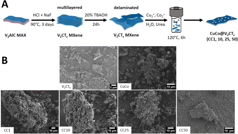 | ||
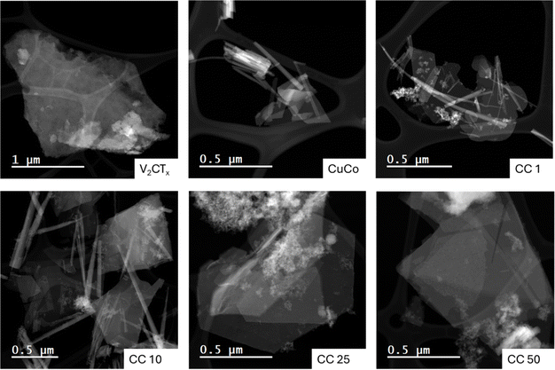
| Fig. 1 (A) Schematic of the synthesis procedure of the CuCo V2CTx composites and (B) SEM images of V2CTX, CuCo, CC1, CC10, CC25 and CC50. | ||
The concentration of V2CTx in the composite materials were 1, 10, 25 and 50 wt% and from here on the resulting composite catalysts will be denoted as CC1, CC10, CC25 and CC50, respectively. Pure Co, pure Cu and CuCo catalysts were also synthesized under the same reaction conditions but without addition of V2CTx. Hence, in total eight catalysts were made in this work. To identify the chemical and structural properties of the prepared catalysts before the OER studies, the materials were characterized by SEM, XRD, and XPS.
SEM was carried out on the various catalysts to determine their morphological characteristics, Fig. 1B. The V2CTx exhibits typical flake-like dimensions seen for delaminated MXenes, while the pure CuCo is composed of aggregated material. The CuCo/V2CTx composite materials aggregated material is predominantly found around the flake-like structures from the V2CTx. The composite materials do not resemble the morphologies of the pure Co or Cu -based materials. The pure Co material exhibits a coarse leaf-like morphology, and the pure Cu material has a spherical shape morphology (Fig. S1†).
To get a more in-depth account of the morphology and elemental composition of the pure and composite materials, scanning transmission electron microscopy (STEM) with energy dispersive X-ray spectroscopy (EDS) mapping was carried out, Fig. 2 and S2–S7.† The STEM image of the V2CTx confirms the flake morphology observed with the SEM and the EDS map shows that the entire flake consists of vanadium, Fig. S2.† The CuCo STEM image, Fig. 2, shows that the aggregated material observed in the SEM consists of flake and rod-like structures. From the EDS maps of the CuCo sample, Fig. S3,† the Co and Cu are present in both structures. For the CC1 and CC10 materials, both contain flake and rod-like morphologies. The rod-like structures contain a good distribution of Cu, Co and V while the flakes have a higher distribution of Co when compared to Cu and V from the EDS mapping in Fig. S4 and S5.† From the STEM images in Fig. 2 of the CC25 and CC50, it is evident that a foam-like structure is present which is less prominent in the other composites. From the EDS maps in Fig. S6 and S7† for the CC25 and CC50 materials, this foam structure contains a higher concentration of V with the Cu and Co compared to the rod or flake structures present.
X-Ray diffraction of the pure and composite catalysts was carried out to determine the crystal structure and to determine if the addition of the V2CTx to the CuCo had any effects on the composites final structure, Fig. 3. The pure Co catalyst can be predominantly indexed to cobalt carbonate hydroxide (ICDD: 04-024-2126, Fig. 3A). The pure Co material exhibits major peaks at 14.5, 17.4, 24.0, 32.3 and 34.6° which corresponds to the (020), (021), (022), (023), (102) and (023) reflections of the Co2(CO3)(OH)2 while the peak at about 24.8° indicates the presence of another Co2(CO3)(OH)2 phase i.e. Co(CO3)0.5OH·0.11H2O.23 Furthermore, the major diffraction peaks at 14.8, 17.4, 24.0, 34.6, 35.4, 36.5 and 38.4° for the mixed CuCo material can be referenced to the (020), (120), (220), (031), (240), (330) and the (150) planes of the mineral Kolwezite (Cu+2, Co)2(CO3)(OH)2, Fig. 3A (ICDD: 00-029-1416). The additional peaks at 2Theta values of ∼10, 27 and 34° may again indicate the presence of Co(CO3)0.5OH·0.11H2O in the material.23
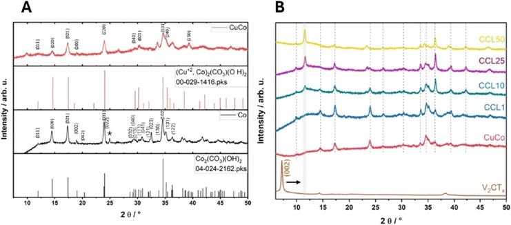 | ||
| Fig. 3 (A) XRD pattern of pure Co and pure CuCo (B) XRD pattern of V2CTX, CuCo, CC1, CC10, CC25 and CC50. (* = peak not in corresponding reference pattern). | ||
From Fig. 3B, in relation to the Kolwezite peaks in the composite materials, there are also some shifts in the 2theta positions and the intensity of the peaks which shows that the V2CTx is influencing the Kolwezite crystal structure. For example, the Kolwezite (220) and (031) reflection at 24 and 35.4°, respectively, decreases with increasing V2CTx. Furthermore, the (220) reflection at 24° changes significantly upon subsequent V2CTx additions for the materials CC10-50. For the CC10, this peak is lower in intensity compared to CC1, then the peak for the CC25 splits into two peaks and then for CC50, only the newer peak at the lower 2theta value is present.
Furthermore, the diffraction pattern of the pure V2CTx shows that the V2AlC was fully etched and delaminated into the MXene counterpart from the presence of the strong (002) and the (004) reflections at 7.2° and 14.4°.24,25 The peak at 37.8° may be associated with LiF residue left over from the etching procedure.24 The XRD patterns of the CC1-50 are present in Fig. 3B and all show reflections associated with both Kolwezite and the V2CTx, however, some diffraction peaks are altered compared to the pure materials. The (002) peak of the V2CTx in the composites (CC1-50) is shifted to a higher 2theta value of 11.5°, indicating a reduction in the interlayer spacing, possibly due to re-stacking of the single V2CTx flakes upon drying.26,27 Additionally, the presence of vanadium oxide materials in the bulk of the composites can also be ruled out as there are no additional reflections associated to V2O3, V2O5 or V3O8 in the XRD patterns.24
XANES at the V L edge and O K edge (Fig. 4) were acquired on single flakes of the pure V2CTx and the CC50 using STXM (Fig. S8A and B†). STXM is based on transmission detection which is sensitive to the bulk of probed MXene flakes.28 For the pure V2CTx and the CC50 materials, the V L-edge consists of 2 major peaks corresponding to L3 and L2-edge at 517.6 eV and 524 eV respectively. These peaks are associated with the electronic transitions from the V 2p3/2 and 2p1/2 core levels to the 3d orbital. Hence, crystal field splitting of 3d orbital gives rise to t2g and eg orbitals for both edges (Fig. 4). Fig. S2† shows the chemical map of V2CTx and CC50 measured at 517 eV peak absorption energies for V L3 edge. A comparison of the V L3 edge t2g/eg intensity ratio shows that there are no significant changes in V oxidation state between the pure V2CTx (t2g/eg intensity ratio: 1![[thin space (1/6-em)]](https://www.rsc.org/images/entities/char_2009.gif) :
:![[thin space (1/6-em)]](https://www.rsc.org/images/entities/char_2009.gif) 0.60) and the CC50 (t2g/eg intensity ratio: 1
0.60) and the CC50 (t2g/eg intensity ratio: 1![[thin space (1/6-em)]](https://www.rsc.org/images/entities/char_2009.gif) :
:![[thin space (1/6-em)]](https://www.rsc.org/images/entities/char_2009.gif) 0.62) material. This would indicate that the V2CTx is not altered in the CC50 materials. For V2CTx the O K pre-edge originates from electronic transitions from O 1s to O 2p orbital hybridized with V 3d orbitals. Overlap of oxygen 2p and vanadium 3d orbitals results in a set of bonding and anti-bonding orbitals i.e. t2g and eg orbitals. CC50 shows similar t2g and eg orbital splitting to pure V2CTx along with an additional peak at 533.2 which could be due to the oxide layer formed by CuCo oxide over the MXene surface.
0.62) material. This would indicate that the V2CTx is not altered in the CC50 materials. For V2CTx the O K pre-edge originates from electronic transitions from O 1s to O 2p orbital hybridized with V 3d orbitals. Overlap of oxygen 2p and vanadium 3d orbitals results in a set of bonding and anti-bonding orbitals i.e. t2g and eg orbitals. CC50 shows similar t2g and eg orbital splitting to pure V2CTx along with an additional peak at 533.2 which could be due to the oxide layer formed by CuCo oxide over the MXene surface.
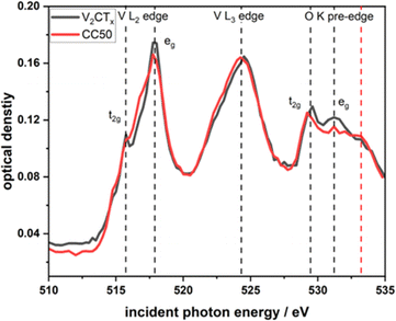 | ||
| Fig. 4 Comparative V–L edge and O–K pre-edge XANES spectra obtained from STXM of few-layered flakes of V2CTx and CC50. | ||
XPS, Fig. 5, was utilized to evaluate the surface chemistry of the pure and composite materials to assess if it differs from the bulk of the materials probed by STXM. The XPS spectra are shown in Fig. 5A and B. In relation to the pure MXene sample, the presence of the V–C peak in the C1s region at 282 eV confirms that the V2CTx structure is preserved after delamination. For the same sample, the V 2p region also confirms the presence of V2+ at a binding energy of about 513 eV, which is related to V–C bonds, and the presence of V4+ at 516 eV mostly associated to V–O bonds on the MXene surface.29 From the V 2p region, the state of the vanadium for the composites at the surface is in a V4+ state.30,31 No V2+ component is detected on the composite materials. This may be related to the short probing depth of XPS and the fact that the CuCo materials stand on top of the vanadium atoms. The surface of V2CTx is highly susceptible to oxidation and oxygen species on the surface are very common.32 The O 1s peak for the pure MXene can be fitted to three peaks at 529, 531 and 532 eV which correspond to V–O, C–V–O and V–OH bonds. The V–O bonds can be attributed to surface vanadium oxides, the C–V–O is indicative of oxygen terminated V2CTx while the V–OH may be present due to OH terminations on the V2CTx.27 The fact that no change in the vanadium oxidation state was observed from STXM, which is bulk-sensitive, confirms that the oxidation concerns mostly the top layer of the few-layered MXene flakes.
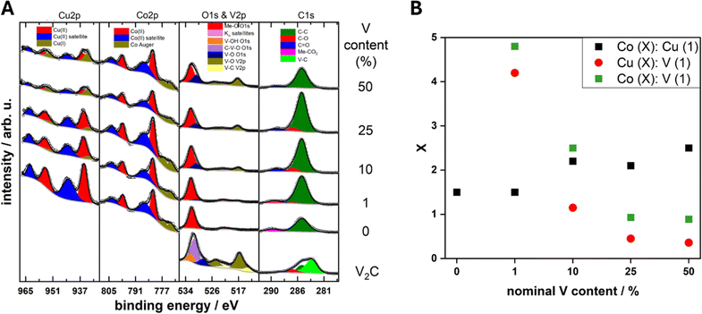 | ||
Fig. 5 (A) XPS core levels of the V2CTx, CuCo, CC1, CC10, CC25 and CC50 and (B) estimated ratios of the surface Co![[thin space (1/6-em)]](https://www.rsc.org/images/entities/char_2009.gif) : :![[thin space (1/6-em)]](https://www.rsc.org/images/entities/char_2009.gif) Cu, Cu Cu, Cu![[thin space (1/6-em)]](https://www.rsc.org/images/entities/char_2009.gif) : :![[thin space (1/6-em)]](https://www.rsc.org/images/entities/char_2009.gif) V and Co V and Co![[thin space (1/6-em)]](https://www.rsc.org/images/entities/char_2009.gif) : :![[thin space (1/6-em)]](https://www.rsc.org/images/entities/char_2009.gif) V content from XPS core level areas. V content from XPS core level areas. | ||
For the pure CuCo catalyst, the Co 2p and Cu 2p core levels correspond to Co2+ and Cu2+ due to the main peaks at 782 and 936 eV, respectively, and the characteristic satellite structure.30,33 Additionally in the C 1s region, the CuCo catalyst exhibits a metal-carbonate bond around 290 eV and a metal–oxygen peak in the O 1s region at around 532 eV, which further confirms the synthesis of a copper cobalt carbonate hydroxide. Interestingly, upon the addition of V2CTx in the composite, a partial reduction of the Cu oxidation state from Cu2+ to Cu1+ is observed at the Cu 2p core level.30 Furthermore, the amount of Cu1+ increases with the V2CTx concentration. Additionally, the ratio of Co![[thin space (1/6-em)]](https://www.rsc.org/images/entities/char_2009.gif) :
:![[thin space (1/6-em)]](https://www.rsc.org/images/entities/char_2009.gif) Cu at the surface of the composites increases with V2CTx which effectively results in the enrichment of the surface with Co2+ in comparison to the Cu2+/1+ species from the XPS, Fig. 3C. The amount of vanadium species at the surface also increases progressively with the concentration of V2CTx in the composite.
Cu at the surface of the composites increases with V2CTx which effectively results in the enrichment of the surface with Co2+ in comparison to the Cu2+/1+ species from the XPS, Fig. 3C. The amount of vanadium species at the surface also increases progressively with the concentration of V2CTx in the composite.
3.2. Electrochemical characterization
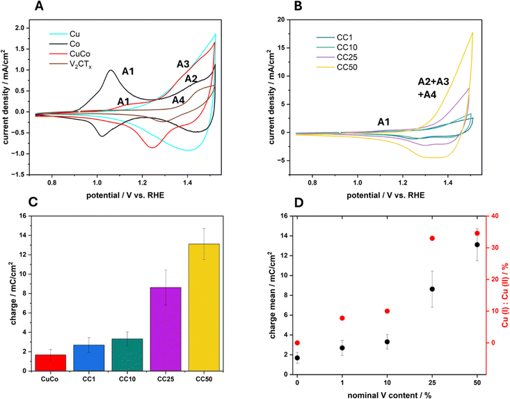
The electrocatalytic activity of the four composite materials with different amounts of V2CTx as well as the pure V2CTx, Cu, Co and CuCo was investigated toward OER. First, cyclic voltammetry was conducted at a scan rate of 40 mV s−1 to investigate the redox transitions of each material (Fig. 6A and B).The pure Co catalyst exhibits an oxidation peak at 1.06 V vs. RHE which can be assigned to the redox transition of Co(II) to Co(III) (A1).2 For the same material, a second oxidation peak can be observed around 1.43 V vs. RHE, indicating the transition of Co(III) to Co(IV) (A2).2 While the pure Cu material exhibits a reversible oxidation peak at around 1.40 V vs. RHE, indicating the transition of Cu(I) to Cu(II) (A3). The pure V2CTx has an oxidation peak at 1.43 V vs. RHE which can be attributed to a V(IV) to V(V) redox transition (A4) according to Pourbaix diagrams.34 For the mixed metal composite CuCo, an oxidation peak at 1.08 V vs. RHE can be attributed to the oxidation of Co(II) to Co(III) (A1), which is slightly shifted to higher potentials and significantly decreases in charge when compared to the pure Co material. The second peak for the mixed CuCo is observed at 1.44 V vs. RHE which may include the simultaneous transition of Co(III) to Co(IV) and Cu(I) to Cu(II) (A2 and A3).
In relation to the CC1-50 materials, Fig. 6B, the anodic peak (A1) for the Co(II) to Co(III) redox transition occurs at similar potentials however, lower current densities (Fig. S9†) compared to the mixed CuCo (Fig. 6A). Interestingly, an increase in the redox capacitance of the grouped A2–A4 peak of about 1.44 V vs. RHE with increasing V2CTx in the sample is observed (Fig. 6C). However, the relative amount of V2CTx in the composite samples is less than in the pure V2CTx hence, the increase in the redox capacitance for the CC materials maybe be due to various phenomena. The first reason may be due to the increase in the vanadium content at the surface of the CC materials, which promotes electron transfer in the Cu and Co redox species due to enhanced conductivity, Fig. 5B.35 The second explanation for the increased redox capacitance could be related to the increased Co species at the surface which could cause the increase in charge due to Co(III) to Co(IV) transition, Fig. 6B. Finally, the third plausible reason for the increased redox charge could be due to the higher amount of Cu(I) species with increasing V2CTx content, Fig. 6D. The peak at 1.44 V vs. RHE, as previously mentioned, can also be assigned to the Cu(I) to Cu(II) redox transition and if more Cu(I) species are present on the surface of a material before this redox transition the resulting redox peak will have a greater charge due to the formation of Cu(II).
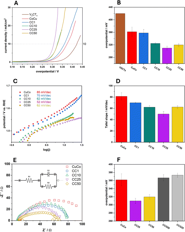
Typical linear sweep voltammograms of the pure and composite catalysts in 1 M NaOH can be observed in Fig. 7A and overpotential values at 10 mA cm−2 (η10) of the average of three independent electrodes with standard deviations for each catalyst are presented in Fig. 7B. The pure V2CTx catalyst exhibits an average overpotential at 10 mA cm−2 of 420 mV while the overpotential at the same current density for the pure CuCo is 360 mV. The chemically functionalized materials all show lower η10 values compared to the pure material, which shows their increased electrocatalytic activity regarding the OER. For the 1%, 10% and 25% CC materials, the η10 values become lower, indicating that subsequent additions of V2CTx to 25% improves the OER. With 50% V2CTx, the OER performance slightly decreases, however the performance is equal to that of the 10% CC material.
The Tafel slope values for the pure and composite materials were also calculated and are presented in Fig. 7C. The same trend for the Tafel slopes values, Fig. 7D, can be observed as in Fig. 7B for the overpotentials at 10 mA cm−2. The Tafel slope value for the pure CuCo materials is 85 mV dec−1 which decreases to 70 mV dec−1 for the CC1, then to 62 mV dec−1 for CC10 and, finally 52 mV dec−1 for the CC25. This decrease in Tafel slope value shows that the chemical functionalization of the V2CTx to the pure CuCo materials allows the OER to proceed at a faster rate than the pure CuCo. For the CC 50 material, the Tafel slope increases to 62 mV dec−1 which indicates the rate of the OER in the measured region is slowing down compared to CC25. This may indicate that there is an optimum amount of V2CTx which is beneficial to the system for improving the OER, especially since the same trend is observed for the overpotential at 10 mA cm−2 in Fig. 5B.
The Nyquist plots in Fig. 7E and Table S1† show the charge transfer characteristics of the pure and composite materials taken at 1.6 V vs. RHE during OER. It is evident that the CC25 and CC50 have similar charge transfer resistances, although the CC50 has a higher double layer capacitance due to significantly higher MXene content. The CC10 and CC1 exhibit roughly the same properties; however, exhibit reduced charge transfer properties compared to the CC25 and CC50. The pure CuCo exhibits the most sluggish charge transfer compared to MXene supported catalysts hence, showing that the V2CTx (MXene) plays a major role in increasing the charge transfer properties of the pure CuCo during the OER.
In order to further validate that the enhanced OER performance of the V2CTx MXene-containing composites is not only due to increased surface area or charge transfer properties, graphene was used as an alternative to the V2CTx in the synthesis process. Two CuCo/graphene-based (CCG) composites were prepared by the same hydrothermal route containing 25 and 50% graphene to compare to the CC25 and CC50 to determine the overpotential at which these two graphene composites reach 10 mA cm−2, Fig. 9. It is evident from Fig. 9 that the graphene composites exhibit similar or higher overpotential values at 10 mA cm−2 when compared to the pure CuCo material and the V2CTx MXene composites clearly outperform their graphene counterpart composites.
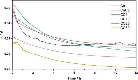
Another important parameter for water splitting applications is the stability of the catalysts under operation for extended periods of time. The stability tests for the pure Co, pure CuCo and CC materials in this study were carried out at a current density of 10 mA cm−2 for 12 hours, Fig. 8.
All the pure and composite material activities at the start of the stability test are improved within the first 1–4 hours when 10 mA cm−2 is applied. The pure Co catalyst starts to slightly decline around 6 hours. Interestingly, for all the materials that contain Cu, the stability is constant after the 6 hour mark, or the activity improves. At 12 hours of operation, the activity of the CC50 shows the best OER activity of ∼285 mV at 10 mA cm−2, which is retained after 24 hours of operation, Fig. S10.† It is evident from the stability tests that the addition of the Cu to the Co stabilizes the CuCo compared to the Co during the stability test while the addition of the V2CTx has a significant effect on the overall activity over prolonged times. The V2CTx is clearly advantageous in the composite as a pre-catalyst as the CC25/50 composites in this study as it out-performs similar materials made from Co, Cu and V in the literature, Table S2.†
3.3. Discussion of improved activity for the MXene composite materials
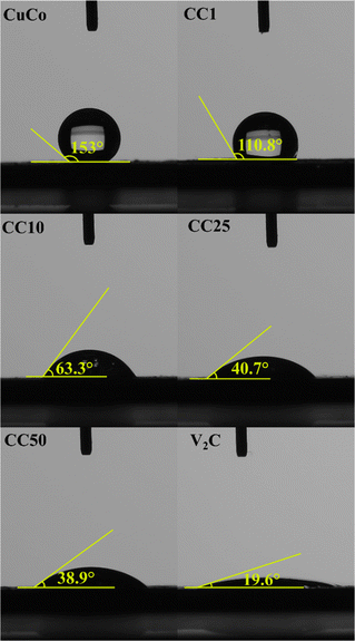
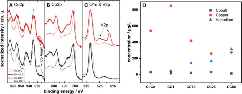
To elucidate the reasoning behind the improvement of the composite catalysts, the effect of the MXene on the hydrophilicity of the surface was investigated alongside post-mortem XPS to gain insight to the oxidation states and ICP-OES to determine dissolution rates of the Co, Cu and V.First, the hydrophilic nature of the pure and composites were determined by contact angle measurements, Fig. 9. This is because hydrophilic materials are advantageous in water splitting applications, such as the OER, due to the increased wettability of the catalyst surface when in contact with the aqueous electrolyte. V2CTx when synthesized by the in situ method, which was used in this study, is known to yield hydrophilic materials in nature due to their OH surface termination sites.36,37
The contact angles of the pure CuCo and composite materials decreased from 153° to 38.9° in proportion to the increasing amount of V2CTx, while the pure V2CTx exhibited the lowest contact angle of 19.6°. The addition of 1% of the V2CTx lowered the contact angle in comparison to the pure CuCo materials, however, it was insufficient to change the hydrophobicity nature of the catalyst surface, as the angles were higher than 90°.38 For additions of 10% or more of V2CTx, the angles were less than 90°, confirming the hydrophilic behavior of the catalyst surface, which show that the MXene has a role in making the composites with 10% V2CTx or more hydrophilic in nature, allowing the catalytic surface better accessibility to the aqueous electrolyte.
Additionally, post-mortem XPS analysis was conducted to investigate any changes in the chemical states of the pure CuCo and the CC50 material (best performing composite due to the lowest η exhibited after 12 hours of stability test, Fig. 8), Fig. 10A–C. The Cu 2p region shows that the Cu oxide in the pure CuCo remains unchanged after the OER while the reduced Cu species in the CC50 has oxidized to Cu(II), Fig. 10A. For both the pure CuCo and the CC50, the Co species is further oxidized after the OER, as evident from Fig. 10B. Interestingly, the vanadium at the surface of the CC50 is no longer detected, Fig. 10C, and the Co/Cu ratio has significantly increased compared to before OER. However, the Co/Cu ratio for the CC50 is lower than that of the pure CuCo which may indicate that copper leaches out of the pure CuCo at a faster rate during the OER. The lower leaching rate of the Cu/higher amount of the Cu on the surface of the CC50 may be influenced by the V2CTx in the pre-catalyst, which itself might be preferentially leached during OER, as there is no V 2p signal after OER from the XPS, Fig. 10C.
To investigate the leaching effect of the Co, Cu and V during the OER, Inductively Coupled Plasma Optical Emission Spectroscopy (ICP-OES) was carried out on the pure CuCo and the composite materials after stability tests, Fig. 10D. From the ICP-OES results, it is clear that for all of the materials, Co leaching from the electrode into the electrolyte is minimum compared to the Cu leaching. However, interestingly, the amount of the V2CTx does have a significant effect on the amount of Cu leached during the OER. For the composite materials, the material with only 1% V2CTx, has the highest amount of Cu leached during the OER, and the Cu leaching decreases with increasing V2CTx. Furthermore, for the CC50, the materials with the highest amount of V2CTx, also exhibits the highest amount of V2CTx leaching. This result confirms that the V2CTx is preferentially leached instead of the Cu postulated from the post XPS analysis. Hence, the increased performance of the CC50 during the stability tests compared to the other composites may be a result of more Cu remaining in the CuCo materials in the case of the CuCo V2CTx composites.
4. Conclusions
A series of CuCo/V2CTx based composites were prepared by a hydrothermal synthesis method with the V2CTx component ranging from 0 to 50%. The pure and composite materials were identified to be hydroxide carbonate materials by XRD. The XRD showed that for the composite materials, the (002) reflection of the V2CTx shifted to show smaller interlayer spacings observed for multi-layered V2CTx, suggesting restacking during synthesis. The STXM measurements confirm that there are no changes in the vanadium oxidation state in the bulk of the materials when comparing the pure V2CTx and the CC50 after synthesis, showing that no bulk oxidation of the V2CTx occurs during the hydrothermal synthesis. However, surface oxidation of the vanadium in the composite materials is observed from the XPS analysis compared to the pure V2CTx. XPS further revealed that the Cu(II) oxidation state was reduced with increasing MXene added to the composite and the Co component compared to the Cu increased at the surface.Extensive OER performance analysis was carried out on the pure and composite samples and the conclusion was that the CC25-50 materials are the most active for the OER in this study. This increase in OER activity may be related to the various changes in CuCo properties due to the V2CTx in the pre-catalyst including the increase in hydrophilicity of the catalyst surface and increase in charge transfer properties. Additionally, the initial increased activity from the LSVs could be attributed to the interplay of the higher at% of the Co and the reduced Cu oxidation state leading to an ideal pre-catalyst structure on the surface as determined by XPS.
The OER activity of the same CuCo materials with graphene were investigated as well and showed that the enhancement is not just due to the high surface area or conductivity of the MXene as the graphene composites were equal to or exhibited decreased activity for the OER when compared to the pure CuCo material. Furthermore, all the CC V2CTx composites became more active for the OER during the stability tests at 10 mA cm−2 which is attributed to the preferential leaching of the V2CTx over the Cu. Hence, overall, this allowed for a higher concentration of the CuCo active site to remain on the electrode surface thus resulting in higher OER performances for the composites with higher V2CTxi.e. the CC50.
Data availability
Some of the data supporting this article have been included as part of the ESI.† Additionally, the raw data files for this study can be made available by contacting the corresponding author.Author contributions
Bastian Schmiedecke: investigation, data curation, writing – original draft, writing – review & editing. Bing Wu: investigation, writing – review & editing. Thorsten Schultz: investigation, writing – review & editing. Aline Alencar Emerenciano: investigation, writing – review & editing. Namrata Sharma: investigation, writing – review & editing. Danielle A. Douglas-Henry: investigation, writing – review & editing. Apostolos Koutsioukis: investigation, writing – review & editing. Mehmet Turan Görüryılmaz: investigation, writing – review & editing. Valeria Nicolosi: supervision, writing – review & editing. Tristan Petit: supervision, writing – review & editing. Norbert Koch: supervision, writing – review & editing. Zdenek Sofer: supervision, writing – review & editing. Michelle P. Browne: writing – original draft, writing – review & editing, data curation, supervision, investigation, funding acquisition, conceptualization.Conflicts of interest
There are no conflicts to declare.Acknowledgements
We gratefully acknowledge the Helmholtz Association's Initiative and Networking Fund (Helmholtz Young Investigator Group VH-NG-1719) for the funding. M. P. B. greatly acknowledges support from the German Federal Ministry of Education and Research in the framework of the project Catlab (03EW0015A/B) and the Deutsche Forschungsgemeinschaft (DFG, German Research Foundation) under Germany's Excellence Strategy – EXC 2008 – 390540038 UniSysCat. VN wishes to acknowledge funding from the European Research Council (CoG 3D2Dprint, GA 681544), Science Foundation Ireland (12/RC/2278_P2 and 16/RC/3872_P2, Frontiers for the Future 20/FFP-A/8950), and HORIZON-RIA 101091572 GREENCAP. Furthermore, VN and AK wish to thank the support of the EIC Pathfinder ThermoDust project (project number 101046835). DDH would like to thank the SFI-funded CRANN Advanced Microscopy Laboratory (AML) for the provision of their facilities for the electron microscopy characterization and analysis. Z. S. was supported by ERC-CZ program (project LL2101) from Ministry of Education Youth and Sports (MEYS) and used large infrastructure from project Advanced Functional Nanorobots (reg. No. CZ.02.1.01/0.0/0.0/15_003/0000444 financed by the EFRR). NS and TP acknowledge funding from the European Research Council (NANOMXM, GA 947852). The authors would like to address particular thanks to R. Schwiddessen, M. Tovar, K. Schwartzburg and M. Wollgotten from the X-Ray and Microscopy and Spectroscopy corelabs of the Helmholtz Zentrum Berlin for providing access to their facility and training on the equipment. The ICP-OES measurements were carried out by the “Solar Fuels Testing Facility” laboratory of the Helmholtz Energy Materials Foundry (HEMF) and we thank Ursula Michalczik for performing these measurements. We also thank Sebastian Wintz and Markus Weigand for their technical support at the MAXYMUS beamline. Open Access funding enabled and organized by Projekt DEAL.References
- M. P. Browne, Z. Sofer and M. Pumera, Energy Environ. Sci., 2019, 12, 41–58 RSC.
- R. L. Doyle, I. J. Godwin, M. P. Brandon and M. E. G. Lyons, Phys. Chem. Chem. Phys., 2013, 15, 13737–13783 RSC.
- D. McAteer, I. J. Godwin, Z. Ling, A. Harvey, L. He, C. S. Boland, V. Vega-Mayoral, B. Szydłowska, A. A. Rovetta, C. Backes, J. B. Boland, X. Chen, M. E. G. Lyons and J. N. Coleman, Adv. Energy Mater., 2018, 8, 1702965 CrossRef.
- I. S. Filimonenkov, C. Bouillet, G. Kéranguéven, P. A. Simonov, G. A. Tsirlina and E. R. Savinova, Electrochim. Acta, 2019, 321, 134657 CrossRef CAS.
- P. Grinberg, B. A. J. Methven, K. Swider and Z. Mester, ACS Omega, 2021, 6, 22717–22725 CrossRef CAS PubMed.
- M. Görlin, J. Ferreira de Araújo, H. Schmies, D. Bernsmeier, S. Dresp, M. Gliech, Z. Jusys, P. Chernev, R. Kraehnert, H. Dau and P. Strasser, J. Am. Chem. Soc., 2017, 139, 2070–2082 CrossRef PubMed.
- H.-S. Oh, H. N. Nong, T. Reier, A. Bergmann, M. Gliech, J. Ferreira de Araújo, E. Willinger, R. Schlögl, D. Teschner and P. Strasser, J. Am. Chem. Soc., 2016, 138, 12552–12563 CrossRef CAS PubMed.
- M. P. Browne, D. Tyndall and V. Nicolosi, Curr. Opin. Electrochem., 2022, 34, 101021 CrossRef CAS.
- B.-M. Jun, S. Kim, J. Heo, C. M. Park, N. Her, M. Jang, Y. Huang, J. Han and Y. Yoon, Nano Res., 2019, 12, 471–487 CrossRef CAS.
- M. Alhabeb, K. Maleski, B. Anasori, P. Lelyukh, L. Clark, S. Sin and Y. Gogotsi, Chem. Mater., 2017, 29, 7633–7644 CrossRef CAS.
- J. He, P. Lyu and P. Nachtigall, J. Mater. Chem. C, 2016, 4, 11143–11149 RSC.
- N. Li and J. Fan, Nanotechnology, 2021, 32, 252001 CrossRef CAS PubMed.
- D. Tyndall, L. Gannon, L. Hughes, J. Carolan, S. Pinilla, S. Jaśkaniec, D. Spurling, O. Ronan, C. McGuinness, N. McEvoy, V. Nicolosi and M. P. Browne, npj 2D Mater. Appl., 2023, 7, 15 CrossRef CAS PubMed.
- M. Benchakar, T. Bilyk, C. Garnero, L. Loupias, C. Morais, J. Pacaud, C. Canaff, P. Chartier, S. Morisset, N. Guignard, V. Mauchamp, S. Célérier and A. Habrioux, Adv. Mater. Interfaces, 2019, 6, 1901328 CrossRef CAS.
- M. Nazari and A. Morsali, J. Mater. Chem. A, 2024, 12, 4826–4834 RSC.
- D. Gogoi, R. S. Karmur, M. R. Das and N. N. Ghosh, J. Mater. Chem. A, 2023, 11, 23867–23880 RSC.
- C. Kaplan, R. M. Restrepo, T. Schultz, K. Li, V. Nicolosi, N. Koch and M. P. Browne, Electrochim. Acta, 2024, 490, 144269 CrossRef CAS.
- L. Loupias, R. Boulé, C. Morais, V. Mauchamp, N. Guignard, J. Rousseau, J. Pacaud, P. Chartier, M. Gaudon, C. Coutanceau, S. Célérier and A. Habrioux, 2D Materials, 2023, 10, 024005 CrossRef.
- X. Zhao, X. Zheng, Q. Lu, Y. Li, F. Xiao, B. Tang, S. Wang, D. Y. W. Yu and A. L. Rogach, EcoMat, 2023, 5, e12293 CrossRef CAS.
- X. Wu and K. Scott, J. Mater. Chem., 2011, 21, 12344–12351 RSC.
- X. Wang, M. Yang, W. Feng, L. Qiao, X. An, Q. Kong, X. Liu, Y. Wang, Y. Liu, T. Li, Z. Xiang, Q. Wang and X. Wu, J. Electroanal. Chem., 2021, 903, 115823 CrossRef CAS.
- S. Ghorbanzadeh, S. A. Hosseini and M. Alishahi, J. Alloys Compd., 2022, 920, 165811 CrossRef CAS.
- K.-H. Kim and Y.-H. Choi, Mater. Res. Express, 2022, 9, 034001 CrossRef CAS.
- M. Wu, B. Wang, Q. Hu, L. Wang and A. Zhou, Materials, 2018, 11, 2112 CrossRef PubMed.
- G. Ying, S. Kota, A. D. Dillon, A. T. Fafarman and M. W. Barsoum, FlatChem, 2018, 8, 25–30 CrossRef CAS.
- Q. Shan, X. Mu, M. Alhabeb, C. E. Shuck, D. Pang, X. Zhao, X.-F. Chu, Y. Wei, F. Du, G. Chen, Y. Gogotsi, Y. Gao and Y. Dall'Agnese, Electrochem. Commun., 2018, 96, 103–107 CrossRef CAS.
- F. H. Fagerli, Z. Wang, T. Grande, H. Kaland, S. M. Selbach, N. P. Wagner and K. Wiik, ACS Omega, 2022, 7, 23790–23799 CrossRef CAS PubMed.
- F. Amargianou, P. Bärmann, H. Shao, P.-L. Taberna, P. Simon, J. Gonzalez-Julian, M. Weigand and T. Petit, Small Methods, 2004, 2400190 Search PubMed.
- L. Wang, D. Liu, W. Lian, Q. Hu, X. Liu and A. Zhou, J. Mater. Res. Technol., 2020, 9, 984–993 CrossRef CAS.
- M. C. Biesinger, L. W. M. Lau, A. R. Gerson and R. S. C. Smart, Appl. Surf. Sci., 2010, 257, 887–898 CrossRef CAS.
- S. Akir, J. Azadmanjiri, N. Antonatos, L. Děkanovský, P. K. Roy, V. Mazánek, R. Lontio Fomekong, J. Regner and Z. Sofer, Nanoscale, 2023, 15, 12648–12659 RSC.
- R. Lontio Fomekong, S. Akir, F. M. Oliveira, J. Luxa, L. Chacko, J. Regner, L. Dekanovsky, E. Vejmelkova and Z. Sofer, J. Power Sources, 2024, 602, 234293 CrossRef CAS.
- M. C. Biesinger, B. P. Payne, A. P. Grosvenor, L. W. M. Lau, A. R. Gerson and R. S. C. Smart, Appl. Surf. Sci., 2011, 257, 2717–2730 CrossRef CAS.
- M. Lee, X. Ding, S. Banerjee, F. Krause, V. Smirnov, O. Astakhov, T. Merdzhanova, B. Klingebiel, T. Kirchartz, F. Finger, U. Rau and S. Haas, Adv. Mater. Technol., 2020, 5, 2000592 CrossRef CAS.
- S. Akir, R. Lontio Fomekong, L. Chacko, L. Děkanovský, V. Mazánek, J. Sturala, D. Koňáková and Z. Sofer, J. Energy Storage, 2024, 85, 110962 CrossRef.
- M. P. Bilibana, Adv. Sens. Energy Mater., 2023, 2, 100080 CrossRef.
- R. Thakur, A. VahidMohammadi, J. Moncada, W. R. Adams, M. Chi, B. Tatarchuk, M. Beidaghi and C. A. Carrero, Nanoscale, 2019, 11, 10716–10726 RSC.
- Z. Zhang, X. Ma, W. Wang, X. Gong, Y. Zhao, Q. Mu, Z. Xue, X. Liu, H. Zheng and W. Xu, J. Mater. Sci., 2022, 57, 13179–13201 CrossRef CAS.
Footnote |
| † Electronic supplementary information (ESI) available. See DOI: https://doi.org/10.1039/d4ta02700k |
| This journal is © The Royal Society of Chemistry 2024 |


