Enhanced moisture sorption through regulated MIL-101(Cr) synthesis and its integration onto heat exchangers†
Mei Gui Vanessa
Wee
 ab,
Amutha
Chinnappan
 *b,
Runxin
Shang
c,
Poh Seng
Lee
c and
Seeram
Ramakrishna
 *ab
*ab
aIntegrative Sciences and Engineering Programme, NUS Graduate School, National University of Singapore, Singapore 119077, Singapore
bDepartment of Mechanical Engineering, College of Design and Engineering, Centre for Nanotechnology and Sustainability, National University of Singapore, Singapore 117576, Singapore. E-mail: mpecam@nus.edu.sg; seeram@nus.edu.sg
cDepartment of Mechanical Engineering, College of Design and Engineering, Cooling Energy Science Technology Laboratory, National University of Singapore, Singapore, 117576, Singapore
First published on 6th December 2023
Abstract
From residences to industries, cooling processes are energy-intensive yet indispensable. Decoupling the sensible and latent heat loads and delegating the latter to desiccant-coated heat exchangers (DCHEs) permits more energy-efficient cooling. However, the commonplace desiccant – silica gel – has limited water sorption capacity. As a crystalline and water-stable metal–organic framework, MIL-101(Cr) (where MIL stands for Materials Institute Lavoisier) is a promising next-generation desiccant. The current challenges lie in scaling up MIL-101(Cr) production and incorporating it into DCHEs. This work demonstrates how tetraethylammonium hydroxide (TEAOH) is not only less toxic for scaled-up additive-based MIL-101(Cr) synthesis but also produces smaller MIL-101(Cr) particles (40–159 nm) with water uptake capacity up to 1.41 g g−1. Subsequently, TEAOH-MIL-101(Cr) was integrated into heat exchangers using polyvinyl alcohol (PVA) to concurrently bind the cuboctahedral particles and enhance heat and mass transfer. In all three adsorption–desorption cycles, the MIL-101(Cr)/PVA-coated heat exchanger had a gravimetric water uptake twice that of the control silica gel-coated heat exchanger. Moreover, the MIL-101(Cr)/PVA-coated heat exchanger can be regenerated at a desorption temperature of less than 50 °C while adsorbing up to 0.91 g g−1 of moisture. Therefore, the MIL-101(Cr)/PVA-coated heat exchanger is feasible for applications in dehumidification and other systems.
Introduction
Space cooling is a ubiquitous need that remains energy-intensive.1 Not only are cooling processes required to ensure the thermal comfort of room occupants, but they are also integral to preserving various equipment and products.2–5 Since 2018, the International Energy Agency (IEA) has highlighted the need for efficient cooling because the energy demand for space cooling was projected to triple by 2050.1 This need has become more pressing because of the ongoing global energy crisis.6 Unfortunately, the mainstay vapour compression refrigeration systems (VCRS) for cooling applications2,7,8 have limited energy efficiencies with coefficients of performance (COPs) between 2.8–3.8.4,9,10 Hence, there is an impetus for developing more sustainable cooling systems.2,11One strategy towards more energy-efficient cooling entails decoupling the latent and sensible heat loads. Solid desiccant-coated devices can remove the latent heat load before the VCRS (or alternative cooling system) focuses on handling the sensible heat load, thus raising the cooling efficiency.7,12 There are at least three categories of solid desiccant-coated devices: stationary beds, desiccant wheels and desiccant-coated heat exchangers (DCHEs).7,10,12 Notably, DCHEs have several advantages over the other two types of solid desiccant-coated devices.7,10,13 The DCHEs are typically air-to-liquid cross-cooled devices whereby cool water removes the adsorptive heat when the desiccant dehumidifies the airstream.2,7,10 Since water conducts heat more effectively than air, dehumidification using DCHEs can be almost isothermal with high moisture removal capacities (MRCs).2,7,14,15 For instance, using DCHEs cause a change in humidity ratio between the inlet and outlet air that can be 2.5 g kg−1 higher than those for stationary beds or desiccant wheels.7 Moreover, the total cooling load is reduced as dehumidified air from the DCHEs is about 1–3 °C cooler than the ambient air whereas the dehumidified air from stationary beds and desiccant wheels is around 5–10 °C warmer than the ambient air.16,17
Generally, DCHEs have numerous applications including heat transformation, energy storage, atmospheric water harvesting and moisture control.18–21 Nonetheless, DCHEs can be improved via desiccant development, heat exchanger design and application-specific optimisation.2 Existing studies have demonstrated how operation parameters such as air velocity, air specific humidity, water temperature and operation time influence the DCHE's performance.10,14,15,22–26 Subsequently, suitable desiccants can be developed based on these working conditions. For example, the novel desiccant should be stable and have S-shaped type V or type IV water sorption isotherms within the target working temperature and relative humidity (RH) range.2,10,15,27–29 Furthermore, the new desiccant should enable efficient heat and mass transfer for fast kinetics and regeneration at lower temperatures.27,28 Currently, silica gel-based desiccants dominate DCHE investigations.9,22–25,30,31 Being abundant and highly stable, silica gel is an economical desiccant.26,32,33 Yet, silica gel is not an ideal desiccant because of its low water uptake capacity and low thermal conductivity which translate to its high heat of adsorption and requirement for high regeneration temperatures.3,26,32,33 Hence, novel desiccants with properties including higher water uptake capacities and lower regeneration temperatures are desirable.10,12,15,27 Novel screening methods, such as the infrared detection method proposed by Wöllner et al., can also accelerate the determination of a desiccant's water sorption isotherm and cyclic stability.20 Next, applying the new desiccant onto the heat exchanger also requires careful consideration: the desiccant coating should have the optimal thickness (for example, 0.1–0.2 mm)9,14,22,23 and uniformity for high desiccant utilisation while mitigating the pressure drop.12,14,27 Hence, studies on new binder selection and novel uniform coating techniques are necessary.12,27,34 For instance, Li et al.'s work has highlighted the five characteristics of ideal binders for such applications.33,35 The heat exchanger's design also influences the DCHE's performance.2,10,14 Besides the commonplace fin-tube heat exchangers, other designs such as the wire-and-tube, microchannel,19 concentric tube, metal foam, plate,23 finless and lattice heat exchangers have been developed.10 Modifying existing designs, such as the size and pitch of a heat exchanger's tubes, can also translate to improved heat and mass transfer.14,15,27 Lastly, the new and improved DCHE should be integrated and evaluated within existing systems.10,12,25
Novel desiccants under investigation include those based on metal–organic frameworks (MOFs). With inorganic metal clusters and organic ligands arranged in specific frameworks, MOFs have large specific surface areas and hence many potential sorption sites for related applications.33 Currently, MOFs are promising next-generation sorbents with the increasingly feasible transition from laboratory- to industrial-scale production.36 Unlike silica gel, MOF-based desiccants offer several advantages: increased water sorption capacities (for example, above 1 g g−1),37,38 increased specific surface areas (for example, above 650 m2 g−1)22 and lower desorption temperatures (for example, below 70 °C).4,32,39 Moreover, specific MOFs such as aluminium fumarate,39–41 MIL-100(Fe)4,40 and MIL-101(Cr),28,40 are stable in air and water and have been explored for water sorption. This work focuses on MIL-101(Cr) (where MIL stands for the Materials Institute Lavoisier) which has one of the highest water uptake capacities among existing water-stable MOFs.33,42 Firstly, the low water ligand exchange rates translate to this Cr(III) carboxylate MOF's water stability.43 MIL-101(Cr)'s hydrophilic chromium oxo-clusters44 and mesoporous cages45,46 are also essential to its high water uptake capacity and type V water sorption isotherm.47 Specifically, mesopores around 2 nm in diameter favour the capillary condensation of water.48 Overall, MIL-101(Cr) has a cubic unit cell belonging to the Fd![[3 with combining macron]](https://www.rsc.org/images/entities/char_0033_0304.gif) m space group and high permanent porosity: specific Brunauer–Emmett–Teller surface area (SBET) = 2300–4230 m2 g−1
m space group and high permanent porosity: specific Brunauer–Emmett–Teller surface area (SBET) = 2300–4230 m2 g−1![[thin space (1/6-em)]](https://www.rsc.org/images/entities/char_2009.gif) 43 and total pore volume (Vpore) = 1.37–2.15 cm3 g−1.49
43 and total pore volume (Vpore) = 1.37–2.15 cm3 g−1.49
Existing studies on MIL-101(Cr)-coated heat exchangers typically rely on numerical models for performance evaluation. Graf et al. reported a prototype heat exchanger consisting of extruded aluminium pipes with fins and desiccant material (less than 250 mg) as packed beds between the fins.28 It was used experimentally to determine the heat transfer and diffusion coefficients that then serve as inputs into a full-scale adsorption chiller model.28 From the model, for adsorption at 20 °C, desorption at 80 °C, condensation at 20 °C and evaporation at 10 °C, MIL-101(Cr) has a COP of 0.57.28 Elsewhere, Han and Chakraborty synthesised MIL-101(Cr), NH2-MIL-101(Cr) and NH3+Cl−-MIL-101(Cr), collected their water sorption isotherms from 30–80 °C at 10 °C intervals and investigated their cyclic stability with adsorption at 30 °C and 90% RH followed by desorption at 70 °C and 10% RH with each adsorption–desorption cycle lasting five minutes.34 Subsequently, these isotherms and kinetics data were used for simulating the adsorption desalination performance of coated finned-tube heat exchangers.34 Under these conditions, MIL-101(Cr) resulted in a COP of about 0.07, increasing to about 0.12 for NH2-MIL-101(Cr) and about 0.9 for NH3+Cl−-MIL-101(Cr).34 This result stems from introducing the amino group and protonating MIL-101(Cr) to raise its hydrophilicity in the low-pressure regions, thus enhancing the higher water transfer per desalination cycle.34 More recently, Pan et al. proposed a model based on the first law of thermodynamics to evaluate the cooling power utilisation efficiency (CPUE) of DCHEs for dehumidification.50 The different desiccants investigated were silica gel, FAM-Z01, FAM-Z02, FAM-Z05, HKUST-1 and MIL-101(Cr).50 The MIL-101(Cr)-coated heat exchanger had the highest CPUE (above 0.95), followed by FAM-Z02 and HKUST-1 in joint second, FAM-Z01 and FAM-Z05 in joint third and lastly the silica gel-coated heat exchanger (CPUE 0.6–0.8).50
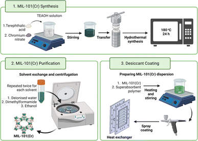
Therefore, MIL-101(Cr)-coated devices have demonstrated promise in several applications, particularly in dehumidification. The current literature also lacks physical experiments on MIL-101(Cr)-coated heat exchangers. Finned-tube heat exchangers are conventionally large devices (400 mm × 400 mm × 88 mm)23 although smaller units (for example, 200 mm × 160 mm × 50 mm) are also available.22,51 As a gauge, the typical finned-tube heat exchanger requires one to two kilograms of silica gel for coating its pipes and fins to a thickness of 0.17 mm![[thin space (1/6-em)]](https://www.rsc.org/images/entities/char_2009.gif) 23 and the smaller units may still need a few hundred grams of silica gel for coating.51 Hence, to realise MIL-101(Cr)-coated heat exchangers, scalable MIL-101(Cr) synthesis and methods of coating MIL-101(Cr) onto heat exchangers are necessary. This work presents a scalable and less toxic additive-based MIL-101(Cr) synthesis (Fig. 1) for controlled particle size and high water uptake capacity. It also highlights the dual use of superabsorbent polymers to absorb moisture and bind the MIL-101(Cr) particles. Finally, MIL-101(Cr)-coated heat exchangers were tested to determine their water sorption performance.
23 and the smaller units may still need a few hundred grams of silica gel for coating.51 Hence, to realise MIL-101(Cr)-coated heat exchangers, scalable MIL-101(Cr) synthesis and methods of coating MIL-101(Cr) onto heat exchangers are necessary. This work presents a scalable and less toxic additive-based MIL-101(Cr) synthesis (Fig. 1) for controlled particle size and high water uptake capacity. It also highlights the dual use of superabsorbent polymers to absorb moisture and bind the MIL-101(Cr) particles. Finally, MIL-101(Cr)-coated heat exchangers were tested to determine their water sorption performance.
Experimental
Synthesis of MIL-101(Cr)
The synthesis procedure was adapted from literature reports.38,52 Following the preparation of the quaternary alkylammonium hydroxide solution, terephthalic acid was added and stirred at room temperature for 10 min. Next, an equimolar amount of chromium(III) nitrate nonahydrate was added before stirring the grey-green suspension for another 20 min at room temperature. The mixture was then transferred to a Teflon-lined autoclave and heated at 180 °C throughout the desired reaction time. After cooling, the suspension obtained was washed successively with deionised water, dimethylformamide and ethanol before being isolated by centrifugation and oven-dried. One-litre autoclaves can produce up to 30 g of TEAOH-MIL-101(Cr) per batch.Preparation of MIL-101(Cr)/binder samples
The synthesised MIL-101(Cr) was first ground before overnight drying in an oven. Next, MIL-101(Cr) dispersions were prepared by adding known masses of dried and ground MIL-101(Cr) to deionised water and sonicating the mixture for 30 min as the temperature increased from 22 to 50 °C. The green MIL-101(Cr) dispersion was then placed on a hot plate (preheated at 100 °C) and stirred whilst adding known masses of the respective binders. After 30 min of heating and stirring, each dispersion was pipetted onto a clean and dry aluminium foil of fixed dimensions and known mass. The samples were air-dried to remove liquid water before being oven-dried. On the other hand, the 2MIL-101(Cr)/1silicate sample was prepared based on previous work by Cui et al.4Coating on prototype heat exchangers
Before applying the desiccant coating, the prototype cross-flow tube bank heat exchangers53 were cleaned sequentially with deionised water, concentrated nitric acid, sodium hydroxide and deionised water again. The heat exchanger was dried overnight in an oven and its dry mass (MHE) was recorded. As described above, MIL-101(Cr) dispersions were prepared (1.9 g of MIL-101(Cr), 0.63 g of PVA and 150 mL of deionised water). The suspension was applied onto the heat exchanger, air-dried and then oven-dried. This process was repeated to reach the targeted mass of desiccant coating (2.2 g).Results and discussion
Scalable and less toxic MIL-101(Cr) synthesis
Obtaining sufficient MIL-101(Cr) for coating onto heat exchangers presents an obstacle to conducting experiments. MIL-101(Cr) is conventionally prepared using Férey et al.'s pioneering approach of heating chromium nitrate nonahydrate (Cr(NO3)3·9H2O), terephthalic acid (H2BDC) and hydrofluoric acid (HF) at 220 °C for eight hours.54 However, HF is highly toxic, thus spurning multiple investigations into other additives and additive-free syntheses to realise the large-scale synthesis of MIL-101(Cr).43 Furthermore, fluoride-free or fully hydroxylated MIL-101(Cr) often have higher water sorption capacities.55 Although additive-free syntheses are inherently less hazardous,43 MIL-101(Cr) prepared through additive-free syntheses may be present as irregularly shaped particles52,56–58 and obtained in low yields (for example, 14% based on Cr).59 Therefore, additive-based MIL-101(Cr) syntheses remain pertinent.60 Nitric acid (HNO3) is currently the leading additive for scaled-up MIL-101(Cr) synthesis because it has provided over 300 g of product61 with yields of around 65–82% based on Cr.56,61–64 However, HNO3 is toxic and a strong oxidiser. It also accelerates metal corrosion in the autoclaves used for hydrothermal syntheses.65 Hence, less hazardous additive-based MIL-101(Cr) syntheses are necessary.By deprotonating terephthalic acid, alkali-based syntheses facilitate coordination between chromium cations and these dicarboxylic acid linkers to yield more MIL-101(Cr).43,52 Alkalis for synthesising MIL-101(Cr) include tetramethylammonium hydroxide (TMAOH) and sodium hydroxide (NaOH).55 Currently, NaOH-based MIL-101(Cr) syntheses still pend optimisation because the resulting MIL-101(Cr) has highly variable SBET from SBET = 1537,66 1767![[thin space (1/6-em)]](https://www.rsc.org/images/entities/char_2009.gif) 67 to 4065 m2 g−1.56 On the other hand, Yang et al. had previously optimised TMAOH-based MIL-101(Cr) synthesis (1Cr(NO3)3
67 to 4065 m2 g−1.56 On the other hand, Yang et al. had previously optimised TMAOH-based MIL-101(Cr) synthesis (1Cr(NO3)3![[thin space (1/6-em)]](https://www.rsc.org/images/entities/char_2009.gif) :
:![[thin space (1/6-em)]](https://www.rsc.org/images/entities/char_2009.gif) 1H2BDC
1H2BDC![[thin space (1/6-em)]](https://www.rsc.org/images/entities/char_2009.gif) :
:![[thin space (1/6-em)]](https://www.rsc.org/images/entities/char_2009.gif) 0.25TMAOH
0.25TMAOH![[thin space (1/6-em)]](https://www.rsc.org/images/entities/char_2009.gif) :
:![[thin space (1/6-em)]](https://www.rsc.org/images/entities/char_2009.gif) 280H2O) whereby lower TMAOH concentrations produce MIL-101(Cr) containing unreacted terephthalic acid and even traces of MIL-53(Cr) whereas higher concentrations yield amorphous solids instead of crystalline MIL-101(Cr).52,68 TMAOH-MIL-101(Cr) has several advantages. Firstly, the hydrothermal reaction proceeds at the lower temperature of 180 °C instead of 200–220 °C for HF-MIL-101(Cr) syntheses.43,52 TMAOH also produces smaller MIL-101(Cr) particles by slowing crystal growth.55,56 For example, Yang et al. and Zhao et al. both reported a narrower particle size distribution for TMAOH-MIL-101(Cr) versus HF-MIL-101(Cr).52,56 Thirdly, TMAOH hinders the recrystallisation of terephthalic acid to enable higher yields (for example, 88% based on Cr).43,52 Moreover, TMAOH-MIL-101(Cr) has water sorption capacities above 1.30 g g−1,69,70 which is the maximum water uptake capacity for HF-MIL-101(Cr).45,46,71
280H2O) whereby lower TMAOH concentrations produce MIL-101(Cr) containing unreacted terephthalic acid and even traces of MIL-53(Cr) whereas higher concentrations yield amorphous solids instead of crystalline MIL-101(Cr).52,68 TMAOH-MIL-101(Cr) has several advantages. Firstly, the hydrothermal reaction proceeds at the lower temperature of 180 °C instead of 200–220 °C for HF-MIL-101(Cr) syntheses.43,52 TMAOH also produces smaller MIL-101(Cr) particles by slowing crystal growth.55,56 For example, Yang et al. and Zhao et al. both reported a narrower particle size distribution for TMAOH-MIL-101(Cr) versus HF-MIL-101(Cr).52,56 Thirdly, TMAOH hinders the recrystallisation of terephthalic acid to enable higher yields (for example, 88% based on Cr).43,52 Moreover, TMAOH-MIL-101(Cr) has water sorption capacities above 1.30 g g−1,69,70 which is the maximum water uptake capacity for HF-MIL-101(Cr).45,46,71
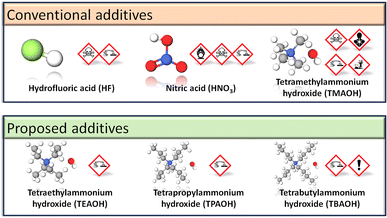
Nonetheless, TMAOH remains inherently toxic (Fig. 2) and further improvements to alkali-based MIL-101(Cr) syntheses are feasible. Longer chain quaternary alkylammonium hydroxides, such as tetraethylammonium hydroxide (TEAOH), tetrapropylammonium hydroxide (TPAOH) and tetrabutylammonium hydroxide (TBAOH), have Globally Harmonised System of Classification and Labelling of Chemicals (GHS) symbols or hazard pictograms (Fig. 2) that indicate their lower toxicity versus TMAOH. Not only are these hydroxides miscible in water,72 but they may also be stronger Lewis bases than TMAOH, thus permitting the reaction to proceed at lower hydroxide concentrations. In practice, basicity does not increase proportionally with the quaternary alkylammonium hydroxide's alkyl chain length. We observed that for the same mass of terephthalic acid in 5% solutions, terephthalic acid was more soluble in TMAOH and TEAOH than TPAOH or TBAOH. Gao et al. also reported that for the same concentration of 0.1 M, TBAOH has a lower degree of ionic dissociation and is a weaker base than TMAOH and TEAOH.72 From their base dissociation constants (pKb), TEAOH is a stronger alkali (pKb = −1.75)73 than TMAOH (pKb = 4.2)74 and TBAOH (pKb = −0.56).75 To our knowledge, there is one report on TEAOH-based MIL-101(Cr) synthesis. However, the low SBET = 1270 m2 g−1 for the milligram scale reaction76 suggests that the reaction conditions have yet to be optimised because MIL-101(Cr) typically has SBET = 2300–3500 m2 g−1.43 Therefore, this work optimises the TEAOH concentration for less hazardous and scalable MIL-101(Cr) synthesis.
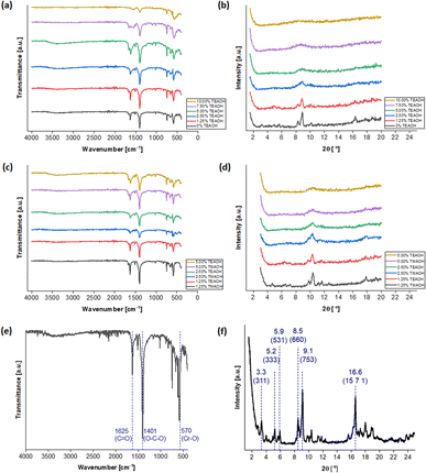
The synthesis procedure was adapted from existing reports38,52 and is detailed in the Experimental section. Five concentrations of TEAOH solution (1.25, 2.50, 5.00, 7.50 and 10.00%) were investigated for MIL-101(Cr) synthesis. As a control experiment of the same scale, a TEAOH-free reaction mixture (0% TEAOH) was also prepared but only yielded a small amount of pale green solid (Fig. S1†). While green solids were isolated from reaction mixtures with 1.25, 2.50 and 5.00% solutions, those containing the 7.50 and 10.00% TEAOH solutions yielded blue solids (Fig. S1†). These solids were screened by attenuated total reflection Fourier-transform infrared spectroscopy (ATR-FTIR) (Fig. 3a) and powder X-ray diffraction (PXRD) (Fig. 3b). As shown in Fig. 3a, instead of a sharp peak corresponding to MIL-101(Cr)'s Cr–O vibration (570 cm−1),77 broad peaks were observed for the samples that appeared as blue solids. Moreover, Fig. 3b indicates that the samples become less crystalline with increasing TEAOH concentrations, particularly with no peaks for the samples from 7.50 and 10.00% TEAOH solutions. This outcome concurs with the dissolution of MIL-101(Cr) into amorphous solids under high TMAOH concentrations.52 Hence, the optimal TEAOH concentration is likely 5.00% or less.
For comparison, samples were also synthesised using 1.25, 2.50 and 5.00% TMAOH solutions. The spectra in Fig. 3c and d demonstrate similarities between samples prepared using TMAOH and TEAOH of the same concentration. Firstly, the ATR-FTIR spectra (Fig. 3c) contain peaks corresponding to MIL-101(Cr)'s C![[double bond, length as m-dash]](https://www.rsc.org/images/entities/char_e001.gif) O (1625 and 1570 cm−1),77,78 O–C–O (1401 cm−1)58,78 and Cr–O (570 cm−1) bonds,58,77 thus demonstrating the successful synthesis of MIL-101(Cr). However, samples prepared using 2.50 and 5.00% solutions exhibited broad peaks with low intensities on the PXRD spectra, pointing to poor crystallinity in these samples (Fig. 3d). On the contrary, the samples synthesised using 1.25% solutions yielded sharper peaks. Furthermore, according to Ko et al.'s protocol for preparing MIL-101(Cr) for proton nuclear magnetic resonance (NMR) measurement,38 the TEAOH-based approach did not modify the terephthalic linker (Fig. S2†). Hence, the optimal TEAOH concentration for MIL-101(Cr) synthesis is 1.25% and slow scans were conducted with the ATR-FTIR peaks and functional groups highlighted in Fig. 3e and the selected PXRD peaks and crystal planes marked in Fig. 3f.54,79
O (1625 and 1570 cm−1),77,78 O–C–O (1401 cm−1)58,78 and Cr–O (570 cm−1) bonds,58,77 thus demonstrating the successful synthesis of MIL-101(Cr). However, samples prepared using 2.50 and 5.00% solutions exhibited broad peaks with low intensities on the PXRD spectra, pointing to poor crystallinity in these samples (Fig. 3d). On the contrary, the samples synthesised using 1.25% solutions yielded sharper peaks. Furthermore, according to Ko et al.'s protocol for preparing MIL-101(Cr) for proton nuclear magnetic resonance (NMR) measurement,38 the TEAOH-based approach did not modify the terephthalic linker (Fig. S2†). Hence, the optimal TEAOH concentration for MIL-101(Cr) synthesis is 1.25% and slow scans were conducted with the ATR-FTIR peaks and functional groups highlighted in Fig. 3e and the selected PXRD peaks and crystal planes marked in Fig. 3f.54,79
The green solids isolated from reaction mixtures containing 1.25% TEAOH solutions were also characterised through Field Emission Scanning Electron Microscopy (FESEM) (Fig. 4) and Transmission Electron Microscopy (TEM) (Fig. 5 and 6b). Cuboctahedral particles were observed through these microscopy techniques, thus having a morphology like MIL-101(Cr) synthesised using TMAOH.52 Notably, these particles were smaller (40–159 nm) than those prepared using 1.25% TMAOH (103–251 nm, Fig. S3a and S4†). Likewise, they were smaller than MIL-101(Cr) synthesised with TMAOH by Yang et al. (200–300 nm)52 and other authors (150–250 nm).80,81
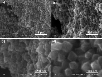 | ||
| Fig. 4 FESEM images of samples prepared using 1.25% TEAOH solutions showing cuboctahedral particles with scale bars at (a) 1 μm, (b) 500 nm, (c) 250 nm and (d) 100 nm. | ||
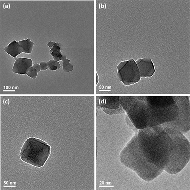 | ||
| Fig. 5 TEM images of samples prepared using 1.25% TEAOH solutions showing cuboctahedral particles with scale bars at (a) 100 nm, (b and c) 50 nm and (d) 20 nm. | ||
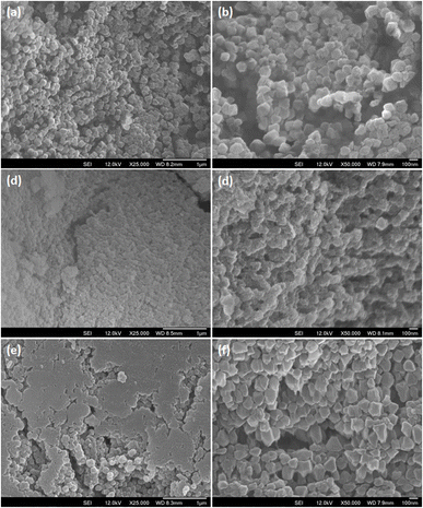
Smaller MIL-101(Cr) particles could enhance the binding between MIL-101(Cr) and the added binder, leading to more continuous coatings. Hence, the additive-based regulation of MIL-101(Cr) particle sizes is also attractive. For example, with monocarboxylic acid additives of higher acid dissociation constants (pKa), smaller MIL-101(Cr) particles can be synthesised.60,82 The proposed mechanism is that when monocarboxylic acids dissociate less readily, the relative concentration of monocarboxylate ions in the solution is lower, selecting for nucleation instead of crystal growth.82 Therefore, a similar form of particle size regulation may be feasible through quaternary alkylammonium hydroxides with different pKb values that deprotonate terephthalic acid by different extents to alter the nucleation and crystal growth rates.
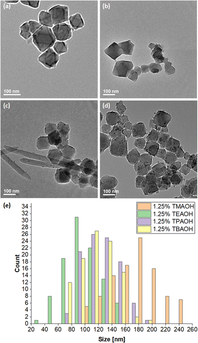
Fig. 6a and b depict the TMAOH- and TEAOH-MIL-101(Cr) samples respectively under TEM. As mentioned above, using a 1.25% TEAOH solution produced smaller MIL-101(Cr) particles (40–159 nm) than the same concentration of TMAOH (103–251 nm) solution. For further investigation, samples were also prepared using 1.25% TPAOH and 1.25% TBAOH solutions. Reminiscent of the sample prepared without additives (0% TEAOH), a small amount of pale green solid was obtained from a reaction of the same scale using 1.25% TPAOH. Moreover, despite undergoing the same purification procedure, its corresponding TEM (Fig. 6c and S5†) and FESEM images (Fig. S3c†) show that needlelike crystals of unreacted terephthalic acid remained in the sample alongside the cuboctahedral particles. Hence, the same concentration of TPAOH appears to be less effective at deprotonating and dissolving terephthalic acid than TMAOH or TEAOH. Correspondingly, the particle size distribution (67–181 nm) is slightly larger than that attained with a 1.25% TEAOH solution. On the other hand, reaction mixtures containing 1.25% TBAOH solution yielded green solids. Fig. 6d (also, Fig. S3d and S6†) indicates that the 1.25% TBAOH solution produced larger and more irregularly shaped particles between 61–193 nm. Fig. 6e compares the particle size distribution across the four samples. TMAOH (pKb = 4.2),74 TPAOH and TBAOH (pKb = −0.56)75 produced larger MIL-101(Cr) particles, likely because these hydroxides dissociate less readily to deprotonate and dissolve terephthalic acid, thus facilitating crystal growth over nucleation. As TEAOH (pKb = −1.75),73 it favours the deprotonation and dissolution of terephthalic acid, hence promoting nucleation over crystal growth to yield smaller MIL-101(Cr) particles.
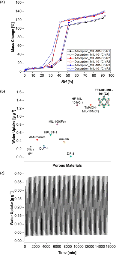
After developing a feasible synthesis approach, TEAOH-MIL-101(Cr)'s water sorption properties were investigated. Firstly, its water sorption isotherms were collected. Consistent with other reports,47 TEAOH-MIL-101(Cr) yielded type V water sorption isotherms. The changes in water sorption capacity with RH also concur with those described elsewhere.46,55,83 Briefly, Fig. 7a shows TEAOH-MIL-101(Cr)'s water isotherms with increasing water sorption capacity from RH = 0–30%. This increase is because water molecules coordinate with MIL-101(Cr)'s open metal sites. Then, the isotherm shows a steep increase in water sorption capacity between RH = 30–50%, which is due to the capillary condensation of water in MIL-101(Cr)'s mesoporous cages. Further increases in water sorption capacity between RH = 50–90% are ascribed to further water uptake in the sample's interparticulate voids.
Initially, TEAOH-MIL-101(Cr) only had a water sorption capacity of 1.22 g g−1 at RH = 90%. TEAOH-MIL-101(Cr)'s pores were probably blocked by unreacted terephthalic acid, solvents and even by-products like chromium oxide.43,84 Hence, the TEAOH-MIL-101(Cr) samples were further purified by washing them in warm ethanol (T = 60 °C) for one hour as per a reported method.69 As illustrated in Fig. 7a, repeatedly washing TEAOH-MIL-101(Cr) with warm ethanol raises its water sorption capacity at RH = 90%. Table 1 summarises how one round of washing (R1) increases the water uptake at RH = 90% to 1.24 g g−1, followed by 1.35 g g−1 after two rounds of washing (R2) and eventually to 1.36 g g−1 after three rounds of washing (R3). This water uptake is higher than that of HF-MIL-101(Cr) and TMAOH-MIL-101(Cr) at 1.28![[thin space (1/6-em)]](https://www.rsc.org/images/entities/char_2009.gif) 37 and 1.29 g g−1
37 and 1.29 g g−1![[thin space (1/6-em)]](https://www.rsc.org/images/entities/char_2009.gif) 38 respectively. It is also greater than those of other MOFs such as aluminium fumarate (Al-fumarate),85 DUT-4,37 HKUST-1,37 MIL-100(Fe),37 UiO-66
38 respectively. It is also greater than those of other MOFs such as aluminium fumarate (Al-fumarate),85 DUT-4,37 HKUST-1,37 MIL-100(Fe),37 UiO-66![[thin space (1/6-em)]](https://www.rsc.org/images/entities/char_2009.gif) 86 and ZIF-8
86 and ZIF-8![[thin space (1/6-em)]](https://www.rsc.org/images/entities/char_2009.gif) 37 (Fig. 7b). Additionally, the highest water uptake capacity recorded in this work is 1.41 g g−1 at RH = 93%.
37 (Fig. 7b). Additionally, the highest water uptake capacity recorded in this work is 1.41 g g−1 at RH = 93%.
| Sample | Water uptake capacity [g g−1] |
|---|---|
| TEAOH-MIL-101(Cr) R1 | 1.24 |
| TEAOH-MIL-101(Cr) R2 | 1.35 |
| TEAOH-MIL-101(Cr) R3 | 1.36 |
TEAOH-MIL-101(Cr) also demonstrated cyclic stability across 100 water vapour adsorption–desorption cycles (Fig. 7c). In this cyclic test, adsorption occurred at T = 25 °C and RH = 50% which is within the step region in MIL-101(Cr)'s isotherm.38,61 For desorption, a milder temperature of T = 50 °C was chosen as existing literature has shown that a similar MOF, MIL-100(Fe), can undergo desorption at this temperature.4 In addition, the adsorption (90 min) and desorption (65 min) durations were adapted from previous work by Entezari et al.87 Under these conditions, TEAOH-MIL-101(Cr) maintained a peak water uptake above 0.35 g g−1. This cyclic stability is important for dehumidification systems whereby the desiccant undergoes repeated adsorption–desorption cycles.
Dual-purpose SAP binder
Silica or silicate sol are common binders for coating MOF-based desiccants onto devices.4,88 Despite being porous and having cyclic stability, these binders still have low water sorption capacities and thermal conductivities,3,32,33 thus hindering the dissipation of adsorptive heat and further water sorption by the desiccant. Better binders that improve the desiccant coating's heat and mass transfer without hindering water sorption are thus desirable.33,35 Using superabsorbent polymers (SAPs) could concurrently bind the MIL-101(Cr) particles while sorbing moisture and enhancing heat and mass transfer. SAPs include commercially available cross-linked polyacrylates and polyacrylamides capable of accommodating water up to 300–400 times their dry mass.21,42 Polyvinyl alcohol (PVA) is also an SAP. With a crystalline melting point of about 230 °C,89 PVA is thermally stable for applications below 200 °C.90 Moreover, PVA forms films readily72 and adheres well to MIL-101(Cr) where Wang et al. used MIL-101(Cr)/PVA cryogels for the solid-phase extraction of drugs from water samples91 and Solovyeva et al. formed MIL-101(Cr)/PVA grains and tablets for adsorbing methanol.92 Hence, this work investigates TEAOH-MIL-101(Cr)/PVA (henceforth, MIL-101(Cr)/PVA) coatings in the adsorption–desorption cycles of water vapour.| Sample | M e [mg g−1] | k [min−1] | R 2 |
|---|---|---|---|
| 1MIL-101(Cr)/1PVA | 301 | 0.01932 | 0.998 |
| 2MIL-101(Cr)/1PVA | 430 | 0.01073 | 0.988 |
| 3MIL-101(Cr)/1PVA | 533 | 0.00903 | 0.991 |
| 3MIL-101(Cr)/1PVA (purified) | 624 | 0.01137 | 0.992 |
| 4MIL-101(Cr)/1PVA | 572 | 0.00781 | 0.989 |
| 5MIL-101(Cr)/1PVA | 587 | 0.00783 | 0.991 |
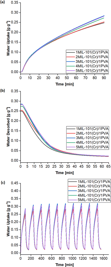
Known to accurately represent MIL-101(Cr)'s water sorption kinetics,93,94 the Linear Driving Force (LDF) mass transfer model was also applied to study the water adsorption rate of these MIL-101(Cr)/PVA coatings. The curve-fitting approach was previously reported by Liu et al. using eqn (1) and (2):
 | (1) |
 | (2) |
 against time t whereby the gradient of the line is −k.93
The LDF model fits the adsorption kinetics well, leading to R2 ≥ 0.988 (Table 2). Generally, increasing the mass ratio of MIL-101(Cr) presents a trade-off between raising the equilibrium uptake (Me) at RH = 50% and lowering the lower adsorption rate constant (k). The 3MIL-101(Cr)/1PVA desiccant balances this trade-off by having a higher Me than the 1MIL-101(Cr)/1PVA and 2MIL-101(Cr)/1PVA desiccants while maintaining higher values of k than its 4MIL-101(Cr)/1PVA and 5MIL-101(Cr)/1PVA counterparts, thus culminating in the highest water uptake after 90 min. Notably, the larger PVA mass ratio in the 1MIL-101(Cr)/1PVA and 2MIL-101(Cr)/1PVA desiccants appears to favour heat and mass transfer within shorter adsorption durations but would adsorb less moisture than the 3MIL-101(Cr)/1PVA desiccant before requiring regeneration. Elsewhere, it has been reported that less frequent switching between a desiccant-coated device's adsorption and regeneration modes can enable a more energy-efficient system.21 Hence, the 3MIL-101(Cr)/1PVA desiccant was chosen for subsequent tests. Subsequently, the 3MIL-101(Cr)/1PVA desiccant was prepared with purified TEAOH-MIL-101(Cr) R3 and underwent the same tests. Both the equilibrium uptake at RH = 50% (Me) and the adsorption rate (k) of the purified 3MIL-101(Cr)/1PVA sample increased from 533 to 624 mg g−1 and from 0.00903 to 0.01137 min−1.
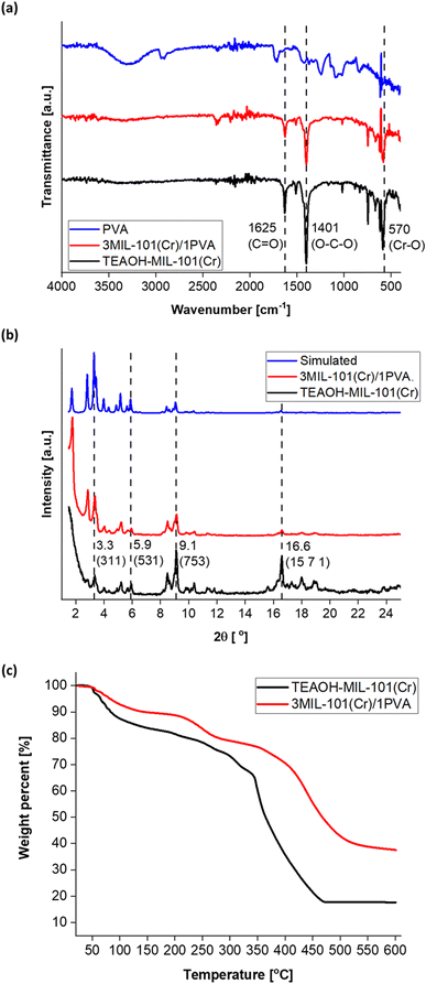
Fig. 9 reflects the characterisation of purified 3MIL-101(Cr)/1PVA via ATR-FTIR, PXRD and thermogravimetric analysis (TGA). Based on ATR-FTIR (Fig. 9a), PVA exhibits peaks at 3289 at 1427 cm−1 because of O–H vibrations, peaks at 2919 and 1245 cm−1 attributed to C–H vibrations, a peak at 1724 cm−1 due to C![[double bond, length as m-dash]](https://www.rsc.org/images/entities/char_e001.gif) O vibration and another peak at 1083 cm−1 from C–O vibration.95 However, 3MIL-101(Cr)/1PVA primarily reflects peaks from the major component – MIL-101(Cr) – in its ATR-FTIR spectrum. Similarly, the 3MIL-101(Cr)/1PVA sample's PXRD spectrum (Fig. 9b) mainly exhibits peaks due to MIL-101(Cr). The TGA data of MIL-101(Cr) and 3MIL-101(Cr)/1PVA are shown in Fig. 9c. MIL-101(Cr) exhibited the first weight loss (16 wt%) between T = 25–150 °C attributed to the removal of guest molecules including water.43,52,69 A plateau-like region (18 wt%) arises between T = 150–343 °C whereby MIL-101(Cr)'s coordinated molecules are removed to produce the solvent-evacuated framework.43 MIL-101(Cr) then has the second weight loss (48 wt%) between T = 343–470 °C where hydroxide ions are removed and the terephthalic acid linker decomposes.43,69 The second plateau region from T = 470–600 °C is due to the formation of chromium oxides.43,52 Similarly, 3MIL-101(Cr)/1PVA exhibited the first weight loss of 10 wt% between T = 25–150 °C – lower than MIL-101(Cr)'s 17 wt%. The weight loss of 3MIL-101(Cr)/1PVA (2 wt%) between T = 150–215 °C is also less than MIL-101(Cr)'s 3 wt% before another 9 wt% decrease from T = 215–300 °C due to the first decomposition step of PVA.89 Therefore, 3MIL-101(Cr)/1PVA remained thermally stable up to 215 °C.
O vibration and another peak at 1083 cm−1 from C–O vibration.95 However, 3MIL-101(Cr)/1PVA primarily reflects peaks from the major component – MIL-101(Cr) – in its ATR-FTIR spectrum. Similarly, the 3MIL-101(Cr)/1PVA sample's PXRD spectrum (Fig. 9b) mainly exhibits peaks due to MIL-101(Cr). The TGA data of MIL-101(Cr) and 3MIL-101(Cr)/1PVA are shown in Fig. 9c. MIL-101(Cr) exhibited the first weight loss (16 wt%) between T = 25–150 °C attributed to the removal of guest molecules including water.43,52,69 A plateau-like region (18 wt%) arises between T = 150–343 °C whereby MIL-101(Cr)'s coordinated molecules are removed to produce the solvent-evacuated framework.43 MIL-101(Cr) then has the second weight loss (48 wt%) between T = 343–470 °C where hydroxide ions are removed and the terephthalic acid linker decomposes.43,69 The second plateau region from T = 470–600 °C is due to the formation of chromium oxides.43,52 Similarly, 3MIL-101(Cr)/1PVA exhibited the first weight loss of 10 wt% between T = 25–150 °C – lower than MIL-101(Cr)'s 17 wt%. The weight loss of 3MIL-101(Cr)/1PVA (2 wt%) between T = 150–215 °C is also less than MIL-101(Cr)'s 3 wt% before another 9 wt% decrease from T = 215–300 °C due to the first decomposition step of PVA.89 Therefore, 3MIL-101(Cr)/1PVA remained thermally stable up to 215 °C.
To quantify MIL-101(Cr) and 3MIL-101(Cr)/1PVA's porosities, their nitrogen (N2) sorption isotherms and pore size distributions (PSD) were analysed. As shown in Fig. 10a, both MIL-101(Cr) and 3MIL-101(Cr)/1PVA have type I N2 sorption isotherms.38,43,62 Both isotherms have two secondary uptakes because of micropore filling43 between the relative pressure (P/P0) of 0.1–0.2 although the corresponding triangular hysteresis loops are more distinct for MIL-101(Cr) than 3MIL-101(Cr)/1PVA. On the other hand, the increased adsorption at P/P0 = 0.9 may stem from the macropores generated during particle aggregation.38 The TEAOH-MIL-101(Cr) sample has SBET = 2714 m2 g−1 and Vpore = 1.68 cm3 g−1 which are within the range of expected values for MIL-101(Cr)43,49 and greater than SBET = 1270 m2 g−1 and Vpore = 1.56 cm3 g−1 reported elsewhere.76 Although 3MIL-101(Cr)/1PVA has a lower SBET (1551 m2 g−1) and Vpore (0.94 cm3 g−1) than TEAOH-MIL-101(Cr), it is more porous than the MIL-101(Cr)/PVA cryogel reported by Wang et al.91 (Table 3). Fig. 10b shows the two samples' PSD. Specifically, TEAOH-MIL-101(Cr) mostly has pores 2.2, 2.8 and 2.9 nm wide and 3MIL-101(Cr)/1PVA has the bulk of its pores at 2.2 and 2.6 nm wide. These values are close to the expected mesopore diameters of 2.9 and 3.4 nm for MIL-101(Cr).46
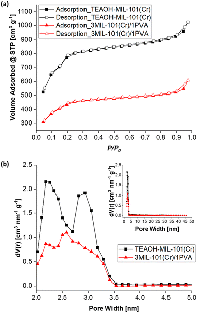 | ||
| Fig. 10 (a) The nitrogen adsorption–desorption isotherms (T = 77 K) and (b) pore size distribution plots of TEAOH-MIL-101(Cr) and 3MIL-101(Cr)/1PVA. | ||
Fig. 11 presents the water sorption isotherms (T = 25 °C) of MIL-101(Cr), 3MIL-101(Cr)/1PVA and the silica gel control. While its water sorption capacity at RH = 90% is approximately thrice that of the silica gel control (0.74 g g−1vs. 0.26 g g−1), 3MIL-101(Cr)/1PVA has a lower water sorption capacity than TEAOH-MIL-101(Cr) itself (1.36 g g−1). As the maximum RH at which the isotherms were collected was 93%, these parameters avoided the condensation of liquid water. Hence, the isotherm portrays the 3MIL-101(Cr)/1PVA coating's ability to adsorb water vapour but not its propensity to absorb liquid water. Similarly, Sapalidis et al. reported that the water sorption isotherm of PVA reaches about 0.3 g g−1 at RH = 90%.90 The difference between adsorption and absorption may also account for the difference in maximum water uptake over 90 min between 3MIL-101(Cr)/1PVA and TEAOH-MIL-101(Cr).
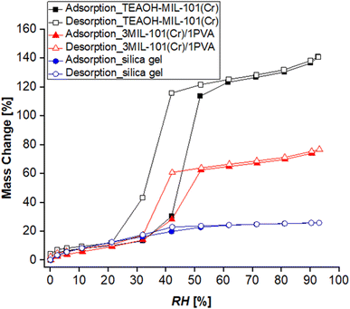 | ||
| Fig. 11 Water adsorption–desorption isotherms (T = 25 °C) of TEAOH-MIL-101(Cr), 3MIL-101(Cr)/1PVA and the silica gel control. | ||
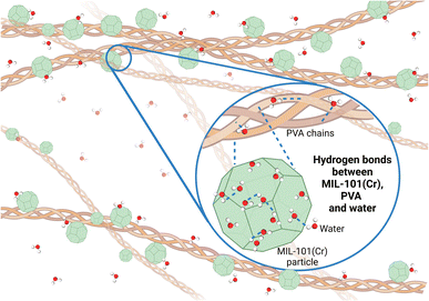
While the 3MIL-101(Cr)/1PVA coating is a physical mixture of MIL-101(Cr) and PVA, there may also be intermolecular interactions between MIL-101(Cr) and PVA. For instance, Dai et al. modelled several interactions between MIL-101(Cr) and sulfonamides including van der Waals' forces, coordination bonds at MIL-101(Cr)'s open-metal sites and intermolecular hydrogen bonds via the oxygen atoms in MIL-101(Cr)'s terephthalic acid linker.96 As water molecules coordinate preferentially to MIL-101(Cr)'s chromium sites,46,83 its carboxylate oxygen atoms are likely available for intermolecular hydrogen bonding with PVA's abundant hydroxyl groups. Hence, PVA not only forms hydrogen bonds with water molecules but also forms hydrogen bonds with MIL-101(Cr) (Fig. 12) in the moisture-sorbing MIL-101(Cr)/PVA coating.
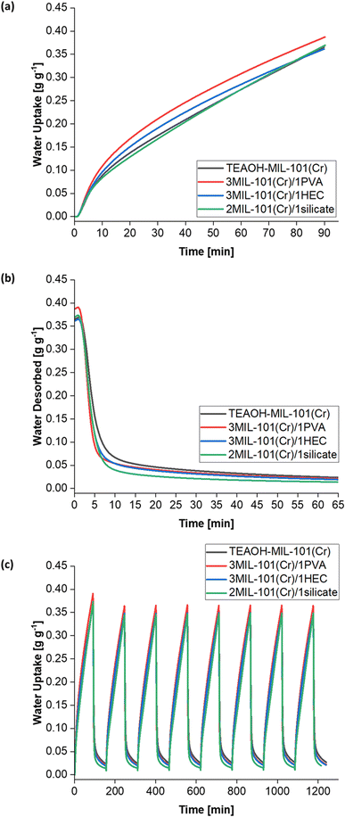
The water sorption kinetics of these samples were investigated. The samples demonstrated cyclic stability over eight cycles (Fig. 14c) and were not saturated after the first 90 min of adsorption at T = 25 °C and RH = 50% (Fig. 14a), thus concurring with the Me > 600 mg g−1 for each sample (Table 4). The 3MIL-101(Cr)/1PVA coating had the highest water uptake 0.36–0.39 g g−1 over 90 min, followed by TEAOH-MIL-101(Cr) at 0.35–0.37 g g−1, 2MIL-101(Cr)/1silicate at 0.34–0.37 g g−1 and 3MIL-101(Cr)/1HEC 0.34–0.36 g g−1. Under these conditions, PVA was the most effective binder for enhancing mass transfer. Fig. 14b shows that during desorption, 3MIL-101(Cr)/1PVA exhibits the greatest extent of regeneration within the first five minutes although 2MIL-101(Cr)/1silicate is regenerated more thoroughly over the whole 65 min at T = 50 °C and RH = 0%.
| Sample | M e [mg g−1] | k [min−1] | R 2 |
|---|---|---|---|
| TEAOH-MIL-101(Cr) | 1136 | 0.00461 | 0.991 |
| 3MIL-101(Cr)/1PVA | 624 | 0.01137 | 0.992 |
| 3MIL-101(Cr)/1HEC | 854 | 0.00672 | 0.988 |
| 2MIL-101(Cr)/1silicate | 686 | 0.00861 | 0.998 |
The adsorption kinetics of the MIL-101(Cr)-based coatings are well-represented by the LDF model whereby R2 ≥ 0.988 (Table 4). As shown in Table 4, the binders improved heat and mass transfer when added to TEAOH-MIL-101(Cr), thus raising the k values. The 3MIL-101(Cr)/1PVA had the highest adsorption rate constant (k = 0.01137 min−1) followed by 2MIL-101(Cr)/1silicate (k = 0.00861 min−1) and 3MIL-101(Cr)/1HEC (k = 0.00672 min−1).
Static gravimetric tests on prototype heat exchanger
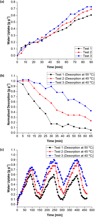
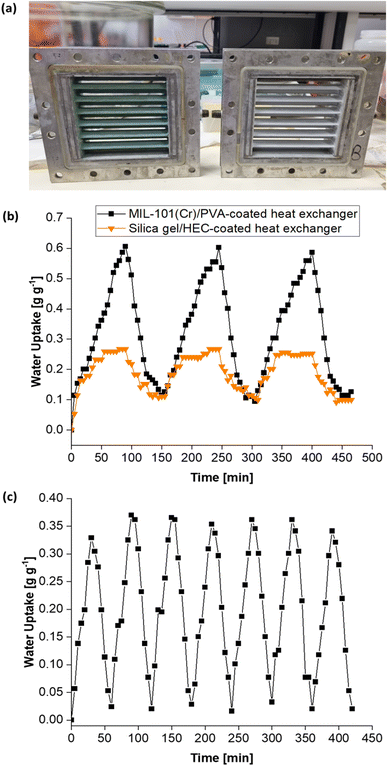
The heat exchanger's design has been described elsewhere.53 In this work, the prototype DCHE were tested based on the mass of water vapour adsorbed under static room conditions (Table 5). Elsewhere, Panigrahi et al. also monitored the mass change of their desiccant-coated samples under static conditions at 5 minute intervals.39 The clean heat exchanger's dry mass (MHE) was recorded before applying any desiccant coatings. After being coated and dried overnight at 100 °C, each DCHE was weighed (MiDCHE). During the adsorption half-cycle, the DCHE's mass was measured from 0–90 min to monitor the moisture sorption at each 5 minute time interval (MnDCHE,ads). At the end of 90 min, moisture was desorbed from the DCHE by placing it in an oven as described in Entezari et al.'s work.87 The DCHE's mass was recorded from 0–65 min to study the moisture desorbed at each time 5 minute interval (MnDCHE,ads). Each DCHE was investigated over three adsorption–desorption cycles whereby eqn (3) determines the water uptake during adsorption and eqn (4) yields the water released during desorption. | (3) |
 | (4) |
| Test no. | Desiccant | Adsorption conditions | Desorption conditions | No. of cycles |
|---|---|---|---|---|
| 1 | 3MIL-101(Cr)/1PVA | 24.3–24.8 °C, 58–64% RH, 90 min | 50 °C (oven), 65 min | 3 |
| 2 | 3MIL-101(Cr)/1PVA | 24.0–24.9 °C, 58–64% RH, 90 min | 45 °C (oven), 65 min | 3 |
| 3 | 3MIL-101(Cr)/1PVA | 24.2–24.7 °C, 58–66% RH, 90 min | 40 °C (oven), 65 min | 3 |
| 4 | 3silica gel/1HEC | 24.1–25.0 °C, 57–65% RH, 90 min | 50 °C (oven), 65 min | 3 |
| 5 | 3MIL-101(Cr)/1PVA | 21.2–21.9 °C, 70–73% RH, 30 min | 50 °C (oven), 30 min | 7 |
Moreover, Fig. 15c (and Table S1†) shows the MIL-101(Cr)/PVA-coated heat exchanger's performance over three adsorption–desorption cycles. Interestingly, partial regeneration after desorption at 40 or 45 °C did not hinder further water sorption. Specifically, the water uptake in the second and third adsorption half-cycles for test 2 increased to 0.78 and 0.83 g g−1 respectively after desorption at 45 °C. Likewise, following desorption at 40 °C, the DCHE in test 3 adsorbed 0.91 g g−1 of moisture during both the second and third adsorption half-cycles. Hence, partially regenerating the MIL-101(Cr)/PVA-coated heat exchanger at lower desorption temperatures of 40 or 45 °C is feasible for reducing energy consumption whilst adsorbing up to 0.91 g g−1 of moisture.
Conclusions
MIL-101(Cr) has water sorption properties superior to silica gel and is well-positioned as a next-generation desiccant. Nonetheless, realising its real-world applications requires improving the scalability of MIL-101(Cr) synthesis and developing methods to integrate it into various devices and systems. Herein, quaternary alkylammonium hydroxides – TEAOH, TPAOH and TBAOH – were explored as alternatives to the more toxic HF- and TMAOH-based MIL-101(Cr) syntheses. Specifically, TEAOH-based MIL-101(Cr) synthesis has been optimised to yield MIL-101(Cr) particles of regulated sizes (40–159 nm) and a high water uptake capacity of up to 1.41 g g−1. This work also demonstrates using PVA to simultaneously bind MIL-101(Cr) particles, enhance heat and mass transfer and absorb moisture. Moreover, based on the LDF model, the 3MIL-101(Cr)/1PVA desiccant yielded an adsorption rate constant more than twice that of MIL-101(Cr) and higher than the other MIL-101(Cr) samples containing the conventional HEC and silicate binders. Besides the material-level tests conducted in water sorption analysers, the 3MIL-101(Cr)/1PVA desiccant was also coated onto prototype heat exchangers for device-level testing. Throughout the three adsorption–desorption cycles, the MIL-101(Cr)/PVA-coated heat exchanger maintained a water uptake double that of the control silica gel-coated heat exchanger. Furthermore, the results showed that regenerating the MIL-101(Cr)/PVA-coated heat exchanger at desorption temperatures of 40 or 45 °C still enables the device to adsorb up to 0.91 g g−1 of moisture. In a preliminary study, the MIL-101(Cr)/PVA-coated heat exchanger demonstrated cyclic stability over seven static adsorption–desorption cycles. Hence, additional optimisation of the MIL-101(Cr)/PVA-coated heat exchanger would eventually culminate in its applications in dehumidification and other heat transformation systems.Author contributions
S. R. and A. C. supervised the project and M. G. V. W. wrote the main manuscript. A. C. and M. G. V. W. contributed to the synthesis and characterisation of samples, measurements and data analysis. P. S. L. and R. S. designed the prototype heat exchanger.Conflicts of interest
The authors declare that a patent has been filed by the National University of Singapore based on this work (SG Patent application no. 10202300869T).Acknowledgements
The authors would like to acknowledge the support given by the National Research Foundation Singapore (Sustainable Tropical Data Centre Testbed: A-0009465-05-00). The authors are grateful to Prof K. J. Chua (Department of Mechanical Engineering, National University of Singapore) and Prof Zhao Dan (Department of Chemical and Biomolecular Engineering, National University of Singapore) for access to the gravimetric water sorption analyser and X-ray powder diffractometer. M. G. V. W. would also like to acknowledge the support given by the NUS Integrative Sciences and Engineering Program (ISEP) scholarship during the period of study.Notes and references
- International Energy Agency, The Future of Cooling, https://www.iea.org/reports/the-future-of-cooling, accessed 27 May 2023 Search PubMed.
- Y. H. Feng, Y. J. Dai, R. Z. Wang and T. S. Ge, Appl. Energy, 2022, 311, 118732, DOI:10.1016/j.apenergy.2022.118732.
- Y. Yang, G. Cui and C. Q. Lan, Renewable Sustainable Energy Rev., 2019, 113, 109230, DOI:10.1016/j.rser.2019.06.037.
- S. Cui, M. Qin, A. Marandi, V. Steggles, S. Wang, X. Feng, F. Nouar and C. Serre, Sci. Rep., 2018, 8, 2–10, DOI:10.1038/s41598-018-33704-4.
- K. Zu and M. Qin, Energy, 2022, 259, 125073, DOI:10.1016/j.energy.2022.125073.
- International Energy Agency, Global Energy Crisis, https://www.iea.org/topics/global-energy-crisis, accessed 14 December 2022 Search PubMed.
- V. Prabakaran and K. J. Chua, in Advances in Desiccant Dehumidification: from Fundamentals to Applications, Springer Nature Switzerland, Singapore, 1st edn, 2021, pp. 1–22 Search PubMed.
- S. Kulkarni, S. Chavali and S. Dikshit, Mater. Today: Proc., 2023, 72, 878–883, DOI:10.1016/j.matpr.2022.09.085.
- Y. D. Tu, R. Z. Wang, T. S. Ge and X. Zheng, Sci. Rep., 2017, 7, 1–10, DOI:10.1038/srep40437.
- T. Venegas, M. Qu, K. Nawaz and L. Wang, Renewable Sustainable Energy Rev., 2021, 151, 111531, DOI:10.1016/j.rser.2021.111531.
- P. Poredoš, H. Shan and R. Wang, Joule, 2022, 6, 1390–1393, DOI:10.1016/j.joule.2022.06.020.
- M. M. Abd-Elhady, M. S. Salem, A. M. Hamed and I. I. El-Sharkawy, Int. J. Refrig., 2022, 133, 337–352, DOI:10.1016/j.ijrefrig.2021.09.028.
- L. Ge, T. Ge and R. Wang, Renewable Sustainable Energy Rev., 2022, 157, 112015, DOI:10.1016/j.rser.2021.112015.
- M. Jagirdar and P. S. Lee, Appl. Energy, 2018, 212, 401–415, DOI:10.1016/j.apenergy.2017.12.038.
- J. A. Shamim, W. L. Hsu, S. Paul, L. Yu and H. Daiguji, Renewable Sustainable Energy Rev., 2021, 137, 110456, DOI:10.1016/j.rser.2020.110456.
- Z. Li, S. Michiyuki and F. Takeshi, Int. J. Heat Mass Transfer, 2015, 89, 641–651, DOI:10.1016/j.ijheatmasstransfer.2015.05.095.
- V. Prabakaran, D. T. Bui, Y. Wong, M. Kumja and K. J. Chua, Appl. Energy, 2019, 237, 733–750, DOI:10.1016/j.apenergy.2019.01.018.
- V. Prabakaran and K. J. E. Chua, in Advances in Desiccant Dehumidification: from Fundamentals to Applications, Springer Nature Switzerland, Singapore, 1st edn, 2021, pp. 127–152 Search PubMed.
- C. Wang, X. Ji, B. Yang, R. Zhang and D. Yang, Appl. Therm. Eng., 2021, 192, 116913, DOI:10.1016/j.applthermaleng.2021.116913.
- M. Wöllner, N. Klein and S. Kaskel, Microporous Mesoporous Mater., 2019, 278, 206–211, DOI:10.1016/j.micromeso.2018.11.024.
- B. Panigrahi, Y. S. Chen, W. J. Luo and H. W. Wang, Sustainability, 2020, 12, 1–16, DOI:10.3390/su12229673.
- S. J. Oh, K. C. Ng, W. Chun and K. J. E. Chua, Energy, 2017, 137, 441–448, DOI:10.1016/j.energy.2017.02.169.
- X. Y. Sun, J. L. Chen, Y. Zhao, X. Li, T. S. Ge, C. H. Wang and Y. J. Dai, Appl. Therm. Eng., 2021, 185, 116342, DOI:10.1016/j.applthermaleng.2020.116342.
- T. S. Ge, J. Y. Zhang, Y. J. Dai and R. Z. Wang, Energy, 2017, 141, 149–158, DOI:10.1016/j.energy.2017.09.090.
- P. Chu, Q. Hu, J. Chen, C. Y. A. Loh, A. Lin, X. Li, D. Chen, K. Leong, Y. Dai and C. H. Wang, Energy Convers. Manage., 2022, 258, 115505, DOI:10.1016/j.enconman.2022.115505.
- C. C. Chang, W. J. Luo, C. W. Lu, Y. S. Cheng, B. Y. Tsai and Z. H. Lin, Science and Technology for the Built Environment, 2017, 23, 81–90, DOI:10.1080/23744731.2016.1210971.
- P. Vivekh, M. Kumja, D. T. Bui and K. J. Chua, Appl. Energy, 2018, 229, 778–803, DOI:10.1016/j.apenergy.2018.08.041.
- S. Graf, F. Redder, U. Bau, M. de Lange, F. Kapteijn and A. Bardow, Energy Technol., 2020, 8, 1900617, DOI:10.1002/ente.201900617.
- Y. D. Tu, R. Z. Wang, L. J. Hua, T. S. Ge and B. Y. Cao, Int. J. Heat Mass Transfer, 2017, 113, 22–31, DOI:10.1016/j.ijheatmasstransfer.2017.05.047.
- S. Nain, A. Parinam and S. Kajal, Mater Today Proc, 2019, 46, 9938–9943 CrossRef.
- S. I. Na, M. Kim and M. S. Kim, Appl. Therm. Eng., 2022, 213, 118723, DOI:10.1016/j.applthermaleng.2022.118723.
- V. Prabakaran and K. J. E. Chua, in Advances in Desiccant Dehumidification: from Fundamentals to Applications, Springer Nature Switzerland, Singapore, 1st edn, 2021, pp. 23–48 Search PubMed.
- A. Karmakar, V. Prabakaran, D. Zhao and K. J. Chua, Appl. Energy, 2020, 269, 115070, DOI:10.1016/j.apenergy.2020.115070.
- B. Han and A. Chakraborty, Desalination, 2022, 541, 116045, DOI:10.1016/j.desal.2022.116045.
- A. Li, K. Thu, A. Bin Ismail, M. W. Shahzad and K. C. Ng, Int. J. Heat Mass Transfer, 2016, 92, 149–157, DOI:10.1016/j.ijheatmasstransfer.2015.08.097.
- A. D. G. Firmino, R. F. Mendes, J. P. C. Tomé and F. A. Almeida Paz, in Metal-Organic Frameworks: Applications in Separations and Catalysis, ed. H. García and S. Navalón, Wiley-VCH Verlag GmbH & Co. KGaA, 1st edn, 2018, pp. 57–80 Search PubMed.
- P. Küsgens, M. Rose, I. Senkovska, H. Fröde, A. Henschel, S. Siegle and S. Kaskel, Microporous Mesoporous Mater., 2009, 120, 325–330, DOI:10.1016/j.micromeso.2008.11.020.
- N. Ko, P. G. Choi, J. Hong, M. Yeo, S. Sung, K. E. Cordova, H. J. Park, J. K. Yang and J. Kim, J. Mater. Chem. A, 2015, 3, 2057–2064, 10.1039/c4ta04907a.
- B. Panigrahi, H. W. Wang, W. J. Luo, Y. C. Chou and J. J. Chen, Science and Technology for the Built Environment, 2023, 29, 323–338, DOI:10.1080/23744731.2023.2170682.
- A. N. Aziz, S. Mahmoud, R. Al-Dadah, M. A. Ismail and M. K. Al Mesfer, Appl. Therm. Eng., 2022, 215, 118940, DOI:10.1016/j.applthermaleng.2022.118940.
- H. Kummer, F. Jeremias, A. Warlo, G. Füldner, D. Fröhlich, C. Janiak, R. Gläser and S. K. Henninger, Ind. Eng. Chem. Res., 2017, 56, 8393–8398, DOI:10.1021/acs.iecr.7b00106.
- V. Prabakaran and K. J. E. Chua, in Advances in Desiccant Dehumidification: from Fundamentals to Applications, Springer Nature Switzerland, Singapore, 1st edn, 2021, pp. 49–88 Search PubMed.
- M. Y. Zorainy, M. Gar Alalm, S. Kaliaguine and D. C. Boffito, J. Mater. Chem. A, 2021, 9, 22159–22217, 10.1039/d1ta06238g.
- J. Zhang, L. Sun, C. Chen, M. Liu, W. Dong, W. Guo and S. Ruan, J. Alloys Compd., 2017, 695, 520–525, DOI:10.1016/j.jallcom.2016.11.129.
- J. Wang, Y. Muhammad, Z. Gao, S. Jalil Shah, S. Nie, L. Kuang, Z. Zhao, Z. Qiao and Z. Zhao, Chem. Eng. J., 2021, 404, 126562, DOI:10.1016/j.cej.2020.126562.
- J. Gao, S. Fei, Y. L. Ho, R. Matsuda, H. Daiguji and J. J. Delaunay, J. Phys. Chem. C, 2021, 125, 17786–17795, DOI:10.1021/acs.jpcc.1c03351.
- M. Wickenheisser, A. Herbst, R. Tannert, B. Milow and C. Janiak, Microporous Mesoporous Mater., 2015, 215, 143–153, DOI:10.1016/j.micromeso.2015.05.017.
- R. Aliakbari, S. Ramakrishna, E. Kowsari, Y. Marfavi, Z. A. Cheshmeh, F. B. Ajdari, Z. Kiaei, H. Torkzaban and M. Ershadi, Res. Chem. Intermed., 2022, 48, 2767–2819, DOI:10.1007/s11164-022-04738-1.
- T. K. Trung, N. A. Ramsahye, P. Trens, N. Tanchoux, C. Serre, F. Fajula and G. Férey, Microporous Mesoporous Mater., 2010, 134, 134–140, DOI:10.1016/j.micromeso.2010.05.018.
- Q. W. Pan, J. Xu, R. Z. Wang and T. S. Ge, Appl. Therm. Eng., 2023, 222, 119943, DOI:10.1016/j.applthermaleng.2022.119943.
- T. S. Ge, Y. J. Dai, R. Z. Wang and Z. Z. Peng, Energy, 2010, 35, 2893–2900, DOI:10.1016/j.energy.2010.03.020.
- J. Yang, Q. Zhao, J. Li and J. Dong, Microporous Mesoporous Mater., 2010, 130, 174–179, DOI:10.1016/j.micromeso.2009.11.001.
- R. Shang, PhD thesis, National University of Singapore, 2021, https://scholarbank.nus.edu.sg/handle/10635/214494.
- C. Férey, C. Mellot-Draznieks, C. Serre, F. Millange, J. Dutour, S. Surblé and I. Margiolaki, Science, 2005, 309, 2040–2042 CrossRef PubMed.
- M. G. V. Wee, A. Chinnappan and S. Ramakrishna, Adv. Mater. Interfaces, 2023, 10, 2300065 CrossRef CAS.
- T. Zhao, S. H. Li, L. Shen, Y. Wang and X. Y. Yang, Inorg. Chem. Commun., 2018, 96, 47–51, DOI:10.1016/j.inoche.2018.07.036.
- L. Yang, T. Zhao, I. Boldog, C. Janiak, X. Y. Yang, Q. Li, Y. J. Zhou, Y. Xia, D. W. Lai and Y. J. Liu, Dalton Trans., 2019, 48, 989–996, 10.1039/c8dt04186e.
- M. Shafiei, M. S. Alivand, A. Rashidi, A. Samimi and D. Mohebbi-Kalhori, Chem. Eng. J., 2018, 341, 164–174, DOI:10.1016/j.cej.2018.02.027.
- R. A. Yang and M. L. Sarazen, Catal. Sci. Technol., 2021, 11, 5282–5296, 10.1039/d1cy00567g.
- P. B. S. Rallapalli, M. C. Raj, S. Senthilkumar, R. S. Somani and H. C. Bajaj, Environ. Prog. Sustainable Energy, 2016, 35, 461–468, DOI:10.1002/ep.12239.
- M. Askarieh, H. Farshidi, A. Rashidi, A. Pourreza and M. S. Alivand, Sep. Purif. Technol., 2022, 291, 120830, DOI:10.1016/j.seppur.2022.120830.
- T. Zhao, F. Jeremias, I. Boldog, B. Nguyen, S. K. Henninger and C. Janiak, Dalton Trans., 2015, 44, 16791–16801, 10.1039/c5dt02625c.
- N. Tannert, Y. Sun, E. Hastürk, S. Nießing and C. Janiak, Z. Anorg. Allg. Chem., 2021, 647, 1124–1130, DOI:10.1002/zaac.202100023.
- M. Sheikh Alivand, N. H. M. Hossein Tehrani, M. Shafiei-Alavijeh, A. Rashidi, M. Kooti, A. Pourreza and S. Fakhraie, J. Environ. Chem. Eng., 2019, 7, 102946, DOI:10.1016/j.jece.2019.102946.
- T. Zhao, L. Yang, P. Feng, I. Gruber, C. Janiak and Y. Liu, Inorg. Chim. Acta, 2018, 471, 440–445, DOI:10.1016/j.ica.2017.11.030.
- K. Pirzadeh, A. A. Ghoreyshi, S. Rohani and M. Rahimnejad, Ind. Eng. Chem. Res., 2020, 59, 366–378, DOI:10.1021/acs.iecr.9b05779.
- M. Lu, H. Hou, C. Wei, X. Guan, W. Wei and G. S. Wang, Catalysts, 2020, 10, 140, DOI:10.3390/catal10010140.
- C. Vallés-García, E. Gkaniatsou, A. Santiago-Portillo, M. Giménez-Marqués, M. Álvaro, J. M. Greneche, N. Steunou, C. Sicard, S. Navalón, C. Serre and H. García, J. Mater. Chem. A, 2020, 8, 17002–17011, 10.1039/d0ta02991b.
- E. Elsayed, H. Wang, P. A. Anderson, R. Al-Dadah, S. Mahmoud, H. Navarro, Y. Ding and J. Bowen, Microporous Mesoporous Mater., 2017, 244, 180–191, DOI:10.1016/j.micromeso.2017.02.020.
- E. Elsayed, P. Anderson, R. AL-Dadah, S. Mahmoud and A. Elsayed, J. Solid State Chem., 2019, 277, 123–132, DOI:10.1016/j.jssc.2019.05.026.
- G. Akiyama, R. Matsuda, H. Sato, A. Hori, M. Takata and S. Kitagawa, Microporous Mesoporous Mater., 2012, 157, 89–93, DOI:10.1016/j.micromeso.2012.01.015.
- H. Gao, J. Li and K. Lian, RSC Adv., 2014, 4, 21332–21339, 10.1039/c4ra01014k.
- Y. Garcia-Ramos, C. Proulx and W. D. Lubell, Can. J. Chem., 2012, 90, 985–993, DOI:10.1139/v2012-070.
- Z. Huang, C. Tu, H. Liu, L. Wang, Z. Zhu and I. Watanabe, Microchem. J., 2020, 159, 105342, DOI:10.1016/j.microc.2020.105342.
- Accelerated Assessment of Industrial Chemicals in Australia, 1-Butanaminium, N,N,N-tributyl-, Hydroxide: Human Health Tier II Assessment, 2019, https://www.industrialchemicals.gov.au/sites/default/files/1-Butanaminium%2C%20N%2CN%2CN-tributyl-%2C%20hydroxide_Human%20health%20tier%20II%20assessment.pdf.
- M. Anbia and S. Mandegarzad, J. Alloys Compd., 2012, 532, 61–67, DOI:10.1016/j.jallcom.2012.03.055.
- T. K. Vo, T. P. Trinh, V. C. Nguyen and J. Kim, J. Ind. Eng. Chem., 2021, 95, 224–234, DOI:10.1016/j.jiec.2020.12.023.
- S. Kayal and A. Chakraborty, Chem. Eng. J., 2018, 334, 780–788, DOI:10.1016/j.cej.2017.10.080.
- K. Uma, G. T. Pan and T. C. K. Yang, Materials, 2017, 10, 610, DOI:10.3390/ma10060610.
- T. Van Vu, H. Kosslick, A. Schulz, J. Harloff, E. Paetzold, M. Schneider, J. Radnik, N. Steinfeldt, G. Fulda and U. Kragl, Appl. Catal., A, 2013, 468, 410–417, DOI:10.1016/j.apcata.2013.09.011.
- V. M. Asaula, A. S. Lytvynenko, A. M. Mishura, M. M. Kurmach, V. V. Buryanov, K. S. Gavrilenko, S. V. Ryabukhin, D. M. Volochnyuk and S. V. Kolotilov, Inorg. Chem. Commun., 2020, 121, 108203, DOI:10.1016/j.inoche.2020.108203.
- D. Jiang, A. D. Burrows and K. J. Edler, CrystEngComm, 2011, 13, 6916–6919, 10.1039/c1ce06274c.
- S. Fei, J. Gao, R. Matsuda, A. Endo, W. L. Hsu, J. J. Delaunay and H. Daiguji, J. Phys. Chem. C, 2022, 126, 15538–15546, DOI:10.1021/acs.jpcc.2c05603.
- M. F. De Lange, J. J. Gutierrez-Sevillano, S. Hamad, T. J. H. Vlugt, S. Calero, J. Gascon and F. Kapteijn, J. Phys. Chem. C, 2013, 117, 7613–7622, DOI:10.1021/jp3128077.
- Q. Touloumet, L. Silvester, L. Bois, G. Postole and A. Auroux, Sol. Energy Mater. Sol. Cells, 2021, 231, 111332, DOI:10.1016/j.solmat.2021.111332.
- Y. Sun, A. Spieß, C. Jansen, A. Nuhnen, S. Gökpinar, R. Wiedey, S. J. Ernst and C. Janiak, J. Mater. Chem. A, 2020, 8, 13364–13375, 10.1039/d0ta03442h.
- A. Entezari, M. Ejeian and R. Wang, Appl. Therm. Eng., 2019, 161, 114109, DOI:10.1016/j.applthermaleng.2019.114109.
- L. Chen and C. He, Microporous Mesoporous Mater., 2020, 305, 110378, DOI:10.1016/j.micromeso.2020.110378.
- B. J. Holland and J. N. Hay, Polymer, 2001, 42, 6775–6783 CrossRef CAS.
- A. A. Sapalidis, F. K. Katsaros, N. K. Kanellopoulos, Nanocomposites and Polymers with Analytical Methods, 2011, p. 29, https://www.researchgate.net/publication/221914411 Search PubMed.
- Y. Wang, Y. Zhang, J. Cui, S. Li, M. Yuan, T. Wang, Q. Hu and X. Hou, Anal. Chim. Acta, 2018, 1022, 45–52, DOI:10.1016/j.aca.2018.03.056.
- M. V. Solovyeva, L. G. Gordeeva and Y. I. Aristov, Energy Convers. Manage., 2019, 182, 299–306, DOI:10.1016/j.enconman.2018.12.065.
- Z. Liu, Y. Chen, J. Sun, H. Lang, W. Gao and Y. Chi, Inorg. Chim. Acta, 2018, 473, 29–36, DOI:10.1016/j.ica.2017.12.024.
- H. Zhao, Q. Li, Z. Wang, T. Wu and M. Zhang, Microporous Mesoporous Mater., 2020, 297, 110044, DOI:10.1016/j.micromeso.2020.110044.
- B. Ngoc Hoang, T. Thi Nguyen, D. Van Nguyen and L. Van Tan, Mater. Today: Proc., 2020, 38, 3046–3052, DOI:10.1016/j.matpr.2020.09.391.
- X. Dai, X. Jia, P. Zhao, T. Wang, J. Wang, P. Huang, L. He and X. Hou, Talanta, 2016, 154, 581–588, DOI:10.1016/j.talanta.2016.03.042.
- J. G. Lee, K. J. Bae and O. K. Kwon, Int. J. Refrig., 2021, 130, 179–186, DOI:10.1016/j.ijrefrig.2021.06.020.
Footnote |
| † Electronic supplementary information (ESI) available: Materials and methods, digital photograph, NMR spectrum, FESEM and TEM images and tables. See DOI: https://doi.org/10.1039/d3ta05141b |
| This journal is © The Royal Society of Chemistry 2024 |

